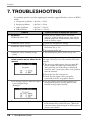
1
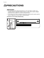
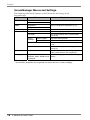
User’s Manual
Monochrome LCD Monitor
It shall be assured that the final system is in compliance to
IEC60601-1-1 requirements.
English
SAFETY SYMBOLS
This manual uses the safety symbols below. They denote critical information. Please read them
carefully.
WARNING
Failure to abide by the information in a WARNING may result in serious injury and
can be life threatening.
CAUTION
Failure to abide by the information in a CAUTION may result in moderate injury
and/or property or product damage.
Indicates a prohibited action.
Indicates to ground for safety.
• Power supplied equipment can emit electromagnetic waves, that could influence, limit or
result in malfunction of the monitor. Install the equipment in a controlled environment, where
such effects are avoided.
• This is a monitor intended for use in a medical image system.
Copyright© 2005 EIZO NANAO CORPORATION All rights reserved. No part of this manual
may be reproduced, stored in a retrieval system, or transmitted, in any form or by any means,
electronic, mechanical, or otherwise, without the prior written permission of EIZO NANAO
CORPORATION.
EIZO NANAO CORPORATION is under no obligation to hold any submitted material or
information confidential unless prior arrangements are made pursuant to EIZO NANAO
CORPORATION's receipt of said information. Although every effort has been made to ensure
that this manual provides up-to-date information, please note that EIZO monitor specifications
are subject to change without notice.
Apple and Macintosh are registered trademarks of Apple Computer, Inc.
VGA is a registered trademark of International Business Machines Corporation.
DPMS is a trademark and VESA is a registered trademark of Video Electronics Standards
Association.
Windows is a registered trademark of Microsoft Corporation.
PowerManager, RadiCS and RadiNET Pro are trademarks of EIZO NANAO CORPORATION.
ScreenManager, RadiForce and EIZO are registered trademarks of EIZO NANAO
CORPORATION in Japan and other countries.
2
English
TABLE OF CONTENTS
PRECAUTIONS ................................................................................ 4
1. INTRODUCTION ..................................................................................... 9
1-1. Features ........................................................................................................9
1-2. Package Contents..........................................................................................9
1-3. Controls & Connectors ..............................................................................10
2. CABLE CONNECTIONS....................................................................... 12
2-1. Before Connecting ......................................................................................12
2-2. Cable Connection .......................................................................................12
3. MENUS & FUNCTIONS ........................................................................ 15
3-1. ScreenManager ...........................................................................................15
3-2. CAL Switch Function..................................................................................17
3-3. Other Useful Functions ...............................................................................18
4. ADJUSTMENTS & SETTINGS ............................................................. 21
4-1. Brightness Adjustment ................................................................................21
4-2. Image Adjustments .....................................................................................21
4-3. Power-save Setup ........................................................................................21
5. MAKING USE OF USB (Universal Serial Bus) ................................... 23
6. ATTACHING AN ARM ........................................................................... 25
7. TROUBLESHOOTING........................................................................... 26
8. CLEANING ............................................................................................ 29
9. SPECIFICATIONS ................................................................................. 30
10. GLOSSARY......................................................................................... 33
TABLE OF CONTENTS
3
English
PRECAUTIONS
IMPORTANT!
• This product has been adjusted specifically for use in the region to which it was
originally shipped. If operated outside the region to which it was originally shipped,
the product may not perform as stated in the specifications.
• To ensure personal safety and proper maintenance, please read this section and the
caution statements on the unit (refer to the figure below).
[Location of the Caution Statements]
English
WARNING
If the unit begins to emit smoke, smells like something is burning, or
makes strange noises, disconnect all power connections immediately
and contact your dealer for advice.
Attempting to use a malfunctioning unit may result in fire, electric shock, or
equipment damage.
Do not open the cabinet or modify the unit.
Opening the cabinet or modifying the unit may result in fire, electric shock, or
burn.
Refer all servicing to qualified service personnel.
Do not attempt to service this product yourself as opening or removing covers
may result in fire, electric shock, or equipment damage.
Keep small objects or liquids away from the unit.
Small objects accidentally falling through the ventilation slots into the cabinet
or spillage into the cabinet may result in fire, electric shock, or equipment
damage.
If an object or liquid falls/spills into the cabinet, unplug the unit immediately.
Have the unit checked by a qualified service engineer before using it again.
Place the unit at the strong and stable place.
A unit placed on an inadequate surface may fall and result in injury or
equipment damage.
If the unit falls, disconnect the power immediately and ask your dealer for
advice. Do not continue using a damaged unit. Using a damaged unit may
result in fire or electric shock.
OK
Set the unit in an appropriate location.
Not doing so may result in fire, electric shock, or equipment damage.
* Do not place outdoors.
* Do not place in the transportation system (ship, aircraft, trains, automobiles,
etc.)
* Do not place in a dusty or humid environment.
* Do not place in a location where the steam comes directly on the screen.
* Do not place near heat generating devices or a humidifier.
* Do not place in an inflammable gas environment.
To avoid danger of suffocation, keep the plastic packing bags away
from babies and children.
Use the enclosed power cord and connect to the standard power outlet
of your country.
Be sure to remain within the rated voltage of the power cord.
Not doing so may result in fire or electric shock.
PRECAUTIONS
5
English
WARNING
To disconnect the power cord, grasp the plug firmly and pull.
Tugging on the cord may damage and result in fire or electric shock.
English
WARNING
Do not touch a damaged LCD panel directly with bare hands.
The liquid crystal which leaks from the panel is poisonous if it enters the eyes
or mouth.
If any part of the skin or body comes in direct contact with the panel, please
wash thoroughly. If some physical symptoms result, please consult your
doctor.
Follow local regulation or laws for safe disposal.
The backlight of the LCD panel contains mercury.
CAUTION
Handle with care when carrying the unit.
Disconnect the power cord and cables when moving the unit. Moving the unit
with the cord attached is dangerous. It may result in injury.
When handling the unit, grip the bottom of the unit firmly with both
hands ensuring the panel faces outward before lifting.
Dropping the unit may result in injury or equipment damage.
Do not block the ventilation slots on the cabinet.
* Do not place any objects on the ventilation slots.
* Do not install the unit in a closed space.
* Do not use the unit laid down or upside down.
Blocking the ventilation slots prevents proper airflow and may result in fire,
electric shock, or equipment damage.
Do not touch the plug with wet hands.
Doing so may result in electrical shock.
English
LCD Panel
The screen may have defective pixels. These pixels may appear as slightly light
or dark area on the screen. This is due to the characteristics of the panel itself,
and not the product.
The backlight of the LCD panel has a fixed life span. When the screen becomes
dark or begins to flicker, please contact your dealer.
Do not press on the panel or edge of the frame strongly, as this may result in
damage to the screen. There will be prints left on the screen if the pressed
image is dark or black. If pressure is repeatedly applied to the screen, it may
deteriorate or damage your LCD panel. Leave the screen white to decrease the
prints.
Do not scratch or press on the panel with any sharp objects, such as a pencil or
pen as this may result in damage to the panel. Do not attempt to brush with
tissues as this may scratch the LCD panel.
When the screen image is changed after displaying the same image for
extended periods of time, an afterimage may appear. Use the screen saver or
timer to avoid displaying the same image for extended periods of time.
When the monitor is cold and brought into a room or the room temperature
goes up quickly, dew condensation may occur inside and outside the monitor.
In that case, do not turn the monitor on and wait until dew condensation
disappears, otherwise it may cause some damages to it.
8
PRECAUTIONS
English
1. INTRODUCTION
Thank you for choosing an EIZO Monochrome Monitor.
1-1. Features
• DVI Digital input compliant (see p.33 ; for TMDS, see p.33)
• [Horizontal scanning frequency]
[Vertical scanning frequency]
[Resolution]
[Frame synchronous mode]
31 - 100 kHz
48 ~ 71.5 Hz (VGA text: 69 - 71 Hz)
3M pixels (Portrait: 1536 × 2048 dots (H × V))
59 - 61 Hz supported
• Cal Switch function for selecting an optimal calibration mode (see p.17)
• Selectable screen compliant with DICOM Part 14 (see p.33)
• Built-in Swing Sensor *1
• USB (Universal Serial Bus) hub support (see p. 23)
• Utility software “ScreenManager Pro for Medical”, which enables control of the
monitor from a Windows PC with a mouse or keyboard (refer to the EIZO LCD
Utility Disk).
• Monitor stand adjustable for different heights
• Ultra slim bezel
• 12bit monochrome signal input support*2
*1
*2
This sensor is used when calibrating the monitor with the exclusive software RadiNET Pro
(see "Options" p. 31).
Before a 12bit monochrome signal can be input, your graphics board must configured. For
details, refer to the user's manual for the graphics board.
1-2. Package Contents
Please contact your local dealer for assistance if any of the listed items are missing or
damaged.
• LCD Monitor*1
• EIZO LCD Utility Disk
• Power Cord
• User’s Manual
• Signal Cable (FD-C39)
• LIMITED WARRANTY
• EIZO USB Cable (MD-C93)
• Cleaning Kit “ScreenCleaner”
*1
The landscape position is the default monitor orientation. For the portrait position, rotate the
monitor ninety degrees counter-clockwise before installing it.
NOTE
• Please retain the packing materials for future transport of the monitor.
1. INTRODUCTION
9
English
1-3. Controls & Connectors
Front
English
Side / Rear
English
2. CABLE CONNECTIONS
2-1. Before Connecting
Before connecting your monitor to the PC, change the display screen settings resolution
(see p.33) and frequency in accordance with the charts below.
NOTE
• When your computer and display support VESA DDC, the appropriate resolution
and the refresh rate are set just by plugging your display into the computer without
any manual settings.
Resolution
720×400
Frequency
Dot Clock
VGA TEXT
70 Hz
165 MHz
(Max.)
Display mode
Portrait
Landscape
√
√
640×480
VGA
60 Hz
√
√
1536×1024
3M Packed Pixel
60 Hz
√
−
1024×1536
3M Packed Pixel
60 Hz
−
√
“√“: Supported
2-2. Cable Connection
NOTE
• Be sure that the power switches of both the PC and the monitor are OFF.
• Refer also to the PC user's manual when connecting the monitor.
• Before a 12bit monochrome signal can be input, your graphics board must be
configured. For details, refer to the user's manual for the graphics board.
1.
12
Rotate the monitor ninety degrees counter-clockwise into the portrait
position.
2. CABLE CONNECTIONS
English
2.
Connect the signal cable to the DVI-D input connector on the rear of
the monitor and to the video output connector on the PC.
After connecting, secure the cable connectors with the attached screw-in fasteners.
Signal cable
FD-C39
Power cord
Signal Cable
Signal cable (FD-C39)
Connector
PC
Video output connector / DVI
Exclusive graphics board
(See p.31)
3.
Connect the power cord to the power connector on the rear of the
monitor.
4.
Thread the power cord and signal cable through the cable holder on
the rear of the monitor stand.
NOTE
• When threading the cables through the cable holder, lead them to the cable
entrance side and pinch the projection to open the cable entrance.
• It is recommended that some slack be left in the cables to allow for smooth
adjustment of the monitor stand and easy rotation between the portrait and
landscape positions.
Projection
Cable holder
Cable entrance
2. CABLE CONNECTIONS
13
English
5.
Connect the other end of the power cord to a power outlet.
The monitor's power indicator will flash orange slowly.
WARNING
Use the enclosed power cord and connect to the standard
power outlet of your country.
Be sure to remain within the rated voltage of the power cord.
Not doing so may result in fire or electric shock.
The equipment must be connected to a grounded main
outlet.
Not doing so may result in fire or electric shock.
6.
Turn on the monitor's power by touching the power switch.
The monitor’s power indicator will light up green.
7.
Turn on the PC’s power.
If an image does not appear, refer to “7. TROUBLESHOOTING” (see p. 26) for
additional advice.
When finished, turn off the PC and the monitor.
NOTE
• Adjust the brightness of the screen depending on the brightness of your
environment.
• Be sure to take adequate rests. A 10-minute rest period each hour is
suggested.
8.
When inputting a 12bit monochrome signal, change the input signal
setting.
Change the settings in the ScreenManager <Signal Selection> menu. For more on
changing the settings, refer to "Signal Selection" (see p. 18).
9.
When using the software "ScreenManager Pro for Medical," connect
the monitor to a USB compliant Windows computer (or other USB
hub) with a USB cable.
Refer to “5. MAKING USE OF USB (Universal Serial Bus)” (see p. 23).
14
2. CABLE CONNECTIONS
English
3. MENUS & FUNCTIONS
3-1. ScreenManager
Screen adjustments and settings can be performed with the monitor controls.
ScreenManager
main menu
Directing Switches
Left, Down, Up, Right
CAL Switch menu
Enter Switch
NOTE
• The ScreenManager menu and CAL Switch menu cannot be displayed at the same
time.
How to use the ScreenManager
[Entering the ScreenManager]
(1) Touch the enter switch.
[Making adjustments and settings]
(1) Select the desired submenu icon with the directing switches and touch the enter
switch.
(2) Select the desired setting icon with the directing switches and touch the enter switch.
(3) Make any required adjustments with the directing switches.
[Exiting the ScreenManager]
(1) To return to the main menu, select the <Return> icon or touch the Down directing
switch twice, followed by the enter switch.
(2) To exit the ScreenManager, select the <Exit> icon or touch the Down directing
switch twice, followed by the enter switch.
NOTE
• Touching the enter switch twice also exits the ScreenManager.
3. MENUS & FUNCTIONS
15
English
ScreenManager Menus and Settings.
The following table briefly explains each of the menus and settings in the
ScreenManager.
Main menu
Setup
Sub menu
Signal Selection
Explanation
See 3-3. Other Useful Functions (p. 18)
Mode Preset
Mode
Brightness
See 4-1. Brightness Adjustment (p. 21)
Reset
PowerManager
DVI DMPM
See 4-3. Power-save Setup (p. 21)
Others
Border Intensity
See 4-2. Image Adjustments
Off Timer
Turn off the monitor after a specified time
(see p. 20).
Menu
Settings
*1
*2
16
Menu Position
Adjust the menu position
Menu Off Timer
Adjust how long to display the menu.
*1
Power Indicator
Disable the green power indicator (see
p.19).
Reset
Restore the factory default settings
(see p. 31).
Information
Information
View the ScreenManager settings, model
*2
name, serial number, and usage time .
Language
English, German, French,
Spanish, Italian, Swedish and
Japanese
Select the language of the ScreenManager
menus.
The display time of the CAL Switch menu can be adjusted.
Due to factory inspection, the usage time may not be “0 hours” at time of shipping.
3. MENUS & FUNCTIONS
English
3-2. CAL Switch Function
This function allows you to select the optimal display mode for your display images and
adjust the brightness in each mode.
CAL Switch Modes
Mode
1-DICOM
Description
Select this option to display images in the DICOM mode (see p.
33).
2-Native
Select this option to display images using the native
characteristics of the monitor panel.
3-CAL
Used for monitor calibration
* All modes can be calibrated independently.
The mode name can also be changed using the calibration kit (see Optional, p. 31).
How to use the CAL Switch Function
[Entering the CAL Switch menu]
(1) Touch the mode switch.
"CAL Switch" menu
"CAL Switch" mode
Brightness
[Selecting the CAL Switch mode]
(1) Touch the mode switch while the CAL Switch menu is displayed.
[Making brightness adjustments in CAL Switch mode]
(1) Select the desired setting icon with the Up and Down directing switches.
(2) Adjust the brightness value with the Left and Right directing switches.
[Closing the CAL Switch menu]
(1) Touch the enter switch.
NOTE
• The ScreenManager menu and CAL Switch menu cannot be displayed at the same
time.
• When switching between modes, the monitor can be set to display only the desired
modes, skipping any unnecessary modes (see p.19).
3. MENUS & FUNCTIONS
17
English
3-3. Other Useful Functions
Hardware Rotation
This function allows you to rotate the monitor image 90 degrees without using special
software or graphics board utilities.
[How to set]
(1) Shut down the computer if it is running. Also, turn off the monitor by touching the
power switch on the control panel.
(2) Turn off the monitor power.
(3) Touch the power switch while touching the mode switch on the conrtol panel. The
<Orientation> menu appears.
Orientation Menu
Mode Switch
Power Switch
æ ]
\ ƒ
j
˚
(4) Select the menu option according to your monitor orientation and touch the enter
switch.
Landscape
Portrait (SW)
Portrait (HW)
Monitor Orientation
Display Example
Select this option when using the
Landscape orientation.
A
Landscape
Portrait
Landscape
Portrait
Landscape
Portrait
Select this option when using the
Portrait orientation.
The software is used to rotate the
display image 90 degrees.
Select this option when using the
Portrait orientation.
The monitor function is used to rotate
the display image 90 degrees.
(5) Change the monitor orientation and restart the computer.
Signal Selection
This monitor supports the input of a 12bit monochrome signal.
[How to set]
(1) Select <Signal Selection> in the ScreenManager <Setup> menu.
(2) Select the type of signal to input.
18
A
Menu Option
3. MENUS & FUNCTIONS
English
Mode Preset
When CAL Switch mode is selected, the computer can be forced to display only specified
modes. Use this function when the display modes are restricted or when the display
should not be changed needlessly.
[How to set]
(1) Select <Mode Preset> in the ScreenManager <Setup> menu.
(2) Set each mode to “On” or “Off”.
NOTE
• You cannot disable all modes. Set one or more modes to “On”.
[How to cancel]
(1) Select <Mode Preset> in the ScreenManager <Setup> menu.
(2) Set the mode that you wish to display to “On”.
Power Indicator
Use the function to keep the power indicator without light while the monitor is
operational. (The power indicator is set by default to light when the power is turned
on.)
[Procedure]
(1) Select <Power Indicator> in the ScreenManager <Others> menu.
(2) Select “Disable”.
Adjustment Lock
Use this function to prevent any accidental changes to the monitor settings. The
following table shows which functions the adjustment lock affects.
Locked functions
• Display, adjustment, and setting of the ScreenManager
• Brightness adjustments to the CAL Switch mode
Unlocked function
• Selection of the CAL Switch mode with the mode switch
[How to lock]
(1) Turn off the monitor power by touching the power switch.
(2) Touch the power switch while touching the enter switch.
[How to unlock]
(1) Turn off the monitor power by touching the power switch.
(2) Touch the power switch while touching the enter switch, and then turn on the
monitor again. The adjustment lock is released, and the screen is displayed.
NOTE
• The adjustment lock function may activate when calibration is performed with the
calibration kit (see Optional, p. 31). The monitor can be unlocked using the same
unlocking procedure described above.
3. MENUS & FUNCTIONS
19
English
Off Timer
The off timer function causes the monitor to turn off automatically after a
predetermined amount of time has lapsed. This function was created to reduce the
afterimages particular to LCD monitors, which appear when the screen is left on for
long periods without use.
[How to set]
(1) Select <Off Timer> in the ScreenManager <Others> menu.
(2) Select “Enable” and touch the Right and Left directing switches to adjust the “On
Period” (1 to 23 hours).
[Off timer system]
PC
*1
Monitor
Power Indicator
On Period (1H - 23H)
Operational
Green
Last 15 min. in “On period”
Advance Notice *1
Flashing green
“On period” expired
Power off
Flashing orange slowly
By touching the power switch on the control panel during the Advance Notice period, the On
Period can be reset to 90 minutes. Resetting can be performed an unlimited number of times.
[How to restore power]
(1) Touch the power switch to return to a normal screen.
NOTE
• The off timer function works while the PowerManager is active, but there is no
advance notice before the monitor's power is turned off.
20
3. MENUS & FUNCTIONS
English
4. ADJUSTMENTS & SETTINGS
4-1. Brightness Adjustment
The brightness of the entire screen can be set to a desired level.
[Procedure]
(1) Select <Brightness> in the ScreenManager <Mode> menu.
(2) Make adjustments with the Left and Right directing switches.
The Left directing switch makes the screen darker, and the Right directing switch
makes it brighter.
NOTE
• Selecting <Reset> in the <Mode> menu resets the brightness of the selected CAL
Switch mode to the factory default setting.
4-2. Image Adjustments
When a low-resolution image is displayed, the brightness of the border area surrounding
the image (i.e., the dark area where no image appears) can be adjusted.
Border
[Procedure]
(1) Select <Border> in the ScreenManager <Others> menu.
(2) Make adjustments with the Left and Right directing switches. The Left directing
switch makes the border darker, and the Right directing switch makes it brighter.
4-3. Power-save Setup
Use the <PowerManager> menu in the ScreenManager to configure the power-save
setup. This monitor complies with the “DVI DMPM” (see p. 33).
NOTE
• Do your part to conserve energy, turn off the monitor when you are finished using it.
Disconnecting the monitor from the power supply is recommended to save energy
completely.
• Even if the monitor is in power-saving mode, USB compliant devices draw power
when they are connected to the monitor's USB ports (both upstream and
downstream). Therefore, the monitor's power consumption will change according to
which devices are connected, even if the monitor is in power-saving mode.
4. ADJUSTMENTS & SETTINGS
21
English
[Procedure]
(1) Set the PC's power saving settings.
(2) Select “DVI DMPM” in the <PowerManager> menu.
[Power saving system]
PC
Monitor
Power Indicator
On
Operation
Green
Power saving / Off mode
Power saving
Orange
[Power Resumption Procedure]
• Click the mouse or press a key on the keyboard to return to a normal screen.
22
4. ADJUSTMENTS & SETTINGS
English
5. MAKING USE OF USB
(Universal Serial Bus)
This monitor provides a hub which supports the USB standard. When connecting to a
USB compliant PC or another hub, the monitor functions as a hub to which the USB
compliant peripherals can be easily connected.
Required system environment
• PC equipped with USB ports or another USB hub connected to the USB compliant PC
• Windows 98/2000/Me/XP // Mac OS 8.5.1 or later
• USB Cable (MD-C93)
NOTE
• The USB hub function may not work properly depending on the PC, OS or
peripherals. Please consult the manufacturer of each device about the USB
support.
• When the monitor is not on, the peripherals connected to the downstream ports will
not operate.
• Even if the monitor is in a power saving mode, the devices connected to the
monitor's USB ports (both the upstream and the downstream) will function.
• The followings are procedures for the Windows 98/Me/2000/XP and Mac OS.
Connecting to the USB HUB
1.
Connect the monitor to the PC with the signal cable (see p.12) first,
then turn on the PC.
2.
Connect the upstream port of the monitor to the downstream port of
the USB compliant PC or another hub by using the USB cable.
After connecting the USB cable, the USB function can be set up automatically.
Upstream Ports
Upstream port:
Connect the USB compliant PC
or another hub using the USB
cable.
To Downstream Ports of
the PC or Another Hub
5. MAKING USE OF USB (Universal Serial Bus)
23
English
3.
After setting up, the monitor's USB hub is available for connecting
USB compliant peripherals to the downstream ports of the monitor.
Connecting Examples
Monitor
Mouse
PC
Keyboard
Downstream ports:
Connect the cables from USB
compliant peripherals such as a
mouse, keyboard, etc.
Downstream Port
ScreenManager Pro for Medical (for Windows)
For further details about the “ScreenManager Pro for Medical (for Windows)”, refer to
the EIZO LCD Utility Disk.
24
5. MAKING USE OF USB (Universal Serial Bus)
English
6. ATTACHING AN ARM
The LCD monitor can be used with an arm by removing the tilt stand and attaching the
arm or stand to the LCD monitor.
NOTE
• If you will use the arm or stand of other manufacturers, confirm the followings to the
manufacturers before selecting.
- Hole spacing on the arm mounting: 100 mm x 100 mm (VESA compliant)
- Supportable Weight: Total weight of the monitor (without stand) and attaching
equipment such as a cable
- TÜV/GS approved arm or stand
• Please connect cables after attaching an arm stand.
Setup Procedure
1.
Hold the center of the stand mounting cover and slide them
rightward or leftward to remove the mounting cover.
2.
Lay the LCD monitor down. Do not scratch the panel.
3.
Remove the tilt stand by loosening the screws.
(4 pcs of M4 x 10 BZn/Fe)
4.
Attach an arm stand to the LCD monitor securely.
English
7. TROUBLESHOOTING
If a problem persists even after applying the remedies suggested below, contact an EIZO
dealer.
• No picture problems → See No.1 ~ No.2
• Imaging problems
→ See No.3 ~ No.6
• Other problems
→ See No.7 ~ No.10
• USB problems
→ See No.11 ~ No.12
Problem
• Indicator status: Off
Check that the power cord is connected
correctly. If the problem persists, turn off the
monitor power for a few minutes, then turn it
back on and try again.
• Indicator status: Green
Check the <Brightness> setting.
• Indicator status: Orange
Try pressing a key on the keyboard or clicking
the mouse (see p. 21).
Try turning the PC on.
• Indicator status: Flashing orange
slowly
Try touching the power switch (see p. 20).
1. No picture
2.
One of the error messages shown
below remains on the screen for 40
second.
• The message appears when the signal
is out of input range.
(Example)
3. The screen is too bright or too dark.
26
Points to check and possible solutions
7. TROUBLESHOOTING
These messages appear when the video signal is
not input correctly, even if the monitor functions
properly.
The massage might appear because some PCs
do not output the video signal immediately
after powering on. If the image is displayed
correctly after a short time, there is no problem
with the monitor.
Check that the PC is turned on.
Check that the signal cable is properly
connected to the PC or graphics board.
Use the graphics board’s utility software to
change the frequency setting. (Refer to the
manual of the graphics board.)
Adjust the <Brightness> (The backlight of the
LCD monitor has a fixed life span. When the
screen becomes dark or begins to flicker, please
contact your dealer.)
English
Problem
Points to check and possible solutions
4.
Afterimages appear.
Do you use the screen saver or timer (p.20)
when displaying the same image for extended
periods of time?
Afterimages are particular to LCD monitors.
Avoid displaying the same image for extended
periods of time.
5.
The screen has defective pixels
(e.g. appears slightly light or dark).
This is due to the characteristics of the panel
itself and not the LCD product.
6. Fingerprints remain on the screen.
Leaving the screen white may solve the
problem
7. The ScreenManager main menu
does not operate.
The adjustment lock is probably on. To unlock
it, first turn off the monitor. Touch the power
switch while touching the enter switch, and
then turn on the monitor again (see p. 19).
Make sure the control panel switches are not
wet or soiled. Lightly wipe the surface of the
control panel, and try touching the switches
again with dry hands.
Make sure not to wear gloves. Remove any
gloves, and try touching the switches again
with dry hands.
8.
Make sure the control panel switches are not
wet or soiled. Lightly wipe the surface of the
control panel, and try touching the switches
again with dry hands.
Make sure not to wear gloves. Remove any
gloves, and try touching the switches again
with dry hands.
The control panel does not operate.
CAL Switch mode does not operate.
9. The monitor turns off while in use.
Make sure the air vents are not blocked.
Make sure high-temperature equipment is not
located nearby.
10. The signal frequency does not
change after installing the “Monitor
information file” from the supplied
utility disk on a Windows
98/2000/Me/XP PC.
Use the graphics board’s utility software to
change the input signal frequency.
11. The USB function does not operate.
Check that the USB cable is correctly
connected.
Check that the PC and OS are USB compliant.
(For verification of USB support, consult the
manufacturer of each system.)
Check the USB setting in the PC's BIOS. (For
details, refer to the PC user's manual.)
7. TROUBLESHOOTING
27
English
Problem
12. The PC freezes.
The peripherals connected to the
USB downstream ports do not
operate.
28
7. TROUBLESHOOTING
Points to check and possible solutions
Check that the USB cable is connected
correctly.
Try connecting the peripheral to another USB
downstream port. If the problem is solved by
doing this, contact an EIZO dealer. (For
details, refer to the manual of the PC.)
Try executing the following method.
- Restarting the PC
- Connecting the PC and peripherals directly
If the problem is solved by doing this, contact
an EIZO dealer.
The power switch on an Apple keyboard will
not operate when connected to a USB
downstream port on the monitor. Connect the
keyboard directly to the Apple PC. (For details,
refer to the Apple PC user's manual.)
English
8. CLEANING
Periodic cleaning is recommended to keep the monitor looking new and to prolong its
operation lifetime.
NOTE
• Never use thinner, benzene, alcohol (ethanol, methanol, or isopropyl alcohol),
abrasive cleaners, or other strong solvents, as these may cause damage to the
cabinet or LCD panel.
• Make sure to turn off the monitor before cleaning it.
Cabinet
To remove stains, wipe the cabinet with a soft, lightly moistened cloth using a mild
detergent. Do not spray wax or cleaner directly into the cabinet. (For details, refer to
the PC user's manual.)
Panel Protector
• The LCD surface can be cleaned with a soft cloth, such as cotton or lens paper.
• For stubborn stains, use the enclosed cleaning kit “ScreenCleaner”, or gently wipe the
affected area using a cloth moistened with water or an ethanol-based cleaner.
8. CLEANING
29
English
9. SPECIFICATIONS
LCD Panel
52.9 cm (20.8 inch), TFT Monochrome LCD panel
Anti-Glare Hard Coating 3H, Response Time : 50ms
Viewing Angle
Horizontal: 170°, Vertical: 170° (CR≥10)
Panel Protector
Surface treatment: Anti-reflective coating (both sides)
Surface hardness: 6H pencil hardness or higher
Visible reflectance: 1.0% or less
Visible light transmittance: 96% or more
Dot Pitch
0.207 mm
Horizontal Scan Frequency
31 ~ 100 kHz
Vertical Scan Frequency
48 ~ 71.5 Hz (VGA TEXT: 69 ~ 71 Hz)
Resolution
3M pixels (Portrait: 1536 × 2048 dots (H × V))
Dot Clock (Max.)
165 MHz
Gray Scale
4096 steps of 8161 steps (12bit monochrome signal input)
Brightness (Recommended)
450 cd/m2 (approx.70%)
Display Area
423.9 mm (H) × 318.0 mm (V) (17. 0” (H) × 12.8” (V))
Power Supply
100-120/200-240 VAC±10%, 50/60 Hz, 1.0-0.8A /0.5-0.4 A
Power Consumption
Min. : 90 W
Max.: 100 W (With USB)
Power Saving Mode: Less than 3 W (for single signal input
without USB)
Main power off : 0 W
Input Connector
DVI-D x 1
Input Signal
TMDS (Single Link)
Plug & Play
VESA DDC 2B / EDID structure 1.3
Dimensions
With stand
368.0 mm (W) x 515.5∼ 597.5 mm (H) x 209.0 mm (D)
(14.5”(W) x 20.3” ∼ 23.5” (H) x 8.2”(D))
without stand
368 mm (W) x 486 mm (H) x 94mm (D)
(14.5”(W) x 19.1”(H) x 3.5”(D))
Weight
With stand
10.0 kg (22 lbs.)
without stand
7.0 kg (15.4 lbs.)
Environment
Conditions
Temperature
Operating: 0 °C ∼ 35 °C (32 °F ∼ 95 °F)
Storage: - 20 °C ∼ 60 °C (- 4 °F ∼ 140 °F)
Humidity
30 % to 80 % R.H. Non-condensing
Pressure
Operating: 700 to 1,060 hPa
Storage: 200 to 1,060 hPa
Standard
USB Specification Revision 2.0
USB ports
Upstream port × 1, Downstream port × 2
Communication
Speed
480 Mbps (high), 12 Mbps (full), 1.5 Mbps (low)
Power Supply
Downstream: 500 mA for each (Max.)
USB
30
Certifications and Standards
TÜV Rheinland /GM, CB, NRTL/C-TÜV, CE (93/42/EEC),
FCC-B
Classification of Equipment
Type of protection against electric shock: Class I
EMC class: EN60601-1-2: 2001 Group 1 Class B
Classification of medical device (MDD 93/42/EEC): Class I
9. SPECIFICATIONS
English
Dimensions
mm (inches)
368 (14.5)
320 (12.6)
TILT:
40
597.5 (23.5)
82 (3.2)
94 (3.7)
68 (2.7)
301.5 (11.9)
272.5 (10.7)
29.5 (1.2)
90
426 (16.8)
486 (19.1)
168 (6.6)
35
35
SWIVEL
15.5(0.6)
Front
209 (8.2)
Side
Top
Default Settings
Signal Selection
8bit/10bit
Orientation
Portrait (SW)
CAL Switch Mode
1-DICOM
Brightness
Fixed at the factory
PowerManager
DVI DMPM
Off Timer
Menu Settings
Disable
Menu Size
Menu Off Timer
Language
Normal
45 seconds
English
Optional
Arm, Stand
EIZO “LA-131-D”
EIZO “LA-030-W”
EIZO “LA-011-W”
: LCD Monitor Flexible Arm
: Wall Mount Arm for LCD Monitor
Graphics board
8bit, 10bit, and 12bit monochrome signals supported
• RealVision “VREngine/SMD-3PCI”
8bit and 10bit monochrome signals supported
• Matrox “MED3mp-PPP”
8bit monochrome signals supported
• RealVision “VREngine/MD3W”
Calibration Kit
EIZO “RadiCS GX2” Ver.2.00 or later
Network QC
Management Software
EIZO “RadiNET Pro” Ver.2.00 or later
9. SPECIFICATIONS
31
English
Pin Assignment
DVI-D Connector
1 2 3 4 5 6 7 8
9 10 11 12 13 14 15 16
17 18 19 20 21 22 23 24
Pin No.
Signal
Pin No.
Signal
Pin No.
Signal
1
TMDS Data2-
9
TMDS Data1-
17
TMDS Data0-
2
TMDS Data2+
10
TMDS Data1+
18
TMDS Data0+
3
TMDS Data2/4 Shield
11
TMDS Data1/3 Shield
19
TMDS Data0/5 Shield
4
NC*
12
NC*
20
NC*
5
NC*
13
NC*
21
NC*
6
DDC Clock (SCL)
14
+5V Power
22
TMDS Clock shield
English
10. GLOSSARY
DICOM
(Digital Imaging and Communication in Medicine)
The DICOM standard was developed by the American College of Radiology and the
National Electrical Manufacturer's Association of the USA.
A DICOM-compatible device connection enables the transfer of medical images and
information. Part 14 of DICOM defines the standards for digital, grayscale medical
image display.
DVI
(Digital Visual Interface)
A digital flat panel interface. DVI can transmit digital data without loss and directly
from the PC using the signal transition method “TMDS” (see p. 33).
There are two kinds of DVI connectors: the DVI-D connector for digital signal input
only, and the DVI-I connector for both digital and analog signal inputs.
DVI DMPM
(DVI Digital Monitor Power Management)
The Power management system for the digital interface. The “Monitor ON” status
(operation mode) and the “Active Off” status (power-saving mode) are indispensable
for the DVI-DMPM as the monitor's power mode.
Resolution
The LCD panel consists of a fixed number of pixel elements which are illuminated to
form the screen image. The EIZO G33 display panel consists of 1536 horizontal
pixels and 2048 vertical pixels. At a resolution of 1536 x 2048, all pixels are
displayed as a full screen.
As a standard default space, sRGB allows Internet users to closely match colors.
TMDS
(Transition Minimized Differential Signaling)
A signal transition method for the digital interface.
10. GLOSSARY
33
For U.S.A, Canada, etc. (rated 100-120 Vac) Only
FCC Declaration of Conformity
We, the Responsible Party
EIZO NANAO TECHNOLOGIES INC.
5710 Warland Drive, Cypress, CA 90630
Phone: (562) 431-5011
declare that the product
Trade name: EIZO
Model: RadiForce G33
is in conformity with Part 15 of the FCC Rules. Operation of this product is subject to the
following two conditions: (1) this device may not cause harmful interference, and (2) this
device must accept any interference received, including interference that may cause undesired
operation.
This equipment has been tested and found to comply with the limits for a Class B digital
device, pursuant to Part 15 of the FCC Rules. These limits are designed to provide
reasonable protection against harmful interference in a residential installation. This
equipment generates, uses, and can radiate radio frequency energy and, if not installed and
used in accordance with the instructions, may cause harmful interference to radio
communications. However, there is no guarantee that interference will not occur in a
particular installation. If this equipment does cause harmful interference to radio or
television reception, which can be determined by turning the equipment off and on, the user
is encouraged to try to correct the interference by one or more of the following measures.
* Reorient or relocate the receiving antenna.
* Increase the separation between the equipment and receiver.
* Connect the equipment into an outlet on a circuit different from that to which the receiver
is connected.
* Consult the dealer or an experienced radio/TV technician for help.
Changes or modifications not expressly approved by the party responsible for compliance
could void the user’s authority to operate the equipment.
Note
Use the attached specified cable below or EIZO signal cable with this monitor so as to keep
interference within the limits of a Class B digital device.
- AC Cord
- Shielded Signal Cable (enclosed)
Canadian Notice
This Class B digital apparatus complies with Canadian ICES-003.
Cet appareil numérique de le classe B est comforme à la norme NMB-003 du Canada.
Recycle Auskunft
Die Rücknahme dieses Produktes nach Nutzungsende übernimmt EIZO in Deutschland
zusammen mit dem Partner MIREC GmbH & Co. KG. Dort werden die Geräte in ihre
Bestandteile zerlegt, die dann der Wiederverwertung zugeführt werden. Um einen Abholtermin
zu vereinbaren und die aktuellen Kosten zu erfahren, benutzen Sie bitte folgende Rufnummer:
02153-73 35 00. Weitere Informationen finden Sie auch unter der Internet-Adresse:
www.eizo.de.
Recycling Information for customers in Switzerland:
All recycling information is placed in the SWICO’s website.
http://www.swico.ch
Recycling-Information für Kunden in der Schweiz:
Alle Informationen zum Thema Recycling finden Sie auf der Homepage des Brancheverbandes
SWICO.
http://www.swico.ch
Renseignements de recyclage pour les clients en Suisse:
Vous trouvez tous les renseignements pour le sujet de recyclage sur la page WEB de I’UNION
DE BRAN CHE SWICO.
http://www.swico.ch
Recycling Information for customers in USA:
All recycling information is placed in the EIZO Nanao Technologies, Inc’s website.
http://www.eizo.com/contact/index.html
Återvinnings information för kunder i Sverige:
All information om återvinning finns på Eizo Europe AB:s hemsida:
www.eizo.se