1
301 & 601
Mic/Line Mixers
Operation Manual
Biamp Systems | 9300 S.W. Gemini Drive | Beaverton, OR | 97008 | USA | +1.503.641.7287 | www.biamp.com
301 & 601
TABLE OF CONTENTS
Introduction
pg. 1
Front Panel
pg. 2
Rear Panel
pg. 3
Remote Control
pg. 4
Specifications & Block Diagram
pg. 5
Warranty
pg. 6
blank
August, 2009
301 & 601
INTRODUCTION
The 301 & 601 are single rack space, three input & six input mic/line mixers. Each input channel uses a differentially balanced, discrete
transistor mic/line preamplifier for low noise and low distortion performance. Inputs are provided to accept signals from microphones
and/or line level devices. Special features, including limiters and remote level control, make the 301 & 601 extremely versatile. The 301 &
601 mixers are dependable, easy to install, simple to operate, and are covered by Biamp Systems’ five-year warranty.
301 & 601 features include:
♦ three electronic balanced mic/line input channels (301)
♦ six electronic balanced mic/line input channels (601)
♦ 30dB rear panel Pad switch on each input channel
♦ 40dB screwdriver-adjust Trim on each input channel
♦ +10dB Peak LED indicator on each input channel
♦ rotary level control on each input channel
♦ auto-muting of one channel for "talk-over" applications
♦ +24 volt Phantom Power assign switch on each input
♦ electronic balanced main output with rotary level control
♦ remote control of main level from up to 2000 feet away
♦ main patch insert point for external processing devices
♦ main stacking input accepts signals from other mixers
♦ screwdriver-adjust tone controls & limiter on main output
♦ -20dB Signal Present LED indicator for main output
♦ all input/output/control on plug-in barrier strip connectors
♦ covered by Biamp Systems’ five-year warranty
♦
marked and UL / C-UL listed power source
1
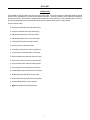
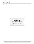
FRONT PANEL
Trim: These screwdriver adjustable controls provide 40dB of gain adjustment to compensate for different input signal levels. For best
performance, adjust Trim so the +10 Indicator flashes only on occasional peaks in signal level (see +10 Indicator below).
+10 Indicator (Peak): These red LEDs indicate signal level in the channel has reached +10dB (8dB below clipping). For best
performance, adjust Trim so the Peak Indicator flashes only on occasional peaks in signal level (see Pad on next page).
Channel Level: These controls adjust the level of channel signal sent to the Main Out section. Level control settings will vary from
channel to channel, depending upon the desired mix. However, for best performance, higher settings should center around the 12 o'clock
position (unity gain). One of the channels includes a level "ducking" feature, which can be triggered when signal is present in selected
other channels (see Ch 3/6 Duck on next page). This "ducking" feature is useful in page-over-music applications.
Bass: This screwdriver-adjustable control sets the low-frequency equalization (Bass) for the Main Out section. Bass is a shelving type
filter, which provides +/-10dB of gain adjustment for frequencies below 100Hz.
Treble: This screwdriver-adjustable control sets the high-frequency equalization (Treble) for the Main Out section. Treble is a shelving
type filter, which provides +/-10dB of gain adjustment for frequencies above 10kHz.
Master Level: This control adjusts the overall level of signal sent to Main Out (see Rear Panel: Main Out on next page). The Master
Level control is used to make adjustments in volume level. However, for best performance, higher settings should center around the 12
o'clock position (unity gain). Sound system amplifiers may then be set for the appropriate volume level. Main Out level can also be
adjusted via remote control (see Remote on next page).
-20 Indicator (Signal Present): This red LED indicates signal level at the Main Out is above -20dB (normal signal level). Once the
Master Level control has been adjusted, this indicator will remain lit whenever signal is present at Main Out.
Threshold: A limiter is provided at the Main Out section to help eliminate unwanted peaks in program signal level. This screwdriver
adjustable control sets the threshold level, at which the limiter is activated. For most applications, set this control so the Limit Indicator
flashes only on occasional peaks in signal level (see Limit Indicator below). Counter-clockwise adjustment lowers the threshold, increasing
the amount of limiting. Clockwise adjustment raises the threshold, ultimately removing the limiter from operation. This control is factory set
fully clockwise (limiter off).
Limit Indicator: This red LED indicates when the limiter is activated by program signal levels that exceed the threshold setting.
On Indicator: When the power transformer is plugged in, and AC power is applied to the mixer, the red On indicator remains lit.
2
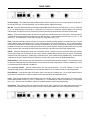
REAR PANEL
DC Power Supply: The included power supply module provides 24 Volt DC power to the mixer. It is connected to the DC Power Jack on
the rear side of the mixer. To ensure compatibility, only use a Biamp Systems’ supplied power supply.
Main Out: These three terminals provide the electronically balanced Main Out from the mixer, wired with high to (+), low to (-), and ground
to (d). For unbalanced output, connect high to (+) and ground to (d), leaving low (-) unconnected. Main Out signal is a mix of the input
channel signals, plus signal from Stack In, as well as any processing which may be inserted at Patch (see Stack In & Patch below).
Stack In: These three terminals provide a line level input for signals from external devices, such as other mixers. Stack Input signal is
combined with the channel signals, before being sent to the Main Out section. Connect balanced inputs with high to (+), low to (-), and
ground to (d). For unbalanced use, connect inputs with high to (+) and ground to both (-) & (d).
Patch: These three terminals provide an insert point for connection of external processing equipment at the Main Out section. Patch is
post-EQ (Bass & Treble) and pre-Master Level. The (out) terminal provides a send to the external device. The (in) terminal provides a
return from the external device Ground for both connections is supplied by the (d) terminal. Patch may also be used as an unbalanced,
pre-Master Level output, with the (out) terminal as the send and the (d) terminal as ground. Depress the Patch Enable switch only when
Patch is used as an insert, and release the Patch Enable switch when Patch is used as an output (see Enable Switches below).
Remote: These three terminals allow remote control of the Main Out level. Remote controls can be level pots and/or mute switches.
Controls may be wired up to 2000 feet from the mixer, using 2-conductor shielded cable (see Remote Control on page 4). Potentiometers
should be 5k~50k ohms (linear taper). Switches may be used alone (on/off) or with variable resistors (adjustable mute). An external ramp
voltage may also be used. Depress the Remote Enable switch only when using remote controls (see Enable Switches below).
Enable Switches: These switches activate the normal functions of the Patch & Remote terminals (see above). Patch terminals may still
be used as an unbalanced output even when disabled. Remote terminals do nothing unless enabled. If Remote is enabled, but no control
is connected, signal will be muted (off) at the Main Out.
Ch 3 / Ch 6 Duck switches: These DIP switches assign which input signals (Channels 1 & 2 on 301; Channels 1~5 on 601) will
automatically trigger ducking (-15dB attenuation) on the last channel (Channel 3 on 301; Channel 6 on 601) for talk-over applications.
Phntm Switches: These switches assign +24V Phantom Power to the Inputs (for condenser mics). Do not assign Phantom Power for
inputs other than condenser mics. Always turn Channel Level controls down before switching Phantom Power.
Inputs: These terminals provide electronically balanced input to the channels, and will accept either microphone or line-level signals.
Connect balanced inputs with high to (+), low to (-), and ground to (d). For unbalanced use, connect inputs with high to (+) and ground to
both (-) & (d). Phantom Power is available for operation of condenser microphones (see Phntm Switches above).
Pad Switches: These switches reduce the channel input signal level by 30dB. Depress this switch when channel input signal levels
exceed the normal operating range of the front panel Trim control. Pad is typically released for mic input and depressed for line input.
3
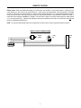
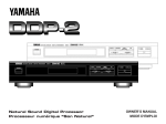
REMOTE CONTROL
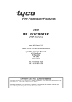
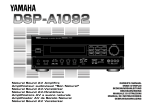
Remote Control: When using a slide potentiometer as a remote control, wire with High (T) to the voltage terminal (‘V’), Wiper (W) to the
control terminal ("C"), and Low (B) to the ground terminal (‘d’). When using a rotary potentiometer, wire with High (CW) to the voltage
terminal ("V"), Wiper (W) to the control terminal ("C"), and Low (CCW) to the ground terminal ("d"). Potentiometers should be linear taper,
of any value from 5k ohms to 50k ohms, and may be wired up to 2000 feet from the mixer. Cable should be 2-conductor with shield. A
remote level control wall-plate, model RP-L1, is available. If an on/off switch is utilized, "ON" position should connect the voltage terminal
(‘V") to the control terminal ("C"). Different wiring techniques, using both a potentiometer and a switch, can provide either level and mute
functions or adjustable muting attenuation.
NOTE: The rear panel Remote Enable switch must be depressed for remote controls to function (see Enable Switches on page 3).
REMOTE CONTROL WIRING DIAGRAM
off
on
toggle
switch
rotary
pot.
ccw
+10V C
w
T
cw
W
B
gnd
4
slide
pot.
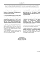
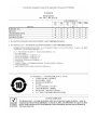
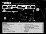
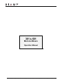
SPECIFICATIONS & BLOCK DIAGRAM
5
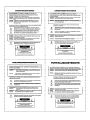
WARRANTY
BIAMP SYSTEMS IS PLEASED TO EXTEND THE FOLLOWING 5-YEAR LIMITED WARRANTY TO THE
ORIGINAL PURCHASER OF THE PROFESSIONAL SOUND EQUIPMENT DESCRIBED IN THIS MANUAL
1. BIAMP Systems warrants to the original purchaser of new
products that the product will be free from defects in material
and workmanship for a period of 5 YEARS from the date of
purchase from an authorized BIAMP Systems dealer, subject to
the terms and conditions set forth below.
2. If you notify BIAMP during the warranty period that a BIAMP
Systems product fails to comply with the warranty, BIAMP
Systems will repair or replace, at BIAMP Systems' option, the
nonconforming product. As a condition to receiving the benefits
of this warranty, you must provide BIAMP Systems with
documentation that establishes that you were the original
purchaser of the products. Such evidence may consist of your
sales receipt from an authorized BIAMP Systems dealer.
Transportation and insurance charges to and from the BIAMP
Systems factory for warranty service shall be your responsibility.
3. This warranty will be VOID if the serial number has been
removed or defaced; or if the product has been altered,
subjected to damage, abuse or rental usage, repaired by any
person not authorized by BIAMP Systems to make repairs; or
installed in any manner that does not comply with BIAMP
Systems' recommendations.
4. Electro-mechanical fans, electrolytic capacitors, and normal
wear and tear of items such as paint, knobs, handles, and
covers are not covered under this warranty.
5.
THIS WARRANTY IS IN LIEU OF ALL OTHER
WARRANTIES, EXPRESS OR IMPLIED. BIAMP SYSTEMS
DISCLAIMS ALL OTHER WARRANTIES, EXPRESS OR
IMPLIED, INCLUDING, BUT NOT LIMITED TO, IMPLIED
WARRANTIES OF MERCHANTABILITY AND FITNESS FOR A
PARTICULAR PURPOSE.
6. The remedies set forth herein shall be the purchaser's sole
and exclusive remedies with respect to any defective product.
7. No agent, employee, distributor or dealer of Biamp Systems
is authorized to modify this warranty or to make additional
warranties on behalf of Biamp Systems.
statements,
representations or warranties made by any dealer do not
constitute warranties by Biamp Systems. Biamp Systems shall
not be responsible or liable for any statement, representation or
warranty made by any dealer or other person.
8. No action for breach of this warranty may be commenced
more than one year after the expiration of this warranty.
9. BIAMP SYSTEMS SHALL NOT BE LIABLE FOR SPECIAL,
INDIRECT, INCIDENTAL, OR CONSEQUENTIAL DAMAGES,
INCLUDING LOST PROFITS OR LOSS OF USE ARISING
OUT OF THE PURCHASE, SALE, OR USE OF THE
PRODUCTS, EVEN IF BIAMP SYSTEMS WAS ADVISED OF
THE POSSIBILITY OF SUCH DAMAGES.
Biamp Systems
9300 S.W. Gemini Drive
Beaverton, Oregon 97008
(503) 641-7287
585.0162.90B
DoC MLM201003
EC Declaration of Conformity
Biamp Systems Corporation, as manufacturer having sole responsibility, hereby
declares that the following described product complies with the applicable provisions of
the DIRECTIVES below except as noted herein. Any alterations to the product not
agreed upon and directed by Biamp Systems Corporation will invalidate this declaration.
Product Models:
301, 601, 801i
Product Description:
Mic/Line Mixers
Applicable EC Directives:
Applicable Harmonized Standards:
LVD Directive (2006/95/EC)
Safety
EN 60065:2002
EMC Directive (2004/108/EC)
Emissions
Immunity
EN 55103-1:1996, Environment E2
EN 55103-2:1996
Special Considerations for Product Environment or Compliance:
Use only Biamp Systems supplied 24 VDC External Power Supply Adaptor.
Shielded cabling must be used for system connections.
Technical Construction File, Location and Contact:
Biamp Systems, Inc.
9300 S.W. Gemini Drive
Beaverton, OR USA 97008
phone:
fax:
e-mail:
Authorized Representative:
Larry Copley, Compliance Engineer
Authorized Signature:
Issued:
March, 2010 (503) 641.7287
(503) 626.0281
[email protected]