1
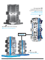
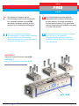
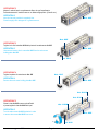
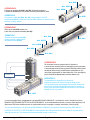
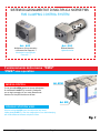
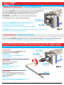
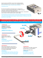
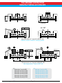
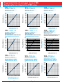
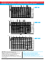
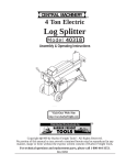
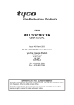
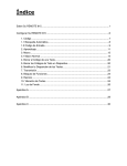
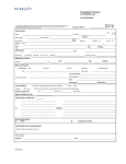
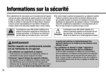
CONSIGLI SULL’ USO E MANUTENZIONE PER MORSE FMS “TRE MORSE IN UNA” ! Singola , doppia e autocentrante! INSTRUCTIONS FOR THE USE AND MAINTENANCE OF FMS VISES “THREE VISES IN ONE” ! Single, double , self-centering! GERARDI SPA 21015 LONATE POZZOLO (VA) Italy via Giovanni XXIII, 101 tel. +39.0331.303911 - fax +39.0331.30153 www.gerardispa.com - [email protected] Cubo morsa doppia FMS con ganasce oscillanti (su un lato) e ganasce a gradini (su un altro lato) FMS double vise tower with floating jaws (on front side) and steps jaws (on the other side) Morse FMS Art. 800 montate verticalmente FMS vises Art. 800 vertical application MONOBLOCCO SOLID PIECE Cubi morsa doppia FMS FMS double vise towers www.gerardi.it Pag. 2 - FMS vises Serie FMS Series 1° Fare riferimento al disegno esploso, che accompagna tutte le morse e che riporta tutti i particolari costituenti la morsa FMS, denominati con numero di articolo, e riferiti sempre al tipo di morsa all’atto dell’acquisto. 2° La morsa può essere smontata seguendo attentamente tutte le istruzioni ed operazioni qui sotto descritte. Si consiglia vivamente di marcare pezzi e posizioni di tutti i particolari e rimontarli esattamente nella medesima posizione in cui sono stati smontati. 1° Refer to your explosion view drawing accompanying all our vises and which identifies each part with its own article number. When requesting service or spare parts always refer to the vise type number. carefully following the procedure and instruc2° By tions the vise can be dismantled. We suggest all parts and their positions be marked so they can readily be reassembled to their original state. OPERAZIONE 1 Togliere tutte le ganasce dal modulo base Art.855 OPERATION 1 Remove all the jaws from the vise module Art.855 Art. 855 www.gerardi.it Pag. 3 - FMS vises OPERAZIONE 2 Adesso il modulo base è completamente libero da ogni impedimento. Pulire attentamente il modulo base con un diluente appropriato. (Gasolio ecc). OPERATION 2 Now the vise body module is completely free. Clean throughly with detergent oil or grease remover. Art. 855 Art. 825 OPERAZIONE 3 Togliere le 4 viti di testa Art. 801I dalla piastra di contenimento Art. 825 OPERATION 3 Art. 855 Unscrew and remove the 4 screws Art. 801I from the main screw holding plate Art. 825 Art. 801I OPERAZIONE 4 Togliere la piastra di contenimento Art. 825 Art. 825 OPERATION 4 Art. 855 Remove the main screw holding plate Art. 825 Art. 801G Art. 830 OPERAZIONE 5 Girare la vite Art. 822 in senso orario affinchè si possa togliere la vite Art. 801G dai ripari. Art. 829A OPERATION 5 Turn the main screw Art. 822 clockwise in order to remove the screws Art.801G from cover. Art. 855 Art. 822 www.gerardi.it Pag. 4 - FMS vises Art. 830 Art. 801S OPERAZIONE 6 Collegare le due slitte Art. 829A - Art. 830, utilizzando la piastrina in dotazione Art. 801S, per non perdere la fase di posizionamento slitte. Art. 829A OPERATION 6 Connect the 2 slides Art. 829A - Art. 830, using the plate in the STD equipment Art. 801S, in order not to lose the slides reference on the main screw and also for safety reasons. Art. 855 OPERAZIONE 7 Sfilare la vite (Art. 822) assieme con le due slitte e la piastra intermedia (Art. 823) OPERATION 7 Art. 830 Remove the main screw (Art.822) together with the 2 slides and the intermediate plate (Art.823) Art. 801 Art. 815S Art. 829A Art. 822 Art. 823 OPERAZIONE 8 Per rimontare la morsa, eseguire tutte le 8 operazioni in senso inverso senza forzare nel rimontaggio nessun particolare. L’unica manutenzione richiesta (a parte la periodica pulizia interna ed esterna della morsa) è la lubrificazione settimanale con olio molto fluido negli appositi fori situati nelle slitte. Il foro da scegliere per la lubrificazione dipende dalla posizione della morsa. Fori di lubrificazione Lubrification holes OPERATION 8 To reassemble the vise perform the 8 previous operations reverse order without forcing any stage or part. The only maintenance required (apart from periodic internal and external vise cleaning) is weekly lubrication with low viscosity oil in the proper holes in the slides.Which lubrication hole is chosen depends on the vise position. Art. 855 La morsa sopradescritta è completamente a chiusura MECCANICA MANUALE. I vari dispositivi, ossia i moltiplicatori di forza MANUALI,OLEODINAMICI,ELETTRICI ed OLEOPNEUMATICI, sono completamente autonomi e possono essere applicati o tolti dalle morse FMS senza modifica alcuna. La chiusura della morsa è comunque, e sempre, meccanica. (Vite/chiocciola) This vise described above is for fully manual MECHANICAL CLAMPING. The various accessories we offer, MECHANICAL, HYDRAULIC, ELECTRIC or IDROPNEUMATIC torque multipliers are indipendent units that can be added or removed without affecting the basic vise. Vise clamping is always mechanical through nut and screw. www.gerardi.it Pag. 5 - FMS vises SISTEMI DI AZIONAMENTO E DI MOLTIPLICA MORSE FMS FMS CLAMPING CONTROL SYSTEM Art. 890 Art. 802 Motore idraulico Hydraulic motor Moltiplicatore di forza meccanico a vite senza fine. Rapporto1:7 Mechanical torque multiplier. Gear ratio 1:7 Funzionamento della morsa “FMS” “FMS” vise operation MORSA DOPPIA Art. 825A Con la ghiera (Art.825A) aperta che sporge dalla piastra di contenimento Art.825 Fig1 la morsa è predisposta per un doppio serraggio con uno scarto dimensionale massimo fra i due pezzi da bloccare di 8mm Art. 825 DOUBLE STATION VISE With the locking Art.825A open, 4mm below the main screw holding plate Art.825 Fig.1 the vise configuration is for a double clamping with a max difference between workpiece of 8mm. www.gerardi.it Pag. 6 - FMS vises Fig. 1 Morse “FMS” “FMS” vises MORSA AUTOCENTRANTE / SELF CENTERING VISE Con la ghiera (Art.825A) chiusa, a filo dalla piastra di contenimento (Art. 825) Fig.2, la morsa è predisposta per il bloccaggio autocentrante di un solo pezzo (sono possibili sia bloccaggi esterno-interno che interno-esterno) ATTENZIONE! In questa situazione il centro pezzo rispetto al centro cava è disassato di 2 mm verso la chiave di serraggio. Art. 825A With the lockring (Art.825A) closed, in line with the main screw holding plate (Art.825) Fig.2, the vise configuration is for a self-centering clamping of one single piece (external to internal and internal o external clampings are possible) Art. 825 ATTENTION!! With this configuration the work-piece center with respect to the center slot is disaligned of 2 mm toward the clamping wrench Fig. 2 MORSA SINGOLA - SINGLE STATION VISE Sia con la ghiera (Art.825A) aperta che chiusa (punti 1 e 2) è possibile il serraggio di un unico pezzo con riferimento fisso. With open and closed locking (Art.825A) it is possible to clamp a single piece with a fixed reference point Come trasformare la morsa FMS autocentrante in una a bloccaggio doppio Resetting operations to transform self-centering FMS vise to double clamping OPERAZIONE 1 Inserire la bussola esagonale (Art.850H) nella sede della ghiera di riferimento (Art.825A) OPERATION 1 Art. 825A Art. 850H Insert the hexagonal bushing (Art.850H) in the lockring (Art.825A) OPERAZIONE 2 Inserire la chiave a pipa (Art.377) nella bussola esagonale Art. 825 OPERATION 2 Put the box wrench (Art.377) inside the hexagonal bushing OPERAZIONE 3 Girare la chiave a pipa in senso antiorario fino a portare la ghiera (Art.825A) Fig. 3 a sporgere dalla piastra di contenimento Art. 377 OPERATION 3 Turn the box wrench anticlockwise to bring the lockring open in line with main screw holding plate (Art.825A) Fig.3 www.gerardi.it Pag. 7 - FMS vises Fig. 3 A questo punto la morsa FMS puo’ serrare 2 pezzi contemporaneamente anche se le dimensioni tra loro sono diverse, con un margine di 8 mm circa. Now the FMS vise can clamp 2 work-pieces different dimensions (max difference 8 mm) Può anche essere utilizzata per bloccaggi singoli, per il serraggio di un unico pezzo, spostando la ganascia fissa centrale in una delle 2 cave laterali e naturalmente, rimuovendo una delle 2 ganasce mobili. Per ottenere tutte le aperture possibili (data la lunghezza della base) può, in certe posizioni essere necessario l’utilizzo di ganasce speciali o spessori. Fig.4 At the same time the vise can also be used as single station clamping by moving the central fix jaw in one of the 2 lateral positioning slots and of course by removing one movable jaw. In order to reach all the possible openings (given the base lenght) it could be necessary, in some positions, the use of specials jaws or spacers. Fig. 4 Fig. 4 Come trasformare la morsa FMS da bloccaggio doppio in una autocentrante Resetting operations to transform double clamping vise to a self-centering vise OPERAZIONE 1 Inserire la bussola esagonale (Art.850H) nella sede della ghiera di riferimento (Art.825A) OPERATION 1 Art. 825A Art. 850H Insert the hexagonal bushing (Art.850H) in the lockring (Art.825A) OPERAZIONE 2 Art. 825 Inserire la chiave esagonale (Art.377) all’interno della chiave a settori OPERATION 2 Put the hexagonal wrench (Art.377) inside the pin sectors key OPERAZIONE 3 Art. 377 Girare la chiave esagonale in senso orario fino a portare la ghiera in battuta ossia nella posizione di 4mm sotto il piano della piastra di contenimento (non forzare il serraggio). Fig. 2 OPERAZIONE 4 OPERATION 3 OPERATION 4 Turn the hexagonal wrench clockwise to reach with the lockring the bottom position that is 4mm below the main screw holding plate (do not force the clamping). Fig.2 www.gerardi.it A questo punto la morsa FMS è autocentrante, può quindi serrare 1 pezzo garantendo il riferimento centrale dello stesso. Now the FMS vise is self-centering, so it can clamp 1 work-piece and guarantee its central reference point. Pag. 8 - FMS vises Fig. 5 DISPOSITIVO “TERZA MANO” “THIRD HAND” DEVICE DISPOSITIVO TERZA MANO PER MORSE FMS DOPPIE Il meccanismo “Terza mano” nella morsa in versione a doppia stazione, consente il carico e serraggio lieve del primo pezzo (dalla parte opposta alla chiave nella stazione inferiore della morsa), mentre nel frattemp o viene caricato il secondo pezzo (da cui la denominazione “Terza mano”). Tale dispositivo risulta particolarmente utile quando la morsa viene usata in posizione verticale. Con il dispositivo “Terza mano”, i due particolari da lavorare possono essere di dimensioni diverse con uno scarto massimo fra loro di 2 mm. Il meccanismo “Terza mano” standard ha una spinta di max 50 Kg. Volendo ottenere una spinta maggiore, basta sostituire le molle in dotazione con altre di maggior potenza (attenzione però a mantenere la stessa quota di altezza del pacchetto molle) oppure aggiungendo un altro distanziale di max. 3mm N.B: sostituendo le molle o aggiungendo un distanziale extra bisogna tener presente che il maggior precarico comporterà lo stesso carico di spinta anche girando la vite Art.822 a vuoto. Non volendo il meccanismo “Terza Mano”, il tutto puo’ essere semplicemente rimosso togliendo le molle con i relativi distanziali dalla loro sede naturale. Attenzione!! Assicurarsi che Art.850N rimanga fissato nella morsa per proteggere l’eventuale entrata di trucioli THIRD HAND DEVICE FOR DOUBLE STATION FMS VISES The “Third Hand” device in the double station vise configuration, allows the first workpiece loaded to be gripped/ clamped lightly with a little pressure (on the opposite side of the wrench and then in the lower vise station), while the second workpiece is being loaded (from here the “third Hand” denomination). Such device is useful especially with the vise vertically positioned. With the “Third Hand” device the two workpiece can be up to 2 mm different in gripping width. The standard “Third Hand” device has a max pressure of 50 Kg. In order to reach a higher clamping power it is enough to preload by changing the standard springs with more poweful ones or by adding a pacer (max 3 mm). Be careful that remains the same spring and spacer packing height dimensions. P.S: By changing springs or adding extra spacer remember that the higher preload will give the same resistance (given by the more powerful preload) even just turning the main screw Art.822 freely. If the “Third Hand” device is not required, it could be simply removed by taking away the springs and their spacers from their standard position. Attention!! Make sure that the Art.850N remains fixed in the vise to provide protection from dirt getting inside the vise. Art. 850P 850N www.gerardi.it Pag. 9 - FMS vises 850M 850N TOLLERANZE COSTRUTTIVE MANUFACTURING ACCURACIES -0 -0,01 -0 s -0,02 GERARDI VISE TYPE FMS 3x500 -0 -0,01 GERARDI VISE TYPE FMS 3x500 F +- 0,02 // < 90° 0,01 / 100 GERARDI VISE TYPE FMS 3x500 GERARDI VISE TYPE FMS 3x500 Morsa ancorata con 2 coppie di staffe Art. 296 Deflection values in relation to clamping powers MAX 0,02 MAX kg* 0,02 / 100 MAX kg* Morsa ancorata con 2 coppie di staffe ART. 296 Vise clamped with n. 2 pairs of ART. 296 * Morsa tipo 1 max kg 500 Morsa tipo 2 max kg 1.000 Morsa tipo 3 max kg 2.000 Morsa tipo 4 max kg 2.000 Morsa tipo 5 max kg 2.500 Morsa tipo 6 max kg 2.500 www.gerardi.it * Vise type 1 max kg 500 Vise type 2 max kg Vise type 3 max kg Vise type 4 max kg Vise type 5 max kg Vise type 6 max kg Pag. 10 - FMS vises 1.000 2.000 2.000 2.500 2.500 GERARDI VISE TYPE FMS 3x500 GERARDI VISE TYPE FMS 3x500 Diagrammi forze di serraggio morse FMS Clamping forces diagram for FMS vises TIPO - TYPE 1-2 TIPO - TYPE 3-4 TIPO - TYPE 5-6 5000 4500 4000 3500 3000 2500 2000 5000 4500 4000 3500 3000 2500 2000 5000 4500 4000 3500 3000 2500 2000 TIPO - TYPE 3 - 4 MOLTIPLICATORE DI POTENZA: ART. 802 PRESSURE MULTIPLIER: ART. 802 MOLTIPLICATORE DI POTENZA: ART. 802 PRESSURE MULTIPLIER: ART. 802 VITE: Ø 36mm PASSO: 2 mm SCREW DIA: 36 mm PITCH: 2 mm BRACCIO DI LEVA: 400 mm WRENCH ARM: 400 mm 5000 4500 4000 3500 3000 2500 2000 1500 1000 500 1 2 3 4 5 FORZA DI SERRAGGIO - kg CLAMPING FORCE - kg MOLTIPLICATORE DI POTENZA: ART. 802 PRESSURE MULTIPLIER: ART. 802 6 7 8 9 10 1500 1000 500 1 2 3 4 5 FORZA DI SERRAGGIO - kg CLAMPING FORCE - kg 5000 4500 4000 3500 3000 2500 2000 30 35 40 45 50 5 10 15 20 25 TIPO - TYPE 5-6 VITE: Ø 30 mm PASSO: 2 mm SCREW DIA: 30 mm PITCH: 2 mm BRACCIO DI LEVA: 285 mm WRENCH ARM: 285 mm 6 7 8 9 10 1 2 3 4 5 FORZA APPLICATA - kg WRENCHING FORCE - kg FORZA APPLICATA - kg WRENCHING FORCE - kg TIPO - TYPE 1-2 TIPO - TYPE 3-4 TIPO - TYPE 5-6 MOTORE IDRAULICO: OMP 80 HYDRAULIC MOTOR: OMP 80 MOTORE IDRAULICO: OMR 200 HYDRAULIC MOTOR: OMR 200 MOTORE IDRAULICO: OMR 200 HYDRAULIC MOTOR: OMR 200 PRESSIONE USCITA OLIO - bar OIL OUTLET PRESSURE - bar www.gerardi.it VITE: Ø 36 mm PASSO: 2 mm SCREW DIA: 36 mm PITCH: 2 mm PRESSIONE USCITA OLIO - bar OIL OUTLET PRESSURE - bar Pag. 11 - FMS vises 5000 4500 4000 3500 3000 2500 2000 120 135 150 1500 1000 500 90 105 FORZA DI SERRAGGIO - kg CLAMPING FORCE - kg 1500 1000 500 120 135 150 120 135 150 90 105 15 30 45 60 75 1500 1000 500 5000 4500 4000 3500 3000 2500 2000 90 105 FORZA DI SERRAGGIO - kg CLAMPING FORCE - kg 5000 4500 4000 3500 3000 2500 2000 VITE: Ø 30 mm PASSO: 2 mm SCREW DIA: 30 mm PITCH: 2 mm 15 30 45 60 75 VITE: Ø 24 mm PASSO: 2 mm SCREW DIA: 24 mm PITCH: 2 mm 15 30 45 60 75 FORZA DI SERRAGGIO - kg CLAMPING FORCE - kg 1500 1000 500 FORZA APPLICATA - kg WRENCHING FORCE - kg 6 7 8 9 10 TIPO - TYPE 1-2 FORZA APPLICATA - kg WRENCHING FORCE - kg FORZA DI SERRAGGIO - kg CLAMPING FORCE - kg FORZA DI SERRAGGIO - kg CLAMPING FORCE - kg 5 10 15 20 25 FORZA APPLICATA - kg WRENCHING FORCE - kg VITE: Ø 24 mm PASSO: 2 mm SCREW DIA: 24 mm PITCH: 2 mm BRACCIO DI LEVA: 280 mm WRENCH ARM: 280 mm 1500 1000 500 30 35 40 45 50 FORZA DI SERRAGGIO - kg CLAMPING FORCE - kg 1500 1000 500 FORZA APPLICATA - kg WRENCHING FORCE - kg 5000 4500 4000 3500 3000 2500 2000 VITE: Ø 36 mm PASSO: 2 mm SCREW DIA: 36 mm PITCH: 2 mm BRACCIO DI LEVA: 400 mm WRENCH ARM: 400 mm VITE: Ø 30 mm PASSO: 2 mm SCREW DIA: 30 mm PITCH: 2 mm BRACCIO DI LEVA: 285 mm WRENCH ARM: 285 mm 30 35 40 45 50 1500 1000 500 5 10 15 20 25 FORZA DI SERRAGGIO - kg CLAMPING FORCE - kg VITE: Ø 24 mm PASSO: 2 mm SCREW DIA: 24 mm PITCH: 2 mm BRACCIO DI LEVA: 280 mm WRENCH ARM: 280 mm PRESSIONE USCITA OLIO - bar OIL OUTLET PRESSURE - bar 70 I / min Q=75 I / min 60 I / min 50 I / min 40 I / min 30 I / min Q=5 I/min 20 10 I / min da Nm 20 I / min Esempio per calcolare la velocità di apertura e chuisura delle morse Example to calculate the opening and closing vise speed 18 p=175 bar B 16 160 bar 14 140 bar A 12 120 bar 10 100 bar 8 6 80 bar 4 60 bar 2 p= 30 bar 0 A B 70 I / min 700 55 800 900 giri min 1000 Q=75 I/min 600 60 I / min 500 50 I / min 400 40 I / min 300 30 I / min 200 20 I / min 100 10 I / min Q=5 I/min 0 da Nm OMR 200 B 50 45 p=200 bar 40 175 bar A 35 OMP 80 140 bar 30 120 bar 25 105 bar 20 80 bar 15 60 bar 10 5 p= 30 bar 0 A 50 100 200 150 250 B 300 350 giri min 400 5I/m Q=12 / min 80 I / 100 I min min 60 I / min p=210 bar B 75 70 40 I / da Nm 20 I / min Q=10 I/min in 0 60 A 50 OMT 250 175 bar 140 bar 40 105 bar 30 20 70 bar 10 p= 35 bar 0 A 0 50 100 150 200 250 VELOCITA’ = Passo vite x giri/min (dati dalla portata di olio in l/min) - 25% circa per attriti e resistenze varie. Esempio: Vite passo 2 mm; Giri 200/min (ipotizzando una portata olio di 40 l/min con un motore OMR 200); V= 2 x 200 = 400 - 25% = 300 mm/min per una morsa. Per più morse dividere la velocità ottenuta per il numero delle morse impiegate. www.gerardi.it 300 350 B 400 450 500 giri min SPEED = Screw pitch x RPM (that you get from oil pump of 40 l/ min) about - 25% for friction and other resistance. Sample: Screw pitch 2mm; RPM 200/min (taking in consideration oil pump of 40 l/min with an OMR 200 motor); V= 2 x 200 = 400 - 25% = 300 mm/min for one vise. For more vises divide the speed obtained by the number of vises used. Pag. 12 - FMS vises www.gerardi.it Pag. 13 - FMS vises La GERARDI SPA garantisce, per un periodo di 5 ANNI, la buona qualità dei materiali impiegati e la perfetta costruzione su tutta la gamma di morse modulari e cubi portapezzi ad azionamento manuale. Per quanto riguarda i sistemi pneumatici, idraulici e magnetici, ed anche teste angolari e portautensili motorizzati a rotazione meccanica, la garanzia si estende per 12 MESI. Per effetto di questa garanzia, la GERARDI SPA si impegna a provvedere alla riparazione o sostituzione di quelle parti che risultassero difettose per impiego di cattivo materiale o per vizio di costruzione, purchè dette parti vengano consegnate in ogni caso in porto franco al suo stabilimento. La garanzia non si estende a guasti o rotture derivati da imperizia, trascuratezza o cattivo uso della morsa da parte dell’acquirente e cessa qualora i pagamenti non vengano effettuati dal compratore alle scadenze convenute o quando la morsa venga modificata o riparata dall’utilizzatore. Tutti i prodotti Gerardi sono marchiati e riconoscibili a vista. Su prodotti di dubbia provenienza e non marchiati non sarà riconosciuta nessuna garanzia. GERARDI SPA guarantees for a period of 5 YEARS the good quality of materials employed and the perfect construction for the complete range of modular vises and tombstones with manual control. As far as pneumatic, hydraulic and magnetic items and also angular heads + driven tools with mechanical running, the warranty extends for 12 MONTHS. For this warranty GERARDI SPA commits herself to repair or substitute any parts which shall result defected by workmanship or for the use of bad quality material, only on condition that such parts shall be delivered free port to our factory. This warranty does not extend to breackages arising for unskilfulness or carelessness and negligence use of the vise from the buyer side and terminate in case the payments are not made as agreed and when the vise shall be modified or repaired by the user. Each Gerardi item has been branded and it is easy recognizable at first sight. On items of uncertain origin and not marked no warranty will be allowed. GERARDI SPA 21015 LONATE POZZOLO (VA) Italy via Giovanni XXIII, 101 tel. +39.0331.303911 - fax +39.0331.30153 / [email protected] www.gerardi.it Pag. 14 - FMS vises FMS Italiano-English 2010