1
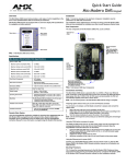
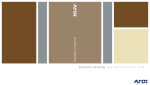
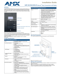
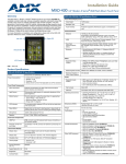
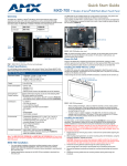
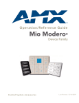
Quick Start Guide
Mio Modero DMS Keypad metallic
Overview
Installation
The Mio Modero DMS device family provides a wide range of control capabilities in the
form of user specified buttons that are functional yet recherché.
Note: To avoid any damage to the electronic component, installation must be
performed in an ESD safe environment. The device and conduit box must have an
Earth ground.
Mio Modero DMS keypads are equipped with an LCD menu display with 8
pushbuttons for navigation and menu selection.
Menu Up
Menu items
The installation section addresses the mounting and wiring of the Mio Modero DMS.
After you have completed the installation you must consult Necessary Device Setup.
Rear Components
The rear components of the Mio Modero DMS (FIG. 2) are as follows:
Menu select
pushbuttons
Ethernet Port
(PoE)
(Front View)
Magnetic Posts
Menu Down
FIG. 1 Mio Modero DMS Device Family
Specifications
Mio Modero DMS (FG2408-01XX) Specifications
Power 12 VDC / PoE:
Maximum power consumption (PoE):
• 5.5 Watts
Maximum startup (rush) current (PoE):
• 150 mA @ 50 VDC
Maximum continuous current (PoE):
• 100 mA @ 50 VDC
Maximum power consumption (DC):
• 5.0 Watts
Maximum startup (rush) current (DC):
• 525 mA @ 13.5 VDC
Maximum continuous current (DC):
• 350 mA @ 13.5 VDC
Front Panel Components:
• LCD display
• 8 pushbuttons
Rear Panel Connectors:
•
•
•
•
Ethernet Port (PoE)
2-pin 3.5 mm mini-Phoenix (female) connector
4 Magnetic Posts
Ground wire
Dimensions (HWD):
(inside of conduit box)
• 6.25 (158.8 mm) x 3.50 (91.4 mm) x 3.93 (99.7 mm)
Supported Fonts:
Only True Type Fonts
2-pin
3.5 mm
mini-Phoenix
(female)
connector
Weight (range):
• Device - .55 lbs (.25 kg)
Operating Environment:
• Operating Temperature: 0° to 40° C (32° to 104° F)
• Storage Temperature: -10° to 60° C (14° to 140° F)
FIG. 2 Mio Modero DMS Rear Components
Mounting:
The Mio Modero DMS is installed in one of three ways:
• Rough-in mounting
• Expansion clips for pressure mounting
• No tabs for brick and mortar mounting
Connections and Wiring
The Mio Modero DMS device is powered either via 12VDC or Power over Ethernet
(PoE). If both the 12 VDC and PoE power sources are connected, by default the
device draws power from the 12 VDC. If the 12 VDC source is disconnected, the PoE
automatically supplies power after a device reboot.
Available Color Schemes:
Gold (GL), Silver (SL)
Included Accessories:
• 2-pin 3.5 mm mini-Phoenix connector (41-5025)
• Conduit box (FG039-11)
• Mounting kit (KA2250-01)
Other AMX Equipment:
• NXA-ENET24PoE: Managed Ethernet Switch, Power
Over Ethernet (FG2178-61)
Dynamic Menu System
Using the KeypadBuilder application available for download from www.amx.com, the
Mio Modero DMS is programmed with a Dynamic Menu System (DMS) that is
navigated via the 8 pushbuttons and LCD display area. See the KeypadBuilder
Instruction Manual for more information on programming Mio Modero DMS devices.
Note: Do not connect power to the Mio Modero DMS until the wiring is complete.
Preparing captive wires for the 2-pin 3.5 mm mini-Phoenix connector
You will need a wire stripper, and flat-blade screwdriver to prepare and connect the
captive wires.
1.
2.
Strip 0.25 inch (6.35 mm) of wire insulation off all wires.
Insert each wire into the appropriate opening on the connector according to the
wiring diagrams and connector types described in this section.
3.
Turn the screws clockwise to secure the wires in the connector.
Note: Do not over-torque the screws; doing so can bend the seating pins and damage
the connector.
Using the PSN NetLinx connector for power
The PWR and GND wires from the 12 VDC power supply must be connected to the
corresponding location on the 2-pin 3.5 mm mini-Phoenix connector (See the
KeypadBuilder Instruction Manual for an illustration).
1.
Insert the PWR and GND wires on the terminal end of a PSN 2-pin 3.5 mm miniPhoenix cable. Match the wiring locations of the +/- on both the power supply
and the terminal connector.
2.
Tighten the clamp to secure the two wires.
3.
Verify the connection of the 2-pin 3.5 mm mini-Phoenix to the power supply.
Using the Ethernet port for power (PoE)
Connect your CAT5/CAT6 Ethernet cable to the port shown in FIG. 2. (See the Mio
Modero DMS & Mio Modero DMS Pinnacle instruction manual for an illustration and
cable pinouts).
Mounting Procedures
FIG. 3 shows the mounting dimensions for the Mio Modero DMS. Reference these
measurements when planning and installing the device. Consult the Mio Modero
DMS & Mio Modero DMS Pinnacle instruction manual for the rough-in and no tab
installation methods.
Expansion Clip Installation
It is recommended that you cutout the surface slightly smaller than what is outlined in
the installation drawings so that you can make any necessary cutout adjustments.
Before you begin, if you are using the 2-pin power connector, verify that the terminal
end of the power cable is not connected to a power source.
1.
2.
If assembled, pull the Mio Modero DMS from the conduit box.
Cut out the surface for the Mio Modero DMS conduit box using the dimensions
shown in FIG. 3. A template is included to help you determine dimensions.
Consult the Mio DMS & Mio DMS Pinnacle instruction manual for setting a Host
Name.
Mio DMS Menu Navigation
Follow these tips to set your device information:
•
•
•
•
•
•
The Up and Down buttons scroll through numerals, upper case and lower case letters.
Accept Char enters the current value and moves the cursor to the right.
Backspace moves the cursor to the left.
Clear removes everything listed.
Abort exits the edit page without keeping changes.
Done accepts changes and returns to the previous page.
Master Connection
1.
Push the button that corresponds to Protected Setup. If you do not have a
password established, the device will not prompt you for one.
2.
Select the button for Master Connection.
3.
Select the button for Connection Mode.
4.
Select the button next to the listed mode to toggle through the available
connection modes:
Connection Modes
Mode
Description
Procedures
Auto
The device connects to the
first master that responds.
This setting requires you set
the System Number, this setting is available in the Master
Connection menu.
Setting the System Number:
1.
Within the Master Connection menu, select the
button for System Number.
2.
To change the System Number from what is
listed, press the button next to the System Number to enter the edit page.
See Mio DMS Menu Navigation for help.
3.
After you have set your System Number and
pressed Done, press Return to finalize your
changes and go back to the Master Connection
page.
URL
The device connects to the
specific IP of a master via a
TCP connection. This setting
requires you set the Master’s
IP.
Setting the Master IP:
1.
Select the button next to More...
2.
Select the button next to Master IP.
3.
To change the Master IP from what is listed,
press the button next to the Master IP number to
enter the edit page.
See Mio DMS Menu Navigation for help.
4.
After you have set your Master IP and pressed
Done, press Return to finalize your changes
and go back to the Master Connection page.
Listen
The device "listens" for the
master to initiate contact. This
setting requires you provide
the master with the device’s
IP.
Confirm device IP is on the Master URL list. You can set
the Host Name on the device and use it to locate the
device on the master. Host Name is particularly useful
in the DHCP scenario where the IP address can
change.
NDP
(UDP)
The device is available via
Nexus Discovery Protocol.
Use the master web interface, NetLinx Studio or
commands to bind the DMS device to the master.
URL
(UDP)
The device connects to the
specific IP of a master via
UDP.
Setting the Master IP:
1.
Select the button next to More...
2.
Select the button next to Master IP.
3.
To change the Master IP from what is listed,
press the button next to the Master IP number to
enter the edit page.
See Mio DMS Menu Navigation for help.
4.
After you have set your Master IP and pressed
Done, press Return to finalize your changes
and go back to the Master Connection page.
Notches are only
required for
expansion clip
installations
FIG. 3 Mio Modero DMS Cutout Installation Dimensions
3.
4.
5.
6.
7.
8.
9.
Thread the CAT5/CAT6, the Earth ground wire and, if necessary, the power
cables through one of the provided breakaway access points on the conduit
box. Leave enough slack in the wiring to accommodate any re-positioning of
the unit. Only use the circular keyholes on the conduit box.
Thread the 2 drywall screws through the 2 locations center on both top and
bottom of the conduit box and then through the expansion clips. Break free the
rough-in mounting tabs at this time by bending back and forth with pliers.
Insert the conduit box and expansion clips into the cutout until the rim of the
conduit box is flush against the wall. Tabs should rest on front of sheetrock.
Tighten the 2 drywall clip sets (screws and clips) until the conduit box is flush
against the wall. Insert the cardboard paint shield into the conduit box and do
not proceed if the Mio Modero DMS will not be installed at this time.
Place the lug of the ground wire on the device and the Earth ground wire
around the provided screw and connect them both to the conduit box. The
device and conduit box must have an Earth ground.
Connect the 2-pin power connector and/or CAT5/CAT6 cables in the back of
the Mio DMS. See FIG. 2 for port locations.
Insert the Mio DMS into the conduit box. You will feel the magnets grab the
side of the conduit box, push until the device is flush to the wall.
Device Setup
The Mio DMS is equipped with firmware pages that allow you to set and configure
various features of the device. Some menu items are compulsory, Necessary Device
Setup, while other items are optional, Optional Device Setup section on page 33
of the instruction manual.
To navigate the pages in the Mio DMS, press More... to view more options within the
selected menu. Press Return to go back a page and accept changes made.
Note: Confirm your NetLinx master has the latest version of Nexus compliant
firmware. The firmware must be UDP and NDP settings compliant (v.323 or higher).
Accessing The Setup Page
If you have not loaded any pages on your Mio DMS device, it will launch the Setup
page by default. Otherwise, press and hold down the Up and Down buttons for 3
seconds.
Necessary Device Setup
The following sections must be set on your Mio DMS.
IP Settings
The configuration of the Mio DMS requires you set the communication protocol. Your
options are either Static or DHCP. Consult the Mio DMS & Mio DMS Pinnacle
instruction manual for setting Static. From the Setup page, follow these steps:
1.
2.
3.
4.
5.
Push the button that corresponds to Protected Setup. If you do not have a
password established, the device will not prompt you for one. The default
password is 1988.
Select the button for IP Settings.
Select the button for DHCP.
In the DHCP page, select the button for DHCP to toggle the protocol between
DHCP and Static.
Select the button for Return to accept that change.
5.
Press the button for More... to view the second page of the Master Connection
menu.
6.
Press the button for Master Port. The default setting for the port is 1319. Press
the button next to the master port number to access the edit page and change
this value.
See Mio DMS Menu Navigation for help.
7.
After you have set your Master Port and pressed Done, press Return to
finalize your changes and go back to the Master Connection page.
If you have enabled password security on your master you need to set the username
and password within the device.
8.
Press the button for Username. If no username has been set, the field is blank.
Press the button that correlates to the blank field just below Username.
See Mio DMS Menu Navigation for help.
9.
After you have set your Username and pressed Done, press Return to finalize
your changes and go back to the Master Connection page.
10. Press the button for More...
11. Press the button for Password. If no password has been set, the field is blank.
Press the button that correlates to the blank field just below Password.
See Mio DMS Menu Navigation for help.
12.
13.
After you have set your Password and pressed Done, press Return to finalize
your changes and go back to the Master Connection page.
Reboot device to confirm changes.
For full warranty information, refer to the AMX Instruction Manual(s) associated with your Product(s).
037-004-2983 8/06
©2006 AMX. All rights reserved. AMX and the AMX logo are registered trademarks of AMX.
AMX reserves the right to alter specifications without notice at any time.
3000 RESEARCH DRIVE, RICHARDSON, TX 75082 • 800.222.0193 • fax 469.624.7153 • technical support 800.932.6993 • www.amx.com
93-2408-04
REV: A