1
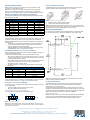
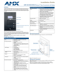
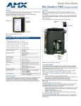
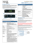
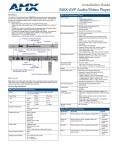
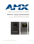
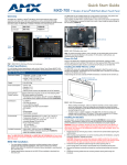
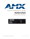
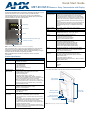
Quick Start Guide
MET-ECOM-D Metreau™ Entry Communicator with Display
Overview
MET-ECOM-D Specifications (Cont.)
The MET-ECOM-D Metreau Entry Communicator with Display (FG2180-05-cc) can be
placed at entry points of homes, condos and hotels to provide audio/video
communications with anyone at a door or gate - all over IP. Any AMX Modero
intercom-enabled touch panel can interface with the Metreau Entry Communicator
and allow residents to open doors, gates and more.
Rear Panel
Components (Cont.):
• Status LED: Green LED provides an indication of both the
system status and communication status with the target Master.
1 blink every 5 seconds indicates there is currently active
communication between the Metreau unit and a target Master.
• 2 Multi-Purpose I/Os (5V): 2-channel binary I/O ports for contact
closure with each input being capable of voltage sensing. Input
format is software selectable with interactive power sensing for
IR ports.
• 2 Low Voltage Relays (1A/24VDC contact): 2-channel single-pole
single throw relay ports with each relay being independently
controlled and supporting up to 2 independent external relay
devices.
Dimensions (HWD):
5.364” x 3.594” x 1.559” (13.62 cm x 9.13 cm x 3.96 cm)
OLED display
Video Camera
Speaker
Weight:
0.90 lbs (0.408 kg)
Environmental:
• Operating Environments: 32º - 104º F (0º - 40º C)
• Storage Environments: 22º - 140º F (-30º - 60º C)
Mounting:
The MET-ECOM-D is installed in several ways:
• 4 screws for hard surface mounting
• 2 expansion clips for pressure mounting
• Using the optional Surface Mount Box
Colors Available:
•
•
•
•
•
•
Included
Accessories:
Installation Kit (KA2180-01) - includes front mount flange,
4 installation screws (#4-40 x 3.12), 2 Phoenix connectors
(female, 3.5mm) and a Ferrite clip.
Other AMX
Equipment:
• PS-POE-AF Power-over-Ethernet power supply (FG423-80)
• NXA-ENET24 Managed Ethernet Switch (FG2178-60)
• NXA-ENET24PoE Managed Ethernet Switch, Power Over
Ethernet (FG2178-61)
• Conduit Box Assembly ( FG039-12)
• SMB-MET-ECOMS-B/P Surface Mount Box - Black or Primed for
painting (FG039-14-B/P)
Certifications:
•
•
•
•
Dual Color LED Status Bar (Yellow / Red)
Pushbutton (Doorbell)
Microphone
FIG. 1 MET-ECOM-D Metreau Entry Communicator with Display
Refer to the Metreau Entry Communicators Operation/Reference Guide (available
online at www.amx.com) for additional installation details and instructions on
positioning the integrated video camera, using the Configuration Manager, using the
full-duplex intercom, and NetLinx Programming information.
Note: The MET-ECOM-D is intended for installation in interior or protected
environments.
Product Specifications
MET-ECOM-D Specifications
Power:
• PoE powered – no local Power Supply needed
• IEEE 802.3af Compliant
OLED Display:
•
•
•
•
•
4-bit Gray Scale
1.6” Diagonal Display
180° Viewing Angle
2000:1 Contrast Ratio
Unit stores up to 50 .bmp images
Integrated Color
Video Camera:
•
•
•
•
•
•
QVGA 320 x 240
Supports Motion JPEG (MJPEG) and H.263 codecs.
Horizontal viewing angle: 46°
Vertical viewing angle: 33°
Adjustable Viewing Angle for Camera: 42°
Frame Rate (FPS) of Mjpeg Stream: Variable - depends on
Dynamic Image configuration (standard or accelerated), as well
as on network limitations such as traffic or bandwidth.
Note: For the highest possible frame rate (up to 30 fps), use
accelerated dynamic images, as described in the Creating a New
Dynamic Image section of the Metreau Entry Communicators
Operation/Reference Guide.
Speaker:
• 8 Ohm, 2W
• 80dB SPL (sound pressure level at 1 meter)
• Meets G.711 sound standard
Microphone:
• -40 dB sensitivity, built-in echo cancellation (telephone quality)
• Full duplex communication
• VoIP Telephony
Rear Panel
Components:
• Camera Viewing Angle Adjustment
• Ethernet Port - 10/100 Ethernet with PoE. LEDs show
communication activity, connection status, speeds, and mode
information:
SPD (speed) - Green LED lights On when the connection speed
is 100 Mbps and turns Off when the speed is 10 Mbps.
L/A (link/activity) - Orange LED lights On when the Ethernet
cables are connected and terminated correctly, and blinks when
receiving Ethernet data packets.
• ID/Reset pushbutton: Push to set the NetLinx ID (Device only)
assignment for the device. Push and hold for at least 10 seconds
to reset to factory default settings.
Black MET-ECOM-BK (FG2180-05-BK)
White MET-ECOM-WH (FG2180-05-WH)
Polished Brass MET-ECOM-PB (FG2180-05-PB)
Antique Brass MET-ECOM-AB (FG2180-05-AB)
Stainless Steel MET-ECOM-SS (FG2180-05-SS)
Brushed Pewter MET-ECOM-BP (FG2180-05-BP)
FCC Class B
CE
IEC60950
RoHS
Rear Panel Components
FIG. 2 shows the location of the rear panel components for the MET-ECOM-D.
Camera Viewing
Angle Adjustment
Mounting Slots
(2 on each side)
ID/Reset pushbutton
STATUS (green LED)
Ethernet Connection
2 Multi-Purpose I/Os (5V)
2 Low Voltage Relays
(1A/24VDC contact)
Mounting Clip
FIG. 2 Metreau Entry Communicator (rear panel)
Wiring and Connections
Ferrite Installation (Required)
Note: To avoid any damage to the electronic component, installation must be
performed in an ESD safe environment.
Note: Do not connect power to the MET-ECOM-D until the wiring is complete.
After you have completed the installation, consult the Using the Configuration
Manager section of the Metreau Entry Communicators Operation/Reference Guide.
The MET-ECOM-D comes with a Cat5 Suppression Ferrite that must be clipped
around the Ethernet cable, inside the back box (no tools required).
Ethernet 10/100 Base-T RJ-45 Wiring Configuration
The table below describes the pinouts, signals, and pairing for the Ethernet 10/100
Base-T connector and cable.
1
2
3
(complete)
Ethernet Pinouts and Signals
Pin
Signals
Connections
Pairing
Color
1
TX +
1 --------- 1
1 --------- 2
White-Orange
2
TX -
2 --------- 2
3
RX +
3 --------- 3
4
no connection
4 --------- 4
Blue
5
no connection
5 --------- 5
White-Blue
6
RX -
6 --------- 6
Green
7
no connection
7 --------- 7
White-Brown
8
no connection
8 --------- 8
Brown
Orange
3 --------- 6
White-Green
FIG. 4 Installing the CAT5 Suppression Ferrite
1.
2.
Release the latch to open the plastic enclosure.
Insert the Cat5 cable and close the enclosure.
Note: When positioning the Ferrite clip inside the back box, place the bottom of the
clip flat against the back inside surface of the back box, to allow sufficient room for the
MET-ECOM-D unit. See the Operation/Reference Guide for details.
Mounting Specifications
FIG. 5 shows the recommended cutout for the Metreau Entry Communicators Wall
Box. Use these dimensions for wall surface installations using expansion clips.
The MET-ECOM-D uses CAT5/CAT6 wire via the Ethernet port for PoE power.
PoE (Power Over Ethernet)
Use the PS-POE-AF Power over Ethernet Injector (FG423-80) to simplify wiring and
installation by eliminating the need for an AC outlet at each point of installation.
Note: The MET-ECOM-D can be placed up to approximately 330’ (100 meters) from
the PoE Injector.
• If used with a non PoE-capable Ethernet switch (such as the NXA-ENET24),
then an optional PS-POE-AF Power-over-Ethernet (PoE) power supply is
required to provide power to the MET-ECOM-D.
• If the MET-ECOM-D is used with a PoE-capable Ethernet switch (such as the
NXA-ENET24PoE), then no PoE Injectors are required.
Input/Output (I/O) Port: Connections and Wiring
The I/O port responds to either switch closures, voltage level (high/low) changes, or it
can be used for logic-level outputs.
A contact closure between the GND and an I/O port is detected as a Push.
• When used for voltage inputs, the I/O port detects a low signal (0 - 1.5 VDC) as
a Push, and a high signal (3.5 - 5 VDC) as a Release (this IO port uses 5V logic
but can handle up to 12V without harm).
• When used for outputs, the I/O port acts as a switch to GND and is rated for 200
mA @ 5 VDC. This device can use up to 2 I/O ports (see table below).
• The PWR pin provides +5 VDC @ 200 mA.
• The GND connector is a common ground and is shared by all I/O ports (see
table below).
I/O Port Wiring Specifications
Pin
Signal
1
5 VDC
Function
PWR
2
I/O 2
Input/Output
3
I/O 1
Input/Output
4
GND
Signal GND
Connecting The Device via I/O
When connecting the I/O port, the GND on the MET-ECOM-D must be connected to
the ground of the I/O device, e.g., a master or any third party I/O device.
You can connect up to 2 independent external relay devices to the Relay connectors
on the MET-ECOM-D.
• Connectors labeled A are for common; B are for output.
• Each relay is isolated and normally open.
I/O and Relay Connectors - Pinout Configurations
FIG. 3 shows the pin configuration on the I/O and Relay ports.
1
B
A
B
A
I/Os
+5V
Relays
GND
Note: Refer to the Metreau Entry Communicators Operation/Reference Guide for
additional installation details and drawings.
Positioning the Camera
Relay Port: Connections and Wiring
2
FIG. 5 Recommended Cutout for Wall Box
2
The Metreau Entry Communicators feature a Camera Viewing Angle Adjustment
slider on the rear panel of the unit that allows you to adjust the viewing angle
horizontally from -15° to 15° (see FIG. 2).
The Camera Viewing Angle Adjustment slider is intended to be used at the time of
installation. It is not intended to be used for regular periodic adjustments. Once a final
installation location has been established, use the Camera Viewing Angle Adjustment
slider to set the desired camera angle, then finalize the installation.
Additional Documentation
Refer to the Metreau Entry Communicators Operation/Reference Guide (available at
www.amx.com) for additional installation/setup details, information on using the
Configuration Manager, the NetLinx module and Programming information.
1
FIG. 3 I/O and Relay connectors
Note: Do not use the relays on this unit for "secure" applications such as door and
gate releases. For security reasons, an external relay box put in a secure location will
work better for these devices.
For full warranty information, refer to the AMX Instruction Manual(s) associated with your Product(s).
2/14
©2014 AMX. All rights reserved. AMX and the AMX logo are registered trademarks of AMX.
AMX reserves the right to alter specifications without notice at any time.
3000 RESEARCH DRIVE, RICHARDSON, TX 75082 • 800.222.0193 • fax 469.624.7153 • technical support 800.932.6993 • www.amx.com
93-2180-05
REV: J