1
M-216 OPERATOR’S MANUAL
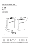
M-216
Wireless
Microphone
Transmitter
357 West 2700 South • Salt Lake City, Utah 84115 • Phone: (800) 496-3463 • Fax: (801) 484-6906 • http://www.comtek.com
TABLE OF CONTENTS
Introduction ...........................................................
1
Setup ...............................................................................
2
Controls ..................................................................
3
Battery Removal / Replacement ......................................
4
Battery Charging ......................................................
5
Auxiliary Audio Input Operation ...................................
6-7
Snap-On Belt Clip .................................................
7
Frequency Selection ..............................................
8
Frequency Information .........................................
9-10
Optional Accessories ............................................
11
Options .................................................................
12
HH-185 ...................................................................
13
Trouble Shooting ..................................................
14-15
Specifications .........................................................
16
Warranty and Service ..................................................
17
© 2013 COMTEK® All rights reserved.
Printed in the U.S.A. 04-15-2013
INTRODUCTION
M-216
Wireless
Microphone
Transmitter
T
he M-216 wireless microphone transmitter
offers the ultimate performance and
versatility for assistive listening, language
interpretation, tour guide presentations,
personal communication, and for other
personal remote transmission situations.
The M-216 incorporates the latest digital and
analog technologies to produce low residual
noise, wide dynamic range, and extended
frequency response rendering the most natural
sound possible from a wireless microphone.
The transmitter’s microcontroller automatically
sets the modulation deviation, companding or
non-companding audio processing when
corresponding channels are selected. Because
of this comprehenive feature, this versatile
transmitter can transmit on 19 high fidelity
companded channels or 38 standard
channels ensuring compatibility with
receivers conforming to regulations
regarding Low Power Radio Service
(LPRS) transmissions in the 216-217 MHz
band under Part 95 of the FCC regulations.
Page 1
M-216 SETUP
Setup
a. Check to ensure that the M-216 transmitter’s radio frequency channel is
the same as the associated COMTEK receiver’s channel. (Channels are
indicated by the rotary channel selector switches on the back of the
transmitter. See page 3.)
b. Open the battery door cover on the transmitter (see page 4) and
insert a new nine volt alkaline battery (Eveready E522 or equivalent). This
type of battery will offer up to 30 hours of operation. Replace the battery before
every use if the demand for fail-safe operation outweighs battery cost. The use of
carbon batteries is not recommended.
NOTE: If a rechargeable battery is to be used, ensure that it has been
allowed to charge at least 14 hours to bring it to full charge (see page 5 for
battery charger instructions).
c. Connect the microphone to the transmitter by inserting the microphone
plug into the receptacle on the top of the transmitter. The transmitter is
operating when the transmitter power switch is turned on and the battery
status on indicator illuminates.
NOTE: The 36-inch microphone cord also functions as part of the
transmitter’s antenna system. For optimum performance, this cord
should be fully extended. Coiling or bunching the microphone
cord may reduce the range of the transmitter. The transmitter
should be carried by the snap-on belt clip (included) or in a pocket
or belt-clip pouch.
d. In a situation where an extremely loud voice or a very soft voice is used, it
is necessary to adjust the audio input gain control while observing the audio
“voice” level modulation indicator. A full bright LED indicates full audio
compression at 100% modulation. For best performance, the audio input
gain should be adjusted for some low level LED luminescence during
normal audio levels with occasional full bright peaks indicating 100%
modulation.
Page 2
M-216 CONTROLS
n OPTIONAL COMPAND AUTO / OFF SWITCH: This switch
overrides the automatic selection of the companded channels for
non-companded operation.
(This switch should remain in the “Auto” position.)
o CHANNEL SWITCHES: These rotary
switches are set to the same channel as the
receiver. Actual frequency of operation
must agree with the receiver.
(See page 10 for frequency selection chart.)
p BATTERY COMPARTMENT: The
battery compartment features a hinged
battery cover and an alignment system that
ensures proper battery polarity. Battery
installation and removal is facilitated by simply
manipulating the bottom of the battery.
q AUXILIARY AUDIO INPUT JACK:
Allows transmitter to use line level, earphone
level, or fixed AUX as an audio source.
r AUDIO “VOICE” MODULATION INDICATOR:
This indicator is used in making adjustment with the
Audio Input Gain Control.
s MIC / ANTENNA JACK: This jack accepts an
electret type microphone having a 36” long cord with a
micro-mini 2.5 mm mono plug. This jack is also used
for the R.F. output for the screw-in whip antenna
when only the auxiliary audio input is used.
t POWER / BATTERY STATUS INDICATOR: This LED indicator will illuminate
continuously when the unit is on indicating normal operation. When the battery voltage
drops below 6 volts, the LED will flash rapidly indicating that a new battery is needed.
u OPTIONAL MIC MUTE SWITCH: This switch turns off the microphone without
turning off the transmitter carrier.
v AUDIO INPUT GAIN CONTROL: This is a microphone and AUX level input gain
control. This control is used with the “Voice” modulation indicator.
w ON / OFF SWITCH: This switch turns the transmitter on and off.
Page 3
M-216 BATTERY REMOVAL / REPLACEMENT
Low Battery Indicator
The LED on the top of the transmitter
indicates the status of the battery as
well as indicating that the unit is turned
on. When turned on, the LED illuminates.
If the battery is low the green LED will
blink rapidly warning that the battery will
soon be dead. Replace a low battery
immediately.
Battery indicator LED
Battery Removal / Replacement
Pull back battery door latch and allow battery
cover door to spring open. To remove battery,
simply manipulate the bottom of battery out of
the compartment and remove.
To insert battery, face battery
with negative terminal in line with
large hole in battery compartment,
press battery into compartment and close
battery door until it snaps shut. Note: It is not
possible to put battery in backwards.
Page 4
M-216 BATTERY CHARGING
Battery Charging
1. Make sure that a seven cell 9 volt Ni-MH rechargeable
battery is used with a minimum of 200 mAh capacity.
(Alkaline batteries must not be charged.)
TANT
IMPOR
2. Make sure the M-216 is turned OFF.
3. Note that the red charging indicator on the charger is ON when the M-216
is plugged into the charger through the auxiliary audio input jack.
4. When using the NBC 9-2C charger allow the battery to charge for 14 hours
for a full charge. Unit must then be unplugged. When using the
NBC 9-3-1 digital fast charger the charger will automatically end the
charge cycle and the red LED will change to green. With the NBC 9-3-1
charger the unit may be left in the charger until the unit is used.
5. Periodically open the battery compartment on stored COMTEK units to
check for battery leakage. If a battery is leaking, it must be discarded,
and the battery compartment must be cleaned or returned to COMTEK’s
service department for repairs.
NBC 9-2C
14-hour charger
NBC 9-3-1
digital fast charger
Page 5
M-216 AUXILIARY AUDIO INPUT OPERATION
Auxiliary Audio Input Operation
The M-216 transmitter may transmit from a
variety of audio sources such as digital media
players, or any audio device having an auxiliary
or earphone level audio signal.
The auxiliary input cable supplied with the
M-216 transmitter (CB-36 ST) will operate
with any device having a mini 3.5 mm
jack, stereo or mono, and with line level or
earphone level output.
To accommodate a variety of specialty
applications, auxiliary input cables
with RCA phono plug, 1/4” audio
phone plug, and XLR connectors are
available from COMTEK.
Setup
a. Plug the micro-mini
screw-lock whip antenna
into the top center jack
(mic/ant.) of the M-216
transmitter. The whip
antenna should be in a
vertical position away from
any metallic objects to ensure
maximum range performance.
b. Connect the proper auxiliary input cable to the
audio source. Connect the right-angle mini plug end of the
auxiliary input cable into the “AUX” input jack of the M-216 transmitter.
Note: Check to ensure that the audio source is a line level, earphone level,
or fixed AUX level output.
(continued)
Page 6
M-216 SNAP-ON BELT CLIP
c. Turn on the transmitter with program from the audio source being fed to
the transmitter. Observe the audio “voice” level modulation indicator. A full
bright LED indicates full audio compression at 100% modulation. For best
performance, the audio input gain should be adjusted for some low level
LED luminescence during normal audio levels with occasional full bright
peaks indicating 100% modulation.
d. When using the auxiliary audio input with the microphone plugged into
the transmitter, priority should be given to the microphone gain adjustment.
The mixing balance between the auxiliary audio and the microphone should
be made with the volume control of the auxiliary audio source.
Note: The optional microphone mute switch only affects the
microphone. It does not affect the auxiliary audio input.
M-216 SNAP-ON BELT CLIP (Included)
STEP 2:
Rotate belt clip down onto case. Apply
pressure on both sides of clip, snapping
clip retainers into slots.
Belt clip installation
Clip retainer
STEP 1:
Hook belt clip
retaining lip over
front case ridge.
Retainer slot
Belt clip removal indent
Belt clip removal
Flex out and pull down with your
thumb or a large coin (quarter) to
unsnap belt clip from case.
Page 7
M-216 FREQUENCY SELECTION
Frequency Selection (216-217 MHz)
The M-216 transmitter can operate on one of 57 available frequencies
between 216 MHz and 217 MHz. COMTEK’s channel designations indicate
both non-companded standard channels and high-fidelity, companded
channels. Channels 1-40 are non-companded channels offering compatibility
with other manufacturers’ receivers. Channels 41-60 are high-fidelity,
companded channels for use with COMTEK receivers. COMTEK transmitters
automatically transmit the proper mode when set to channels 1-40 for
non-companded or 41-60 for companded channels.
Note: The optional compand switch should remain in
Compand switch
the “Auto” position.
(optional)
After you have determined the channel on which
you are going to operate, position the two rotary
switches to indicate the channel. The left rotary
switch is for tens and the right rotary switch is for
ones, e.g. to select channel 41 (216.0250 MHz),
position the left rotary switch to point to 4 (X10),
and position the right rotary switch to point to 1 (X1).
Refer to frequency charts on pages 9 and 10 for selectable frequencies.
Multiple Channel Operation
When multiple transmitters are broadcasting in the same immediate area
(within 100 feet), the RF signals will “mix” together generating additional
signals. If these product frequencies are too close to a frequency which you are
using, you will experience intermodulation interference. This condition is
common to all radio receivers to some extent.
Simultaneous operation of more than three channels requires frequency
coordination to avoid intermodulation interference, which could result in
poor or unusable performance.
To avoid this type of interference, you should select frequencies from one of
the standard groups (see frequency group charts on page 10), or use COMTEK’s
frequency selection software (www.comtek.com/support.html) to determine
appropriate frequencies or contact COMTEK to obtain a free copy.
Page 8
M-216 FREQUENCY INFORMATION
Non-Companded Channels
High-Fidelity Companded Channels
For use with COMTEK and other manufacturers
(Educational Standard)
For use with COMTEK equipment only
(Companded)
CHANNEL
FREQUENCY
CHANNEL
01
02
03
04
05
06
07
08
09
10
11
12
13
14
15
16
17
18
21
22
23
24
25
26
27
28
29
30
31
32
33
34
35
36
37
38
39
40
FREQUENCY
(SWITCH POSITION)
(SWITCH POSITION)
216.0125 MHz
216.0375 MHz
216.0625 MHz
216.0875 MHz
216.1125 MHz
216.1375 MHz
216.1625 MHz
216.1875 MHz
216.2125 MHz
216.2375 MHz
216.2625 MHz
216.2875 MHz
216.3125 MHz
216.3375 MHz
216.3625 MHz
216.3875 MHz
216.4125 MHz
216.4375 MHz
216.5125 MHz
216.5375 MHz
216.5625 MHz
216.5875 MHz
216.6125 MHz
216.6375 MHz
216.6625 MHz
216.6875 MHz
216.7125 MHz
216.7375 MHz
216.7625 MHz
216.7875 MHz
216.8125 MHz
216.8375 MHz
216.8625 MHz
216.8875 MHz
216.9125 MHz
216.9375 MHz
216.9625 MHz
216.9875 MHz
41
42
43
44
45
46
47
48
49
51
52
53
54
55
56
57
58
59
60
61
62
63
64
65
66
67
68
69
71
72
73
74
75
76
77
78
79
70
Page 9
216.0250 MHz
216.0750 MHz
216.1250 MHz
216.1750 MHz
216.2250 MHz
216.2750 MHz
216.3250 MHz
216.3750 MHz
216.4250 MHz
216.5250 MHz
216.5750 MHz
216.6250 MHz
216.6750 MHz
216.7250 MHz
216.7750 MHz
216.8250 MHz
216.8750 MHz
216.9250 MHz
216.9750 MHz
216.0250 MHz
216.0750 MHz
216.1250 MHz
216.1750 MHz
216.2250 MHz
216.2750 MHz
216.3250 MHz
216.3750 MHz
216.4250 MHz
216.5250 MHz
216.5750 MHz
216.6250 MHz
216.6750 MHz
216.7250 MHz
216.7750 MHz
216.8250 MHz
216.8750 MHz
216.9250 MHz
216.9750 MHz
M-216
M-216
216 MHz
NON-COMPANDED
FREQUENCY GROUPS
216 MHz
COMPANDED
FREQUENCY GROUPS
Compatible with COMTEK
and other manufacturers
For COMTEK
equipment only
GROUP 1
GROUP A
CHANNEL
FREQUENCY
CHANNEL
FREQUENCY
1
9
15
24
31
36
216.0125 MHz
216.2125 MHz
216.3625 MHz
216.5875 MHz
216.7625 MHz
216.8875 MHz
41
44
51
55
60
216.0250 MHz
216.1750 MHz
216.5250 MHz
216.7250 MHz
216.9750 MHz
GROUP B
GROUP 2
CHANNEL
FREQUENCY
CHANNEL
FREQUENCY
4
10
14
32
35
40
216.0875 MHz
216.2375 MHz
216.3375 MHz
216.7875 MHz
216.8625 MHz
216.9875 MHz
42
49
53
58
216.0750 MHz
216.4250 MHz
216.6250 MHz
216.8750 MHz
GROUP C
GROUP 3
CHANNEL
FREQUENCY
CHANNEL
3
5
12
22
38
216.0625 MHz
216.1125 MHz
216.2875 MHz
216.5375 MHz
216.9375 MHz
43
46
51
57
GROUP D
FREQUENCY
216.1250 MHz
216.2750 MHz
216.5250 MHz
216.8250 MHz
GROUP 4
CHANNEL
FREQUENCY
CHANNEL
FREQUENCY
17
23
30
34
39
216.4125 MHz
216.5625 MHz
216.7375 MHz
216.8375 MHz
216.9625 MHz
44
47
54
59
216.1750 MHz
216.3250 MHz
216.6750 MHz
216.9250 MHz
Page 10
M-216 OPTIONAL ACCESSORIES
Optional Accessories
1. NBC 9-2C Battery charger
2. NH 9-200 Rechargeable batteries
3. P-1 Universal pouch
4. BC-216 Snap-on belt clip
(supplied with M-216)
5. LW-216 Whip antenna
(supplied with M-216)
6. HM-100C Headworn
unidirectional electret
microphone
7. HH-185 Handheld
microphone boom adaptor
8. TM-10 Conference table
microphone adaptor
9. SM-185RT Unidirectional
electret condenser
microphone
Auxiliary Audio Input Cords
10. CB-36 ST Stereo mini 3.5 mm
(supplied with M-216)
11. CB-36 RCA Phono plug
(optional)
12. CB-36 ST 1/4 Stereo 1/4”
(optional)
13. CB-36 XLR XLR-F 3 pin connector
(optional)
Page 11
M-216 OPTIONS
SLW-216
short whip
antenna
(supplied)
Option P-7
The optional P-7 M-216 transmitter may be body
worn on a belt with the snap-on belt clip or may be
inserted in the optional MBS-216 mounting bracket
stand for easy system setup. The MBS-216 is
ideal for on location program monitoring for
large area coverage.
Auxiliary
audio
input
jack
BNC
type
connector
MBS-216
mounting bracket
stand
(optional)
Included
belt clip
CB-36 XLR
(supplied)
Option 1
The optional microphone mute switch allows the
speaker’s voice from the M-216 transmitter
to be muted while the aux input audio
remains on. When the microphone
switch is turned back on the aux audio
level is automatically lowered 6 dB
to prioritize the speaker’s voice.
Page 12
Microphone mute
switch
M-216 / HH-185
Optional HH-185 Handheld Boom Microphone
For added versatility, the HH-185 cardioid boom microphone allows the
standard M-216 transmitter to be used as a handheld “pass-around”
wireless microphone. The HH-185 microphone gain is adjusted with the
gain control on the M-216 transmitter. This allows the user to optimize the
sensitivity of the microphone when it is used in a high background noise
environment. The HH-185 boom incorporates a unique integral antenna
design so no external antenna is required while still maintaining full
transmission.
The HH-185 boom microphone can also be used
with the PR-216 personal receiver equipped with
the Option 2P for auditory assistance applications.
When plugged into the PR-216 personal receiver,
the gain of the boom microphone can be independently
adjusted to a gain level sufficient to selectively pick
up a single voice in a group. This isolates a
particular voice while receiving
a voice signal from the M-216
wireless microphone
transmitter.
Simple
“push and
turn”
installation
M-216
Transmitter
PR-216
Personal Receiver
Page 13
M-216 TROUBLE SHOOTING
Batteries and Battery Charging
If...
Test indicator lamp doesn’t illuminate when units are turned on...
Then...
• If rechargeable batteries are used, ensure that they have been allowed to
charge at least 14 hours to a full charge. Verify that the charging indicator
lamps are illuminated when the charging plugs are plugged into the units.
The units’ power switches must be in the “off ” position for charging.
• If the test indicator lamp still does not illuminate after a full charge, verify
that the system is operational by using a new alkaline battery. If the system
is operational with alkaline batteries, the rechargeable batteries or charger
may need to be replaced.
• The M-216 transmitter must be returned to COMTEK for service if the test
indicator lamp does not illuminate when new alkaline batteries are used.
Transmitter Audio Problem
If...
There is no visual indication on the “voice” modulation level indicator
when speaking into the microphone of the M-216 transmitter...
Then...
• Turn up the microphone gain setting clockwise until the voice
modulation indicator illuminates with speech level.
• Make sure the optional muting switch is in the “mic on” position.
• Check the CM-183RT microphone for a broken or frayed microphone
cord that may cause intermittent operation.
• Test the modulation indicator with the auxiliary audio input using a line
level signal and the CB-36ST auxiliary audio input cable to verify normal
operation. If the auxiliary audio input activates the voice modulation
indicator normally, the CM-183RT microphone may need to be repaired
or replaced.
• The M-216 transmitter must be returned to COMTEK for service if the
auxiliary input test does not activate the voice modulation indicator.
Page 14
M-216 TROUBLE SHOOTING (Continued)
Possible Causes of Noisy Audio
1. Excessive Distances
Operating at a distances greater then 200 ft. may cause excessive noise.
2. Channel Selection
Operating on non-companded channels 1-40 will inherently have much
noisier characteristics. Companded channels 41-60 will produce the
best signal-to-noise performance.
3. Gain Problem
Check the microphone gain setting on the M-216 transmitter for normal
operation with the “voice” modulation indicator (See page 2 section d.)
Low modulation will render poor signal-to-noise ratio.
4. Channel Interference
Monitor the PR-216 receiver with the headphone plugged in and with
the transmitter turned “OFF” on the channel that the transmitter is
tuned to. Check the PR-216 receiver status indicator LED. If a steady
slow flash is indicated, the receiver is receiving a signal on the transmitter
channel and a new channel must be selected. If the status indicator LED
on the PR-216 receiver is illuminated continuously and noise is no
longer heard, then the channel is clear and channel interference is not
the problem.
5. Transmitter Power and Receiver Sensitivity
Check the M-216 transmitter for normal R.F. power and the PR-216
receiver for normal R.F. sensitivity. This can easily be done by range
checking the receiver and transmitter with the microphone cord antenna
removed from the transmitter. Turn on the transmitter and place it on a
non-metallic table. Turn on the receiver and plug in the headphone cord
into the receiver like it would normally be used. Then walk away from
the transmitter while listening for noise build-up just before the squelch
action takes place. A distance of 30-50 ft. should be obtained. Use
companded channels 41-60 for this test. If the receiver and transmitter
do not pass this test, both receiver and transmitter must be returned to
COMTEK for service.
Page 15
M-216 SPECIFICATIONS
Audio Input:
• Microphone input impedance for electret
type microphone - 3000 ohm
• Aux/Line input impedance - 10 k ohm at
0 dB nominal
Connectors:
Microphone - Micro-mini mono 2.5 mm
Auxiliary - Mini stereo 3.5 mm
Audio: Tip and sleeve
Battery Charging: + Tip, _ sleeve
9 volt DC input: + Ring, _ sleeve
(with current limiting)
Out-of-Band Emissions:
Better than 45 dB below carrier
R.F. Stability:
20 ppm XTL controlled
Digitally synthesized
RF Power Output:
10 mW to antenna system
Antenna System:
Body-worn microphone cord,
or whip plugged directly into
microphone connector when
auxiliary input is used
Controls and Indicators:
• Synthesized channel selection switches
• Power On/Off switch
• Optional microphone muting switch
• Audio input gain control
• Power/Battery status indicator
• Audio (voice level) modulation indicator
• Companded auto/off switch (optional)
Frequency Response:
80 Hz to 10 kHz
Audio Distortion:
Less than 1% at 80% modulation
Current Drain:
18 mA constant current
Battery:
• 9 volt alkaline Eveready 522
or equivalent for up to 30 hours
of operation
• 9 volt Nickel-Metal Hydride
rechargeable battery for up to
10 hours of operation
Dimensions:
1 1/16" x 2 1/4" x 3 1/2"
(27 mm x 57 mm x 89 mm)
Modulation Limiter:
Soft compressor with 30 dB linear overload
protection, attack time - less than 1 ms,
recovery time - 10 ms
Weight:
5 ounces (140 grams)
FCC Compliance:
Certification under Part 95
Frequency Modulation:
• 10 kHz deviation
Operating Radio Frequency:
ity: 57 synthesized frequencies in the 216-217 MHz
LPRS band under FCC part 95
NOTE: Specifications subject to
change without notice or
obligation
Page 16
M-216 WARRANTY AND SERVICE
Warranty
COMTEK transmitters and receivers are warranted to be free from defects in
workmanship and material under normal stand-alone use and conditions for a
period of two years from date of original purchase. Items such as headphones,
earphones, neckloops, and cords are warranted to be free from defects in
workmanship and material for a period of 90 days from the date of original
purchase. Batteries are not covered by this warranty. Damage due to
abnormal use, extreme conditions, misuse, use of the product as a component
of another product, ill treatment and unauthorized modification and repairs
are not covered by this warranty. COMTEK is not liable for any consequential
or punitive damages arising out of any failure of the equipment to perform as
intended. COMTEK shall bear no responsibility or obligation with respect to
the manner of use of any equipment sold by it. COMTEK SPECIFICALLY
DISCLAIMS AND NEGATES ANY WARRANTY OF MERCHANTABILITY
OR FITNESS OF THE PRODUCT FOR A PARTICULAR PURPOSE
INCLUDING, WITHOUT LIMITATION, ANY WARRANTY THAT THE USE
OF SUCH EQUIPMENT FOR ANY PURPOSE WILL COMPLY WITH
APPLICABLE LAWS AND REGULATIONS.
Service Policy
Warranty repairs must be done by COMTEK. Only factory technicians are
authorized to perform warranty service on the M-216 transmitter. Before
returning the M-216 for service, a Return Authorization Number should
be obtained from the service department by calling 1-800-496-3463 or
1-801-466-3463. Return the unit to the factory with the original or comparable
packing. COMTEK will pay for insurance and ground return shipping costs in
the United States for all warranty service.
357 West 2700 South • Salt Lake City, Utah 84115 • Phone: (800) 496-3463 • Fax: (801) 484-6906 • www.comtek.com
E-mail: [email protected]
357 West 2700 South • Salt Lake City, Utah 84115 • Phone: (800) 496-3463 • Fax: (801) 484-6906 • http://www.comtek.com