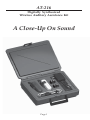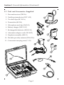
1
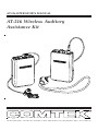
AT-216 OPERATOR’S MANUAL AT-216 Wireless Auditory Assistance Kit 357 West 2700 South • Salt Lake City, Utah 84115 • Phone: (800) 496-3463 • Fax: (801) 484-6906 • http://www.comtek.com Table of Contents Section 1: General Information 1.1 Purpose of Equipment 1.2 Unit and Accessories (Supplied) 1.3 PR-216 Controls, Connectors and Indicators 1.4 M-216 Controls, Connectors and Indicators Section 2: Operation 2.1 Operating the System 2.2 Optional EnviroMic 2.3 Connection Possibilities 2.4 Frequency Selection 2.5 Battery Removal / Replacement 2.6 Belt Clip Installation / Removal Section 3: Battery Charger Section 4: Frequency Chart / Frequency Groups Section 5: Optional Accessories Section 6: Trouble Shooting Section 7: Care and Maintenance Section 8: Warranty and Service © 2001 COMTEK® All rights reserved. Print Release Date 08-05-2001-B AT-216 Digitally Synthesized Wireless Auditory Assistance Kit A Close-Up On Sound Page 1 Section 1 General Information Introduction Thank you for purchasing the COMTEK AT-216 FM wireless auditory assistance system. For over 30 years, COMTEK FM systems have successfully proven to be an effective way to help the hearing-impaired individual in difficult listening situations. The new AT-216 FM system combines the experience and integrity of COMTEK’s preceding models with the advantages of today’s digital technology. Plus, the all new rugged packaging design of the receiver and transmitter ensures that this system will hold up to the rigors of every day use. This product is made in the U.S.A. with strict quality control procedures to ensure your satisfaction. A careful reading of this quick-reference manual will acquaint you with the characteristics of the AT-216 system and ensure ease of operation. 1.1 Purpose of Equipment The AT-216 system functions as a remote microphone for the user, overcoming the greatest listening problems for the hearing-impaired: • High levels of background noise • Reverberation effects • Distance between the speaker and listener. The AT-216 system enables persons with impaired hearing to take part in activities at school, home, work, and play. In addition to a hearing aid, the user wears the personal receiver and the neckloop retransmit device. The PR-216 personal receiver picks up the voice of the person wearing the M-216 transmitter, and the neckloop then retransmits it to the hearing aid for close-up sound. If no hearing aids are used, the receiver may also be used with headphones instead of the neckloop. Now the person with impaired hearing has a direct link to the speaker at greater distances for improved listening, clarity, and better understanding. Page 2 Section 1 General Information (Continued) 1.2 Unit and Accessories Supplied 1. Personal receiver (PR-216) 2. Neckloop transductor (NTC-102) 3. Two belt clips (BC-216’s) 4. Transmitter (M-216) 5. Microphone and clip (SM-183) 6. Battery charger (NBC 9-2C) 7. Rechargeable batteries (NH9-150) 8. Attenuator adaptor cord (CB-36ST) 9. Earphone assembly (SM-N) 10. Flexible specialty antenna (FWA-216) 11. Convenient carrying case (C-111) Page 3 Section 1 General Information (Continued) 1.3 PR-216 Controls, Connectors and Indicators EnviroMic ON / OFF SWITCH: This switch turns the optional built-in EnviroMic on and off. (Set to right for ON and to left for OFF.) CHANNEL SWITCHES: These rotary switches are set to the same channel as the transmitter. Actual frequency of operation must agree with the transmitter. (See page 14 for frequency selection chart.) BATTERY COMPARTMENT: The battery compartment features a hinged battery cover and an alignment system that ensures proper battery polarity. Battery installation and removal is facilitated by simply manipulating the bottom of the battery. AUDIO OUTPUT JACK: This stereo 3.5 mm Battery Cover Latch audio output jack accommodates any low impedance headphone — either stereo or mono; also, charging of rechargeable battery with NBC 9-2C charger. EnviroMic GAIN CONTROL: (Optional) VOLUME CONTROL: This control has 50 dB of range to adjust the audio output for a comfortable listening level (clockwise for maximum level). POWER / BATTERY TEST INDICATOR: This LED indicator will illuminate continuously when the unit is on indicating normal operation. When the battery voltage drops below 6 volts, the LED will flash rapidly, indicating that a new battery is needed. Additionally, if the user is listening to a transmission, there will be an audible beeping in the earphone to indicate a low battery condition. ON / OFF SWITCH: This switch turns the receiver on and off. BUILT-IN EnviroMic: (Optional) Page 4 Section 1 General Information (Continued) 1.4 M-216 Controls, Connectors and Indicators COMPAND AUTO / OFF SWITCH: This switch overrides the automatic selection of the companded channels to non-companded operation (normally set to the right). CHANNEL SWITCHES: These rotary switches are set to the same channel as the receiver. Actual frequency of operation must agree with the receiver. (See page 14 for frequency selection chart.) BATTERY COMPARTMENT: The battery compartment features a hinged battery cover and an alignment system that ensures proper battery polarity. Battery installation and removal is facilitated by simply manipulating the bottom of the battery. AUXILIARY AUDIO INPUT JACK: Battery Cover Allows transmitter to use line level, earphone Latch level, or fixed AUX as an audio source; also, charging of rechargeable battery with NBC 9-2C charger. AUDIO “VOICE” MODULATION INDICATOR: This indicator is used in making adjustment with the Audio Input Gain Control. MIC / ANTENNA JACK: This jack accepts an electret type microphone having a 36” long cord with a micro-mini 2.5mm mono plug. This jack is also used for the screw-in specialty antenna when the auxiliary audio input is used. POWER / BATTERY TEST INDICATOR: This LED indicator will illuminate continuously when the unit is on indicating normal operation. When the battery voltage drops below 6 volts, the LED will flash rapidly, indicating that a new battery is needed. OPTIONAL MIC MUTE SWITCH: This switch turns off the voice from the microphone without turning off the transmitter carrier allowing the auxiliary input program to remain on. AUDIO INPUT GAIN CONTROL: This is a microphone and AUX level input gain control. This control is used with the “Voice” modulation indicator. ON / OFF SWITCH: This switch turns the transmitter on and off. Page 5 Section 2 Operation 2.1 Operating the System A. Before operating the system: 1. Ensure that the M-216 transmitter and the PR-216 receiver are on the same channel (see frequency selection instructions in Section 2.4). 2. Check that new 9 volt alkaline batteries have been installed in both the receiver and the transmitter. 3. If 9 volt rechargeable batteries are used, ensure that they have been allowed to charge at least twelve hours to bring to a full charge (see battery charger instructions in Section 3). B. Wireless microphone transmitter set up: 1. Connect the microphone to the transmitter by inserting the microphone plug into the receptacle on top of the transmitter. Note: The 36-inch microphone cord functions as part of the transmitter’s antenna. The cord should be extended. Coiling or bunching the microphone cord will reduce the range of the system. 2. When the power switch is turned on, the green indicator lights up indicating condition of battery and that the transmitter is operating. 3. While speaking into the microphone with a normal speech level, observe the “voice” level indicator to ensure proper modulation. A normal speech level should produce low to moderate luminescence, and a loud voice should produce a full bright luminescence. With the small screwdriver, set the audio input gain control up or down until proper modulation is obtained. 4. The transmitter should be carried in a pocket or with the belt clip. The lapel microphone should be clipped high on the lapel for best performance. Page 6 Section 2 Operation (Continued) 2.1 Operating the System (Continued) C. Receiver set up: 1. Slip the neckloop over the listener’s head, and let it rest comfortably around the neck with the pendant in front. The neckloop can also be concealed underneath clothing. 2. Connect the neckloop to the receiver by inserting the neckloop plug into the output receptacle on top of the receiver, and turn on the receiver. The red indicator lights up indicating condition of battery and that the receiver is operating. 3. The receiver should be carried in a pocket or in the belt-clip pouch with the neckloop cord or earphone cord fully extended. D. System operation: Caution: Check the hearing aid to be certain it is equipped with a “T” or “MT” switch position. The neckloop will only operate with hearing aids having a “T” switch. Direct audio input to the hearing aid may also be used with a direct audio input cord (optional). For best listening, choose a hearing aid with a microphone which can be turned off when a direct audio input cord is being used (see figure 2). 1. Establish normal listening volume on your hearing aid with the hearing aid set in the “M” position. 2. Switch to the “T” position on the hearing aid. Have the speaker talk using the transmitter microphone with a normal speaking voice. 3. Turn the volume control on the receiver clockwise (if volume is too soft) or counterclockwise (if volume is too loud). 4. Now, alternate between the “M” and “T” positions on your hearing aid with the speaker talking and adjust the volume on the receiver until it is about equal in both settings. Page 7 Section 2 Operation (Continued) 2.2 Optional EnviroMic The PR-216 may be equipped or retrofitted with the optional EnviroMic feature for assistive listening applications where both environmental sounds and the speaker’s voice from the transmitter must be heard. This built-in omnidirectional environmental microphone has been equalized to enhance speech discrimination when used with hearing aids, headphones, or button transducers. When the PR-216 with EnviroMic is used with a hearing aid and optional neckloop or direct audio input cords, the hearing aid determines the frequency response and sound pressure level (SPL) delivered to the ear when the speaker uses the wireless microphone transmitter. Note: The neckloop will only operate hearing aids having a “T” switch. Direct audio input cord to the hearing aid may also be used if the hearing aid has an audio input cord shoe with a level control. For best listening, a hearing aid which can operate in the “T” position only is preferred when using the PR-216 with the EnviroMic. Typical Hearing Aid Functions M: Microphone on—for normal use T: Induction coil pick-up—for FM MT: Position combines microphone (M) and induction coil (T). Optional on some hearing aids. O: Hearing aid in “off” position. Figure 2 Page 8 Section 2 Operation (Continued) 2.2 Optional EnviroMic (Continued) When a cochlear speech processor is used, the PR-216 receiver and M-216 transmitter take the place of the cord-type auxiliary microphone of the processor. COMTEK provides an assortment of direct audio-input cords for hearing aids and cochlear speech processors. An audiologist should be consulted when direct audio input cords are used. Operating EnviroMic: The PR-216’s EnviroMic gain is nominally set at the factory to a suitable level. However, if a gain adjustment is necessary, the following procedure should be used: a. With the small screwdriver provided, turn the input gain control fully counterclockwise. b. Set the volume control on the PR-216 for a normal listening level with headphones or hearing aids when the wireless microphone transmitter is being used. c. Slowly turn input gain control clockwise until your own voice level matches the voice level of the speaker using the wireless microphone transmitter. If a higher EnviroMic sensitivity level is required, additional gain can be used, but only up to the threshold of feedback. Note: Higher gain settings will bring up the voice signal as well as the background noise. Higher gain settings should only be used in a low noise environment. EnviroMic EnviroMic Gain Control Page 9 Section 2 Operation (Continued) 2.3 Connection Possibilities The CB-48ST and the CB-36ST are specialty adaptor cables that must be used when connecting the M-216 transmitter or the PR-216 personal receiver to other electronic audio devices. To Simultaneously Record and Monitor the Speaker Using the Optional CB-48ST Cord... Insert black plug into microphone input jack of cassette recorder. Neckloop or other transducer devices plug into silver monitoring output jack. Insert red plug into PR-216 receiver. Result: A direct link from the speaker to you and your recorder for playback at your convenience. PR-216 receiver Using the CB-36ST Cord to Transmit A Program From Your Tape Recorder, Stereo, TV or Any Audio Source... Insert silver plug into the headphone output of the audio source jack. Insert microphone plug into M-216 transmitter microphone jack to mix speaker’s voice with auxiliary program. or Result: A direct connection to what’s being played by your tape recorder, TV, etc. and your PR-216 personal receiver. M-216 transmiter Page 10 M-216 transmiter Note: The specialty antenna or the SM-183 lapel microphone must be used for auxiliary audio input operation. Section 2 Operation (Continued) 2.4 Frequency Selection (216-217 MHz) The PR-216 personal receiver can operate on one of 57 available channels between 216 MHz and 217 MHz. COMTEK’s channel designations indicate both standard narrow-band channels and high-fidelity, narrow-band companded channels. Channels 1-40 are standard narrow-band channels (5KHz deviation) offering compatibility with other manufacturers’ receivers such as the Phonak MicroEar. Channels 41-60 are high-fidelity, narrow-band companded channels (10 KHz deviation) for use with COMTEK transmitters. COMTEK transmitters automatically transmit the proper modulation when set to channels 1-40 for standard narrow-band or 41-60 for narrow-band, high-fidelity companded channels. After you have determined the channel on which you are going to operate, position the two rotary switches to indicate the channel. The left rotary switch is for tens and the right rotary switch is for ones. To select channel 41 (216.0250 MHz), position the left rotary switch to point to 4 (X10), and position the right rotary switch to point to 1 (X1). Refer to frequency charts on pages 14 and 15 for selectable frequencies. Page 11 Section 2 Operation (Continued) 2.5 Battery Removal / Replacement Pull back battery door latch and allow battery cover door to spring open. To remove battery, simply manipulate the bottom of battery out of the compartment and remove. To insert battery, face battery with negative terminal in line with large hole in battery compartment, press battery into compartment and close battery door until it snaps shut. 2.6 Belt Clip Installation / Removal STEP 2: Rotate belt clip down onto case. Apply pressure on both sides of clip, snapping clip retainers into slots. Installation Clip retainer STEP 1: Hook belt clip retaining lip over front case ridge. Belt clip removal indent Retainer slot Flex out and pull down with your thumb or a large coin (quarter) to unsnap belt clip from case. Removal Page 12 Section 3 Battery Charger Battery Charger The NBC 9-2C charger supplied with the AT-216 system will recharge either Nickel-Cadmium (Ni-Cad) or Nickel-Metal Hydride (Ni-MH) batteries. Ni-MH batteries are supplied with the AT-216 system. Note: Do not attempt to charge alkaline batteries with the NBC 9-2C charger. To charge the AT-216 system, please take the following steps: 1. Make sure that rechargeable batteries are installed in the receiver and transmitter. (Alkaline batteries must not be charged with the NBC 9-2C charger. Alkaline batteries are only installed for initial use.) 2. Make sure that M-216 transmitter and the PR-216 receiver are turned off. 3. Insert the NBC 9-2C charger into a 115 volt AC outlet. 4. Plug the charger output cords into the output receptacle of the PR-216 receiver and auxiliary input receptacle of the M-216 transmitter. (The red indicator on the receiver and the green indicator on the transmitter should not be lit.) 5. Note that the red charging indicators on the NBC 9-2C should be lit. 6. Allow the batteries to charge for 12 hours, which provides 8 hours of operation when Ni-MH type batteries are used. Note: Excessive charging may reduce the life cycle expectancy and capacity of the batteries. Batteries should never be charged more than 72 hours with the NBC 9-2C charger. Page 13 Section 4 Frequency Chart / Frequency Groups CHANNEL FREQUENCY NARROW-BAND CHANNELS (Compatible with other manufacturers) CHANNEL FREQUENCY 32 216.7875 MHz 1 216.0125 MHz 33 216.8125 MHz 2 216.0375 MHz 34 216.8375 MHz 3 216.0625 MHz 35 216.8625 MHz 4 216.0875 MHz 36 216.8875 MHz 5 216.1125 MHz 37 216.9125 MHz 6 216.1375 MHz 38 216.9375 MHz 7 216.1625 MHz 39 216.9625 MHz 8 216.1875 MHz 40 216.9875 MHz 9 216.2125 MHz 10 216.2375 MHz 11 216.2625 MHz 41 216.0250 MHz 12 216.2875 MHz 42 216.0750 MHz 13 216.3125 MHz 43 216.1250 MHz 14 216.3375 MHz 44 216.1750 MHz 15 216.3625 MHz 45 216.2250 MHz 16 216.3875 MHz 46 216.2750 MHz 17 216.4125 MHz 47 216.3250 MHz 18 216.4375 MHz 48 216.3750 MHz 21 216.5125 MHz 49 216.4250 MHz 22 216.5375 MHz 51 216.5250 MHz 23 216.5625 MHz 52 216.5750 MHz 24 216.5875 MHz 53 216.6250 MHz 25 216.6125 MHz 54 216.6750 MHz 26 216.6375 MHz 55 216.7250 MHz 27 216.6625 MHz 56 216.7750 MHz 28 216.6875 MHz 57 216.8250 MHz 29 216.7125 MHz 58 216.8750 MHz 30 216.7375 MHz 59 216.9250 MHz 31 216.7625 MHz 60 216.9750 MHz HIGH-FIDELITY NARROW-BAND CHANNELS (For use with COMTEK PR-216 receivers) Page 14 216 MHz NARROW-BAND FREQUENCY GROUPS 216 MHz WIDE-BAND FREQUENCY GROUPS Compatible with other manufacturers 5 KHz deviation For COMTEK PR-216 10 KHz deviation GROUP A GROUP 1 CHANNEL FREQUENCY CHANNEL FREQUENCY 1 8 12 26 34 216.0125 MHz 216.1875 MHz 216.2875 MHz 216.6375 MHz 216.8375 MHz 41 44 46 53 57 216.0250 MHz 216.1750 MHz 216.2750 MHz 216.6250 MHz 216.8250 MHz GROUP B GROUP 2 CHANNEL FREQUENCY CHANNEL FREQUENCY 4 10 14 28 36 216.0875 MHz 216.2375 MHz 216.3375 MHz 216.6875 MHz 216.8875 MHz 42 45 47 54 58 216.0750 MHz 216.2250 MHz 216.3250 MHz 216.6750 MHz 216.8750 MHz GROUP C CHANNEL GROUP 3 FREQUENCY CHANNEL 216.1375 MHz 216.2875 MHz 216.3875 MHz 216.7375 MHz 216.9375 MHz 6 12 16 30 38 216.1250 MHz 216.2750 MHz 216.3750 MHz 216.7250 MHz 216.9250 MHz 43 46 48 55 59 GROUP D FREQUENCY GROUP 4 CHANNEL FREQUENCY CHANNEL FREQUENCY 8 14 18 32 40 216.1875 MHz 216.3375 MHz 216.4375 MHz 216.7875 MHz 216.9875 MHz 44 47 49 56 60 216.1750 MHz 216.3250 MHz 216.4250 MHz 216.7750 MHz 216.9750 MHz Page 15 Section 5 Optional Accessories Optional Accessories 1. Digital fast charger (NBC 9-2DF) 2. Snap-on belt clip (BC-216) (supplied with AT-216 kit) 3. Headworn unidirectional electret microphone (PSC-HM) 4. High efficiency headphones (LS-3) 5. Cochlear speech processor cord (CC-24) (four types available) 6. Rigid specialty antenna (RWA-216) 7. Attenuator adaptor cord (CB-48ST) 8. Euro direct audio-input single cord (EDC) (four types available) 9. Euro direct audio-input “V” cord (EDC-V) Page 16 Section 6 Trouble Shooting Batteries and Battery Charging If... Test indicator lamp doesn’t illuminate when units are turned on... Then... • If rechargeable batteries are used, ensure that they have been allowed to charge at least twelve hours to a full charge. Verify that the charging indicator lamps are illuminated when the charging plugs are plugged into the units. The units’ power switches must be in the “off ” position for charging. • If the test indicator lamp still does not illuminate after a full charge, verify that the system is operational by using a new alkaline battery. If the system is operational with alkaline batteries, the rechargeable batteries or charger may need to be replaced. • The AT-216 system must be returned to COMTEK for service if the test indicator lamps do not illuminate when new alkaline batteries are used. Transmitter Audio Problem If... There is no visual indication on the “Voice” modulation level indicator when speaking into the microphone of the M-216 transmitter... Then... • Turn up the microphone gain setting clockwise until the voice modulation indicator illuminates with speech level. • Make sure the optional muting switch is in the “Mic on” position. • Check the SM-183 microphone for a broken or frayed microphone cord that may cause intermittent operation. • Test the modulation indicator with the auxiliary audio input using a line level signal and the CB-36ST auxiliary audio input cable to verify normal operation. If the auxiliary audio input activates the voice modulation indicator normally, the SM-183 microphone may need to be repaired or replaced. • The AT-216 system must be returned to COMTEK for service if the auxiliary input test does not activate the voice modulation indicator. Page 17 Section 6 (Continued) Noisy or Distorted Audio If... You hear excessive background noise or distortion... Then... • Turn the AT-216 F.M. system “off ” and leave the hearing aids on in the “T” position to determine if the noise or distortion is still present in the hearing aids. If the noise or distortion is still present, the hearing aids will need to be checked by your hearing aid specialist. If the noise or distortion is not present in the hearing aids, check the following items: 1. Check batteries in the receiver and transmitter. (The cut-off voltage for normal operation is 6 volts.) 2. Check that the M-216 transmitter and PR-216 receiver are set to the same channel and that the compand “Auto / Off” switch is set to the “Auto” position. 3. Check the microphone gain setting on the M-216 transmitter for normal operation with the “Voice” modulation indicator (see page 6 section 2.1 B(3)). 4. Monitor the system using the SM-N earphone assembly plugged directly into the PR-216 receiver. 5. Operating at distances greater than 200 feet may cause excessive noise. 6. Coiling or bunching the microphone cord of the M-216 transmitter will reduce the range of the system and could cause excessive noise. 7. Microphone is defective. It is possible to damage the microphone with excessive heat or moisture. • If the above steps do not correct the problems, the AT-216 system must be returned to COMTEK for service. Page 18 Section 6 (Continued) Channel Compatibility If... Two transmitters are operating on the same channel within 100 feet from one another, you will experience interference which sounds like distorted voices, static, or chirping sounds ... Then... • When only two transmitters are operating in the same proximity (within 100 feet) any different channel may be selected for the other transmitter. If... More than two transmitters are operating in the same proximity... Then... • The channels must be selected from the same frequency groups in section 4 (see page 15). • Up to 5 channels may operate in the same proximity (within 100 feet). • Each group of 5 channels may operate together if each group is separated by more than 100 feet. • Same channel groups may be used together if they are separated by more than 200 feet. Note: One transmitter can be used with several TANT receivers set to the same channel, but one receiver IMPOR cannot be used with several transmitters set to the same channel! This type of incorrect usage will cause cracking and chirping noises making the reception unacceptable. Page 19 Section 7 Care and Maintenance Care and Maintenance Avoid excessive heat. Don’t leave the transmitter or receiver in hot sun, on a radiator, or near other sources of high temperature. Avoid rough handling. The receiver and transmitter may be damaged if dropped. Use the snap-on belt clip whenever possible. Remove batteries when you store unit for a long time. When battery becomes exhausted, it may leak and damage the instrument. Even a new battery may leak because of a slight imperfection. Occasionally check for leakage. Keep battery terminals and contacts clean. Inspect to ensure that they are not corroded. If they are, polish them with a pencil eraser. Inspect cords and connectors frequently—they are subject to wear. Replace frayed cords before they break. F.C.C. Statement This transmitter is authorized by rule under the low power radio service (47 C.F.R. Part 95) and must not cause harmful interference to TV reception or United States Navy SPASUR installations. You do not need an F.C.C. licence to operate this transmitter. This transmitter may only be used to provide: auditory assistance to persons with disabilities, persons who require language translation, or persons in educational settings; health care services to the ill; law enforcement tracking services under agreement with a law enforcement agency; or automated maritime telecommunications system (AMTS) network control communications. Two-way voice communications and all other types of uses not mentioned above are expressly prohibited. Page 20 Section 8 Warranty and Service Warranty COMTEK warrants this product to be free from defects in workmanship and material under normal use and conditions for a period of one year from date of original purchase. Items such as batteries, neckloops and cords, are not covered by the warranty. Damage due to misuse, ill treatment and unauthorized modification and repairs are not covered by this warranty. COMTEK is not liable for consequential damages arising out of any failure of the equipment to perform as intended. COMTEK shall bear no responsibility or obligation with respect to the manner of use of any equipment sold by it. COMTEK SPECIFICALLY DISCLAIMS AND NEGATES ANY WARRANTY OF MERCHANTABILITY OR FITNESS FOR A PARTICULAR PURPOSE OF SUCH EQUIPMENT INCLUDING, WITHOUT LIMITATION, ANY WARRANTY THAT THE USE OF SUCH EQUIPMENT FOR ANY PURPOSE WILL COMPLY WITH APPLICABLE LAWS AND REGULATIONS. Service Policies Warranty repairs must be done by COMTEK. Only factory technicians are authorized to perform warranty service on the AT-216 system. Before returning the AT-216 for service, a Return Authorization Number should be obtained from the service department by calling 1-800-496-3463 or 1-801-466-3463. Return the unit to the factory with the original or comparable packing. Do not send hearing aids to COMTEK. (Send them to the appropriate repair center servicing your hearing aid brand.) COMTEK will pay for insurance and ground return shipping costs in the United States for all warranty service. 357 West 2700 South • Salt Lake City, Utah 84115 Phone: (800) 496-3463 • Fax: (801) 484-6906 Web Page: http://www.comtek.com 357 West 2700 South • Salt Lake City, Utah 84115 • Phone: (800) 496-3463 • Fax: (801) 484-6906 • http://www.comtek.com