1
=HEUD6/
0DLQWHQDQFH0DQXDO
PREVIO
US
NEXT/SA
VE
SETUP/EX
POWE
TAKE LA
ERRO
PAPER
FEED
DATA
CANC
EL
BEL
R
CHEC
PAUSE
IT
R
K RIBBO
OUT
N
Proprietary Statement
This manual contains proprietary information of Zebra Technologies Corporation. It is intended solely for the
information and use of parties operating and maintaining the equipment described herein. Such proprietary
information may not be used, reproduced, or disclosed to any other parties for any other purpose without the
expressed written permission of Zebra Technologies Corporation.
Product Improvements
Continuous improvement of products is a policy of Zebra Technologies Corporation. All specifications and
designs are subject to change without notice.
FCC Compliance Statement
Note: This equipment has been tested and found to comply with the limits for a Class A Digital Device, pursuant
to Part 15 of the FCC Rules. These limits are designed to provide reasonable protection against harmful
interference when the equipment is operated in a commercial environment. This equipment generates, uses,
and can radiate radio frequency energy and, if not installed and used in accordance with the product manuals,
may cause harmful interference to radio communications. Operation of this equipment in a residential area is
likely to cause harmful interference in which case the user will be required to correct the interference at his own
expense.
In order to ensure compliance, this printer must be used with a Shielded Power Cord and Shielded
Communication Cables.
“The user is cautioned that any changes or modifications not expressly approved by Zebra Technologies
Corporation could void the user’s authority to operate the equipment.”
Canadian DOC Compliance Statement
This digital apparatus does not exceed the Class A limits for radio noise emissions from digital apparatus as set
out in the radio interference regulations of the Canadian Department of Communications.
Liability Disclaimer
Zebra Technologies Corporation takes steps to assure that its published Engineering specifications and
manuals are correct; however, errors do occur. Zebra Technologies Corporation reserves the right to correct
any such errors and disclaims liability resulting therefrom.
No Liability for Consequential Damage
In no event shall Zebra Technologies Corporation or anyone else involved in the creation, production or
delivery of the accompanying product (including hardware and software) be liable for any damages whatsoever
(including, without limitation, loss of business profits, business interruption, loss of business information, or
other pecuniary loss) arising out of the use of or the results of use of or inability to use such product, even if
Zebra Technologies Corporation has been advised of the possibility of such damages. Because some states do
not allow the exclusion or limitation of liability for consequential or incidental damages, the above limitation may
not apply to you.
Copyrights
The copyrights in this manual and the label printer described therein are owned by Zebra Technologies
Corporation. All rights are reserved. Unauthorized reproduction of this manual or the software in the label
printer may result in imprisonment of up to one year and fines of up to $10,000 (17 U.S.C.506). Copyright
violators may be subject to civil liability.
Zebra®, Barcode Anything®, Bar-One®, Element Energy Equalizer®, Integration w/o Modification®, Orion®, Stretch®, Stripe®,
The World’s #1 Name in Bar Code®, Track-One®, Ultracode®, When It’s on the Line®, Z-Band®, Zebra-Mate®, Z-Series™, Z-Ultimate®,
ZebraNet®, ZPL II®, and ZPL® are registered trademarks of Zebra Technologies Corporation.
All other trademarks and registered trademarks are property of their respective owners.
Copyright © 2001 Zebra Technologies Corporation. All rights reserved.
7$%/(2)&217(176
LIST OF FIGURES . . . . . . . . . . . . . . . . . . . . . . . . . . . . . . . . . . . . . . . . . . . . . . . . . . . . . . . vi
LIST OF TABLES . . . . . . . . . . . . . . . . . . . . . . . . . . . . . . . . . . . . . . . . . . . . . . . . . . . . . . . . . x
6(&7,21'(6&5,37,212)(48,30(17 DESCRIPTION . . . . . . . . . . . . . . . . . . . . . . . . . . . . . . . . . . . . . . . . . . . . . . . . . . . . . . . . . 1-1
MEDIA HANDLING MODES . . . . . . . . . . . . . . . . . . . . . . . . . . . . . . . . . . . . . . . . . . . . . . . 1-1
PRINTING METHODS . . . . . . . . . . . . . . . . . . . . . . . . . . . . . . . . . . . . . . . . . . . . . . . . . . . 1-1
SCOPE . . . . . . . . . . . . . . . . . . . . . . . . . . . . . . . . . . . . . . . . . . . . . . . . . . . . . . . . . . . . . . . 1-2
OPTIONS . . . . . . . . . . . . . . . . . . . . . . . . . . . . . . . . . . . . . . . . . . . . . . . . . . . . . . . . . . . . . 1-2
ZEBRA PROGRAMMING LANGUAGE (ZPL AND ZPL II) . . . . . . . . . . . . . . . . . . . . . . . . 1-2
BAR CODE SYMBOLOGIES . . . . . . . . . . . . . . . . . . . . . . . . . . . . . . . . . . . . . . . . . . . . . . 1-3
STANDARD PRINTER FONTS . . . . . . . . . . . . . . . . . . . . . . . . . . . . . . . . . . . . . . . . . . . . 1-3
SPECIFICATIONS . . . . . . . . . . . . . . . . . . . . . . . . . . . . . . . . . . . . . . . . . . . . . . . . . . . . . . 1-5
ELECTRICAL REQUIREMENTS . . . . . . . . . . . . . . . . . . . . . . . . . . . . . . . . . . . . . . . . . . . 1-7
OVERVIEW OF FUNCTIONS OF MAJOR ASSEMBLIES . . . . . . . . . . . . . . . . . . . . . . . . 1-7
Print Mechanism and Printhead . . . . . . . . . . . . . . . . . . . . . . . . . . . . . . . . . . . . . . . . . 1-7
Media and Ribbon Sensors . . . . . . . . . . . . . . . . . . . . . . . . . . . . . . . . . . . . . . . . . . . . . 1-7
Transmissive Media Sensors . . . . . . . . . . . . . . . . . . . . . . . . . . . . . . . . . . . . . . . . . . . 1-8
Take Label Sensors . . . . . . . . . . . . . . . . . . . . . . . . . . . . . . . . . . . . . . . . . . . . . . . . . . . 1-9
Ribbon Sensor . . . . . . . . . . . . . . . . . . . . . . . . . . . . . . . . . . . . . . . . . . . . . . . . . . . . . . . 1-9
Spindles . . . . . . . . . . . . . . . . . . . . . . . . . . . . . . . . . . . . . . . . . . . . . . . . . . . . . . . . . . . 1-10
6(&7,2123(5$7,2129(59,(: OPERATOR CONTROLS . . . . . . . . . . . . . . . . . . . . . . . . . . . . . . . . . . . . . . . . . . . . . . . . . 2-1
Front Panel Display . . . . . . . . . . . . . . . . . . . . . . . . . . . . . . . . . . . . . . . . . . . . . . . . . . . 2-1
Front Panel Keys . . . . . . . . . . . . . . . . . . . . . . . . . . . . . . . . . . . . . . . . . . . . . . . . . . . . . 2-2
Front Panel Indicators . . . . . . . . . . . . . . . . . . . . . . . . . . . . . . . . . . . . . . . . . . . . . . . . . 2-3
POWER CORD . . . . . . . . . . . . . . . . . . . . . . . . . . . . . . . . . . . . . . . . . . . . . . . . . . . . . . . . . 2-4
Electrical Requirements . . . . . . . . . . . . . . . . . . . . . . . . . . . . . . . . . . . . . . . . . . . . . . . . 2-4
Cable Requirements . . . . . . . . . . . . . . . . . . . . . . . . . . . . . . . . . . . . . . . . . . . . . . . . . . 2-4
120 VAC Applications . . . . . . . . . . . . . . . . . . . . . . . . . . . . . . . . . . . . . . . . . . . . . . . . . 2-4
230/240 VAC Applications . . . . . . . . . . . . . . . . . . . . . . . . . . . . . . . . . . . . . . . . . . . . . . 2-4
INTERFACE CONNECTIONS . . . . . . . . . . . . . . . . . . . . . . . . . . . . . . . . . . . . . . . . . . . . . 2-5
Serial Data Communication Interface Overview . . . . . . . . . . . . . . . . . . . . . . . . . . . . . 2-5
Data Cable Requirements . . . . . . . . . . . . . . . . . . . . . . . . . . . . . . . . . . . . . . . . . . . . . . 2-6
Communication Buffer . . . . . . . . . . . . . . . . . . . . . . . . . . . . . . . . . . . . . . . . . . . . . . . . . 2-7
Standard Serial Communication Connector . . . . . . . . . . . . . . . . . . . . . . . . . . . . . . . . 2-7
Serial Communication Signal Levels . . . . . . . . . . . . . . . . . . . . . . . . . . . . . . . . . . . . . . 2-9
Communication Code . . . . . . . . . . . . . . . . . . . . . . . . . . . . . . . . . . . . . . . . . . . . . . . . 2-10
Parallel Data Communications Interface Overview . . . . . . . . . . . . . . . . . . . . . . . . . . 2-10
Parallel Port Connector . . . . . . . . . . . . . . . . . . . . . . . . . . . . . . . . . . . . . . . . . . . . . . . 2-11
Optional Interface Boards . . . . . . . . . . . . . . . . . . . . . . . . . . . . . . . . . . . . . . . . . . . . . 2-11
32056L Rev. 2 12/4/01
105SL Maintenance Manual
Page i
TABLE OF CONTENTS
LOADING MEDIA . . . . . . . . . . . . . . . . . . . . . . . . . . . . . . . . . . . . . . . . . . . . . . . . . . . . . .
Tear-Off Mode . . . . . . . . . . . . . . . . . . . . . . . . . . . . . . . . . . . . . . . . . . . . . . . . . . . . . .
Peel Mode . . . . . . . . . . . . . . . . . . . . . . . . . . . . . . . . . . . . . . . . . . . . . . . . . . . . . . . . .
Media Rewind Mode — for Printers Without the Cutter Option . . . . . . . . . . . . . . . .
Cutter Mode . . . . . . . . . . . . . . . . . . . . . . . . . . . . . . . . . . . . . . . . . . . . . . . . . . . . . . .
Fanfold Media Loading . . . . . . . . . . . . . . . . . . . . . . . . . . . . . . . . . . . . . . . . . . . . . . .
Removing the Label Backing Material . . . . . . . . . . . . . . . . . . . . . . . . . . . . . . . . . . .
Ribbon Loading . . . . . . . . . . . . . . . . . . . . . . . . . . . . . . . . . . . . . . . . . . . . . . . . . . . . .
Ribbon Removal . . . . . . . . . . . . . . . . . . . . . . . . . . . . . . . . . . . . . . . . . . . . . . . . . . . .
POSITIONING THE MEDIA SENSORS . . . . . . . . . . . . . . . . . . . . . . . . . . . . . . . . . .
Transmissive Sensor . . . . . . . . . . . . . . . . . . . . . . . . . . . . . . . . . . . . . . . . . . . . . . . .
Adjusting the Upper Media Sensor . . . . . . . . . . . . . . . . . . . . . . . . . . . . . . . . . . . . . .
Adjusting the Lower Media Sensor . . . . . . . . . . . . . . . . . . . . . . . . . . . . . . . . . . . . . .
Black Mark Sensor . . . . . . . . . . . . . . . . . . . . . . . . . . . . . . . . . . . . . . . . . . . . . . . . . .
SETTING UP THE SOFTWARE . . . . . . . . . . . . . . . . . . . . . . . . . . . . . . . . . . . . . . . . . .
Downloading Software Off the Internet . . . . . . . . . . . . . . . . . . . . . . . . . . . . . . . . . . .
Zebra Printer Driver Installation . . . . . . . . . . . . . . . . . . . . . . . . . . . . . . . . . . . . . . . .
INITIAL POWER-UP . . . . . . . . . . . . . . . . . . . . . . . . . . . . . . . . . . . . . . . . . . . . . . . . . . .
CALIBRATION . . . . . . . . . . . . . . . . . . . . . . . . . . . . . . . . . . . . . . . . . . . . . . . . . . . . . . . .
Media and Ribbon Calibration (Manual) Procedure . . . . . . . . . . . . . . . . . . . . . . . . .
Configuration . . . . . . . . . . . . . . . . . . . . . . . . . . . . . . . . . . . . . . . . . . . . . . . . . . . . . . .
Entering the Setup Mode . . . . . . . . . . . . . . . . . . . . . . . . . . . . . . . . . . . . . . . . . . . . .
Changing Password-Protected Parameters . . . . . . . . . . . . . . . . . . . . . . . . . . . . . . .
Leaving the Setup Mode . . . . . . . . . . . . . . . . . . . . . . . . . . . . . . . . . . . . . . . . . . . . . .
SETTING PRINT PARAMETERS . . . . . . . . . . . . . . . . . . . . . . . . . . . . . . . . . . . . . . . . .
Setting Darkness . . . . . . . . . . . . . . . . . . . . . . . . . . . . . . . . . . . . . . . . . . . . . . . . . . . .
Setting the Tear-Off Position . . . . . . . . . . . . . . . . . . . . . . . . . . . . . . . . . . . . . . . . . . .
Selecting the Print Mode . . . . . . . . . . . . . . . . . . . . . . . . . . . . . . . . . . . . . . . . . . . . . .
Selecting the Media Type . . . . . . . . . . . . . . . . . . . . . . . . . . . . . . . . . . . . . . . . . . . . .
Selecting the Sensor Type . . . . . . . . . . . . . . . . . . . . . . . . . . . . . . . . . . . . . . . . . . . .
Selecting the Print Method . . . . . . . . . . . . . . . . . . . . . . . . . . . . . . . . . . . . . . . . . . . .
Setting the Print Width . . . . . . . . . . . . . . . . . . . . . . . . . . . . . . . . . . . . . . . . . . . . . . .
Setting the Maximum Label Length . . . . . . . . . . . . . . . . . . . . . . . . . . . . . . . . . . . . .
Listing Printer Information . . . . . . . . . . . . . . . . . . . . . . . . . . . . . . . . . . . . . . . . . . . . . . .
List Fonts . . . . . . . . . . . . . . . . . . . . . . . . . . . . . . . . . . . . . . . . . . . . . . . . . . . . . . . . .
List Bar Codes . . . . . . . . . . . . . . . . . . . . . . . . . . . . . . . . . . . . . . . . . . . . . . . . . . . . .
List Images . . . . . . . . . . . . . . . . . . . . . . . . . . . . . . . . . . . . . . . . . . . . . . . . . . . . . . . .
List Formats . . . . . . . . . . . . . . . . . . . . . . . . . . . . . . . . . . . . . . . . . . . . . . . . . . . . . . .
List Setup . . . . . . . . . . . . . . . . . . . . . . . . . . . . . . . . . . . . . . . . . . . . . . . . . . . . . . . . .
List All . . . . . . . . . . . . . . . . . . . . . . . . . . . . . . . . . . . . . . . . . . . . . . . . . . . . . . . . . . . .
Initialize Card . . . . . . . . . . . . . . . . . . . . . . . . . . . . . . . . . . . . . . . . . . . . . . . . . . . . . .
Initialize Flash Memory . . . . . . . . . . . . . . . . . . . . . . . . . . . . . . . . . . . . . . . . . . . . . . .
Sensor Profile . . . . . . . . . . . . . . . . . . . . . . . . . . . . . . . . . . . . . . . . . . . . . . . . . . . . . .
Media and Ribbon Sensor Calibration . . . . . . . . . . . . . . . . . . . . . . . . . . . . . . . . . . .
Setting Communication Parameters . . . . . . . . . . . . . . . . . . . . . . . . . . . . . . . . . . . . .
Setting Parallel Communications . . . . . . . . . . . . . . . . . . . . . . . . . . . . . . . . . . . . . . .
Setting Serial Communications . . . . . . . . . . . . . . . . . . . . . . . . . . . . . . . . . . . . . . . . .
Page ii
105SL Maintenance Manual
2-13
2-13
2-14
2-15
2-17
2-18
2-19
2-19
2-21
2-22
2-22
2-22
2-23
2-23
2-23
2-23
2-23
2-24
2-24
2-24
2-26
2-26
2-26
2-27
2-27
2-27
2-28
2-29
2-29
2-29
2-30
2-30
2-31
2-32
2-32
2-32
2-32
2-33
2-33
2-33
2-33
2-34
2-35
2-36
2-36
2-36
2-36
32056L Rev. 2 12/4/01
TABLE OF CONTENTS
Setting the Baud Rate . . . . . . . . . . . . . . . . . . . . . . . . . . . . . . . . . . . . . . . . . . . . . . . .
Setting the Data Bits . . . . . . . . . . . . . . . . . . . . . . . . . . . . . . . . . . . . . . . . . . . . . . . . .
Setting the Parity . . . . . . . . . . . . . . . . . . . . . . . . . . . . . . . . . . . . . . . . . . . . . . . . . . . .
Setting the Stop Bits . . . . . . . . . . . . . . . . . . . . . . . . . . . . . . . . . . . . . . . . . . . . . . . . .
Setting the Host Handshake . . . . . . . . . . . . . . . . . . . . . . . . . . . . . . . . . . . . . . . . . . .
Setting the Protocol . . . . . . . . . . . . . . . . . . . . . . . . . . . . . . . . . . . . . . . . . . . . . . . . . .
Setting the Network ID . . . . . . . . . . . . . . . . . . . . . . . . . . . . . . . . . . . . . . . . . . . . . . . .
Setting the Communications Mode . . . . . . . . . . . . . . . . . . . . . . . . . . . . . . . . . . . . . .
The Control Prefix Character . . . . . . . . . . . . . . . . . . . . . . . . . . . . . . . . . . . . . . . . . . .
The Format Prefix Character . . . . . . . . . . . . . . . . . . . . . . . . . . . . . . . . . . . . . . . . . . .
The Delimiter Character . . . . . . . . . . . . . . . . . . . . . . . . . . . . . . . . . . . . . . . . . . . . . .
Selecting ZPL Mode . . . . . . . . . . . . . . . . . . . . . . . . . . . . . . . . . . . . . . . . . . . . . . . . .
POWER UP AND HEAD CLOSE PARAMETERS . . . . . . . . . . . . . . . . . . . . . . . . . . . . .
Media Power Up . . . . . . . . . . . . . . . . . . . . . . . . . . . . . . . . . . . . . . . . . . . . . . . . . . . .
Head Close . . . . . . . . . . . . . . . . . . . . . . . . . . . . . . . . . . . . . . . . . . . . . . . . . . . . . . . .
LABEL POSITIONING PARAMETERS . . . . . . . . . . . . . . . . . . . . . . . . . . . . . . . . . . . . .
Backfeed Sequence . . . . . . . . . . . . . . . . . . . . . . . . . . . . . . . . . . . . . . . . . . . . . . . . .
Setting the Label Top Position . . . . . . . . . . . . . . . . . . . . . . . . . . . . . . . . . . . . . . . . . .
Setting the Left Position . . . . . . . . . . . . . . . . . . . . . . . . . . . . . . . . . . . . . . . . . . . . . . .
Setting the Head Resistance Value . . . . . . . . . . . . . . . . . . . . . . . . . . . . . . . . . . . . . .
PRINTING CONTROLS . . . . . . . . . . . . . . . . . . . . . . . . . . . . . . . . . . . . . . . . . . . . . . . . .
Setting the LCD Adjust . . . . . . . . . . . . . . . . . . . . . . . . . . . . . . . . . . . . . . . . . . . . . . .
Setting the Format Convert . . . . . . . . . . . . . . . . . . . . . . . . . . . . . . . . . . . . . . . . . . . .
IP Resolution . . . . . . . . . . . . . . . . . . . . . . . . . . . . . . . . . . . . . . . . . . . . . . . . . . . . . . .
IP Address . . . . . . . . . . . . . . . . . . . . . . . . . . . . . . . . . . . . . . . . . . . . . . . . . . . . . . . . .
Subnet Mask . . . . . . . . . . . . . . . . . . . . . . . . . . . . . . . . . . . . . . . . . . . . . . . . . . . . . . .
Default Gateway . . . . . . . . . . . . . . . . . . . . . . . . . . . . . . . . . . . . . . . . . . . . . . . . . . . .
Language . . . . . . . . . . . . . . . . . . . . . . . . . . . . . . . . . . . . . . . . . . . . . . . . . . . . . . . . . .
PCMCIA CARD INSTALLATION . . . . . . . . . . . . . . . . . . . . . . . . . . . . . . . . . . . . . . . . . .
2-37
2-37
2-37
2-38
2-38
2-38
2-39
2-39
2-40
2-40
2-41
2-41
2-41
2-41
2-42
2-42
2-42
2-42
2-43
2-44
2-45
2-45
2-46
2-46
2-46
2-47
2-47
2-47
2-48
6(&7,217528%/(6+227,1* OVERVIEW OF ZIP SUPPORT . . . . . . . . . . . . . . . . . . . . . . . . . . . . . . . . . . . . . . . . . . . .
TEST ROUTINES . . . . . . . . . . . . . . . . . . . . . . . . . . . . . . . . . . . . . . . . . . . . . . . . . . . . . . .
POWER-ON SELF TEST . . . . . . . . . . . . . . . . . . . . . . . . . . . . . . . . . . . . . . . . . . . . . . . . .
PRINTER SELF TESTS . . . . . . . . . . . . . . . . . . . . . . . . . . . . . . . . . . . . . . . . . . . . . . . . . .
Introduction . . . . . . . . . . . . . . . . . . . . . . . . . . . . . . . . . . . . . . . . . . . . . . . . . . . . . . . . .
Considerations . . . . . . . . . . . . . . . . . . . . . . . . . . . . . . . . . . . . . . . . . . . . . . . . . . . . . . .
CANCEL Key Self Test . . . . . . . . . . . . . . . . . . . . . . . . . . . . . . . . . . . . . . . . . . . . . . . .
PAUSE Key Self Test . . . . . . . . . . . . . . . . . . . . . . . . . . . . . . . . . . . . . . . . . . . . . . . . .
FEED Key Self Test . . . . . . . . . . . . . . . . . . . . . . . . . . . . . . . . . . . . . . . . . . . . . . . . . . .
Communications Diagnostics Test . . . . . . . . . . . . . . . . . . . . . . . . . . . . . . . . . . . . . . .
FEED Key and PAUSE Key Self Test . . . . . . . . . . . . . . . . . . . . . . . . . . . . . . . . . . . . .
PAUSE Key and CANCEL Key Self Test . . . . . . . . . . . . . . . . . . . . . . . . . . . . . . . . . .
FEED Key and CANCEL Key Self Test . . . . . . . . . . . . . . . . . . . . . . . . . . . . . . . . . . . .
EXTENDED PRINTER DIAGNOSTICS . . . . . . . . . . . . . . . . . . . . . . . . . . . . . . . . . . .
PAUSE Key Loopback Test . . . . . . . . . . . . . . . . . . . . . . . . . . . . . . . . . . . . . . . . . . . . .
32056L Rev. 2 12/4/01
105SL Maintenance Manual
3-1
3-1
3-1
3-3
3-3
3-3
3-4
3-5
3-5
3-6
3-7
3-7
3-7
3-8
3-8
Page iii
TABLE OF CONTENTS
FEED Key Loopback Test . . . . . . . . . . . . . . . . . . . . . . . . . . . . . . . . . . . . . . . . . . . . . . 3-9
Basic Troubleshooting . . . . . . . . . . . . . . . . . . . . . . . . . . . . . . . . . . . . . . . . . . . . . . . 3-11
TECH TIPS AND PROCEDURES . . . . . . . . . . . . . . . . . . . . . . . . . . . . . . . . . . . . . . . . . 3-15
Factory Assistance . . . . . . . . . . . . . . . . . . . . . . . . . . . . . . . . . . . . . . . . . . . . . . . . . . 3-15
Returning Equipment . . . . . . . . . . . . . . . . . . . . . . . . . . . . . . . . . . . . . . . . . . . . . . . . 3-16
6(&7,2135(9(17,9($1'&255(&7,9(0$,17(1$1&( SAFETY INFORMATION . . . . . . . . . . . . . . . . . . . . . . . . . . . . . . . . . . . . . . . . . . . . . . . . . 4-1
MAINTENANCE CONCEPTS . . . . . . . . . . . . . . . . . . . . . . . . . . . . . . . . . . . . . . . . . . . . . 4-4
PREVENTIVE MAINTENANCE . . . . . . . . . . . . . . . . . . . . . . . . . . . . . . . . . . . . . . . . . . . . 4-4
Cleaning the Zebra 105SL Printer . . . . . . . . . . . . . . . . . . . . . . . . . . . . . . . . . . . . . . . 4-4
Cleaning the Printhead . . . . . . . . . . . . . . . . . . . . . . . . . . . . . . . . . . . . . . . . . . . . . . . . 4-5
Cleaning the Upper Media Guide (Snap Plate) . . . . . . . . . . . . . . . . . . . . . . . . . . . . . . 4-6
CORRECTIVE MAINTENANCE . . . . . . . . . . . . . . . . . . . . . . . . . . . . . . . . . . . . . . . . . . . . 4-7
Tools Required for Corrective Maintenance: . . . . . . . . . . . . . . . . . . . . . . . . . . . . . . . 4-7
Test Equipment Required . . . . . . . . . . . . . . . . . . . . . . . . . . . . . . . . . . . . . . . . . . . . . . 4-7
Printer Parts and Locations . . . . . . . . . . . . . . . . . . . . . . . . . . . . . . . . . . . . . . . . . . . . . 4-8
Routine Referral Procedures (RRP) . . . . . . . . . . . . . . . . . . . . . . . . . . . . . . . . . . . . . 4-10
Printhead Replacement . . . . . . . . . . . . . . . . . . . . . . . . . . . . . . . . . . . . . . . . . . . . . . 4-27
Printhead Adjustments . . . . . . . . . . . . . . . . . . . . . . . . . . . . . . . . . . . . . . . . . . . . . . . 4-30
Strip Plate Adjustment . . . . . . . . . . . . . . . . . . . . . . . . . . . . . . . . . . . . . . . . . . . . . . . 4-35
Darkness Adjustment . . . . . . . . . . . . . . . . . . . . . . . . . . . . . . . . . . . . . . . . . . . . . . . . 4-35
Transmissive Media Sensor Position Adjustment . . . . . . . . . . . . . . . . . . . . . . . . . . . 4-35
Take Label (Label Available) Sensor Alignment . . . . . . . . . . . . . . . . . . . . . . . . . . . . 4-37
Media Tracking Adjustment . . . . . . . . . . . . . . . . . . . . . . . . . . . . . . . . . . . . . . . . . . . 4-37
Spindle Adjustment and Maintenance . . . . . . . . . . . . . . . . . . . . . . . . . . . . . . . . . . . 4-39
Platen Roller Replacement . . . . . . . . . . . . . . . . . . . . . . . . . . . . . . . . . . . . . . . . . . . . 4-44
Lower Peel Roller . . . . . . . . . . . . . . . . . . . . . . . . . . . . . . . . . . . . . . . . . . . . . . . . . . . 4-46
Front Membrane Switch Replacement . . . . . . . . . . . . . . . . . . . . . . . . . . . . . . . . . . . 4-48
LCD Assembly . . . . . . . . . . . . . . . . . . . . . . . . . . . . . . . . . . . . . . . . . . . . . . . . . . . . . 4-50
Media Supply Hanger . . . . . . . . . . . . . . . . . . . . . . . . . . . . . . . . . . . . . . . . . . . . . . . . 4-51
AC Power Fuse Replacement . . . . . . . . . . . . . . . . . . . . . . . . . . . . . . . . . . . . . . . . . . 4-53
Cutter Components . . . . . . . . . . . . . . . . . . . . . . . . . . . . . . . . . . . . . . . . . . . . . . . . . . 4-56
Platen Pulley Replacement . . . . . . . . . . . . . . . . . . . . . . . . . . . . . . . . . . . . . . . . . . . . 4-66
Transmissive Media Sensor Replacement . . . . . . . . . . . . . . . . . . . . . . . . . . . . . . . . 4-67
Media Rewind Spindle Assembly Replacement . . . . . . . . . . . . . . . . . . . . . . . . . . . . 4-70
Ribbon Supply Spindle Replacement . . . . . . . . . . . . . . . . . . . . . . . . . . . . . . . . . . . . 4-72
Ribbon Take-Up Spindle Replacement . . . . . . . . . . . . . . . . . . . . . . . . . . . . . . . . . . . 4-73
Rear Panel Replacement . . . . . . . . . . . . . . . . . . . . . . . . . . . . . . . . . . . . . . . . . . . . . 4-74
Ribbon Take-Up Pulley Replacement . . . . . . . . . . . . . . . . . . . . . . . . . . . . . . . . . . . . 4-77
Media Take-Up Pulley Replacement . . . . . . . . . . . . . . . . . . . . . . . . . . . . . . . . . . . . 4-78
Peel Roller Pulley Replacement . . . . . . . . . . . . . . . . . . . . . . . . . . . . . . . . . . . . . . . . 4-79
Pivot Bar, Printhead Lever, and Toggle Replacement . . . . . . . . . . . . . . . . . . . . . . . 4-80
Rewind Plate Replacement . . . . . . . . . . . . . . . . . . . . . . . . . . . . . . . . . . . . . . . . . . . . 4-82
Ribbon Sensor Replacement . . . . . . . . . . . . . . . . . . . . . . . . . . . . . . . . . . . . . . . . . . 4-83
Take Label Sensor Replacement . . . . . . . . . . . . . . . . . . . . . . . . . . . . . . . . . . . . . . . 4-87
DC Stepper Motor Maintenance . . . . . . . . . . . . . . . . . . . . . . . . . . . . . . . . . . . . . . . . 4-88
Page iv
105SL Maintenance Manual
32056L Rev. 2 12/4/01
TABLE OF CONTENTS
Black Mark Sensor Replacement . . . . . . . . . . . . . . . . . . . . . . . . . . . . . . . . . . . . . . . 4-92
Media Cover Replacement . . . . . . . . . . . . . . . . . . . . . . . . . . . . . . . . . . . . . . . . . . . . 4-93
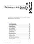
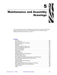
6(&7,210$,17(1$1&($1'$66(0%/<'5$:,1*6 DESCRIPTION . . . . . . . . . . . . . . . . . . . . . . . . . . . . . . . . . . . . . . . . . . . . . . . . . . . . . . . . . 5-1
LIST OF TABLES . . . . . . . . . . . . . . . . . . . . . . . . . . . . . . . . . . . . . . . . . . . . . . . . . . . . . . . 5-2
LIST OF FIGURES . . . . . . . . . . . . . . . . . . . . . . . . . . . . . . . . . . . . . . . . . . . . . . . . . . . . . . 5-3
6(&7,21237,21.,76 BACKING REWIND OPTION KIT (LINER REWIND) . . . . . . . . . . . . . . . . . . . . . . . . . . . . 6-1
Installation . . . . . . . . . . . . . . . . . . . . . . . . . . . . . . . . . . . . . . . . . . . . . . . . . . . . . . . . . . 6-2
Reconfigure the Printer for Peel Operation . . . . . . . . . . . . . . . . . . . . . . . . . . . . . . . . . 6-8
Adjusting the Platen Support Bracket . . . . . . . . . . . . . . . . . . . . . . . . . . . . . . . . . . . . . 6-8
MEDIA REWIND OPTION KIT . . . . . . . . . . . . . . . . . . . . . . . . . . . . . . . . . . . . . . . . . . . . . 6-9
Installation . . . . . . . . . . . . . . . . . . . . . . . . . . . . . . . . . . . . . . . . . . . . . . . . . . . . . . . . . 6-10
Reconfigure the Printer for Rewind Operation . . . . . . . . . . . . . . . . . . . . . . . . . . . . . . 6-14
Adjusting the Platen Support Bracket . . . . . . . . . . . . . . . . . . . . . . . . . . . . . . . . . . . . 6-15
CUTTER CATCH TRAY OPTION . . . . . . . . . . . . . . . . . . . . . . . . . . . . . . . . . . . . . . . . . . 6-15
INTERNAL FANFOLD SUPPLY BIN OPTION . . . . . . . . . . . . . . . . . . . . . . . . . . . . . . . . 6-16
INTERNAL ZEBRANET PRINTSERVER II OPTION . . . . . . . . . . . . . . . . . . . . . . . . . . . 6-17
EXTERNAL ZEBRANET PRINTSERVER II OPTION . . . . . . . . . . . . . . . . . . . . . . . . . . 6-20
COAX COMMUNICATIONS INTERFACE BOARD OPTION . . . . . . . . . . . . . . . . . . . . . 6-22
TWINAX COMMUNICATIONS INTERFACE BOARD OPTION . . . . . . . . . . . . . . . . . . . 6-26
CUTTER OPTION . . . . . . . . . . . . . . . . . . . . . . . . . . . . . . . . . . . . . . . . . . . . . . . . . . . . . . 6-29
32056L Rev. 2 12/4/01
105SL Maintenance Manual
Page v
TABLE OF CONTENTS
/,672)),*85(6
Figure 1-1. Default Fonts Examples .....................................................................................1-4
Figure 1-2. 105SL Printhead ................................................................................................1-7
Figure 1-3. Upper Media Sensor ..........................................................................................1-8
Figure 1-4. Lower Media Sensor and Bracket ......................................................................1-8
Figure 1-5. Take Label Sensor Pair ......................................................................................1-9
Figure 1-6. Ribbon Sensor, Guard Plate and Printhead ......................................................1-9
Figure 2-1. Front Panel .........................................................................................................2-1
Figure 2-2. AC Power Cord ..................................................................................................2-4
Figure 2-3. Rear Panel Showing Interface Connectors ........................................................2-5
Figure 2-4. Supplied Serial Interface Adapters ....................................................................2-6
Figure 2-5. Serial Data Connection ......................................................................................2-6
Figure 2-6. Serial Interface (Printers with DB-25 Connector) ...............................................2-7
Figure 2-7. Serial Interface (Printers with DB-9 Connector) .................................................2-8
Figure 2-8. RS-232 Signaling ...............................................................................................2-9
Figure 2-10. Parallel Data Connection ...............................................................................2-10
Figure 2-9. RS-422/RS-485 Signaling ................................................................................2-10
Figure 2-11. Coax Adapter Cable and Interface Hook-up ..................................................2-12
Figure 2-12. Twinax Adapter Cable and Interface Hook-up ...............................................2-12
Figure 2-13. Printer Media Side Parts ................................................................................2-13
Figure 2-14. Roll Media Loading Tear-Off Mode ................................................................2-14
Figure 2-15. Peel and Liner Rewind Loading .....................................................................2-15
Figure 2-16. Media Rewind w/o Cutter Option ...................................................................2-16
Figure 2-17. Cutter Mode Loading ......................................................................................2-17
Figure 2-18. Fanfold Media Loading ..................................................................................2-18
Figure 2-19. Aligning Spindle Segments ............................................................................2-19
Figure 2-20. Making a Ribbon Leader ................................................................................2-20
Figure 2-21. Ribbon Installation ..........................................................................................2-20
Figure 2-23. Ribbon Removal .............................................................................................2-21
Figure 2-22. Ribbon Hook Fit .............................................................................................2-21
Figure 2-24. Lower Media Sensor Location .......................................................................2-22
Figure 2-25. Upper Media Sensor Location .......................................................................2-23
Figure 2-26. Maximum Label Length ..................................................................................2-31
Figure 2-27. Sensor Profile Sample Label .........................................................................2-35
Figure 2-28. Diagnostics Sample Label .............................................................................2-39
Figure 2-29. Label Top Position .........................................................................................2-43
Figure 2-30. Left Position ...................................................................................................2-44
Figure 2-31. Installing PCMCIA Card .................................................................................2-48
Figure 3-1. CANCEL Key Test Sample Label ......................................................................3-4
Figure 3-2. PAUSE Key Test Sample Label .........................................................................3-5
Figure 3-4. Communications Diagnostics Self Test .............................................................3-6
Figure 3-3. FEED Key Self Test Sample Label ....................................................................3-6
Figure 3-5. PAUSE Key Loopback Test Sample Label ........................................................3-7
Figure 3-6. PAUSE Key Loopback Test Sample Label ........................................................3-8
Page vi
105SL Maintenance Manual
32056L Rev. 2 12/4/01
TABLE OF CONTENTS
Figure 3-7. Format 1 and 4 Test Sample Label ................................................................... 3-9
Figure 3-8. Format 2 and 5 Test Sample Label ................................................................... 3-9
Figure 3-9. Format 3 and 6 Test Sample Label ................................................................. 3-10
Figure 3-10. Format 7 and 11 Test Sample Label ............................................................. 3-10
Figure 3-11. Format 8 and 12 Test Sample Label ............................................................. 3-10
Figure 3-12. Format 9 and 13 Test Sample Label ............................................................. 3-11
Figure 3-13. Format 10 and 14 Test Sample Label ........................................................... 3-11
Figure 4-1. Cleaning a Typical Printhead ............................................................................. 4-6
Figure 4-2. Removal and Installation of Snap Plate ............................................................ 4-7
Figure 4-3. External Printer Components ............................................................................ 4-8
Figure 4-4. Interconnection Diagram for Printer Configurations 10500-0XXX-XXXX
and 10500-1XXX-XXXX ................................................................................................. 4-9
Figure 4-5. Interconnection Diagram for Printer Configurations 10500-2XXX-XXXX and
10500-3XXX-XXXX ...................................................................................................... 4-10
Figure 4-6. Power Switch and Power Cord Removal and Installation ............................... 4-11
Figure 4-7. Removing and Installing Data Cables ............................................................. 4-11
Figure 4-8. Removing and Installing the Electronics Cover ............................................... 4-12
Figure 4-9. DC Power Supply Removal and Installation .................................................... 4-14
Figure 4-10. AC Power Supply and Main Logic Board Removal/Installation .................... 4-15
Figure 4-11. AC/DC Power Supply Removal and Installation ........................................... 4-17
Figure 4-12. Main Logic Board Removal and Installation (Printer Configurations
10500-0XXX-XXXX and 10500-1XXX-XXXX) .............................................................. 4-19
Figure 4-13. Main Logic Board Removal and Installation (Printer Configurations
10500-2XXX-XXXX and 10500-3XXX-XXXX) .............................................................. 4-21
Figure 4-14. Main Drive Belt Adjustment ........................................................................... 4-23
Figure 4-15. Main Drive Belt .............................................................................................. 4-24
Figure 4-16. Rewind Drive Belt Tension Adjustment ......................................................... 4-25
Figure 4-17. Rewind Drive Belt Removal and Installation ................................................. 4-27
Figure 4-19. Printhead Resistance Value Label ................................................................ 4-28
Figure 4-18. Printhead Replacement ................................................................................. 4-28
Figure 4-20. Printhead Cleaning ........................................................................................ 4-29
Figure 4-21. Initial Toggle Setting ...................................................................................... 4-30
Figure 4-22. Printhead Adjustment .................................................................................... 4-32
Figure 4-23. Wear Plate Adjustment .................................................................................. 4-33
Figure 4-24. Upper Transmissive Media Sensor Position Adjustment .............................. 4-36
Figure 4-25. Lower Transmissive Media Sensor Position Adjustment .............................. 4-36
Figure 4-26. Take Label Sensor Location .......................................................................... 4-37
Figure 4-28. Peel-Off Lower Roller Alignment ................................................................... 4-38
Figure 4-27. Rewind Plate Assembly ................................................................................. 4-38
Figure 4-29. Spindle Tension Adjustments ........................................................................ 4-40
Figure 4-30. Media Rewind Spindle ................................................................................... 4-41
Figure 4-31. Ribbon Supply Spindle Maintenance ............................................................ 4-42
Figure 4-32. Ribbon Take-Up Spindle Maintenance .......................................................... 4-43
Figure 4-33. Platen Roller Removal ................................................................................... 4-45
Figure 4-34. Peel Roller Kit Parts ...................................................................................... 4-47
32056L Rev. 2 12/4/01
105SL Maintenance Manual
Page vii
TABLE OF CONTENTS
Figure 4-35. Membrane Switch and Front Panel ...............................................................4-49
Figure 4-36. Remove/Install Membrane Switch and Front Panel Assembly ......................4-50
Figure 4-37. LCD PCB Removal/Installation ......................................................................4-51
Figure 4-38. Media Supply Hanger Tabs ...........................................................................4-52
Figure 4-40. International Safety Organizations .................................................................4-53
Figure 4-39. Media Supply Hanger Installation ..................................................................4-53
Figure 4-41. AC Power Fuse Replacement 10500-0XXX-XXXX and 10500-1XXX-XXXX 4-54
Figure 4-42. AC Power Fuse Replacement 10500-2XXX-XXXX and 10500-3XXX-XXXX 4-55
Figure 4-43. Cutter Main Link and Slotted Removal and Installation .................................4-57
Figure 4-44. Cutter PCB Removal and Installation ............................................................4-59
Figure 4-45. Cutter PCB Connections ................................................................................4-60
Figure 4-46. Mechanical Assembly Positioning ..................................................................4-63
Figure 4-47. Cutter Motor Replacement .............................................................................4-65
Figure 4-48. Platen Pulley Replacement ............................................................................4-66
Figure 4-49. Upper Media Sensor Replacement ................................................................4-67
Figure 4-51. Upper Media Sensor and Bracket ..................................................................4-68
Figure 4-50. Linen Thread Placement ................................................................................4-68
Figure 4-52. Lower Media Sensor and Bracket ..................................................................4-69
Figure 4-53. Media Rewind Spindle Replacement .............................................................4-71
Figure 4-54. Ribbon Supply Spindle Kit Parts and Mounting Location ..............................4-72
Figure 4-55. Ribbon Take-up Spindle ................................................................................4-74
Figure 4-56. Rear Panel Fasteners ....................................................................................4-75
Figure 4-57. Rear Panel Wiring ..........................................................................................4-76
Figure 4-58. Ribbon Take-up Pulley Replacement ............................................................4-77
Figure 4-59. Media Take-up Pulley Replacement ..............................................................4-79
Figure 4-60. Peel Roller Pulley Replacement ....................................................................4-80
Figure 4-61. Pivot Bar, Handle and Toggle Parts ...............................................................4-81
Figure 4-62. Rewind Plate Replacement ............................................................................4-83
Figure 4-63. Printhead Replacement .................................................................................4-84
Figure 4-64. Guard Plate and Sensor ................................................................................4-85
Figure 4-65. Wire Tie Removal and Installation .................................................................4-85
Figure 4-66. Printhead Cleaning .........................................................................................4-86
Figure 4-67. Take-Label Sensors .......................................................................................4-87
Figure 4-68. Freeing Side Plate for Removal .....................................................................4-89
Figure 4-69. Side Plate Removal and Installation ..............................................................4-90
Figure 4-70. DC Stepper Motor Removal and Installation .................................................4-91
Figure 4-71. Black Mark Sensor Installation .......................................................................4-92
Figure 4-72. Media Cover Replacement ............................................................................4-93
Figure 5-1. Final Assembly (View 1) .....................................................................................5-5
Figure 5-2. Final Assembly (View 2) .....................................................................................5-7
Figure 5-3. Final Assembly (View 3 ) for Configuration Numbers 10500-0XXX-XXXX
and 10500-1XXX-XXXX ..................................................................................................5-9
Figure 5-4. Final Assembly (View 4) for Configuration Numbers 10500-2XXX-XXXX
and 10500-3XXX-XXXX ................................................................................................5-11
Figure 5-5. Printhead Support Assembly ...........................................................................5-13
Page viii
105SL Maintenance Manual
32056L Rev. 2 12/4/01
TABLE OF CONTENTS
Figure 5-6. Main and Lower Platen Rollers ....................................................................... 5-15
Figure 5-7. Media Supply Hanger ...................................................................................... 5-17
Figure 5-8. Ribbon Supply Spindle .................................................................................... 5-19
Figure 5-9. Ribbon Take-up Spindle and Pulley ................................................................ 5-21
Figure 5-10. Media Guide Assembly .................................................................................. 5-22
Figure 5-11. Front Panel and LCD Display ........................................................................ 5-23
Figure 5-12. Power Supplies .............................................................................................. 5-24
Figure 5-13. Pivot Bar Assembly ....................................................................................... 5-25
Figure 5-14. Backing Rewind Assembly ............................................................................ 5-27
Figure 5-15. Media Rewind Option .................................................................................... 5-29
Figure 5-16. Cutter Option (View 1) ................................................................................... 5-31
Figure 5-17. Cutter Option (View 2) ................................................................................... 5-32
Figure 5-18. Communication Options ................................................................................ 5-33
Figure 5-19. Fanfold Bin Option ......................................................................................... 5-34
Figure 6-1. Backing Rewind Option Kit ................................................................................ 6-2
Figure 6-2. Liner Rewind Assembly Installation ................................................................... 6-3
Figure 6-3. Take-Label Sensors .......................................................................................... 6-5
Figure 6-4. Sensor Connector Location (Printer Configurations 10500-0XXX-XXXX
and 10500-1XXX-XXXX) ................................................................................................ 6-6
Figure 6-5. Sensor Connector Location (Printer Configurations 10500-2XXX-XXXX
and 10500-3XXX-XXXX) ................................................................................................ 6-6
Figure 6-6. Initial Rewind Drive Belt Tensioning .................................................................. 6-7
Figure 6-7. Platen Support Bracket Adjustment .................................................................. 6-8
Figure 6-8. Media Rewind Option Kit ................................................................................. 6-10
Figure 6-9. Media Rewind Installation ................................................................................ 6-11
Figure 6-10. Rewind Plate Installation ............................................................................... 6-13
Figure 6-11. Cutter Catch Tray Installation ........................................................................ 6-16
Figure 6-12. Cutter Catch Tray Length and Width Adjustments ........................................ 6-17
Figure 6-13. Internal Fanfold Supply Bin Installation ......................................................... 6-18
Figure 6-14. Rear Panel ..................................................................................................... 6-19
Figure 6-15. Internal PrintServer ll Installation (Printer Configurations 10500-0XXX-XXXX and
10500-1XXX-XXXX) ..................................................................................................... 6-20
Figure 6-16. Internal PrintServer ll Installation (Printer Configurations 10500-2XXX-XXXX and
10500-3XXX-XXXX) ..................................................................................................... 6-21
Figure 6-17. External PrintServer ...................................................................................... 6-22
Figure 6-18. Coax Communications Interface Board Installation (Printer Configurations
10500-0XXX-XXXX and 10500-1XXX-XXXX) .............................................................. 6-23
Figure 6-19. Coax Communications Interface Board Installation (Printer Configurations
10500-2XXX-XXXX and 10500-3XXX-XXXX) .............................................................. 6-23
Figure 6-20. Coax Adapter Cable and Interface Hook up ................................................. 6-24
Figure 6-21. Twinax Interface Board Installation (Printer Configurations 10500-0XXX-XXXX
and 10500-1XXX-XXXX) .............................................................................................. 6-26
Figure 6-22. Twinax Interface Board Installation (Printer Configurations 10500-2XXX-XXXX
and 10500-3XXX-XXXX) .............................................................................................. 6-27
Figure 6-23. Twinax Connections ...................................................................................... 6-28
32056L Rev. 2 12/4/01
105SL Maintenance Manual
Page ix
TABLE OF CONTENTS
/,672)7$%/(6
Table 1-1. Font Matrices for 8 dot/mm (203 DPI) 105SL Printheads ........................... 1-3
Table 1-2. Font Matrices for 12 dot/mm (300 DPI) 105SL Printheads ......................... 1-4
Table 1-3. General Specifications ................................................................................ 1-5
Table 1-4. Printing Specifications ................................................................................. 1-5
Table 1-5. Ribbon Specifications .................................................................................. 1-5
Table 1-6. Media Specifications ................................................................................... 1-6
Table 1-7. Environmental Operating Ranges ............................................................... 1-7
Table 2-1. Front Panel Keys .........................................................................................2-2
Table 2-2. Front Panel Lights ....................................................................................... 2-3
Table 2-3. AC Power Cords .........................................................................................2-4
Table 2-4. Centronics® Parallel Cable ....................................................................... 2-11
Table 3-1. Format Sequence ........................................................................................ 3-7
Table 3-2. Troubleshooting ........................................................................................ 3-11
Table 4-1. Recommended Preventive Maintenance Schedule .................................... 4-4
Table 5-1. Final Assembly (View 1) .............................................................................. 5-4
Table 5-2. Final Assembly (View 2) .............................................................................. 5-6
Table 5-3. Final Assembly (View 3) for Configuration Numbers 10500-0XXX-XXXX
and 10500-1XXX-XXX ............................................................................................ 5-8
Table 5-4. Final Assembly (View 4) for Configuration Numbers 10500-2XXX-XXXX
and 10500-3XXX-XXXX ........................................................................................ 5-10
Table 5-5. Printhead Support Assembly ..................................................................... 5-12
Table 5-6. Main and Lower Platen Rollers ................................................................. 5-14
Table 5-7. Media Supply Hanger ................................................................................ 5-17
Table 5-8. Ribbon Supply Spindle .............................................................................. 5-18
Table 5-9. Ribbon Take-up Spindle and Pulley .......................................................... 5-20
Table 5-10. Media Guide Assembly ........................................................................... 5-22
Table 5-11. Front Panel and LCD Display .................................................................. 5-23
Table 5-12. AC and DC Power Supplies ....................................................................5-24
Table 5-13. Pivot Bar Assembly ................................................................................. 5-25
Table 5-14. Backing Rewind Assembly ...................................................................... 5-26
Table 5-15. Media Rewind Option .............................................................................. 5-28
Table 5-16. Cutter Option ........................................................................................... 5-30
Table 5-17. Communication Options .......................................................................... 5-33
Table 5-18. Fanfold Bin Option ..................................................................................5-34
Table 6-1. Backing Rewind Option Kit Inventory .......................................................... 6-1
Table 6-2. Media Rewind Option Kit ............................................................................. 6-9
Table 6-3. Coax Dip Switch Setting ............................................................................ 6-24
Table 6-4. Setting Printer Configuration for Coax ......................................................6-25
Table 6-6. Setting Printer Configuration for Twinax ................................................... 6-27
Table 6-5. Twinax Dip Switch Setting .........................................................................6-28
Table 6-6. Setting Printer Configuration for Twinax ................................................... 6-29
Page x
105SL Maintenance Manual
32056L Rev. 2 12/4/01
DESCRIPTION OF EQUIPMENT
SECTION 1
6(&7,21
'(6&5,37,212)(48,30(17
'(6&5,37,21
The Zebra 105SL printer is a versatile label and ticket printer designed to print high quality bar
codes, various sizes and styles of alphanumeric characters, and graphics in either the thermal
transfer or direct thermal mode.
The 105SL printer has the flexibility to meet a variety of applications. The Zebra Programming
Language II (ZPL II) allows the programmer to format the printed material. ZPL II is
transparent to protocol converters and allows the 105SL printer to be easily integrated with
most systems and host mainframes.
The printer identification label on the rear of the unit identifies the configuration of the printer.
The format of the Configuration Number is as follows:
10500-1XXX-XXXX
This manual covers the two major configurations of the 105SL. The significant differences
between configurations is denoted by the first digit of the second group of numbers. If that digit
is a zero (0) or one (1), the 105SL is equipped with a 25-pin serial interface connector, has a
black main frame, and has separate AC and DC power supplies. If that digit is a two (2) or
three (3), the 105SL is equipped with a 9-pin serial interface connector, has a silver main
frame, and has an integrated AC/DC power supply.
0(',$+$1'/,1*02'(6
Tear-off mode allows you to tear off each label, or a strip of labels.
In peel-off mode, backing material is peeled away from the label as it is printed. After this
label is removed from the printer, the next one is printed.
In cutter mode, the printer automatically cuts the label after a specified length of media or a
specified number of labels has been printed.
In rewind mode, the media and backing are rewound onto a core as the labels are printed.
35,17,1*0(7+2'6
There are two methods of printing: direct thermal and thermal transfer. The choice of printing
method can be made via the front panel controls and LCD or with the ZPL command ^MT.
Thermal Transfer method. In this method of printing, the ink is carried on special ribbon
material and transferred directly onto the paper media by the printhead.
NOTE:
For thermal transfer print mode, load ribbon before performing
calibration.
32056L Rev. 2 12/4/01
105SL Maintenance Manual
Page 1-1
SECTION 1
DESCRIPTION OF EQUIPMENT
In thermal transfer printing, the printhead is in contact with a ribbon that releases ink above a
certain threshold temperature. The image is formed when heat from the printhead is
transferred to the ribbon, releasing ink directly to the substrate (media) to produce the printed
image. The resulting image is stable and is not affected by exposure to UV or sunlight as with
direct thermal substrate.
Direct Thermal method. Ribbon is not used in this method. A substrate, typically paper, is
coated with a chemical that changes to a dark color upon exposure to heat over a period of
time.
NOTE:
Do NOT load ribbon if the printer is to be used in the direct thermal mode.
The image is not formed by burning, but by the chemical reaction in the coating brought on by
the heat from the printhead. Small electrical heaters in the thermal printhead are controlled by
the logic in the printer. The heaters are in the form of rectangular dots or bars and, when
activated, create an image in the substrate that closely matches the size and shape of the
heating element.
6&23(
This section of the manual is intended to supplement the printer’s User’s Guide by providing
additional information to aid the service technician in troubleshooting and maintaining the
printer.
237,216
Printhead 300 dpi (12 dots/mm)
Full width rotary knife cutter
Media rewind spindle
Label peel and liner rewind
Internal fanfold media supply bin
Reflective (black mark) media sensor
ZebraNet Printer Server II
Twinax or Coax Interface option
PCMCIA Flash memory slot
BAR-ONE Windows-based WYSIWYG on-screen label design
and print application software
=(%5$352*5$00,1*/$1*8$*(=3/$1'=3/,,
Communicates in printable ASCII characters
Compatible with mainframe, mini-computer and PC
hosts
Downloadable graphics, scalable and bitmap fonts,
label templates and formats
Adjustable print cache
Data compression
Automatic memory allocation for format while printing
Automatic serialization of fields
Format inversion
Mirror image printing
Four-position field rotation (0°, 90°, 180°, 270°)
Slew command
Programmable label quantity with print, pause, and
cut control
Status message to host upon request
ZBI™ (Zebra Basic Interpreter)
Page 1-2
105SL Maintenance Manual
32056L Rev. 2 12/4/01
DESCRIPTION OF EQUIPMENT
SECTION 1
%$5&2'(6<0%2/2*,(6
Bar code ratios — 2:1, 7:3, 5:2, & 3:1
2 dimensional bar codes:
• CODABLOCK
• PDF-417
• Micro PDF-417
• Code 49
• Data Matrix
• Maxi Code
• QR-Code
• Code 128 (with subsets A, B, and C and
UCC case C codes)
Linear bar codes:
• Code 11
• Code 39
• Code 93
• ISBT-128
• UPC-A, UPC Extensions
• UPC-E
• EAN-8
• EAN-13
• UPC and EAN 2 or 5 digit expressions
• Plessey
• Postnet
• Standard 2 of 5
• Industrial 2 of 5
• Interleaved 2 of 5
• LOGMARS
• MSI
• Codabar
67$1'$5'35,17(5)2176
Bitmap fonts A, B, C, D, E, F, G, H, and GS are expandable up to 10 times, height and width
independently. However, fonts E and H (OCR-A and OCR-B) are not considered “in-spec”
when expanded.
The smooth scalable font 0 (CG Triumvirate™ Bold Condensed) is expandable on a dot-bydot basis, height and width independent, while maintaining smooth edges. Maximum
character size depends on available memory.
IBM Code Page 850 international character sets are available in the fonts A, B, C, D, E, F, G,
and 0 through software control.
Table 1-1. Font Matrices for 8 dot/mm (203 DPI) 105SL Printheads
Character Size
Font
Matrix
Type*
Height
Width
Intercharacter
gap
A
9
5
1
B
11
7
C,D
18
E
Inches
Millimeters
Height
Width
Char./
Inch
Height
Width
Char./
mm
U-L-D
0.044
0.030
33.9
1.13
0.75
1.33
2
U
0.054
0.044
22.6
1.38
1.13
0.89
10
2
U-L-D
0.089
0.059
16.9
2.25
1.50
0.67
28
15
5
OCR-B
0.138
0.098
10.2
3.50
2.50
0.40
F
26
13
3
U-L-D
0.128
0.079
12.7
3.25
2.00
0.50
G
60
40
8
U-L-D
0.295
0.236
4.2
7.50
6.00
0.17
H
21
13
6
OCR-A
0.103
0.094
10.7
2.63
2.38
0.42
GS
24
24
0
SYMBOL
0.118
0.118
8.5
3.00
3.00
0.33
0
variable
U-L-D
variable
* U = Uppercase, L = Lowercase, D = Descenders
32056L Rev. 2 12/4/01
105SL Maintenance Manual
Page 1-3
SECTION 1
DESCRIPTION OF EQUIPMENT
Table 1-2. Font Matrices for 12 dot/mm (300 DPI) 105SL Printheads
Character Size
Font
Matrix
Type*
Height
Width
Intercharacter
gap
A
9
5
1
B
11
7
C,D
18
E
F
G
Inches
Millimeters
Height
Width
Char./
Inch
Height
Width
Char./
mm
U-L-D
0.030
0.020
50.0
0.76
0.51
1.97
2
U
0.037
0.030
33.3
0.93
0.76
1.31
10
2
U-L-D
0.060
0.040
25.0
1.53
1.02
0.98
41
20
6
OCR-B
0.137
0.087
11.5
3.47
2.20
0.45
26
13
3
U-L-D
0.087
0.053
18.7
2.20
1.36
0.74
60
40
8
U-L-D
0.200
0.160
6.2
5.08
4.07
0.25
H
30
19
9
OCR-A
0.100
0.093
10.7
2.54
2.37
0.42
GS
24
24
0
SYMBOL
0.080
0.080
12.5
2.03
2.03
0.49
0
variable
U-L-D
variable
* U = Uppercase, L = Lowercase, D = Descenders
Figure 1-1. Default Fonts Examples
Page 1-4
105SL Maintenance Manual
32056L Rev. 2 12/4/01
DESCRIPTION OF EQUIPMENT
SECTION 1
63(&,),&$7,216
The following tables provide specifications for the printer, media, and ribbon. Using media or ribbon not
designed for the printer can cause unsatisfactory results.
Table 1-3. General Specifications
Printer Physical Characteristics
105SL (203 dpi)
105SL (300 dpi)
Height
15.5″
394 mm
15.5″
394 mm
Width
11.2″
284 mm
11.2″
284 mm
Depth
18.9″
480 mm
18.9″
480 mm
Weight (without options)
55 lbs.
25 kg
55 lbs.
25 kg
Table 1-4. Printing Specifications
Printing Specifications
105SL (203 dpi)
105SL (300 dpi)
203 dots/inch(8 dots/mm)
300 dots/inch (12 dots/mm)
Dot size (width x length)
0.0049″ x 0.0049″
(0.125 x 0.125 mm)
0.0033″ x 0.0039″
(0.084 mm x 0.100 mm)
First dot location measured from inside
media edge
0.10″ ±0.035″
(2.5 mm ±0.89 mm)
0.10″ ±0.035″
(2.5 mm ±0.89 mm)
4.09″ (104 mm)
4.09″ (104 mm)
Resolution
Maximum print width
Print Length
(maximum)
Bar code
modulus
(“X”)
dimension
Non-continuous
printing
Standard
memory
39″ (991 mm)
39″ (991 mm)
Continuous
printing
Standard
memory
106″ (2692 mm)
65″ (1651 mm)
Ladder (rotated) orientation
4.9 mil to 49 mil
3.9 mil to 39 mil
Picket fence (non-rotated)
orientation
4.9 mil to 49 mil
3.3 mil to 33 mil
Yes
Yes
Thin film printhead with Element Energy
Equalizer® (E3)
Table 1-5. Ribbon Specifications
Maximum
4.5″
114 mm
Minimum
0.79″
20 mm
2:1 media to ribbon roll ratio
984’
300 m
3:1 media to ribbon roll ratio
1476’
450 m
Inner diameter of core
1.0″
25.4 mm
Outside diameter of full ribbon roll
3.2″
81.3 mm
Ribbon width: To protect the printhead from wear, Zebra
recommends using ribbon at least as wide as the media
you are using.
Standard lengths
Roll size
32056L Rev. 2 12/4/01
105SL Maintenance Manual
Page 1-5
SECTION 1
DESCRIPTION OF EQUIPMENT
Table 1-6. Media Specifications
Minimum label length*
Total media width (label + liner, if any)
Total thickness (includes liner, if any)
Tear-off
0.7″ (18 mm)
Peel-off
0.5″ (13 mm)
Cutter
1.5″ (38 mm)
Rewind
0.25″ (6 mm)
Minimum
0.79″ (20 mm)
Maximum
4.52 mm (115 mm)
Minimum
0.003″ (0.076 mm)
Maximum
0.012″ (0.305 mm)
3″ (76 mm)
Roll media core inside diameter
8.0″ (203 mm)
Maximum roll diameter
Inter-label gap
Minimum
0.079″ (2 mm)
Preferred
0.118″ (3 mm)
Maximum
0.157″ (4 mm)
Maximum internal fanfold media pack size (label + liner) L x W x H
8.0″ x 4.5″ x 4.5″
(203 mm x 114 mm x 114 mm)
Ticket/tag sensing notch L x W
0.12″ x 0.25″ (3 mm) x (6 mm)
0.125″ (3 mm)
Ticket/tag sensing hole diameter
Effective leading edge registration accuracy*
Mark length (measuring
parallel to label/tag edge)
Additional
specifications for
black mark sensing
Mark width (measuring to
perpendicular label/tag edge)
Vertical
0.050″ (±1.3 mm)
Horizontal
0.050″ (±1.3 mm)
Minimum
0.12″ (3 mm)
Maximum
0.43″ (11 mm)
Minimum
0.43″ (11 mm)
Maximum
Full media width
Mark location
Marks must be located within 0.040″
(1 mm) of the inside media edge.
Mark density
>1.0 Optical Density Unit (ODU)
Maximum density of the back of the media on
which the black mark is printed
0.5 ODU
* Media registration and minimum label length are affected by media type and width, ribbon type, print speed,
and printer mode of operation. Performance improves as these factors are optimized. Zebra recommends
always qualifying any application with thorough testing.
Page 1-6
105SL Maintenance Manual
32056L Rev. 2 12/4/01
DESCRIPTION OF EQUIPMENT
SECTION 1
Table 1-7. Environmental Operating Ranges
Thermal Transfer:
+40°F to +104°F (+5°C to +40°C)
Temperature
Direct Thermal:
+40°F to +104°F (+5°C to +40°C)
Storage
-40°F to +140°F (-40°C to +60°C)
Non-condensing
relative humidity
Operating
20% to 85%
Storage
5% to 85%
(/(&75,&$/5(48,5(0(176
•
•
•
Universal power supply with power factor correction 90-264VAC, 48-62Hz.
Power Consumption
Idle = 19 W
Printing = 180 W (printing pause test label at speed A)
Agency approvals: UL 1950, CISPR 22 (class B), IEC 950, 801-2, -3, and -4 standards,
CSA 950,Canadian Doc. (class A), FCC (class A), CE compliance
29(59,(:2))81&7,2162)0$-25$66(0%/,(6
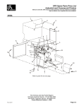
3ULQW0HFKDQLVPDQG3ULQWKHDG
The print mechanism (see Figure 1-2) carries the printhead and has mechanical devices that
allow the printhead to be adjusted for optimum print quality. The printhead is an electrical part
that causes the printing to be done. The Zebra 105SL printer features a thin film printhead with
E3® Element Energy Control.
Do Not Loosen
These Screws !!
Printhead
Mechanism
Assembly
Printhead
Mounting
Screw
Power Cable
Locking Tab
Printhead
Data
Connector
Printhead
Power
Connector
Printhead
Alignment
Slots
Printhead
Resistance
Label
Figure 1-2. 105SL Printhead
0HGLDDQG5LEERQ6HQVRUV
There are several sensors mounted in the 105SL printer that monitor the presence of ribbon and
media and signal the processor. The media sensors are shown in Figure 1-3 and Figure 1-4.
32056L Rev. 2 12/4/01
105SL Maintenance Manual
Page 1-7
SECTION 1
DESCRIPTION OF EQUIPMENT
7UDQVPLVVLYH0HGLD6HQVRUV
The upper and lower transmissive media sensor pair monitor the presence of media at the
printhead. The bottom sensor is an infrared transmitter and the upper sensor is the receiver.
Adjustment Screw
Attaching Screws
Figure 1-3. Upper Media Sensor
Lower
Media Sensor
Grommet
Figure 1-4. Lower Media Sensor and Bracket
When the printer is using continuous media, the sensor pair merely confirm that there is
media in the machine. If the media broke or was exhausted, the sensor would send a
message to the processor and the processor would pause the machine and send a message
to the LCD.
When the printer is using non continuous media, the sensors are used to signal the
processor that the interval has been detected and the printing stops. The printer stops based
Page 1-8
105SL Maintenance Manual
32056L Rev. 2 12/4/01
DESCRIPTION OF EQUIPMENT
SECTION 1
on the information from the transmissive media sensor pair but starts based on information
from another pair of media sensors, the take label or label available sensor pair.
7DNH/DEHO6HQVRUV
See Figure 1-5. This pair of sensors detects the absence of a label printed on non-continuous
media in the peel off mode. When the label is removed, the sensor pair signals the processor
and the processor starts printing the next label.
Label
Available
Sensors
Figure 1-5. Take Label Sensor Pair
5LEERQ6HQVRU
See Figure 1-6. This sensor detects the absence of ribbon and sends a “ribbon out” message
to the processor. The processor pauses the printing until more ribbon is loaded.
Printhead Assembly
Allen Screw
Pivot Bar
Flat Washer
Washer
Split Grommet
Ribbon Sensor
(See Note)
Guard Plate
Allen Screws
Note:
Position Ribbon Sensor Tab Not
To Be Flush With Top Edge of Pivot Bar.
Gap 0.010 Min./0.030 Max. Below Top Edge.
Figure 1-6. Ribbon Sensor, Guard Plate and Printhead
32056L Rev. 2 12/4/01
105SL Maintenance Manual
Page 1-9
SECTION 1
DESCRIPTION OF EQUIPMENT
6SLQGOHV
The105SL printer uses 4 different spindles. Refer to Section 5 for exploded view drawings of
these spindles.
RIBBON SUPPLY SPINDLE. Supports and dispenses ribbon to and through the printhead.
Maintains a little back pressure on the ribbon to keep it from pulling off the spindle too fast.
RIBBON TAKE-UP SPINDLE. Helps pull the ribbon through the printer. Maintains the correct
ribbon tension for highest quality printing. Prevents ribbon from unwinding.
MEDIA REWIND SPINDLE. Winds up printed media and liner (used in rewind mode only).
LINER REWIND SPINDLE. Winds up used liner (used in peel-off mode only).
Page 1-10
105SL Maintenance Manual
32056L Rev. 2 12/4/01
OPERATION OVERVIEW
SECTION 2
6(&7,21
23(5$7,2129(59,(:
23(5$725&21752/6
This section discusses the functions of the various controls and indicators on the Zebra
105SL. Become familiar with each of the controls before servicing the printer.
)URQW3DQHO'LVSOD\
The Front Panel Display, as shown in Figure 2-1, communicates operational and
programming modes and parameters.
35(9,286
1(;76$9(
6(783(;,7
32:(5
7$.(/$%(/
(5525
&+(&.5,%%21
3$3(5287
3$86(
)(('
'$7$
&$1&(/
Figure 2-1. Front Panel
32056L Rev. 2 12/4/01
105SL Maintenance Manual
Page 2-1
SECTION 2
OPERATION OVERVIEW
)URQW3DQHO.H\V
For an explanation of the front panel controls, refer to the following table and to Figure 2-1.
Table 2-1. Front Panel Keys
Key
Function
Starts and stops the printing process.
•
If the printer is not printing: no printing can occur.
•
If the printer is printing: printing stops once the current label is complete.
Press to remove error messages from the display.
NOTE: Pause mode can also be activated via ZPL II (~PP, ^PP).
Forces the printer to feed one blank label each time the key is pressed.
•
Printer not printing: one blank label immediately feeds.
•
Printing: one blank label feeds after the current batch of labels is complete.
When in the pause mode, this key cancels print jobs.
•
Print job in queue: press once for each print job to be deleted.
•
Press and hold for several seconds to cancel all print jobs in the printer’s memory. The
DATA light turns off.
NOTE: The keys below are used only when configuring the printer. Specific uses of these keys are explained
in the Configuration section of the User's Guide, PN 32051L.
•
Scrolls back to the previous menu item.
•
Press and hold to quickly go backward through parameter sets.
•
Scrolls forward to the next menu item. Saves any changes you’ve made in the
configuration and calibration sequence.
•
Press and hold to quickly advance through parameter sets.
Enters and exits the configuration mode.
These keys change the parameter values. They are used in different ways depending on the
parameter displayed. Common uses are: to increase/decrease a value, answer “yes” or “no,”
indicate “on” or “off,” scroll through several choices, input the password, or set up the printer
for a firmware download.
Page 2-2
105SL Maintenance Manual
32056L Rev. 2 12/4/01
OPERATION OVERVIEW
SECTION 2
)URQW3DQHO,QGLFDWRUV
For an explanation of the front panel indicators, refer to the following table and to Figure 2-1.
NOTE:
If two operating conditions occur simultaneously (for example, one that
causes a light to be on constantly and one that causes the same light to
flash), the light flashes.
Table 2-2. Front Panel Lights
Light
Status
Power—green
Off
Indication
The printer is off or power is not applied.
The printer is on.
On
Take Label—green
Off
Flashing
Error—yellow
Off
Normal operation.
NOTE: Peel-off mode only. The label is available. Printing is paused
until the label is removed.
Normal operation — no printer errors.
A printer error exists. Check the display screen for more information.
Flashing
Check Ribbon—yellow
Off
On
Paper Out—yellow
Off
On
Off
On
Normal operation — ribbon, if used, is properly loaded.
The front panel displays a warning message.
If the printer is in direct thermal mode: Ribbon is loaded, but the printer
continues printing.
If the printer is in thermal transfer mode: No ribbon is loaded. The printer
is paused and the PAUSE light is on.
Normal operation — media is properly loaded.
No media is under the media sensor. Printing is paused, the display
shows an error message, and the PAUSE light is on.
Normal operation.
The printer has stopped all printing operations. Either the PAUSE key was
pressed, a pause command was included in the label format, or a printer
error was detected. Refer to the display screen for more information.
3$86(
with yellow light
Off
'$7$
When in the pause mode, this key cancels print jobs.
On
&$1&(/
Flashing
with green data light
32056L Rev. 2 12/4/01
Normal operation.
Data processing or printing is taking place.
•
Print job in queue: press once for each print job to be deleted.
Press and hold for several seconds to cancel all print jobs in the printer’s
memory. The green DATA light turns off.
The printer is receiving data from or sending status information to the host
computer. Flashing slows when the printer cannot accept more data, but
returns to normal once data is again being received.
105SL Maintenance Manual
Page 2-3
SECTION 2
OPERATION OVERVIEW
32:(5&25'
(OHFWULFDO5HTXLUHPHQWV
•
•
•
Universal power supply with power factor correction 90–264 VAC, 48–62 Hz.
Power Consumption
Idle = 19 W
Printing = 180 W (printing pause test label at speed A)
Agency approvals: UL 1950, CISPR 22 (class B), IEC 950, 801-2, -3, and -4 standards,
CSA 950, Canadian Doc. (class A), FCC (class A), CE compliance
&DEOH5HTXLUHPHQWV
The AC power cord has a three-prong female connector on one end. This connector must be
plugged into the mating connector at the rear of the printer.
9$&$SSOLFDWLRQV
A standard US-style, three-prong grounded male plug is attached to the other end of the AC
power cord. This connector must be plugged into a nearby electrical outlet.
9$&$SSOLFDWLRQV
An AC power cord may or may not be included with the printer. For those locations that cannot
use either of the three power cords listed below, a proper grounded AC power cord must be
obtained and installed by the user. See Figure 2-2. The cable must then be plugged into a
nearby electrical outlet.
Table 2-3. AC Power Cords
Part Number
44693
44629
44637
46639
AC Power Cable Description
120 VAC Detachable Power Cord w/NEMA 5-15 plug for US
230 VAC Detachable Power Cord w/CEE7-7 “SCHUKO” plug for Europe
230 VAC Detachable power Cord w/BS 1363 plug for UK
240 VAC Detachable power Cord w/SAA 3112-1993 plug for Australia
CEE 22
TYPE 5
CONNECTOR
ATTACHMENT
PLUG CAP FOR
YOUR COUNTRY
3 CONDUCTOR HAR
CONTACT
VIEW
NEUTRAL
EARTH
LIVE
Figure 2-2. AC Power Cord
Page 2-4
105SL Maintenance Manual
32056L Rev. 2 12/4/01
OPERATION OVERVIEW
SECTION 2
,17(5)$&(&211(&7,216
NOTE:
Depending on the Configuration Number on the printer identification
plate, the 105SL is equipped either with a DB-25 or a DB-9 serial
connector. If the printer has a DB-9 connector, a 9-pin to 25-pin adapter
and an RS-422/RS-485 adapter are available.
The printer is equipped with a parallel interface connector and a serial interface connector, as
shown in Figure 2-3. The interface cable is not supplied with the printer.
Parallel Interface
Connector
Serial Interface
Connector
(See Note)
AC Power
On/Off Switch
Note:
Depending on Configuration,
the Serial Interface may be a
DB-25 or a DB-9 connector.
AC Power
Cable Connection
Figure 2-3. Rear Panel Showing Interface Connectors
6HULDO'DWD&RPPXQLFDWLRQ,QWHUIDFH2YHUYLHZ
The Zebra 105SL has a single data terminal equipment (DTE) port. Depending on
configuration, a 25-pin or a 9-pin serial interface connector is mounted at the rear of the
printer. The 25-pin connector supports RS-232, RS-422 and RS-485 serial data
communications. The 9-pin connector supports RS-232 and requires an adapter (Zebra
part # 33130) to support RS-422 and RS-485 serial data communications. In order to connect
the DB-9 interface to a DB-25 connector, an adapter (Zebra part # 33138) is required. A
generic adapter may be used, but the 5 VDC signal source would not be passed through.
Figure 2-4 illustrates the DB-9 to DB-25 adapter and the cable wiring for interconnecting to the
RS-422 and RS-485 adapter.
Baud rate, parity, data length, stop bits, and XON/XOFF or DTR control protocols are front
panel selectable. The connector provides the data and control necessary to communicate
through all three signaling methods. The method used is specific to the application of the
printer. Refer to Figure 2-5 for serial data connection using a null modem cable.
32056L Rev. 2 12/4/01
105SL Maintenance Manual
Page 2-5
SECTION 2
OPERATION OVERVIEW
RS-422/RS-485 Adapter
DB-9 to DB-25 Adapter
Female DB25 Connector on
RS-422/RS-485 Adapter
Female DB-25 Adapter
Connector
(plugs into cable)
Male DB-9 Adapter
Connector
(plugs into printer)
2
RXD
FG
1
3
TXD
TXD
2
4
DTR
RXD
3
Frame ground
9
Signal ground ref.
5
SG
RTS
4
Data input B(-)
6
DSR
CTS
5
6
7
RTS
DSR
Data output B(-)
SG
CTS
7
8
9
+5VDC
SIGNAL
+5VDC
SIGNAL
DTR
1
+5VDC 725 mA source
11
13
14
Data input A(+)
16
9
Data output A(+)
19
20
NOTE: Pin 1 of DB9 connector is unused and unterminated.
NOTE: Pins 2-8, 10, 12, 15, 17-18, 20-25 are unused and unterminated.
Figure 2-4. Supplied Serial Interface Adapters
Printers with a DB-9 Serial Connector
Printers with a DB-25 Serial Connector
Printer
Computer
DB-25
Serial
Interface
Connector
Computer
DB-9
Serial
Interface
Connector
25
Null
Modem
Cable
Printer
Male
9
Null
Modem
Cable
25
Male
25
Male
25
Male
9
9
Null modem adapter
(if using a standard
modem cable)
Female
9
Null modem adapter
(if using a standard
modem cable)
50 maximum
Female
50 maximum
Figure 2-5. Serial Data Connection
For all RS-232 data and control input and output signals, the Zebra 105SL follows both the
Electronic Industries Association’s (EIA) RS-232 and the Consultative Committee for
International Telegraph and Telephone (CCITT) V.24 specifications.
'DWD&DEOH5HTXLUHPHQWV
Data cables must be fully shielded and fitted with metal or metallized connector shells.
Shielded cables and connectors are required to prevent radiation and reception of electrical
noise.
Page 2-6
105SL Maintenance Manual
32056L Rev. 2 12/4/01
OPERATION OVERVIEW
•
•
•
SECTION 2
Keep data cables as short as possible.
Do not bundle the data cables tightly with the power cords.
Do not tie the data cables to power wire conduits.
NOTE:
Zebra printers comply with FCC “Rules and Regulations”, part 15, Subpart
J, for Class A equipment, using fully shielded 6 foot long data cables. Use
of longer cables or unshielded cables may increase radiated emissions
above the Class A limits. RS-422 and RS-485 applications should use
twisted shielded pairs as recommended in the Appendix of the TIA/ETA-485
Specification.
&RPPXQLFDWLRQ%XIIHU
The 105SL printer has a communication buffer that stores the incoming data until that
information can be acted upon (imaged). Communication handshaking (DTR/DSR control
signals or XON/XOFF control codes) is used to control when the host can send data to the
printer.
As data is received by the 105SL printer, the processor monitors the number of characters in
the buffer. If the buffer is filled beyond its limit, the printer turns DTR to the OFF condition
(negative voltage) or transmits an XOFF (DC-3) control character to the host. When the buffer
empties below this limit, the 105SL turns DTR to the ON condition (positive voltage) or
transmits an XON (DC-1) control character to the host.
6WDQGDUG6HULDO&RPPXQLFDWLRQ&RQQHFWRU
The DTE port is a DB-25S or a DB-9S connector located at the rear of the printer. It provides
connection to a host via RS-232, RS-422 or RS-485 signaling. Refer to Figure 2-6 for the
DB-25 serial interface or to Figure 2-7 for the DB-9 serial interface wiring diagram.
RS-232 connector (DTE)
rear panel DB-25S
RS-422/RS-485 connector
rear panel DB-25S
+5 V
+5 V
1
FG (frame ground)
2
TXD (transmit data) output
3
RXD (receive data) input
4
RTS (request to send) output
6
DSR (data set ready) input
7
SG (signal ground)
F1
9
+5 VDC source
1 Amp
20
DTR (data terminal ready) output
F1
9
+5 VDC source
14
Data output B(-)
19
Data output A(+)
13
Data input B(-)
16
Data input A(+)
11
Signal ground reference
1
Frame ground
1 Amp
+5 V
10k
20k
10k
100
Figure 2-6. Serial Interface (Printers with DB-25 Connector)
32056L Rev. 2 12/4/01
105SL Maintenance Manual
Page 2-7
SECTION 2
OPERATION OVERVIEW
The pin outs and signal descriptions for the DB-25 DTE port are as follows:
Pin 1—FG (Frame ground) for cable shield.
Pin 2—TXD (RS-232 Transmit Data): Output from printer
Pin 3—RXD (RS-232 Receive Data): Input to printer
Pin 4—RTS (RS-232 Request to Send): Output from printer
Pin 6—DSR (RS-232 Data Set Ready): Input to printer
Pin 7—SG (Signal ground) for RS-232
Pin 9—+5VDC source (1 Amp maximum)
Pin 11—SGR (Signal ground reference) RS-422/RS-485
Pin 13—Data input B(–) RS-422/RS-485
Pin 14—Data output B(–) RS-422/RS-485
Pin 16—Data input A(+) RS-422/RS-485
Pin 19—Data output A(+) RS-422/RS-485
Pin 20—DTR (RS-232 Data Terminal Ready): Output from printer
NOTE:
Pins 5, 8, 10, 12, 15, 17-18 and 21-25 are not used and are not terminated.
RS-232 connector (DTE)
rear panel DB-9S
RS-422/RS-485
(Adapter Zebra part # 33138)
+5 V
+5 VDC
2
RXD (receive data) input
3
TXD (transmit data) output
4
DTR (data terminal ready) output
5
SG (signal ground)
6
DSR (data set ready) input
7
F1
9
+5 VDC source
14
Data output B(-)
19
Data output A(+)
13
Data input B(-)
RTS (request to send) output
16
Data input A(+)
8
CTS (clear to sent) input
11
Signal ground reference
9
+5 VDC source
1
Frame ground
725 mA
+5 V
1 k
Figure 2-7. Serial Interface (Printers with DB-9 Connector)
The pin outs and signal descriptions for the DB-9 DTE port are as follows:
Pin 1—Not used and not terminated
Pin 2—RXD (RS-232 Receive Data): Input to printer
Pin 3—TXD (RS-232 Transmit Data): Output from printer
Pin 4—DTR (RS-232 Data Terminal Ready): Output from printer
Pin 5—SG (Signal Ground)
Pin 6—DSR (RS-232 Data Set Ready): Input to printer
Pin 7—RTS (RS-232 Request To Send): Output from printer
Pin 8—CTS (RS-232 Clear To Send): Input to printer
Pin 9—+5 VDC signal
Page 2-8
105SL Maintenance Manual
32056L Rev. 2 12/4/01
OPERATION OVERVIEW
NOTE:
SECTION 2
Pin 9 is also available as a +5 VDC power source at 750 mA. To enable this
capability, a jumper needs to be installed between pins 2 and 3 at JP1 on
the Main Logic Board.
The pin outs and signal descriptions for the RS-422/RS-485 adapter are as follows:
Pin 1—FG (Frame ground) for cable shield.
Pin 9—+5VDC source (1 Amp maximum)
Pin 11—SGR (Signal ground reference) RS-422/RS-485
Pin 13—Data input B(–) RS-422/RS-485
Pin 14—Data output B(–) RS-422/RS-485
Pin 16—Data input A(+) RS-422/RS-485
Pin 19—Data output A(+) RS-422/RS-485
Pins 2–8, 10, 12, 15, 17-18 and 20-25 are not used and are not terminated.
6HULDO&RPPXQLFDWLRQ6LJQDO/HYHOV
Refer to Figure 2-8. RS-232 data signals are defined as either “Mark” or “Space”, while control
signals are ON (Active-Positive Voltage) or OFF (Inactive-Negative Voltage). Although the
permitted voltage levels can range from ±3 VDC to ±25 VDC, the levels for the 105SL printer
are as follows:
RS-232 Transmit and Receive Data
Mark or OFF = –7 to –10 VDC
Space or ON = +7 to +10 VDC
Start
Bit
Parity
Bit
Data Bits
+Space
0 Vdc
1
- Mark
(idle)
2
3
4
5
6
7
Logic 1
Logic 0
(idle)
Stop
Bit
Figure 2-8. RS-232 Signaling
Refer to Figure 2-9. RS-422 and RS-485 data signals are also either Mark or Space. The
voltage levels are +5 VDC and 0 VDC when monitored from a specified reference point. The
levels for the 105SL printer when referenced to signal ground are:
RS-422 and RS-485 Transmit and Receive Data
Mark Output/Input A = +5V and Output/Input B = 0V
Space Output/Input A = 0V and Output/Input B = +5V
32056L Rev. 2 12/4/01
105SL Maintenance Manual
Page 2-9
SECTION 2
OPERATION OVERVIEW
Logic 0
Stop
Bit
Logic 1
Mark
(Idle)
(+5 VDC)
(Idle)
1
(0 VDC)
Space
2
3
Start
Bit
4
5
6
Data Bits
7
Parity
Bit
Figure 2-9. RS-422/RS-485 Signaling
&RPPXQLFDWLRQ&RGH
The 105SL printer sends and receives ASCII (American Standard Code for Information
Interchange) characters in one of two formats, Serial Data or Parallel Data.
NOTE:
When using the serial data format, the baud rate, number of data and stop
bits per character, and parity are selectable. Parity only applies to data
transmitted by the 105SL printer. For received data, the parity bit is
ignored.
3DUDOOHO'DWD&RPPXQLFDWLRQV,QWHUIDFH2YHUYLHZ
A standard 36-pin parallel connector is available at the rear of the printer for connection to the
data source. Under normal circumstances, data sent from the printer to the host in response to
a “Printer Status Request” command is sent through the RS-232 serial port. However, if the
host has a properly configured IEEE-1284 parallel port that is recognized by the printer, status
information is returned through the parallel port. Port selection for status information is
determined each time the printer is turned on. See Figure 2-10.
Parallel Interface
Connector
Printer
Computer
36-pin
male
PC
25-pin
female
25-pin
male
Centronics Parallel
Cable (IEEE 1284)
6 maximum
Figure 2-10. Parallel Data Connection
Page 2-10
105SL Maintenance Manual
32056L Rev. 2 12/4/01
OPERATION OVERVIEW
SECTION 2
3DUDOOHO3RUW&RQQHFWRU
The following table shows the pin configuration and function of a standard PC-to-Printer
Centronics Parallel cable.
Table 2-4. Centronics® Parallel Cable
NOTE:
36-pin Connector
Description
1
nStrobe/HostClk
2–9
Data Bits 1–8
10
nACK/PtrClk
11
Busy/PtrBusy
12
PError/ACKDataReq
13
Select/Xflag
14
nAutoFd/HostBusy
15
Not Used
16 & 17
Ground
18
+5V @ 1A
19–30
Ground
31
ninit
32
nFault/NDataAvail
33 & 34
Not Used
35
+5V through a 4.7 K Ohm Resistor
36
NSelectIn/1284 active
Optional Ethernet Networking Communications via ZebraNet are available
via PrintServer II. Refer to the ZebraNet Networking: PrintServer II
Operator’s Guide, Zebra part # 45537L when using this communications
option.
2SWLRQDO,QWHUIDFH%RDUGV
For information about the IBM plug-compatible Twinax Interface, the IBM plug-compatible
Coax Interface and the RS-485 network interface, refer to the instructions that accompany the
interface option kits in Section 6. See Figure 2-11 and Figure 2-12.
32056L Rev. 2 12/4/01
105SL Maintenance Manual
Page 2-11
SECTION 2
OPERATION OVERVIEW
COAX Interface
Board
COAX From
Host Computer
1
2
3
4
5
6
7
8
T EST
B F PT
L NG 8
L NG 4
L NG 2
L NG 1
INV R
EPC
9
10
11
12
B F S2
B F S1
PA2
9Pin to COAX
Adapter
ATTN
PA1
S YNC
COAX
Figure 2-11. Coax Adapter Cable and Interface Hook-up
TWINAX Interface
Board
9Pin to Twinax
Adapter
1
2
3
4
5
6
7
8
EPC
BF PT
E MU 2
E MU 1
L NG 8
L NG 4
L NG 2
L NG 1
9
10
11
12
A DR 4
A DR 2
A DR 1
SPO
ATTN
T EST
S YNC
TWINAX
Figure 2-12. Twinax Adapter Cable and Interface Hook-up
Page 2-12
105SL Maintenance Manual
32056L Rev. 2 12/4/01
OPERATION OVERVIEW
SECTION 2
/2$',1*0(',$
Figure 2-13 provides a view of the printer with the media cover open. Become familiar with
these components before loading the media or ribbon.
Ribbon Take-up
Spindle
Spindle Hook
Printhead
Lever
Platen
Roller
Printhead
Tear-off/
Peel-off
Bar
Snap
Plate
Media
Roller
Ribbon supply
Spindle
Media
Supply
Guide
Media
Supply
Hanger
Media Guide
Media
Rewind
Spindle
Lower
Roller
Spindle
Hook
Figure 2-13. Printer Media Side Parts
NOTE:
A calibration must be performed when media and ribbon (if used) are first
installed in the printer, when a different type of media or ribbon is being
used, or if printer is set to “feed” or “no motion” at power up or head
close.
7HDU2II0RGH
Refer to Figure 2-14.
1.
Open the printhead.
2.
Slide the media guide and media supply guide as far from the printer frame as possible.
3.
Load media as shown.
4.
Slide in the media guide and media supply guide so they just touch, but don’t restrict,
the edge of the roll.
5.
Close the printhead.
32056L Rev. 2 12/4/01
105SL Maintenance Manual
Page 2-13
SECTION 2
OPERATION OVERVIEW
Printhead lever
Media
supply
guide
Open
Media
Media
guide
Figure 2-14. Roll Media Loading Tear-Off Mode
3HHO0RGH
NOTE:
Liner rewind or media rewind option required.
Refer to Figure 2-15.
1.
Remove the rewind plate from the front of the printer, if installed. Store it on the two
mounting screws on the inside of the front panel.
2.
Open the printhead.
3.
Slide the media guide and media supply guide as far from the printer frame as possible.
4.
Load media as shown.
5.
When loading media, allow approximately 36″ (915 mm) of media to extend past the
tear-off/peel-off bar. Remove all labels from this portion to create a leader.
6.
Remove the hook from the rewind spindle. If you are using a core, for rewind option
only, slide it onto the rewind spindle until it is flush against the guide plate.
7.
Wind the label backing around either the 3″ (76 mm) core or the rewind spindle and
reinstall the hook.
8.
Slide in the media guide and media supply guide so they just touch, but do not restrict,
the edge of the roll.
Before closing the printhead, make sure:
•
The media is positioned against the inside guides.
•
The media is taut and parallel with the wound backing and the pathway when wound
onto the rewind spindle/core.
9.
Close the printhead.
To discard the label backing from the rewind spindle, refer to “Removing the Label Backing
Material” on page 2-19.
Page 2-14
105SL Maintenance Manual
32056L Rev. 2 12/4/01
OPERATION OVERVIEW
SECTION 2
Media
supply
guide
Open
Media
Label
Closed
Media
guide
Tear-off/
peel-off
bar
Label
backing
Rewind
spindle
Rewind
plate
Hook
Guide
plate
Figure 2-15. Peel and Liner Rewind Loading
0HGLD5HZLQG0RGH³IRU3ULQWHUV:LWKRXWWKH&XWWHU2SWLRQ
NOTE:
Media rewind option required.
Refer to Figure 2-16.
1.
Remove the rewind plate from its storage location in front of the print mechanism inside
the media compartment.
2.
Invert the rewind plate so that the lip on the attached hook plate points down.
3.
Insert the hook plate lip approximately 1/2″ (15 mm) into the lower opening in the side
plate.
4.
Align the upper end of the rewind plate with the corresponding opening in the side
plate. Slide in the rewind plate so that it stops against the printer’s main frame.
5.
Open the printhead.
6.
Slide the media guide and media supply guide as far from the printer frame as possible.
7.
Load media as shown.
8.
When loading media, allow approximately 36″ (915 mm) of media to extend past the
printhead. Remove all labels from this portion to create a leader.
32056L Rev. 2 12/4/01
105SL Maintenance Manual
Page 2-15
SECTION 2
OPERATION OVERVIEW
Media
supply
guide
Open
Media
Closed
Media
guide
Rewind
spindle
Rewind
plate
Hook
Guide
plate
Figure 2-16. Media Rewind w/o Cutter Option
9.
Remove the hook from the rewind spindle. If you are using a core, slide it onto the
rewind spindle until it is flush against the guide plate.
10. Wind the labels around either the 3″ (76 mm) core or the rewind spindle and reinstall
the hook.
11. Slide in the media guide and media supply guide so they just touch, but don’t restrict,
the edge of the roll.
Before closing the printhead, make sure:
•
•
The media is positioned against the inside guides.
The media is taut and parallel with the wound media and the pathway when wound onto
the rewind spindle/core.
12. Close the printhead.
Page 2-16
105SL Maintenance Manual
32056L Rev. 2 12/4/01
OPERATION OVERVIEW
SECTION 2
&XWWHU0RGH
NOTE:
Factory installed only cutter option required.
Refer to Figure 2-17.
Printhead lever
Media
supply
guide
Open
Cutter
Media
Media
guide
Figure 2-17. Cutter Mode Loading
1.
Open the printhead.
2.
Slide the media guide and media supply guide as far from the printer frame as possible.
3.
Load media as shown.
4.
Slide in the media guide and media supply guide so they just touch, but don’t restrict,
the edge of the roll.
5.
Close the printhead.
6.
The printer automatically cuts once during the Power On Self Test.
32056L Rev. 2 12/4/01
105SL Maintenance Manual
Page 2-17
SECTION 2
OPERATION OVERVIEW
)DQIROG0HGLD/RDGLQJ
Refer to Figure 2-18.
Fanfold media feeds through either the bottom or through a rear access slot from outside the
printer.
1.
Open the printhead.
2.
Slide the media guide as far from the printer frame as possible.
3.
Load media as shown. If in cutter mode, route media through the cutter.
4.
Slide in the media guide so it just touches, but doesn’t restrict, the edge of the roll.
5.
Close the printhead.
Bottom Supply
Printhead Lever
Media Guide
Open
Closed
Media
Rear Supply
Printhead Lever
Media Guide
Open
Closed
Media
Figure 2-18. Fanfold Media Loading
Page 2-18
105SL Maintenance Manual
32056L Rev. 2 12/4/01
OPERATION OVERVIEW
SECTION 2
5HPRYLQJWKH/DEHO%DFNLQJ0DWHULDO
Since the rewind spindle holds the backing from a standard-size media roll, we recommend
that you perform this procedure whenever you change the media.
Use the following procedure to remove the backing material from the rewind spindle.
NOTE:
The printer does not need to be turned off for this procedure.
1.
Unwind approximately 36″ (915 mm) of backing from the rewind spindle. Cut it off at the
spindle.
2.
Pull out the hook. Slide the backing material off of the rewind spindle and discard.
3.
Wind the media around the rewind spindle once or twice and reinstall the hook.
Continue winding to remove any slack in the media.
5LEERQ/RDGLQJ
NOTE:
Do NOT load ribbon if the printer is to be used in the direct thermal mode.
Load ribbon before performing calibration for thermal transfer print mode. A calibration must
be performed when media and ribbon (if used) are first installed in the printer, or when a
different type of media or ribbon is being used.
Use the following procedure to load the ribbon.
NOTE:
1.
Always use ribbon that is at least as wide as the media. The smooth
backing of the ribbon protects the printhead from wear and premature
failure due to excessive abrasion. For the direct thermal print mode,
ribbon is not used and should not be loaded in the printer.
Align the segments of the ribbon supply spindle as shown in Figure 2-19.
Figure 2-19. Aligning Spindle Segments
2.
Place the ribbon roll on the ribbon supply spindle.
NOTE:
Make sure that the core is pushed up against the stop on the ribbon
supply spindle and that the ribbon is aligned squarely with its core. If this
is not done, the ribbon may not cover the printhead entirely on the inside,
exposing print elements to potentially damaging contact with the media.
32056L Rev. 2 12/4/01
105SL Maintenance Manual
Page 2-19
SECTION 2
3.
OPERATION OVERVIEW
To make ribbon loading and unloading easier, make a leader for your ribbon roll if it
doesn’t already have one. Refer to Figure 2-20.
Ribbon
Label
Strip of Media Backing
6-12 Inches Long
Figure 2-20. Making a Ribbon Leader
4.
Tear off a strip of media (labels and backing) about 6–12″ (150–300 mm) long from the
roll. Peel off a label from this strip. Apply half of this label to the end of the strip and the
other half to the end of the ribbon. This acts as a ribbon leader.
5.
Open the printhead and thread the leader and attached ribbon through the print
mechanism, under the upper roller and past the platen roller as shown in Figure 2-21.
Ribbon Take-Up Spindle
Ribbon Supply Spindle
Head
Open
Head
Closed
Platen Roller
Lower Roller
Upper Roller
Figure 2-21. Ribbon Installation
6.
Before wrapping the ribbon around the ribbon take-up spindle, ensure the ribbon hook
is placed correctly. The ribbon hook fits as shown in Figure 2-22.
Page 2-20
105SL Maintenance Manual
32056L Rev. 2 12/4/01
OPERATION OVERVIEW
SECTION 2
Notch
Hook
Ribbon Take-up
Spindle
Figure 2-22. Ribbon Hook Fit
7.
Place the ribbon with leader around the ribbon take-up spindle and wind
counterclockwise for several turns.
8.
Close the printhead.
5LEERQ5HPRYDO
To unload ribbon, refer to Figure 2-23 and follow the procedure below.
2
Notch
1
3
Hook
4
Ribbon Take-up
Spindle
Figure 2-23. Ribbon Removal
1.
If the ribbon is not exhausted, break or cut the ribbon as close to the ribbon take-up
spindle as possible.
2.
Push the hook forward or backward with your thumb until the metal end slips out of the
notch (1). Rotate the hook to the side (2), then rotate it back and forth several times to
loosen it (3).
3.
Remove the loosened hook from the spindle (4).
4.
Lightly tap the top of the used ribbon to loosen it. Then grasp the used ribbon and
remove it from the ribbon take-up spindle.
5.
Remove the core from the ribbon supply spindle.
6.
Refer to “Ribbon Loading” on page 2-19 to load a new ribbon.
32056L Rev. 2 12/4/01
105SL Maintenance Manual
Page 2-21
SECTION 2
OPERATION OVERVIEW
326,7,21,1*7+(0(',$6(16256
7UDQVPLVVLYH6HQVRU
The “web” or “gap” sensor, also known as the “transmissive sensor,” detects the gap or hole/
notch between labels.
The transmissive sensor consists of two sections: a light source (the lower media sensor) and
a light sensor (the upper media sensor). The media passes between the two.
The upper media sensor must be positioned:
•
•
Directly over the hole or notch, or
Anywhere along the width of the media if there is a gap between labels.
The lower media sensor must be positioned directly below the upper media sensor.
NOTE:
If you are using continuous media, position the upper media sensor over
the media with the lower media sensor directly below so that the printer
can detect an out-of-paper condition. See Figure 2-24.
LOWER
MEDIA SENSOR
Figure 2-24. Lower Media Sensor Location
$GMXVWLQJWKH8SSHU0HGLD6HQVRU
Refer to Figure 2-25 and use the following procedure to adjust the upper media sensor.
NOTE:
For clarity, not all printer parts are shown.
1.
Remove the ribbon, if installed.
2.
Locate the upper media sensor. The upper media sensor “eye” is directly below the
adjustment screw head.
3.
Use a Phillips screwdriver to loosen the upper media sensor adjustment screw about
one-half turn.
4.
Using the tip of the screwdriver, slide the upper media sensor along the slot to the
desired position.
Page 2-22
105SL Maintenance Manual
32056L Rev. 2 12/4/01
OPERATION OVERVIEW
5.
SECTION 2
Secure the upper media sensor adjustment screw.
Figure 2-25. Upper Media Sensor Location
$GMXVWLQJWKH/RZHU0HGLD6HQVRU
Position the lower media sensor by sliding it in its slot until it is positioned under the upper
media sensor. See Figure 2-24.
%ODFN0DUN6HQVRU
The black mark sensor is in a fixed position and enabled via the front panel. See “Configuring
the Printer” in the User's Guide for details.
6(77,1*837+(62)7:$5(
'RZQORDGLQJ6RIWZDUH2IIWKH,QWHUQHW
If you have access to a PC and the Internet, go to http://www.zebra.com for firmware down
loads and instructions.
=HEUD3ULQWHU'ULYHU,QVWDOODWLRQ
Many printer settings may also be controlled by your printer’s driver or label preparation
software. Please refer to the driver or software documentation for more information.
Zebra drivers allow developers and end users to use and build Windows applications that
operate Zebra printers at their highest level of efficiency. Currently, we have drivers for:
•
•
Windows 98/95/3.1 (Version 2.5)
Windows NT and Windows 2000 (Version 2.3)
32056L Rev. 2 12/4/01
105SL Maintenance Manual
Page 2-23
SECTION 2
OPERATION OVERVIEW
,1,7,$/32:(583
After you have correctly installed the media and ribbon, set the power switch to the on (1)
position. The printer performs a Power On Self-Test (POST). When this is complete, the
display shows, “PRINTER READY”.
&$/,%5$7,21
NOTE:
This procedure must be performed when the printer is first installed or if it
does not properly detect the top of the label.
To calibrate the printer, you must do the following:
• Determine the type of media or labels being used.
• Chose the print method.
• Position the media sensors, if necessary.
• Configure the printer and software or driver based on the label being used.
• Perform a media and ribbon calibration.
• Print a test label.
Two types of calibrations can be performed by the printer:
Type 1 — Auto Calibration: The 105SL printer auto calibrates on power up. Turning the
printer on causes the printer to feed media and ribbon and set the values it detects. This
includes media, media backing material (the spaces between labels), media out, and ribbon
in/out status. This form of calibration also occurs as part of the “Media and Ribbon
Calibration” procedures.
Type 2 — Manual Calibration (using non-continuous media): Performing the “Media and
Ribbon Calibration” procedure, below, first resets the sensitivity of the sensors to better
detect the media and ribbon you are using. With the sensors at their new sensitivity levels,
the printer then performs the standard calibration described above. Changing the type of
ribbon and/or media may require this calibration process to reset the sensitivity of the media
and ribbon sensors. Indications that the sensitivity may need to be reset would be a
“CHECK RIBBON” light ON with the ribbon properly installed or non-continuous media being
treated as continuous media.
0HGLDDQG5LEERQ&DOLEUDWLRQ0DQXDO3URFHGXUH
NOTE:
1.
The following procedure is used to adjust the sensitivity of the media and
ribbon sensors. It must be followed exactly as presented. All steps must
be performed even if only one of the sensors requires adjustment.
Press SETUP/EXIT key. Press NEXT/SAVE key until Media and Ribbon Calibrate
appears.
0(',$$1'5,%%21
&$/,%5$7(
Page 2-24
105SL Maintenance Manual
32056L Rev. 2 12/4/01
OPERATION OVERVIEW
2.
SECTION 2
Press the (+) key to start the calibration procedure. The front panel LCD should show:
/2$'%$&.,1*
&$1&(/
&217,18(
3.
Press the (–) key to cancel the operation, or open the printhead and remove as many
labels as needed to load a section of blank backing material under the media sensor. If
you are unsure of the media sensor location, refer to Figure 2-24 and Figure 2-25.
4.
Press the (+) key to continue. The front panel LCD should show:
5(029(5,%%21
&$1&(/
&217,18(
5.
Press the (–) key to cancel the operation.
or
Remove the ribbon (sliding it as far to the right as possible has the same effect as
removing it), and close the printhead.
6.
Press the (+) key to continue. The front panel LCD should show:
&$/,%5$7,1*
3/($6(:$,7
7.
The printer automatically adjusts the base settings as determined by the media and
ribbon sensors according to the specific media and ribbon combination you are using.
The sensor profile adjustment moves the graph up or down to optimize the readings for
your application.
When this part of the calibration process is completed, the front panel LCD shows:
5(/2$'$//
&217,18(
8.
Open the printhead and pull the media forward until a label is positioned under the
media sensor.
9.
Move the ribbon back to its proper position. To ensure that the ribbon is smooth, rotate
the take-up spindle a couple of turns.
10. Close the printhead.
32056L Rev. 2 12/4/01
105SL Maintenance Manual
Page 2-25
SECTION 2
OPERATION OVERVIEW
11. Press the (+) key to continue. The printer performs the second part of the calibration
process and the front panel LCD shows:
0(',$$1'5,%%21
&$/,%5$7(
The media sensor determines a new value based on the presence of media and backing and
determines the label length. The ribbon sensor determines a new value based on the
presence of ribbon.
Once media stops feeding, the calibration process is complete!
12. Press the SETUP/EXIT key to leave the programming mode. When asked SAVE
CHANGES PERMANENT, press NEXT/SAVE to save permanently. The front panel
LCD shows:
6$9(&+$1*(6
3(50$1(17
&RQILJXUDWLRQ
After you have installed the media and ribbon and the POST (Power-On Self Test) is
complete, the front panel display shows “PRINTER READY.” You may now set printer
parameters for your application using the front panel display and the five keys directly
below it.
Refer to the Zebra 105SL Printer User’s Guide for further details on configuring the printer
for your application.
If it becomes necessary to restore the initial printer defaults, see the “FEED Key and PAUSE
Key Self Test” in Section 3, Troubleshooting, of this manual.
(QWHULQJWKH6HWXS0RGH
To enter the programming mode, press the SETUP/EXIT key. Press either the NEXT/SAVE
key or PREVIOUS key to scroll to the parameter you wish to set. Throughout this process,
press the NEXT/SAVE key to continue to the next parameter, or press the PREVIOUS key to
go back to the previous parameter in the sequence.
&KDQJLQJ3DVVZRUG3URWHFWHG3DUDPHWHUV
Certain parameters are password-protected by factory default.
CAUTION:
Do not change password-protected parameters unless you’re sure
you know what you’re doing! If they are set incorrectly, these
parameters could cause the printer to function in an unpredictable
way.
Page 2-26
105SL Maintenance Manual
32056L Rev. 2 12/4/01
OPERATION OVERVIEW
SECTION 2
The first attempt to change one of these parameters (pressing the (–) or (+) keys) requires you
to enter a four-digit password. This is done via the “ENTER PASSWORD” display. The (–) key
changes the selected digit position. The (+) key increases the selected digit value. After
entering the password, press the NEXT/SAVE key. The parameter you are trying to change is
displayed. If the password was entered correctly, you can now change the value.
The default password value is 1234. The password can be changed using the ^KP (Define
Password) ZPL II instruction.
NOTES:
Once the password has been correctly entered, it need not be entered
again unless you leave and re-enter the programming mode using the
SETUP/EXIT key.
You can disable the password protection feature so that it no longer
prompts you for a password by setting the password to ØØØØ via the
^KPØ ZPL/ZPL II command. To re-enable the password-protection feature,
send the ZPL/ZPL II command ^KPx, where “x” can be any number, 1–4
digits in length, except Ø.
/HDYLQJWKH6HWXS0RGH
You can leave the setup mode at any time by pressing the SETUP/EXIT key. The SAVE
CHANGES display appears. There are five choices, described below. Press the (+) or (–)
key to display the sequence of choices. When your choice is displayed on the LCD, press
the NEXT/SAVE key to save settings.
PERMANENT: saves the current settings. Values are stored in the printer even when power
is turned OFF.
TEMPORARY: saves the current settings until changed again or until power is turned off.
CANCEL: cancels all setting changes made since entering the programming mode except
the darkness and tear-off settings, if they were changed.
LOAD DEFAULTS: loads factory default settings. Refer to the User’s Guide for default
values.
NOTE:
If you load factory default settings, you may have to perform a media and
ribbon sensor calibration.
LOAD LAST SAVE: reloads the settings made during the last permanent save.
6(77,1*35,173$5$0(7(56
6HWWLQJ'DUNQHVV
Darkness, also known as burn duration, settings are dependent upon a variety of factors,
including ribbon type, media and the condition of the printhead. You may adjust the
darkness for consistent high-quality printing.
32056L Rev. 2 12/4/01
105SL Maintenance Manual
Page 2-27
SECTION 2
NOTE:
OPERATION OVERVIEW
The feed key self test described in “troubleshooting” can also be used to
determine the best darkness setting.
CAUTION:
Set the darkness to the lowest setting possible for the desired print
quality. Setting darkness too high for a given ribbon may cause ink
smearing and/or printhead burning through the ribbon.
If printing is too light, you should increase the darkness. If printing is too dark, or if there is
spreading or bleeding on printed areas, you should decrease the darkness. If there are voids
in printed areas, adjust the toggle pressure.
NOTE:
The darkness setting takes effect right away. If labels are being printed,
results can be seen immediately.
Press the right oval key to increase darkness, or press the left oval key to decrease
darkness.
'$5.1(66
–
Default:
Range:
+10
0 to +30
Press the NEXT key to display TEAR OFF.
6HWWLQJWKH7HDU2II3RVLWLRQ
The Tear-Off position adjusts the position of the media over the peel bar after printing.
Press the right oval key to increase the value or the left oval key to decrease the value.
7($52))
–
Each press of the key moves the tear-off position by four dot rows (positive values move the
media farther out over the peel bar).
Default:
Range:
+0
–120 to +120
Press the NEXT key to display PRINT MODE.
Page 2-28
105SL Maintenance Manual
32056L Rev. 2 12/4/01
OPERATION OVERVIEW
SECTION 2
6HOHFWLQJWKH3ULQW0RGH
Print Mode settings tell the printer the method of media delivery you wish to use. Be sure to
select a print mode your hardware configuration supports, since some selections displayed
are for optional printer features.
35,1702'(
← 7($52))→
Press the right or left oval key to display other selections.
Default:
Tear Off
Selections: Tear Off, Peel Off, Rewind, Cutter
Press the NEXT key to display MEDIA TYPE.
6HOHFWLQJWKH0HGLD7\SH
The Media Type parameter specifies the kind of media used. “Continuous” media requires
that a label length instruction (^LLxxxx) be included in your ZPL or ZPL II label format.
With “non-continuous media”, the printer feeds media to calculate label length, the distance
between two detections of the inter-label webbing, or alignment notch, or hole.
0(',$7<3(
← 121&217,18286 →
Press the right or left oval key to display other selections.
Default:
Non-Continuous
Selections: Non-Continuous, Continuous
Press the NEXT key to display SENSOR TYPE.
6HOHFWLQJWKH6HQVRU7\SH
This parameter tells the printer whether you are using media with a web (gap/space
between labels, notch, or hole) to indicate the separations between labels or if you are using
media with a black mark printed on the back. If your media does not have black marks on
the back, leave your printer at the default (web).
6(16257<3(
← :(%→
Press the right or left oval key to display other selections.
Default:
Web
Selections: Web, Mark
Press the NEXT key to display PRINT METHOD.
32056L Rev. 2 12/4/01
105SL Maintenance Manual
Page 2-29
SECTION 2
OPERATION OVERVIEW
6HOHFWLQJWKH3ULQW0HWKRG
The Print Method parameter specifies the method of printing: direct thermal (no ribbon) or
thermal transfer (using thermal-transfer media and ribbon).
CAUTION:
Selecting direct thermal when using thermal transfer media and
ribbon results in an error message, but printing continues. If the print
method is not changed to thermal transfer or if the media is not
changed, damage to the printhead may result.
35,170(7+2'
7+(50$/–75$16
Press the right or left oval key to display other selections.
Default:
Thermal Transfer
Selections: Thermal Transfer, Direct Thermal
Press the NEXT key to display PRINT WIDTH.
6HWWLQJWKH3ULQW:LGWK
Print width selects the media width. Setting the width too narrow may result in portions of your
label not being printed on the label material. In addition, the setting can affect the horizontal
position of the label format if you invert the image via the ^POI ZPL II command. Setting the
width too wide wastes formatting memory and can cause printing to occur on the platen to the
side of the actual label.
The units of measure can be changed from millimeters to inches to dots. Inches and
millimeters are shown as fractions of the dots per inch (for example, 4 101/203 is the value
for 4-1/2″).
35,17:,'7+
→ 0
Press the right oval key to increase the value or change the unit of measure and press the
left oval key to change the selected character position. Select a print width that is at least as
wide as your media.
Default; Range:
Print width determines the printable area across the width of the
label.
Press the NEXT key to display MAXIMUM LENGTH.
Page 2-30
105SL Maintenance Manual
32056L Rev. 2 12/4/01
OPERATION OVERVIEW
SECTION 2
6HWWLQJWKH0D[LPXP/DEHO/HQJWK
Maximum Label Length specifies the distance from the leading edge of one label to the
leading edge of the next label. Refer to Figure 2-26. A considerable part of the interlabel gap
is part of the label length. Setting this parameter serves two functions:
•
The value of this setting determines the maximum label length value to be used during
the media portion of the calibration process.
• Only a few labels are required to set the media sensors.
Always set the length to a value that is one step above the actual length of the label you are
using. For example, if the label length is 5 inches (126 mm), set the parameter for
6 inches (152 mm). If the label length is 7.5 inches (190 mm), set the parameter for
8.0 inches (202 mm).
NOTE:
Before you begin the media and ribbon calibration procedure, be sure the
maximum length is set to a value one step greater than the actual media. If
the maximum length is set to a lower value, the printer assumes that
continuous media is loaded, which results in the printer not calibrating.
0$;,080/(1*7+
– ,100
LABEL
FEED
LABEL
LENGTH
LABEL
LENGTH
Figure 2-26. Maximum Label Length
32056L Rev. 2 12/4/01
105SL Maintenance Manual
Page 2-31
SECTION 2
OPERATION OVERVIEW
Press the left oval key to decrease the value or press the right oval key to increase the value.
Default: 39.0 inches (988 mm)
Range: 2.0 inches (50 mm) to 39.0 inches (988 mm) in 1.0 inch (25.4 mm)
increments.
Press the NEXT key to display LIST FONTS.
/,67,1*35,17(5,1)250$7,21
/LVW)RQWV
Use this selection to print a label that lists all of the fonts currently available in the memory of
the printer. Fonts may be stored in optional font EPROMs and as part of firmware EPROMs,
on an optional PCMCIA memory card, Flash memory, or downloaded and stored in
formatting memory (RAM).
/,67)2176
35,17
Press the right oval key to print a label listing all of the fonts.
Press the NEXT key to display LIST BAR CODES.
/LVW%DU&RGHV
Use this selection to print a label that lists all of the bar codes currently available in the
memory of the printer.
/,67%$5&2'(6
35,17
Press the right oval key to print a label listing all of the bar codes.
Press the NEXT key to display LIST IMAGES.
/LVW,PDJHV
This selection is used to print a label that lists all of the graphic images currently stored in
the memory of the printer’s RAM, optional EPROM, or on an optional memory card.
/,67,0$*(6
35,17
Press the right oval key to print a label listing all of the images.
Press the NEXT key to display LIST FORMATS.
Page 2-32
105SL Maintenance Manual
32056L Rev. 2 12/4/01
OPERATION OVERVIEW
SECTION 2
/LVW)RUPDWV
This selection is used to print a label that lists all of the formats currently stored in the
memory of the printer’s RAM, optional EPROM, or on an optional memory card.
/,67)250$76
35,17
Press the right oval key to print a label listing all of the formats.
Press the NEXT key to display LIST SETUP.
/LVW6HWXS
This selection is used to print a label that lists the current printer’s configuration information
(same as the CANCEL key self test).
/,676(783
35,17
Press the right oval key to print a label listing the current printer configuration.
Press the NEXT key to display LIST ALL.
/LVW$OO
Use this selection to print a label that lists the five previous selections, as described.
/,67$//
35,17
Press the right oval key to print a label listing all of the available fonts, bar codes, images,
formats and the current printer configuration.
Press the NEXT key to display INITIALIZE CARD.
,QLWLDOL]H&DUG
This selection initializes the optional memory card.
CAUTION:
Perform this operation only when it is necessary to erase all
previously stored information in the memory card.
If you do not want to erase all stored information, press the NEXT key
to bypass the operation.
,1,7,$/,=(&$5'
<(6
32056L Rev. 2 12/4/01
105SL Maintenance Manual
Page 2-33
SECTION 2
OPERATION OVERVIEW
1.
Press the right oval key to select “YES”. If your printer is set to require a password, you
are prompted to enter the password.
2.
Enter the password then press the NEXT key.
3.
The display shows “INITIALIZE CARD?” Press the right oval key to select “YES”. The
display shows “ARE YOU SURE?”
$5(<28685(
12
<(6
4.
Press the right oval key to select “YES” and begin the initialization, or, press the left
oval key to select “NO” to cancel the request and return to the “INITIALIZE CARD”
prompt.
5.
Press the SETUP/EXIT key followed by the NEXT key once you have selected YES.
If initialization is still in process, the display flashes back and forth between the two phrases
“CHECKING B: MEMORY” and “PRINTER IDLE.”
When initialization is complete, the printer automatically exits the configuration mode and the
display shows “PRINTER READY”.
NOTE:
Depending on the amount of memory in the memory card, initialization
may take up to five minutes to complete.
,QLWLDOL]H)ODVK0HPRU\
This selection initializes the flash memory.
CAUTION:
Perform this operation only when it is necessary to erase all
previously stored information in the optional flash memory.
If you do not want to erase all stored information, press the NEXT key
to bypass the operation.
,1,7)/$6+0(0
<(6
1.
Press the right oval key to select “YES”. If your printer is set to require a password, you
are prompted to enter the password. Enter the password using (–) and (+) switches
and then press the NEXT key.
2.
The display shows “INITIALIZE FLASH MEM?” Press the right oval key “YES”. The
display shows “ARE YOU SURE?”
$5(<28685(
12
Page 2-34
<(6
105SL Maintenance Manual
32056L Rev. 2 12/4/01
OPERATION OVERVIEW
SECTION 2
3.
Press the right oval key “YES” to begin initialization, or, press the left oval key “NO” to
cancel the request and return to the “INITIALIZE FLASH” prompt.
4.
Press the SETUP/EXIT key followed by the NEXT/SAVE key. If initialization is still in
process, the display flashes back and forth between the two phrases “CHECKING E:
MEMORY” and “PRINTER IDLE.”
5.
When initialization is complete, the printer automatically exits the configuration mode
and the display shows “PRINTER READY.”
NOTE:
Depending on the amount of free Flash memory, initialization may take up
to one minute to complete.
6HQVRU3URILOH
Press the right oval key to print a graphic representation (Media Sensor Profile) of the
changes in density between the media and the web (backing). Use the Sensor Profile to
help troubleshoot media registration problems.
6(1625352),/(
35,17
Refer to Figure 2-27. The Media Sensor Profile shows three conditions. The black area
along the bottom of the profile illustrates media passing by the media sensor. When the level
goes above the point labeled “WEB” (black spikes), only the backing material is passing by
the sensor. When a notch or hole in the media passes by the sensor, the level goes above
the point labeled “MEDIA”. If the level remains above the “MEDIA” point for longer than
0.5 seconds, this signifies a Media Out condition. The Ribbon Profile indicates Ribbon IN if
the black level is above the point labeled “RIBBON”.
Figure 2-27. Sensor Profile Sample Label
Press the NEXT key to display MEDIA AND RIBBON.
32056L Rev. 2 12/4/01
105SL Maintenance Manual
Page 2-35
SECTION 2
OPERATION OVERVIEW
0HGLDDQG5LEERQ6HQVRU&DOLEUDWLRQ
NOTES:
Before you begin this procedure, make sure that the maximum length is
set to a value greater than the length of the labels are using. If the
maximum length is set to a lower value, the calibration process assumes
that continuous media is in the printer.
Ensure that the “Media Type” and “Maximum Length” values have been
configured prior to performing this calibration process.
0(',$$1'5,%%21
&$/,%5$7(
Press (+) to perform calibration.
Refer to “CALIBRATION” on page 2-24 for further details.
6HWWLQJ&RPPXQLFDWLRQ3DUDPHWHUV
Communication parameters must be set correctly for the printer to receive data from the
host. These parameters ensure that the printer and host are “speaking the same language.”
All communications parameters are password protected.
6HWWLQJ3DUDOOHO&RPPXQLFDWLRQV
Select the communications port that matches the one being used by the host computer.
3$5$//(/&200
←3$5$//(/→
Press the right or left oval key to display other selections.
Default:
Parallel
Selections: Parallel, Twinax/Coax
6HWWLQJ6HULDO&RPPXQLFDWLRQV
Select the communications port that matches the one used by the host computer.
6(5,$/&200
←56→
Press the right or left oval key to display other choices.
Default:
Selection:
RS232
RS232, RS422/485, RS485 Multidrop
Press the NEXT Key to display BAUD rate.
Page 2-36
105SL Maintenance Manual
32056L Rev. 2 12/4/01
OPERATION OVERVIEW
SECTION 2
6HWWLQJWKH%DXG5DWH
The baud rate of the printer must match the baud rate of the host for communications to take
place. Select the baud rate that matches the one used by the host.
%$8'
– Press the right oval key to increase the value, or press the left oval key to decrease the
value.
Default:
9600
Selections: 110, 300, 600, 1200, 2400, 4800, 9600, 14400, 19200, 28800, 38400,
57600, 115200
Press the NEXT key to display DATA BITS.
6HWWLQJWKH'DWD%LWV
The data bits of the printer must match the data bits of the host for communications to take
place. Select the data bits that match the ones used by the host.
NOTE:
This parameter must be set to 8 data bits to use the full Code Page 850
character set. See the ZPL II Programming Guide for further information.
'$7$%,76
–%,76
Press the right or left oval key to display other selections.
Default:
8 Bits
Selections: 7 Bits, 8 Bits
Press the NEXT key to display PARITY.
6HWWLQJWKH3DULW\
The parity of the printer must match the parity of the host for communications to take place.
Select the parity that matches the one used by the host.
3$5,7<
← 121(→
Press the right or left oval key to display other selections.
Default:
None
Selections: Even, None, Odd
Press the NEXT key to display STOP BITS.
32056L Rev. 2 12/4/01
105SL Maintenance Manual
Page 2-37
SECTION 2
OPERATION OVERVIEW
6HWWLQJWKH6WRS%LWV
The stop bits of the printer must match the stop bits of the host for communications to take
place. Select the number of stop bits that match the quantity being used by the host.
6723%,76
6723%,7
Press the right or left oval key to display other selections.
Default:
1 Stop Bit
Selections: 1 Stop Bit, 2 Stop Bits
Press the NEXT key to display HOST HANDSHAKE.
6HWWLQJWKH+RVW+DQGVKDNH
The handshake protocol of the printer must match the handshake protocol of the host for
communications to take place. Select the handshake protocol that matches the one being
used by the host.
+267+$1'6+$.(
←;21;2))→
Press the right or left oval key to display other selections.
Default:
Selection:
XON/XOFF
XON/XOFF, DSR/DTR
Press the NEXT key to display PROTOCOL.
6HWWLQJWKH3URWRFRO
Protocol is a type of error checking system. Depending on the selection, an indicator is sent
from the printer to the host signifying received data. Select the requested protocol by the
host. Further details on protocol can be found in the ZPL II Programming Reference
Volumes I and II.
NOTES:
Zebra is the same as ACK/NACK except that with Zebra the response
messages are sequenced.
If Zebra is selected, the printer must use “DTR/DSR” host handshake
protocol.
35272&2/
← 121(→
Press the right or left oval key to display other selections.
Default: None (Always select “None” if you are not using error checking software.)
Selections: None, Zebra, ACK/NACK
Press the NEXT key to display NETWORK ID.
Page 2-38
105SL Maintenance Manual
32056L Rev. 2 12/4/01
OPERATION OVERVIEW
SECTION 2
6HWWLQJWKH1HWZRUN,'
Use Network ID to assign a unique number to a printer used in an RS-422/RS-485 network.
This gives the host the means to address a specific printer. This does not affect TCP/IP or
IPX networks.
1(7:25.,'
→ Press the left oval key to move to the next digit position, and press the right oval key to
increase the value of the selected digit.
Default:
Range:
000
000 – 999
Press the NEXT key to display COMMUNICATIONS.
6HWWLQJWKH&RPPXQLFDWLRQV0RGH
The Communication Diagnostics Mode is a tool to check the interconnection between the
printer and the host. When DIAGNOSTICS is selected, all data sent from the host to the
printer is printed as an ASCII hex printout. The printer prints all ASCII characters received,
including ASCII control codes (for example, CR [Carriage Return]). Figure 2-28 shows a
sample printout.
&20081,&$7,216
←1250$/02'(→
Figure 2-28. Diagnostics Sample Label
Press the right or left oval key to display other selections.
Default:
Normal Mode
Selections: Normal Mode, Diagnostics
32056L Rev. 2 12/4/01
105SL Maintenance Manual
Page 2-39
SECTION 2
NOTE:
OPERATION OVERVIEW
On diagnostic printouts:
FE indicates a framing error.
OE indicates an overrun error.
PE indicates parity error.
NE indicates noise.
For any errors, check that your communication parameters are correct. Set the print width
equal to or less than the label width used for the test.
Press the NEXT key to display CONTROL PREFIX.
7KH&RQWURO3UHIL[&KDUDFWHU
The control prefix character is a two-digit hex value. Once configured, this character
signifies the start of a ZPL/ZPL II control instruction.
&21752/35(),;
→!(+ Press the left oval key to move to the next digit position, and press the right oval key to
increase the value of the digit. (The “H” is displayed but not entered as part of the value.)
Default:
Range:
7E (tilde)
00 – FF (Exclude the values indicated on the ASCII Code Chart in the
ZPL II Guide Volume II Appendix B.)
Press the NEXT key to display FORMAT PREFIX.
7KH)RUPDW3UHIL[&KDUDFWHU
The format prefix character is a two-digit hex value. Once configured, this character signifies
the start of a ZPL or ZPL II format instruction.
)250$735(),;
→A!(+
Press the left oval key to move to the next digit position, and press the right oval key to
increase the value of the digit. (The “H” is displayed but not entered as part of the value.)
Default:
Range:
5E (caret)
00 – FF (Exclude the values indicated on the ASCII Code Chart in the
ZPL II Guide Volume II Appendix B.)
Press the NEXT key to display DELIMITER CHAR.
Page 2-40
105SL Maintenance Manual
32056L Rev. 2 12/4/01
OPERATION OVERVIEW
SECTION 2
7KH'HOLPLWHU&KDUDFWHU
The delimiter character is a two-digit hex value. Once configured, this character acts as a
parameter place marker in ZPL/ZPL II. Refer to the “ZPL II Programming Guide” for more
information.
'(/,0,7(5&+$5
→!&+
Press the left oval key to move to the next digit position, and press the right oval key to
increase the value of the digit. (The displayed “H” is not entered as part of the value.)
Default:
Range:
2C (comma)
00 – FF (exclude the values indicated on the ASCII Code Chart.)
Press the NEXT key to display MODE.
6HOHFWLQJ=3/0RGH
The printer accepts label formats written in either ZPL or ZPL II. Refer to the “ZPL II
Programming Guide” for more information on the differences between ZPL and ZPL II.
The printer remains in the selected mode until changed by this front panel instruction or by
sending the ^SZ ZPL/ZPL II command to the printer.
=3/02'(
←=3/,,→
Press the right or left oval key to display other selections.
Default:
ZPL II
Selections: ZPL II, ZPL
Press the NEXT key to display MEDIA POWER UP.
32:(583$1'+($'&/26(3$5$0(7(56
0HGLD3RZHU8S
Turning on the printer determines the action of the media. “Calibration” recalibrates the
media and ribbon sensors, “Feed” feeds the label to the first web, “Length” calculates the
length of the label, and “No Motion” means the media does not move.
0(',$32:(583
←&$/,%5$7,21→
Press the right or left oval key to display other selections.
Default:
Calibration
Selections: Feed, Calibration, Length, No Motion
32056L Rev. 2 12/4/01
105SL Maintenance Manual
Page 2-41
SECTION 2
OPERATION OVERVIEW
Press the NEXT key to display HEAD CLOSE.
+HDG&ORVH
This setting determines the action of the media after the opened printhead is closed.
“Calibration” recalibrates the media and ribbon sensors, “Feed” feeds the label to the first
web, “Length” calculates the length of the label, and “No Motion” means the media does not
move.
+($'&/26(
←&$/,%5$7,21→
Press the right or left oval key to display other selections.
Default:
Calibration
Selections: Feed, Calibration, Length, No Motion
Press the NEXT key to display BACKFEED.
/$%(/326,7,21,1*3$5$0(7(56
%DFNIHHG6HTXHQFH
This parameter establishes when backfeed occurs after a label is removed in the Peel Off or
Cutter modes. It has no effect in Rewind or Tear Off modes.
This parameter setting can be superseded by the ~JS instruction when received as part of a
label format. Refer to the “ZPL II Programming Guide.”
%$&.)(('
← '()$8/7→
Press the right oval key for the next choice, or press the left oval key for the previous choice.
Default:
Default
Selections: Default, After, Before, Off, 10%, 20%, 30%, 40%, 50%, 60%, 70%, 80%
Press the NEXT key to display LABEL TOP.
6HWWLQJWKH/DEHO7RS3RVLWLRQ
The label top position controls the initial vertical print position on the label (viewed as the
label exits the printer). The reference default position is to the leading edge of the label that
follows the one to be printed. Refer to Figure 2-29. If there is a lengthy web between labels,
the label format may begin printing on the backing material. To set the position where the
format begins printing, change the label top position value.
/$%(/723
–
Page 2-42
105SL Maintenance Manual
32056L Rev. 2 12/4/01
OPERATION OVERVIEW
SECTION 2
Press the right oval key to increase the value, or press the left oval key to decrease the
value. Each positive number moves the label top position down by one dot row; each
negative number moves the position up by one dot row.
Default:
Range:
+0
–120 to +120
Press the NEXT key to display LEFT POSITION.
LABEL TOP
POSITION
LABEL
LENGTH
LABEL
FEED
LABEL TOP
POSITION
+80 DOT ROWS
LABEL
LENGTH
Figure 2-29. Label Top Position
6HWWLQJWKH/HIW3RVLWLRQ
The left position controls the initial print position from the left edge of a label (view as the
label exits the printer). The reference default position is to the left edge of the media. Refer
to Figure 2-30. Depending on the width of the media, the label format may begin printing on
the backing material or on the platen. To set the position where the format begins printing,
change the left position value.
/()7326,7,21
→±
Press (–) to move the cursor to the next digit, and press the (+) to change the +/– value and
increase the value of the digit (“+” shifts to the left, “–” shifts to the right). The displayed value
represents the number of dot positions the format shifts right or left.
32056L Rev. 2 12/4/01
105SL Maintenance Manual
Page 2-43
SECTION 2
Default:
Range:
OPERATION OVERVIEW
0000
–9999 to +9999 (If a negative value is required, enter the numeric value
first, then change the plus to a minus sign.)
LABEL
FEED
LEFT
POSITION
DEFAULT
LEFT
POSITION
-35 DOT ROWS
LABEL
LENGTH
Figure 2-30. Left Position
Press the NEXT key to display HEAD RESISTOR.
6HWWLQJWKH+HDG5HVLVWDQFH9DOXH
This value has been preset at the factory to match the resistance value of the printhead. It
must not be changed, unless the printhead is replaced.
Before replacing a printhead, look on the bottom of the new printhead for the label that
shows the resistance (ohm – Ω) value.
CAUTION:
Do not set the value higher than that shown on the printhead. Setting
the value to a higher number can damage the printhead.
Page 2-44
105SL Maintenance Manual
32056L Rev. 2 12/4/01
OPERATION OVERVIEW
SECTION 2
+($'5(6,6725
→ 2+06
Press the left oval key to move to the next digit position, and press the right oval key to
increase the value of the digit.
Initial Value: Factory set
Range:
0488 – 2415
Press the NEXT key to display WEB S.
35,17,1*&21752/6
The following eight parameters: Web Sensor, Media Sensor, Ribbon Sensor, Mark Sensor,
Mark Media Sensor, Media LED, Ribbon LED, and Mark LED are automatically calculated
during the calibration procedure and typically do not require adjustment. Refer to the ZPL II
Programming Guide for further information on these parameters.
:(%6 – 0(',$6
–
5,%%216 – 0$5.6
0$5.0('6
0(',$/('
– 5,%%21/('
– 0$5./(' – Press the NEXT key repeatedly to skip these parameters and go to the LCD ADJUST
display.
6HWWLQJWKH/&'$GMXVW
This parameter allows you to adjust the brightness of your display if your display is difficult to
read.
/&'$'-867 Press the right oval key to increase the value (increases the brightness). Press the left oval
key to decrease the brightness.
Default:
Range:
10
00 to 19
Press the NEXT key to display FORMAT CONVERT.
32056L Rev. 2 12/4/01
105SL Maintenance Manual
Page 2-45
SECTION 2
OPERATION OVERVIEW
6HWWLQJWKH)RUPDW&RQYHUW
This parameter selects the bitmap scaling factor. The first number is the original dots per
inch (dpi) value; the second, the dpi to which you would like to scale.
)250$7&219(57
← 121( →
Press the right or left oval key to display other choices.
Default:
None
Selections: None, 150 → 300, 150 → 600, 200 → 600, 300 → 600
Press the NEXT key to display IP Resolution.
,35HVROXWLRQ
Depending on the selection allows either the user (“permanent”) or the server (“dynamic”) to
select the IP address. For more information, refer to ZebraNet Networking: PrintServer ll
Installation and the User’s Guide for this printer.
,35(62/87,21
← '<1$0,& →
Press the right or left oval key to display other choices.
Default:
Dynamic
Selections: Dynamic, Permanent
Press the NEXT key to display IP Address.
,3$GGUHVV
This parameter allows you to select the IP address if “permanent” was chosen in “IP
RESOLUTION.” (If “dynamic” was chosen, the user cannot select the address.) For more
information, refer to ZebraNet Networking: PrintServer II Installation and User’s Guide.
,3$''5(66
Press the left oval key to move to the next digit position, press the right oval key to increase
the value of the digit.
Press the NEXT key to display SUBNET MASK.
Page 2-46
105SL Maintenance Manual
32056L Rev. 2 12/4/01
OPERATION OVERVIEW
SECTION 2
6XEQHW0DVN
This parameter selects the part of the IP address that is considered to be part of the local
network. It can be reached without going through the default gateway.
68%1(70$6.
Press the left oval key to move to the next digit position, press the right oval key to increase
the value of the digit.
Press the NEXT key to display DEFAULT GATEWAY.
'HIDXOW*DWHZD\
This parameter allows you to select the IP address that the network traffic is routed through
if the destination address is not part of the local network.
'()$8/7*$7(:$<
Press the left oval key to move to the next digit position, press the right oval key to increase
the value of the digit.
Press the NEXT key to display LANGUAGE.
/DQJXDJH
This parameter allows you to change the language used on the front panel display.
/$1*8$*(
← (1*/,6+→
Press the right or left oval key to display other choices.
Default:
English
Selections: English, Spanish, French, German, Italian, Norwegian, Portuguese,
Swedish, Danish, Spanish 2, Dutch, Finnish, Japanese
You have now completed the entire configuration and calibration sequence. You may either
press the NEXT/SAVE key or the SETUP/EXIT key.
32056L Rev. 2 12/4/01
105SL Maintenance Manual
Page 2-47
SECTION 2
OPERATION OVERVIEW
3&0&,$&$5',167$//$7,21
The PCMCIA card slot is a factory installed option. If your printer has that option, you may
install or change the card at any time. Use the following procedure to install a PCMCIA card.
CAUTION:
OBSERVE PROPER ELECTROSTATIC SAFETY PRECAUTIONS WHEN
HANDLING ANY STATIC-SENSITIVE COMPONENTS SUCH AS PRINTED
CIRCUIT BOARDS AND PRINTHEADS.
1.
Place the power switch in the Off (O) position and disconnect the AC power cord.
Disconnect the data cables.
2.
Refer to Figure 2-31 and remove and retain the screw and the option card shield from
the rear of the printer.
3.
If you are replacing the card, press the card eject button and slide the card out of the
slot.
4.
Slide the new card into the slot far enough that the eject button pops out.
5.
Reinstall the option card shield and secure it with the screw.
6.
Reconnect the AC power cord and all data cables.
7.
Hold in the FEED key while placing the power switch in the On (I) position.
8.
Verify the presence of additional memory or optional fonts by checking the information
on the configuration label printed during the power on sequence.
9.
The printer is now ready to operate with the additional memory or font option.
PCMCIA
Card
Card Eject
Button
Option Card
Shield
Figure 2-31. Installing PCMCIA Card
Page 2-48
105SL Maintenance Manual
32056L Rev. 2 12/4/01
TROUBLESHOOTING
SECTION 3
6(&7,21
7528%/(6+227,1*
29(59,(:2)=,36833257
If you have access to a PC and the Internet, go to http://www.zebra.com.
Click on “Service and Support”.
Then click on “On Line Technical Support” (ZIP Support).
“Welcome to Zebra's ZIP Support”
“Search our Knowledge Base of technical support and troubleshooting
information for Zebra products. Our goal is to ensure that you receive prompt,
courteous service and a solution that meets your needs.”
You are now connected to a user-friendly on-line technical help source. Follow the instructions
on that screen.
7(675287,1(6
Test routines are built into the Zebra 105SL printers to aid the technician in diagnosing faults.
Some of these tests are enabled by pressing a front panel key while turning the printer power
switch ON.
32:(5216(/)7(67
A Power-On Self Test (POST) is performed each time the printer is set to the On (I) position.
This test checks for proper initialization of various electronic circuits and establishes starting
parameters as those stored in the printer’s memory. During this test sequence, the front panel
LEDs turn on and off to ensure proper operation.
At the end of this self test, only the POWER LED remains lit. If other LEDs are also lit, refer to
“Basic Troubleshooting” on page 3-11.
If the printer is set up for non-continuous media, one or more labels feed out.
To initiate the Power-On Self Test, turn the printer ON using the power switch located at the
rear of the printer. The front panel power-on indicator lights. The other front panel LEDs and
the Liquid Crystal Display (LCD) monitor the progress and indicate the results of the self test.
The normal self test sequence is shown on the following page.
32056L Rev. 2 12/4/01
105SL Maintenance Manual
Page 3-1
SECTION 3
TROUBLESHOOTING
The normal Power On Self Test sequence is as follows:
1.
All lights turn on simultaneously and then turn off in sequence through
the following steps.
2.
SRAM functionality test performed.
3.
Option ROM functionality test performed. The words “Not Installed” is
added to the display if optional ROM is not used.
4.
Printhead is checked for proper operation.
5.
Processor functionality test performed. The word “Failed” is added to
the display if the test fails.
6.
E-cubed functionality test performed. The word “Failed” is added to the
display if the test fails.
E-Cubed Test
7.
EEPROM Test
8.
Memory Card Test
9.
EEPROM/PROM functionality test performed. The word “Failed” is
added to the display if the test fails.
Optional PCMCIA Memory Card functionality test performed. The word
“Failed” is added to the display if the test fails.
Checking flash memory.
CHECKING ON
BOARD FLASH
Depending on how the ∧MF (Media Feed) instruction is set, the printer
feeds to the first web or label length, calibrate ribbon and media
sensors, or set label length and feed one or more labels.
10.
Printer Ready
4.0 MB VXX.X.X
Page 3-2
Printer is ready for operation. Refer to “Configuration” in Section 2 to
set specific parameters. Designate prompt language with the ∧KL
command or from the menu.
105SL Maintenance Manual
32056L Rev. 2 12/4/01
TROUBLESHOOTING
SECTION 3
35,17(56(/)7(676
,QWURGXFWLRQ
These self tests, illustrated on the following pages, produce sample labels and provide
specific information that helps determine the operating conditions for the printer.
Each self test is enabled by holding in a specific front panel key or keys while turning the
power switch ON. Keep the key(s) pressed until the front panel LEDs turn ON.
When the Power-On Self Test (POST) is completed, the selected printer self test starts
automatically.
&RQVLGHUDWLRQV
When performing self tests, all data interface cables should be disconnected from the printer.
Full-width media should be used when performing these tests. If your media is not wide
enough, the test labels may print on the label and the platen roller, or in the case of narrow
media, not on the label at all. To prevent this from happening, check the configuration
parameter “Setting the Print Width”, and ensure it is correct for the media you are using.
Labels less than full-width in size lose printing on the right side. Label length determines the
amount of print starting at the top of the label. If your media is too short, the test label
continues on the next label.
When canceling a self test prior to its actual completion, always turn the printer power OFF
and then back ON to reset the printer.
If the printer is in Peel-Off mode while these self tests are performed, the operator must
remove the labels manually as they become available.
32056L Rev. 2 12/4/01
105SL Maintenance Manual
Page 3-3
SECTION 3
TROUBLESHOOTING
&$1&(/.H\6HOI7HVW
This self test prints a single
label which contains a listing of
the current configuration
parameters stored in
configuration (EEPROM)
memory. See Figure 3-1.
To perform this self test, press
the CANCEL key while turning
the power switch ON.
The configuration may be
changed either temporarily for
specific label formats or ribbon
and label stock, or
permanently by saving the new
parameters in EEPROM
memory. Saving new
parameters occurs whenever a
printer configuration procedure
is performed.
Refer to the User’s Guide for
further details on the printer
configuration procedure.
Figure 3-1. CANCEL Key Test Sample Label
Page 3-4
105SL Maintenance Manual
32056L Rev. 2 12/4/01
TROUBLESHOOTING
SECTION 3
3$86(.H\6HOI7HVW
1.
The initial self test prints 15 labels at a speed of 2″ per second, then automatically
PAUSES the printer. When the PAUSE key is pressed, an additional 15 labels print.
See Figure 3-2.
2.
While the printer is PAUSED, press the CANCEL key once to alter the self test. When
the PAUSE key is pressed, the printer prints the self test labels at 6″ per second.
Fifteen additional labels are printed each time the PAUSE key is pressed.
3.
While the printer is PAUSED, press the CANCEL key a second time to change the selftest print speed back to 2″ per second. When the PAUSE key is pressed, the printer
prints 50 labels.
4.
While the printer is PAUSED, press the CANCEL key a third time to change the selftest print speed to 6″ per second. When the PAUSE key is pressed, the printer prints
50 labels.
5.
While the printer is PAUSED, press the CANCEL key a fourth time to change the selftest print speed to the printer’s fastest speed. When the PAUSE key is pressed, the
printer prints 15 labels.
Figure 3-2. PAUSE Key Test Sample Label
)(('.H\6HOI7HVW
NOTE:
The CANCEL Key Self Test should be performed prior to this self test.
Information on the printed configuration label (CANCEL Key Self Test) is used with the results
of this self test to determine the best darkness setting for a specific media/ribbon combination.
The FEED key self test label prints out at various positive and negative darkness settings
relative to the darkness value shown on the configuration label. See the label example in
Figure 3-3. Inspect these labels and determine which one has the best darkness setting for
the application. This value can be entered into the printer by configuring the “Setting
Darkness” parameter found in the configuration section of the User’s Guide.
The value printed on the selected test label is added to (+) or subtracted from (–) the
“Darkness” value specified on the configuration label.
The resulting numeric value, 0 to 30, that is best for that specific media/ribbon combination
should be entered as the “Darkness” parameter.
32056L Rev. 2 12/4/01
105SL Maintenance Manual
Page 3-5
SECTION 3
TROUBLESHOOTING
Figure 3-3. FEED Key Self Test Sample Label
&RPPXQLFDWLRQV'LDJQRVWLFV7HVW
This test is controlled by configuring the “Setting Communications Mode” parameter found in
the configuration section of the printer’s User’s Guide. Refer to Figure 3-4 for a sample label
resulting from this test.
NOTE:
This label is inverted when printed.
Figure 3-4. Communications Diagnostics Self Test
Page 3-6
105SL Maintenance Manual
32056L Rev. 2 12/4/01
TROUBLESHOOTING
SECTION 3
)(('.H\DQG3$86(.H\6HOI7HVW
To reset the printer configuration to the factory default values, press these two keys at the
same time, while turning the power ON. The printer performs a normal startup, resets to
factory defaults, calibrates, and saves the settings.
3$86(.H\DQG&$1&(/.H\6HOI7HVW
This self test can be used to verify proper printer operation after parts have been replaced or
adjusted. When activated, the printer prints a maximum of 500 head test labels. A serialized
number prints on each label. Pressing the PAUSE key suspends printing. Resuming printing
after pausing causes the first label to backfeed prior to printing, and the last label to feed
forward to its rest position. To stop printing, pause the printer and press the CANCEL key, or
place the power switch in the Off (O) position. See Figure 3-5 for a sample label.
Figure 3-5. PAUSE Key Loopback Test Sample Label
)(('.H\DQG&$1&(/.H\6HOI7HVW
This self test is normally performed during the manufacturing process or after a major
overhaul of the mechanical assemblies. This test prints seven sets of pre-programmed label
formats at speeds of 6″ and 2″ per second. The printer pauses after each set of label formats.
The sequence of label formats is shown in Table 3-1. Refer to Figure 3-7 through 3-13 for
sample labels.
Table 3-1. Format Sequence
FORMAT
1
2
3
4
5
6
7
8
9
10
11
12
13
14
32056L Rev. 2 12/4/01
PRINTING
20 at 6 ips
20 at 6 ips
20 at 6 ips
20 at 2 ips
20 at 2 ips
20 at 2 ips
10 at 6 ips
10 at 6 ips
10 at 6 ips
10 at 6 ips
10 at 2 ips
10 at 2 ips
10 at 2 ips
10 at 2 ips
TEST FUNCTION
Left Ribbon Wrinkle Test
Right Ribbon Wrinkle Test
Bar Code Wrinkle Test (Code-39)
Left Ribbon Wrinkle Test
Right Ribbon Wrinkle Test
Bar Code Wrinkle Test (Code-39)
Usable Area Test
Head Temperature Test
Upper Smear Test
Lower Smear Test
Usable Area Test
Head Temperature Test
Upper Smear Test
Lower Smear Test
105SL Maintenance Manual
Page 3-7
SECTION 3
TROUBLESHOOTING
(;7(1'('35,17(5',$*1267,&6
Additional diagnostic tests are available for printhead assembly adjustments. These
diagnostic tests are only accessible when the data interface cable is disconnected from the
printer and a loopback connector is attached in its place.
The serial loopback connector is a 25-pin or 9-pin “D” Type Male with the following pins tied
together:
DB-25 Connector (Solder Side)
DB-9 Connector (Solder Side)
•
•
•
Pins 2 and 3
Pins 4 and 6
Pins 7 and 8
•
•
•
•
Pins 2 and 3
Pins 6 and 20
Pins 13 and 14
Pins 16 and 19
The parallel loopback connector is a standard 36-pin parallel connector mounted to a small
printed circuit board. This connector is available from Zebra Technologies as part # 44681.
For each of these diagnostic tests, the printer “transmits” the test label format out of the data
interface connector to the loopback connector. The loopback connector passes the test label
format to the printer as “received data” and the test label is printed.
3$86(.H\/RRSEDFN7HVW
This test demonstrates the media movement capabilities of the printer and provides a test
label to view while making print quality adjustments.
With the loopback connector in place, press the PAUSE key while turning the power switch
ON.
After the Power-On Self Test, the printer prints 500 head test labels. Each series of labels
backfeeds prior to printing and feeds to the rest position after printing if the printer is PAUSED
and the PAUSE key is pressed.
A serialized number prints on each label for label comparison purposes if required. See label
example in Figure 3-6. The PAUSE key can be used to stop and restart the printing operation.
Figure 3-6. PAUSE Key Loopback Test Sample Label
Page 3-8
105SL Maintenance Manual
32056L Rev. 2 12/4/01
TROUBLESHOOTING
SECTION 3
)(('.H\/RRSEDFN7HVW
With the loopback connector in place, press the FEED key while turning the power switch ON.
After the Power-On Self Test, the printer begins printing the same series of label formats as
shown in Table 3-1 for FEED key/CANCEL key test. The printer pauses at the end of each
series of labels. Press the PAUSE key to begin printing the next format. Sample labels are
shown in Figure 3-7 through 3-13.
The PAUSE key can be used to stop and restart the printing operation. When the printer is
paused, the CANCEL key can be used to move to the next label format.
Figure 3-7. Format 1 and 4 Test Sample Label
Figure 3-8. Format 2 and 5 Test Sample Label
32056L Rev. 2 12/4/01
105SL Maintenance Manual
Page 3-9
SECTION 3
TROUBLESHOOTING
Figure 3-9. Format 3 and 6 Test Sample Label
Figure 3-10. Format 7 and 11 Test Sample Label
Figure 3-11. Format 8 and 12 Test Sample Label
Page 3-10
105SL Maintenance Manual
32056L Rev. 2 12/4/01
TROUBLESHOOTING
SECTION 3
Figure 3-12. Format 9 and 13 Test Sample Label
Figure 3-13. Format 10 and 14 Test Sample Label
%DVLF7URXEOHVKRRWLQJ
Refer to Table 3-2 and compare the printer output to the sample label to improve the quality of
your labels.
Table 3-2. Troubleshooting
SYMPTOM
Printer is dead. No LEDs light
and no display.
32056L Rev. 2 12/4/01
DIAGNOSIS
ACTION
AC power source not live.
Plug power cord into a live AC source.
Power cord not fully inserted
into power source or power
entry module.
Make sure that power cord is fully inserted
into the AC receptacle and the power entry
module.
AC fuse blown.
Replace AC fuse.
Power supply faulty.
Replace power supply.
Main logic board failure.
Replace main logic board.
105SL Maintenance Manual
Page 3-11
SECTION 3
TROUBLESHOOTING
Table 3-2. Troubleshooting (Continued)
SYMPTOM
DIAGNOSIS
ACTION
All LEDs light, but nothing
displays on LCD and printer
does not operate.
Main logic board or Flash faulty. Download new Flash or replace the main
logic board.
All LEDs flash on and off.
No significant amount of DRAM Replace the main logic board.
tested good.
Take Label LED flashing.
Printer misconfigured for
Peel-Off Mode.
If peel-off is desired, check take label sensor.
Printer locks up while running
Power-On Self Test.
Main logic board failure.
Replace main logic board.
EEPROM checksum is
incorrect.
Replace the main logic board.
EEPROM CHECKSUM
INVALID
ERROR CONDITION
PAPER OUT
No media loaded or incorrectly Load media correctly.
loaded.
Misadjusted media sensor.
Printer stops and ERROR LED Maximum label length set
shorter than label length.
flashes.
Printer set for non-continuous
media, but continuous media is
loaded.
ERROR CONDITION
RIBBON OUT
ERROR CONDITION
HEAD OPEN
Verify maximum label length setting is
correct.
Install proper media or reset printer for
current media type.
For Thermal Transfer:
1. Load ribbon correctly.
Ribbon not loaded or
incorrectly loaded.
2. Ensure snap plate is properly installed.
Printer stops and ERROR LED or
flashes.
Ribbon sensor not sensing
ribbon that is correctly loaded.
WARNING
RIBBON IN
Check media sensor position and sensitivity.
3. Perform media and ribbon sensor
calibration.
For Direct Thermal:
Remove ribbon.
Ribbon loaded unnecessarily.
Verify snap plate is properly installed.
Printhead is not fully closed.
Close printhead completely.
Head open sensor not
detecting position flag, or flag
not in the proper position.
Check head open sensor and flag for proper
operation.
Printhead element is
overheated.
Printer resumes printing when the printhead
element cools to a normal operating
temperature.
Printer stops and ERROR LED
flashes.
WARNING
HEAD TOO HOT
Page 3-12
105SL Maintenance Manual
32056L Rev. 2 12/4/01
TROUBLESHOOTING
SECTION 3
Table 3-2. Troubleshooting (Continued)
SYMPTOM
WARNING
HEAD COLD
DIAGNOSIS
Printhead element is not hot
enough to print properly.
Printhead data cable not
properly connected.
ACTION
Environment too cold for proper printing.
Relocate printer to warmer area.
WARNING: The printhead can be
very hot and can cause severe burns.
Allow the printhead to cool.
Disconnect and reconnect data cable to the
printhead. Ensure that the cable connector is
fully inserted into the printhead connector.
ERROR CONDITION
CUTTER JAMMED
Printer stops and PAUSE LED
lights.
LCD displays:
OUT OF MEMORY
XXXXX XXXXX
The cutter blade is in the
media path.
Turn the power OFF. Remove the media,
reload the media and turn power ON. If the
error condition still exists, check cutter
sensors and control board. Replace if
necessary.
Not enough memory to perform You may do any of the following:
the function indicated in the
second line of the display.
A. STORING ERRORS - With PAUSE ON,
It is possible that the printer is
use the ~HM ZPL II command to display
configured for continuous label
the amount of memory available. Then
stock with the maximum label
redesign the graphic/format to fit in the
length set too long.
available memory or remove items from
memory to create more space.
Functions:
1. Creating a bitmap —
bitmap size is larger than
the label length/width
specified.
Or
Press PAUSE to skip that step in the
process and continue to the next step.
2. Storing a bitmap — not
enough memory available B. With PAUSE ON, press CANCEL and the
printer skips that label formatting process
to store the bitmap created.
and continues to the next label format.
3. Building a format — label is
too complex.
4. Storing a format — format
size is too large to fit in
available memory.
C. Turn power OFF to clear printer memory
and start all over again.
5. Storing a graphic —
graphic image is too large
to fit in the available
memory.
6. Storing a font — not
enough memory to store
the font.
32056L Rev. 2 12/4/01
105SL Maintenance Manual
Page 3-13
SECTION 3
TROUBLESHOOTING
Table 3-2. Troubleshooting (Continued)
SYMPTOM
Poor Print Quality.
Truncated print, no print, or
feed button operates incorrectly
while using non-continuous
media.
DIAGNOSIS
ACTION
Darkness set too low.
Reconfigure darkness setting.
Incorrect media and ribbon.
Replace media and ribbon.
Printhead just replaced.
Ensure printhead is installed properly with no
wires or debris caught underneath.
Printhead adjustments
incorrect.
Perform required adjustments.
Printhead resistance not
configured to proper value.
Reconfigure printhead resistance.
Maximum label length
parameter set less than the
actual label length.
Set the correct label length.
Load media correctly for rewind or peel-off
Printer, that is in rewind or
peel-off mode, was powered on mode.
without media or backing
around the rewind spindle.
Long tracks of missing print on Wrinkled ribbon.
several labels.
Print element damaged.
See wrinkled ribbon in this table.
Replace printhead.
Fine gray lines on blank labels
at angles.
Wrinkled ribbon.
See Wrinkled Ribbon in this table.
Wrinkled ribbon.
Ribbon fed through machine
incorrectly.
Load ribbon correctly.
Incorrect darkness setting.
Set darkness to the lowest setting possible
for good print quality.
Incorrect printhead pressure or Set the pressure to the minimum needed.
balance.
Refer to the printhead balance adjustment
and printhead pressure adjustment
procedures.
Media not feeding properly; it is Make sure the media is snug by adjusting the
walking from side to side.
media guide.
Strip plate needs adjusting.
Perform adjustments.
Ribbon supply spindle tension
needs adjusting.
Perform adjustments.
Printhead needs realigning with Perform adjustments.
platen roller.
Ribbon take-up spindle tension Perform adjustments.
needs adjusting.
Three point mount for ribbon
Perform adjustments.
supply spindle needs adjusting.
Ribbon supply core slipping;
spindle blades need adjusting.
Light printing or no printing on Printhead needs balancing.
the left or right side of the label.
Page 3-14
Perform adjustments.
Adjust balance. See printhead balance
adjustment procedures.
105SL Maintenance Manual
32056L Rev. 2 12/4/01
TROUBLESHOOTING
SECTION 3
Table 3-2. Troubleshooting (Continued)
SYMPTOM
Misregistration/skips labels.
Misregistration and misprint of
1 to 3 labels.
DIAGNOSIS
ACTION
Improper sensor type selected. Select proper sensor type through front panel
programming.
Misadjusted media sensors.
Adjust media sensors.
Improper spindle tensions.
Check and adjust spindle tension if
necessary.
Improper ZPL format.
Correct ZPL format.
Media was pulled when motor
was not moving.
Open and close the printhead so it calibrates
to find the label length.
Load media correctly for rewind or peel-off
Printer that is in rewind or
peel-off mode was powered ON mode.
without media or backing
around rewind spindle.
Vertical drift in top-of-form
registration.
Misadjusted media sensor.
Place media sensor in proper position.
A plus or minus 1 mm vertical
drift is allowable due to the
tolerances of the mechanical
parts and printer modes.
Use top position setting to reposition the
top-of-form.
Calibrate if excessive.
Label jam in rear area of the
printhead.
Upper media plate (snap plate) Clean upper media plate (snap plate).
needs cleaning.
Print label feeds out and then
backfeeds immediately resting
under the printhead.
Printer set for cutter mode with Set correct print mode.
no cutter installed.
Changes in parameter settings Parameters are set incorrectly. Cycle the power. Reload factory defaults.
did not take effect.
Then, set parameters and save permanently.
If problem continues, there may Replace the main logic board.
be a problem with main logic
board.
Missing LCD characters or
parts of characters.
LCD may need replacing.
ZPL was sent to printer, but not Communications parameters
recognized. Buffer light remains are incorrect.
ON or flashes.
Run the Power-On Self Test and confirm that
LCD display is showing all characters.
Print a communications diagnostic label.
Check for format or overrun errors. Reset
communication parameters.
Prefix and delimiter characters Set the characters in the printer to match ZPL
set in printer do not match the format.
ones used in ZPL.
If problem continues, check the ZPL format
for changed ^CC, ^CT, and ^CD.
Zebra protocol is on.
Set protocol = none.
7(&+7,36$1'352&('85(6
)DFWRU\$VVLVWDQFH
Should any problem be encountered which cannot be corrected with the aid of this manual,
immediately contact your distributor or the Zebra Technical Support department to minimize
downtime and/or assist in returning the equipment.
32056L Rev. 2 12/4/01
105SL Maintenance Manual
Page 3-15
SECTION 3
TROUBLESHOOTING
5HWXUQLQJ(TXLSPHQW
Should it become necessary to ship your 105SL printer, carefully pack it in a suitable container
to avoid damage during transit. A note describing the failure must be enclosed with the unit.
Whenever possible, the original shipping container should be used. If the original shipping
container is not available, a replacement can be ordered by contacting the Technical Support
department. If other containers are used, a procedure similar to the original factory packaging
should be followed.
Remove all media and ribbon from the printer. Enclose the unit in a protective, dust-proof bag
and ensure that the unit floats in an outer carton of shock absorbing material.
A Return Materials Authorization (RMA) number is required for all equipment being returned.
Contact Zebra Technologies Corporation’s Technical Support department to obtain an RMA
number. Equipment returned for service without prior authorization may be refused.
CAUTION:
BEFORE PACKING THE PRINTER, REMOVE ANY RIBBON AND PAPER
ROLLS FROM THE MEDIA COMPARTMENT. DO NOT PACKAGE THE
PRINTER IN A RIGID CONTAINER WITHOUT UTILIZING SHOCK MOUNTS
OR SHOCK-ABSORBING PACKING MATERIAL. A RIGID CONTAINER WILL
ALLOW SHOCK ON THE OUTSIDE TO BE TRANSMITTED TO THE UNIT
AND MAY CAUSE DAMAGE.
Page 3-16
105SL Maintenance Manual
32056L Rev. 2 12/4/01
PREVENTIVE AND CORRECTIVE MAINTENANCE
SECTION 4
6(&7,21
35(9(17,9($1'&255(&7,9(0$,17(1$1&(
6$)(7<,1)250$7,21
(48,30(176$)(7<7,36
After reviewing each procedure, place a check in the box.
The AC power plug and IEC 320 connectors on all Zebra Printers must bear the
certification mark of at least one of the international safety organizations listed
below.
Unless indicated otherwise, turn the power OFF before performing any
maintenance procedures to the printer. Disconnect the AC power cord from the
power source.
Zebra printers comply with international regulations governing radiated emissions
when using fully shielded data cables. Data cables must be fully shielded and fitted
with metal or metalized connector shells. Required shielded data cables and
connectors prevent radiation and reception of electrical noise. Use of unshielded
data cables may increase radiated emissions above the regulated limits.
Permanent damage to the Flash Memory will result if you power up the printer with
Flash Memory chips installed in the wrong direction.
32056L Rev. 2 12/4/01
105SL Maintenance Manual
Page 4-1
SECTION 4
PREVENTIVE AND CORRECTIVE MAINTENANCE
(48,30(176$)(7<7,36&RQWLQXHG
To ensure that static-sensitive devices such as printhead and printed circuit boards
are not damaged during disassembly and reassembly, observe proper electrostatic
safety precautions when handling these components.
Zebra recommends using solvent containing 70% isopropyl alcohol and 30%
distilled water for cleaning of:
• Printheads
•
•
•
•
•
Platen Rollers
Peel-Off Roller
Media Path
Peel/Tear Bar
Spindles
Ribbons used in the printers must be as wide as or wider than the media. If the
ribbon is narrower than the media, areas of the printhead will be unprotected and
subject to premature wear.
To ensure the printer has proper ventilation and cooling, do not place any padding or
cushioning material under the unit because this restricts airflow.
Install Zebra printers on a solid, level surface of sufficient size and strength to
accommodate the physical dimensions and weight of the unit. The area enclosure in
which the printer will operate must meet the environmental conditions specified in
the Maintenance Manual or User’s Guide. Electrical power must be available and in
close proximity to the printer.
Page 4-2
105SL Maintenance Manual
32056L Rev. 2 12/4/01
PREVENTIVE AND CORRECTIVE MAINTENANCE
SECTION 4
3(5621$/6$)(7<7,36
Danger of an explosion exists if the back-up battery is replaced incorrectly.
Do not wear any jewelry such as rings, watches, bracelets, etc. and loose clothing
when servicing the printers.
Beware of “Pinch Points” on the printers. Be especially careful of:
•
•
•
•
Opening and closing of covers
Opening and closing of the printhead
Rewind Spindle
Platen Roller
Wear protective eye wear when removing E-Rings, C-Clips and springs.
For personnel and equipment safety, use a three-prong plug with a ground (earth)
connection.
32056L Rev. 2 12/4/01
105SL Maintenance Manual
Page 4-3
SECTION 4
PREVENTIVE AND CORRECTIVE MAINTENANCE
0$,17(1$1&(&21&(376
This section of the maintenance manual is divided into two basic categories: preventive
maintenance and corrective maintenance.
Preventive maintenance procedures may be performed by the operator as well as the service
technician and should be performed on a regular basis. Preventive maintenance consists of a
visual inspection and general cleaning of the interior and exterior of the printer. Preventive
maintenance also includes cleaning the printhead and the associated media and ribbon paths.
Corrective maintenance provides procedures for resolving faults by adjustment or
replacement of components or modules. These procedures are provided specifically for
service technicians.
35(9(17,9(0$,17(1$1&(
&OHDQLQJWKH=HEUD6/3ULQWHU
Refer to Table 4-1 and perform the preventive maintenance procedures at the prescribed
interval.
Table 4-1. Recommended Preventive Maintenance Schedule
AREA
METHOD
INTERVAL
Printhead
Solvent
After every roll of media (or 500 feet of
fanfold media) when printing in direct
thermal mode and after every roll of
ribbon when printing in the thermal
transfer mode.
Platen Roller
Solvent
Transmissive Media Sensor
Air blow
Reflective (black mark) Sensor
Air blow
Media Path
Solvent
Tear-Off/Peel-off Bar
Solvent
As needed.
Snap Plate
Solvent
As needed.
Take-Label (Label Available) Sensors Air blow
Monthly.
Ribbon Sensor
Air blow
After every roll.
Ribbon Feeding
Visual inspection
After every roll.
Belts
Visual inspection:
6 months
or
after every 500 rolls.
Look for belt wear.
Media Supply Hanger
Formal preventive maintenance is not required.
Media Take-Up Spindle
The spindle torque should be tested every year, or 500 rolls of media for
the media take-up spindle; and every 200 rolls of ribbon for the ribbon
supply and ribbon take-up spindles.
Ribbon Supply Spindle
Ribbon Take-Up Spindle
Page 4-4
The felt washers need to be replaced when they have dried out or
deteriorated. When they need to be replaced, the correct spindle torque
cannot be achieved. The spindle torque need not be readjusted unless
the printer is malfunctioning.
105SL Maintenance Manual
32056L Rev. 2 12/4/01
PREVENTIVE AND CORRECTIVE MAINTENANCE
SECTION 4
WARNING:
UNLESS INDICATED OTHERWISE, TURN PRINTER POWER OFF AND
DISCONNECT THE PRINTER FROM THE POWER SOURCE BEFORE
PERFORMING THE FOLLOWING MAINTENANCE PROCEDURES.
CAUTION:
USE ONLY THE CLEANING AGENTS DESCRIBED IN THE FOLLOWING
PROCEDURES. ZEBRA TECHNOLOGIES WILL NOT BE RESPONSIBLE IF
ANY OTHER FLUIDS ARE USED ON THIS PRINTER.
EXTERIOR: The exterior surfaces of the 105SL printer may be cleaned as required by using
a lint-free cloth. DO NOT use solvents or harsh cleaning agents. If the unit is excessively dirty,
a mild detergent solution or desktop cleaner may be used sparingly.
INTERIOR: As required, remove any dirt/lint accumulated in the interior of the printer using a
soft bristle brush and/or vacuum cleaner. It is a good practice to inspect these areas after
every fourth roll of media.
CLEANING SUPPLIES: A preventive maintenance kit (part # 01429) containing six cleaning
swabs soaked in solvent (alcohol and distilled water) is available from Zebra Technologies
Corporation.
CAUTION:
THE USE OF CERTAIN LUBRICANTS SUCH AS PENETRATING OIL AND
SILICONE OIL WILL DAMAGE THE PRINTER’S SPINDLES AND INHIBIT
PROPER OPERATION. DO NOT LUBRICATE ANY PARTS IN THIS
PRINTER UNLESS CALLED FOR IN THE INSTALLATION AND
ADJUSTMENT PROCEDURES.
&OHDQLQJWKH3ULQWKHDG
Inconsistent print quality such as voids in the bar codes or graphics may indicate a dirty
printhead. For optimum performance, the printhead should be cleaned regularly. Zebra
Technologies Corporation recommends performing the cleaning procedure when installing a
new roll of ribbon, when installing a new roll of direct thermal media, or after having printed 500
feet of continuous or fanfold media.
It is not necessary to turn the printer power OFF prior to cleaning. If power is turned OFF, all
label formats, images and parameter settings stored in the printer’s formatting RAM memory
will be lost. Permanent parameter settings stored in EEPROM are retained. When power is
turned back ON, it may be necessary to reload some items into the printer’s memory.
Use the following procedure to clean the printhead.
1.
Refer to Figure 4-1. Rotate the printhead lever counterclockwise to open the printhead.
2.
Remove the media and ribbon, if present.
32056L Rev. 2 12/4/01
105SL Maintenance Manual
Page 4-5
SECTION 4
PREVENTIVE AND CORRECTIVE MAINTENANCE
Printhead
Lever
Printhead
Black
Mark
Sensor
Take-Label
Sensors
Ribbon
Sensor
Platen Roller
Peel-off/Tear-off
Bar
Figure 4-1. Cleaning a Typical Printhead
3.
Use a cleaning swab and wipe the print elements from end to end. The print elements
are the grayish/black strip just behind the chrome strip on the underside of the
printhead. Allow a few seconds for the solvent to evaporate.
4.
Rotate the platen roller and clean thoroughly with solvent and an applicator.
5.
Brush or vacuum any accumulated paper lint and dust away from the rollers and the
media and ribbon sensors.
6.
Reload ribbon and/or media, close and latch the printhead, restore power, if necessary,
and run the PAUSE Key Self Test to check print quality.
&OHDQLQJWKH8SSHU0HGLD*XLGH6QDS3ODWH
Clean the snap plate to remove label adhesive or a label that has adhered to the underside of
the snap plate.
CAUTION:
WHEN HANDLING THE SNAP PLATE USE CARE NOT TO BEND, TWIST
OR DEFORM THE LOOPS. IF THE SNAP PLATE IS DAMAGED IT WILL
NEED TO BE REPLACED.
1.
Insert a small-blade screwdriver or similar tool into the loop on the left side of the snap
plate. Lift the snap plate. See Figure 4-2.
2.
Repeat step one on the right side of the snap plate.
3.
Remove the snap plate from the printer.
4.
Clean the snap plate with cleaning solvent and a soft cloth.
Page 4-6
105SL Maintenance Manual
32056L Rev. 2 12/4/01
PREVENTIVE AND CORRECTIVE MAINTENANCE
SECTION 4
Loop
Snap
plate
Loop
Slot
Removal
Loop
Tab
Loop
Slot
Tab
Installation
Figure 4-2. Removal and Installation of Snap Plate
5.
To reinstall the snap plate, insert the two tabs on the bottom of the snap plate into the
two slots of the media pathway.
6.
Slide the snap plate toward you.
7.
Press down on the loops to lock the snap plate into place.
&255(&7,9(0$,17(1$1&(
7RROV5HTXLUHGIRU&RUUHFWLYH0DLQWHQDQFH
In addition to a complete set of technician’s tools consisting of flat-blade and Phillips
screwdrivers, American standard and metric nut drivers, hex keys (Allen wrenches),
combination wrenches, and wire cutters, two special tools are required:
• Spring scale, 0 – 2250 g (part # HT344)
• Spindle torque adjustment kit (part # 01773)
7HVW(TXLSPHQW5HTXLUHG
• Multimeter and test leads
• Anti-static mat and anti-static wrist strap for removing PC board
32056L Rev. 2 12/4/01
105SL Maintenance Manual
Page 4-7
SECTION 4
PREVENTIVE AND CORRECTIVE MAINTENANCE
WARNING:
UNLESS INDICATED OTHERWISE, TURN PRINTER POWER OFF AND
DISCONNECT THE PRINTER FROM THE POWER SOURCE BEFORE
PERFORMING THE FOLLOWING MAINTENANCE PROCEDURES.
3ULQWHU3DUWVDQG/RFDWLRQV
'LIIHUHQFHVLQ3ULQWHU&RQILJXUDWLRQV
The printer identification label on the rear of the unit identifies the configuration of the printer.
The format of the Configuration Number is as follows:
10500-1XXX-XXXX
This section of the manual covers all the variables of two major configurations. The significant
differences between configurations are denoted by the first digit of the second group of
numbers. If that digit is a zero (0) or one (1), the 105SL is equipped with a 25-pin serial
interface connector, has a black main frame, and has separate AC and DC power supplies. If
that digit is a two (2) or three (3), the 105SL is equipped with a 9-pin serial interface connector,
has a silver main frame, and has an integrated AC/DC power supply.
([WHUQDO&RPSRQHQWV
Refer to Figure 4-3 to familiarize yourself with the external parts of the printer.
PREVIO
US
NEXT/S
AVE
Media Cover
(Right Hand Side)
SETUP/E
XIT
POWER
TAKE
LABEL
ERRO
R
CHEC
PAPER
PAUSE
K RIBBO
N
OUT
FEED
DATA
CANCEL
Right
Control
Panel
Front
of
Printer
Electronics Cover
(Left Hand Side)
Parallel
Interface
Connector
DB-25 Serial
Interface
Connector
Power Switch
Rear
AC Power Cord
Connection
Left
Screws
Figure 4-3. External Printer Components
Page 4-8
105SL Maintenance Manual
32056L Rev. 2 12/4/01
PREVENTIVE AND CORRECTIVE MAINTENANCE
SECTION 4
(OHFWULFDO,QWHUFRQQHFWLRQV
Refer to Interconnection Diagram anytime you remove and replace circuit boards or disconnect
and reconnect any electrical components.
Use Figure 4-4 for printer configurations 10500-0XXX-XXXX and 10500-1XXX-XXXX.
Use Figure 4-5 for printer configurations 10500-2XXX-XXXX and 10500-3XXX-XXXX.
Rotary
Switch
Cutter
Option
MAIN LOGIC PCB
S2
DC Power
PCB
LCD
Display
J10
Lower
Media
Sensor
Upper
Media
Sensor
Lower
Take-Label
Sensor
Upper
Take-Label
Sensor
J11
J12
J13
J14
J15
J16
J17
J18
J19
J20
J21
Ribbon
Sensor
Head Open
Sensor
Black Mark
Sensor
T0 J10 On
DC Power
PCB
Printhead
Data
J11
J1
J9
J10
J8
J7
J6
J5
J4
AC POWER
PCB
J1
J3 J2
DC POWER PCB
Printhead
Power
Stepper
Motor
LCD Display
Cutter Option
Figure 4-4. Interconnection Diagram for Printer Configurations 10500-0XXX-XXXX
and 10500-1XXX-XXXX
32056L Rev. 2 12/4/01
105SL Maintenance Manual
Page 4-9
SECTION 4
PREVENTIVE AND CORRECTIVE MAINTENANCE
PCMCIA
OPTION
BOARD
LCD
Display
Black Mark
Sensor
P25
MAIN LOGIC
PCB
Upper
Media
Sensor
P27
P6
Lower
Media
Sensor
P10
P8
P3
P5
Ribbon
Sensor
P2
P31
P32
P1
AC/DC
POWER
PCB
P19
Head Open
Sensor
Front Panel
Interface
Printhead
Data
Cutter
Option
Upper
Take-Label
Sensor
Lower
Take-Label
Sensor
AC
Power
Fuse
AC
Input
Printhead
Power
Main Logic Stepper
Board
Motor
Power
Cutter
Option
Figure 4-5. Interconnection Diagram for Printer Configurations 10500-2XXX-XXXX and
10500-3XXX-XXXX
5RXWLQH5HIHUUDO3URFHGXUHV553
Routine Referral Procedures are commonly used steps that are performed often during
corrective maintenance. These procedures are referenced throughout this section of the
manual.
5531R3UHSDULQJ3ULQWHUIRU0DLQWHQDQFH
Removing Power and Disconnecting the Printer
Refer to Figure 4-6. Power switch position (I) is the On position. Switch position (O) is the Off
position. Place the power switch in the Off (O) position.
Remove the power cord from the power source. Grasp the plug of the power cord and pull it
straight away from the printer.
Refer to Figure 4-7. Parallel Data Cable: Pry off wire retainers from the parallel data cable
connector. Pull the data cable connector away from the parallel data port connector. Serial
Data Cable: Loosen the two screw fasteners from serial data cable connector and pull it away
from serial data port connector. If there is an adapter connected to the serial data port, remove
the adapter.
Page 4-10
105SL Maintenance Manual
32056L Rev. 2 12/4/01
PREVENTIVE AND CORRECTIVE MAINTENANCE
SECTION 4
AC Power
Switch
= On
= Off
FUSE
AC Power
Cord Connection
(See Note)
Power Socket
AC Power Cord
Note:
Depending on Configuration, the power entry module
may not have a user-replaceable fuse.
Figure 4-6. Power Switch and Power Cord Removal and Installation
Parallel Data
Port
36-pin
male
Serial Data
Port
(9-Pin or 25-Pin)
Wire
Retainers
9
Screw
Fasteners
25
Printer
Printer
Parallel Data
Cable
Serial Data
Cable
Figure 4-7. Removing and Installing Data Cables
32056L Rev. 2 12/4/01
105SL Maintenance Manual
Page 4-11
SECTION 4
PREVENTIVE AND CORRECTIVE MAINTENANCE
5HFRQQHFWLQJDQG3RZHULQJWKH3ULQWHU
Parallel Data Cable: To install the parallel data cable, push the 36-pin parallel data cable male
connector into the parallel data port connector. Firmly seat the connector. Secure the
connector with the two wire retainers.
Serial Data Cable: If an adapter was connected to the serial data port, reinstall the adapter
and secure it with the two screw fasteners. To install the serial data cable, push the serial data
cable male connector into the serial data port connector or adapter. Firmly seat the connector.
Secure the connector with the two screw fasteners.
To install the power cord, line up the female connector with the printer power socket and push
the connector fully into the socket. Ensure that the power switch is in the Off (O) position and
plug the power cord into a live AC outlet.
Place the power switch in the On (I) position.
5531R5HPRYHDQG,QVWDOOWKH(OHFWURQLFV&RYHU
Refer to Figure 4-8. To remove the electronics cover, remove the two screws located near the
bottom. Lift electronics cover at the rear top corner as shown and pull the corner forward and
up. Lift the cover up and away from the printer.
To install the cover, be careful not to pinch your fingers, and lower the cover so the lip goes into
the channel on the top of the printer.
Lift up at
rear corner
Electronics Cover
(Left Hand Side)
Screws
Channel
Lip of Cover
Figure 4-8. Removing and Installing the Electronics Cover
Page 4-12
105SL Maintenance Manual
32056L Rev. 2 12/4/01
PREVENTIVE AND CORRECTIVE MAINTENANCE
SECTION 4
5531R5HPRYHDQG,QVWDOOWKH'&3RZHU6XSSO\
NOTE:
This procedure is used only for printer configurations
10500-0XXX-XXXX and 10500-1XXX-XXXX.
CAUTION:
OBSERVE PROPER ELECTROSTATIC SAFETY PRECAUTIONS WHEN
HANDLING ANY STATIC-SENSITIVE COMPONENTS SUCH AS PRINTED
CIRCUIT BOARDS AND PRINTHEADS.
To remove the DC power supply:
1.
Refer to RRP No. 1 on page 4-10 and place the power switch in the Off (O) position
and disconnect the AC power cord. Disconnect the data cables.
2.
Refer to RRP No. 2 on page 4-12 and remove the electronics cover.
3.
Refer to Figure 4-4. Unplug all ribbon cables and small wire connectors from the DC
power supply board.
4.
Refer to Figure 4-9. Remove one mounting screw and two hex nuts holding the DC
power supply assembly to the printer chassis.
5.
Remove the DC power supply assembly from the printer.
NOTE:
The black heat conduction pad MUST NOT be discarded.
To install the DC power supply:
1.
Refer to Figure 4-9. Position the cables out of the way while placing the DC power
supply assembly into the printer. Ensure the heat conduction pad is in position.
2.
Install the one mounting screw and two nuts that secure the DC power supply
assembly.
3.
Carefully connect all the ribbon cables and small wire cables to the correct connectors
on the DC power supply board as shown in Figure 4-4.
4.
Reinstall the electronics cover.
5.
Reconnect the AC power cord and all data cables.
6.
Hold in the PAUSE key while placing the power switch in the On (I) position. Observe
the printer Power-On Self Test and examine the test labels for proper print quality. If
necessary, refer to the User’s Guide to adjust the darkness setting.
32056L Rev. 2 12/4/01
105SL Maintenance Manual
Page 4-13
SECTION 4
PREVENTIVE AND CORRECTIVE MAINTENANCE
NEXT/
PREVIO
SETUP/
SAVE
EXIT
US
POW
TAKE
ER
LABE
ERRO
CH
RIB
ECK
PAPE
PAUS
E
L
R
R OU
BON
T
FEED
DATA
CANC
EL
Screw
DC Power Supply Assembly
Heat Conduction Pad
Hex Nut
Figure 4-9. DC Power Supply Removal and Installation
5531R5HPRYHDQG,QVWDOOWKH$&3RZHU6XSSO\
NOTE:
This procedure is used only for printer configurations
10500-0XXX-XXXX and 10500-1XXX-XXXX.
CAUTION:
OBSERVE PROPER ELECTROSTATIC SAFETY PRECAUTIONS WHEN
HANDLING ANY STATIC-SENSITIVE COMPONENTS SUCH AS PRINTED
CIRCUIT BOARDS AND PRINTHEADS.
To remove the AC Power Supply:
1.
Refer to RRP No. 1 on page 4-10 and place the power switch in the Off (O) position
and disconnect the AC power cord. Disconnect the data cables.
2.
Refer to RRP No. 2 on page 4-12 and remove the electronics cover.
Page 4-14
105SL Maintenance Manual
32056L Rev. 2 12/4/01
PREVENTIVE AND CORRECTIVE MAINTENANCE
NOTE:
3.
SECTION 4
Retain all attaching hardware to use during reassembly.
Refer to Figure 4-10. Remove the nut holding the ground lead from the power entry
module to the printer chassis.
Shield
Main Logic Board
and Rear Panel
IT
SETUP/EX
VE
NEXT/SA
PREVIO
US
POWE
TAKE
R
LABEL
ERRO
R
CHEC
PAPER
PAUSE
K RIB
BON
OUT
FEED
DATA
Power Entry
Module
CANC
EL
AC
Power Supply
Assembly
Heat
Conduction
Pad
Figure 4-10. AC Power Supply and Main Logic Board Removal/Installation
4.
Remove the connector from the AC power supply at J1.
5.
Remove the three screws holding the back panel to the printer.
6.
Remove the two screws holding the logic board and aluminum plate to the printer.
NOTE:
It is possible to remove the main logic board with all the connectors still
attached. If you prefer to remove all cables and wires, refer to Figure 4-4.
7.
Slide the main logic board and rear panel assembly out and away from the printer.
8.
Remove the connector from the AC power supply at J2.
9.
Remove the five nuts and two spacers that hold the assembly against the threaded
mounting posts and remove the AC power supply.
NOTE:
The black heat conduction pad MUST NOT be discarded. You might have
to remove a hex head fastener in front of the board on the bottom.
To install the AC Power Supply Assembly:
1.
Ensure the heat conduction pad is in position. Position the cables out of the way while
placing the new AC power supply assembly onto the five threaded mounting posts.
32056L Rev. 2 12/4/01
105SL Maintenance Manual
Page 4-15
SECTION 4
PREVENTIVE AND CORRECTIVE MAINTENANCE
2.
Reinstall the five nuts and two spacers that hold the AC power supply assembly against
the printer chassis. Ensure the plastic spacers are installed on the two rear posts.
3.
Reconnect the cable from the power switch to connector J2 on the AC power supply.
4.
Slide the main logic board and rear panel assembly into the printer.
5.
Reinstall the two screws at the top and center right hand corners of the metal mounting
plate directly behind the main logic board.
6.
At the rear of the printer, install the three screws that hold the rear panel to the back of
the printer.
7.
Reconnect the cable from the DC power supply to connector at J1 on the AC power
supply.
8.
Reattach the ground lead from the power entry module to the printer chassis and
secure with the nut.
9.
If you removed the connectors from the main logic board, refer to Figure 4-4 and
reconnect them.
10. Reinstall the electronics cover.
11. Reconnect all data cables and AC power cord.
12. Connect the power cord to a live AC power source.
13. Hold in the PAUSE key while placing the power switch in the On (I) position. Observe
the printer Power-On Self Test and examine the test labels for proper print quality.
14. If the printer does not make it through the Power-On Self Test, make sure that the
interconnections were made properly and that all cables and wires were reconnected.
5531R5HPRYHDQG,QVWDOOWKH,QWHJUDWHG$&'&3RZHU6XSSO\
NOTE:
This procedure is used only for printer configurations
10500- 2 XXX-XXXX and 10500-3XXX-XXXX.
CAUTION:
OBSERVE PROPER ELECTROSTATIC SAFETY PRECAUTIONS WHEN
HANDLING ANY STATIC-SENSITIVE COMPONENTS SUCH AS PRINTED
CIRCUIT BOARDS AND PRINTHEADS.
To remove the AC/DC power supply:
1.
Refer to RRP No. 1 on page 4-10 and place the power switch in the Off (O) position
and disconnect the AC power cord. Disconnect the data cables.
2.
Refer to RRP No. 2 on page 4-12 and remove the electronics cover.
Page 4-16
105SL Maintenance Manual
32056L Rev. 2 12/4/01
PREVENTIVE AND CORRECTIVE MAINTENANCE
3.
SECTION 4
Disconnect the cable tie and remove it from the insulation shield.
WARNING:
CERTAIN COMPONENTS LOCATED UNDER THE INSULATION SHIELD
CAN STORE A RESIDUAL CHARGE FOR AS LONG AS TEN MINUTES
AFTER POWER HAS BEEN REMOVED. USE EXTREME CARE WHEN
REMOVING THE POWER SUPPLY. HANDLE THE BOARD ONLY AROUND
THE OUTER EDGES.
4.
Refer to Figure 4-11. Remove and retain the two screws securing the insulation shield
to the standoffs on the power supply. Carefully unwrap the top of the shield and remove
it from the power supply.
Do Not Remove
Heat Conduction Pad
Insulation
Shield
AC/DC
Power Supply
Figure 4-11. AC/DC Power Supply Removal and Installation
5.
Refer to Figure 4-5. Unplug all connectors from the AC/DC power supply board.
6.
Remove one mounting screw and two hex nuts holding the power supply assembly to
the printer chassis.
7.
Remove the power supply assembly from the printer.
NOTE:
The black heat conduction pad MUST NOT be discarded.
To install the AC/DC power supply:
1.
Refer to Figure 4-11. Position the cables out of the way while placing the AC/DC power
supply assembly into the printer. Ensure the heat conduction pad is in position.
2.
Install the one mounting screw and two nuts that secure the power supply assembly.
32056L Rev. 2 12/4/01
105SL Maintenance Manual
Page 4-17
SECTION 4
PREVENTIVE AND CORRECTIVE MAINTENANCE
3.
Carefully connect all the cables to the correct connectors on the power supply board as
shown in Figure 4-5.
4.
Reinstall the insulation shield, making sure the top is dressed properly. Secure the
insulation shield to the standoffs on the power supply with two screws.
5.
Dress the wire harnesses across the top of the insulation shield, and secure them with
the cable wrap.
6.
Reinstall the electronics cover.
7.
Reconnect the AC power cord and all data cables.
8.
Hold in the PAUSE key while placing the power switch in the On (I) position. Observe
the printer Power-On Self Test and examine the test labels for proper print quality. If
necessary, refer to the User’s Guide to adjust the darkness setting.
5531R5HPRYHDQG,QVWDOOWKH0DLQ/RJLF%RDUG3ULQWHU&RQILJXUDWLRQV
;;;;;;;DQG;;;;;;;
Refer to page 4-20 for printer configurations 10500-2XXX-XXXX and 10500- 3 XXX-XXXX.
CAUTION:
OBSERVE PROPER ELECTROSTATIC SAFETY PRECAUTIONS WHEN
HANDLING ANY STATIC-SENSITIVE COMPONENTS SUCH AS PRINTED
CIRCUIT BOARDS AND PRINTHEADS.
To remove the main logic board:
1.
Refer to RRP No. 1 on page 4-10 and place the power switch in the Off (O) position
and disconnect the AC power cord. Disconnect the data cables.
2.
Refer to RRP No. 2 on page 4-12 and remove the electronics cover.
NOTE:
Retain all attaching hardware to use during reassembly.
3.
Refer to Figure 4-12. Remove the option card shield if installed. Press the card release
the button to remove the PCMCIA card from the card slot located at the rear of the
printer.
4.
Remove the optional interface board if installed.
5.
Refer to Figure 4-5. Disconnect all ribbon cables and wire connectors from the main
logic board.
6.
Refer to Figure 4-12. At the rear of the printer, remove the two screws and the two
studs with their washers holding the serial and parallel interface connectors to the back
of the printer.
7.
Remove the three screws holding the back panel to the printer.
8.
Remove the hex nut holding the ground lead from the power entry module to the printer
chassis.
9.
Slide the main logic board and rear panel assembly out and away from the printer.
10. Remove the main logic board from the metal plate by squeezing the tips of two plastic
stand-offs at the top and bottom right hand corners of the board.
Page 4-18
105SL Maintenance Manual
32056L Rev. 2 12/4/01
PREVENTIVE AND CORRECTIVE MAINTENANCE
Optional
Interface
Board
SECTION 4
Option
Card
Shield
Optional
Memory
Card
IT
SETUP/EX
VE
NEXT/SA
US
PREVIO
R
POWE
TAKE
LABE
ERRO
PAPE
PAUS
S2
Font
ROMs
(2)
E
L
R
CHEC
K RIB
R OU
BON
T
FEED
DATA
CANC
EL
Rotary
Switch
Main Logic
PCB
Figure 4-12. Main Logic Board Removal and Installation (Printer Configurations
10500-0XXX-XXXX and 10500-1XXX-XXXX)
11. Flash memory is installed on the main logic board. The latest software can be
downloaded from Zebra Technologies’ web site: www.zebra.com.
To install the main logic board:
NOTE:
If a replacement main logic board is being installed, switch S2 must be set
to the proper position for your printer. Use position C for 200 dpi printers
or position D for 300 dpi printers. Take note of the position of S2 on the
old board and set the switch on the replacement board to the same
position.
If you are unsure how S2 was set on the old main logic board, you can determine the
resolution of the printer by the printhead label or the configuration label.
If your printhead label has a number similar to: KPA-106-12TAF5-ZB2
the “12” signifies 12 dots/mm or 300 dpi. S2 must be set to position D.
If your printhead label has a number similar to: KPA-106-8TAF5-ZB2
the “8” signifies 8 dots/mm or 203 dpi. S2 must be set to position C.
Or, on the printer identification label on the back of the printer:
If your configuration number reads:
10500-1000-0000, the “1” signifies 12 dots/mm or 300 dpi. S2 must be set to position D.
10500-0000-0000, the “0” signifies 8 dots/mm or 203 dpi. S2 must be set to position C.
32056L Rev. 2 12/4/01
105SL Maintenance Manual
Page 4-19
SECTION 4
PREVENTIVE AND CORRECTIVE MAINTENANCE
1.
Refer to Figure 4-12. Position the cables out of the way. Place the main logic board
onto the plastic stand-offs attached to the aluminum mounting plate at the top and
bottom right hand corners of the board.
2.
At the rear of the printer, install the two screws and two hex head studs with their
washers that hold the serial and parallel data connectors to the back of the printer.
3.
Slide the main logic board and rear panel assembly into the printer.
4.
Reinstall the two screws at the top and center right hand corner of the metal mounting
plate directly behind the main logic board.
5.
At the rear of the printer, install the three screws that hold the rear panel to the printer.
6.
Refer to Figure 4-4. Carefully reconnect all the ribbon cables and wire connections to
the connectors on the main logic board.
7.
Reattach the ground lead from the power entry module to the printer chassis and
secure it with the nut.
8.
Refer to Figure 4-12. Reinstall the font card or memory card into the card slot located at
the rear of the printer. Reinstall option card shield and secure with the screw.
9.
Reinstall the optional interface board if necessary.
10. Reinstall the electronics cover.
11. Reconnect the data cables and the AC power cord.
12. Ensure that the power switch is in the Off (O) position. Connect the power cord to a live
AC power source.
13. Place the power switch in the On (I) position. After the AUTO CALIBRATION/POST,
press the SETUP/EXIT key to enter the configuration mode. Press NEXT/SAVE key
until you get to the HEAD RESISTOR prompt. Enter the printhead resistance value and
permanently save the new configuration.
NOTE:
During the programming process, you must perform a complete printer
calibration. Refer to Section 2 of this manual.
5531R5HPRYHDQG,QVWDOOWKH0DLQ/RJLF%RDUG3ULQWHU&RQILJXUDWLRQV
;;;;;;;DQG;;;;;;;
Refer to page 4-18 for printer configurations 10500-0XXX-XXXX and 10500- 1 XXX-XXXX.
CAUTION:
OBSERVE PROPER ELECTROSTATIC SAFETY PRECAUTIONS WHEN
HANDLING ANY STATIC-SENSITIVE COMPONENTS SUCH AS PRINTED
CIRCUIT BOARDS AND PRINTHEADS.
To remove the main logic board:
1.
Refer to RRP No. 1 on page 4-10 and place the power switch in the Off (O) position
and disconnect the AC power cord. Disconnect the data cables.
2.
Refer to RRP No. 2 on page 4-12 and remove the electronics cover.
Page 4-20
105SL Maintenance Manual
32056L Rev. 2 12/4/01
PREVENTIVE AND CORRECTIVE MAINTENANCE
NOTE:
3.
SECTION 4
Retain all attaching hardware to use during reassembly.
Refer to Figure 4-13. Remove the option card shield if installed. Press the card release
the button to remove the PCMCIA card from the card slot located at the rear of the
printer.
Option Card
Shield
PCMCIA
Option
Board
Optional Memory
Card
Optional
Interface
Board
Plastic
Standoffs
Main Logic
PCB
Figure 4-13. Main Logic Board Removal and Installation (Printer Configurations
10500-2XXX-XXXX and 10500-3XXX-XXXX)
4.
Remove the optional interface board if installed.
5.
If there is a PCMCIA option board, remove the screw attaching the option board to the
standoff on the printer main frame. To release the PCMCIA option board from the main
logic board, carefully squeeze the ends of the standoffs to free the board, and
disconnect the two connectors from J23 and J24. Remove option board.
6.
Refer to Figure 4-5. Disconnect all ribbon cables and wire connectors from the main
logic board.
7.
Refer to Figure 4-13. At the rear of the printer, remove the two screws and the two
studs with their washers holding the serial and parallel interface connectors to the back
of the printer.
8.
Pivot the front end of the main logic board away from the printer and then pull the board
away from the back panel.
To install the main logic board:
1.
Position the cables out of the way. Position the new main logic board so that the
parallel and serial connectors extend through the rear panel. Line up the main logic
board with the two hex standoffs. Secure the logic board to the standoffs with two
screws.
32056L Rev. 2 12/4/01
105SL Maintenance Manual
Page 4-21
SECTION 4
PREVENTIVE AND CORRECTIVE MAINTENANCE
2.
Fasten the serial port connector to the rear panel with two studs and washers.
3.
Fasten the parallel port connector to the rear panel with two screws.
4.
If there is the PCMCIA option board, align the two connectors on the option board with
P23 and P24 and align the two holes at the bottom with the two standoffs on the main
logic board. Press the option board to engage the two connectors and capture the two
standoffs. Secure the PCMCIA board to the standoff on the main frame with the screw.
Reinstall the card and the PCMCIA cover.
5.
Refer to Figure 4-5. Carefully reconnect all the ribbon cables and wire connections to
the connectors on the main logic board.
6.
Refer to Figure 4-13. Reinstall the font card or memory card into the card slot located at
the rear of the printer. Reinstall option card shield and secure with the screw.
7.
Reinstall the optional interface board if necessary.
8.
Reinstall the electronics cover.
9.
Reconnect the data cables and the AC power cord.
10. Ensure that the power switch is in the Off (O) position. Connect the power cord to a live
AC power source.
11. Hold the – key and place the power switch in the On (I) position. Hold the – key until all
the front panel lights flash, then release the key to enter the Manufacturing Menu.
12. Press the NEXT/SAVE key until MODEL SELECT menu appears. Select 105-8 or
105-12 depending on the printhead in the printer. Press the right arrow key to save the
selection.
13. Place the power switch in the Off (O) position.
14. Wait at least five seconds and place the power switch in the On (I) position. After the
AUTO CALIBRATION/POST, press the SETUP/EXIT key to enter the configuration
mode. Press NEXT/SAVE key until you get to the HEAD RESISTOR prompt. Enter the
printhead resistance value and permanently save the new configuration.
NOTE:
During the programming process, you must perform a complete printer
calibration. Refer to Section 2 of this manual.
5531R$GMXVWWKH0DLQ'ULYH%HOW7HQVLRQ
1.
Refer to RRP No. 1 on page 4-10 and place the power switch in the Off (O) position
and disconnect the AC power cord. Disconnect the data cables.
2.
Refer to RRP No. 2 on page 4-12 and remove the electronics cover.
3.
Remove the ribbon and media.
4.
Refer to Figure 4-14. Rotate the ribbon take-up pulley until the three holes in the pulley
align with the three mounting screws that hold the ribbon take-up spindle assembly to
the printer frame.
5.
Extend an Allen wrench through the holes in the ribbon take-up pulley and loosen the
three spindle assembly mounting screws.
Page 4-22
105SL Maintenance Manual
32056L Rev. 2 12/4/01
PREVENTIVE AND CORRECTIVE MAINTENANCE
SECTION 4
Ribbon
Take-up
Pulley
Main
Drive Belt
Access To
Mounting
Screws
Platen Roller
Pulley
3
2
Spring
Scale
1
22
00
20
18
00
C
IN
HE
S
00
16
14
00
00
Ruler
Stepper
Motor
Pulley
Figure 4-14. Main Drive Belt Adjustment
6.
Slide the ribbon take-up spindle assembly to the right to relieve the tension on the main
drive belt.
7.
Hook a 2200-gram spring scale to the belt as shown in Figure 4-14 and carefully slide
the ribbon take-up spindle assembly to the left to increase belt tension.
8.
When a scale reading of 2000 grams ±250 grams (4.5 lbs. ±0.5 lbs.) creates a
deflection of 1/4 inch (6 mm), tighten the three mounting screws to a torque of
20 inch-pounds (2.3 Nm).
9.
Reinstall the electronics cover.
10. Reinstall the media and ribbon. Close the printhead.
11. Close the media cover.
12. Reconnect the data cables and the power cord.
13. Reconnect the power cable to the power source. Place the power switch in the On (I)
position.
5531R5HPRYHDQG,QVWDOOWKH0DLQ'ULYH%HOW
To remove the main drive belt:
1.
Refer to RRP No. 1 on page 4-10 and place the power switch in the Off (O) position
and disconnect the AC power cord. Disconnect the data cables.
2.
Open the media cover.
3.
Open the printhead and remove the media and ribbon. Close the printhead.
4.
Refer to RRP No. 2 on page 4-12 and remove the electronics cover.
32056L Rev. 2 12/4/01
105SL Maintenance Manual
Page 4-23
SECTION 4
PREVENTIVE AND CORRECTIVE MAINTENANCE
5.
Refer to Figure 4-14. Rotate the ribbon take-up pulley until the three holes in the pulley
align with the three mounting screws that hold the ribbon take-up spindle assembly to
the printer frame.
6.
Extend an Allen wrench through the holes in the ribbon take-up pulley and loosen the
three spindle assembly mounting screws.
7.
Slide the ribbon take-up spindle assembly to the right to relieve the tension on the main
drive belt.
8.
Remove the main drive belt by sliding it off the ribbon take-up pulley. See Figure 4-15.
Ribbon Take-Up
Pulley
Main Drive Belt
Platen Pulley
Assembly
Stepper
Motor
Pulley
Figure 4-15. Main Drive Belt
To install the main drive belt:
1.
Install the replacement main drive belt around the outer gear of the stepper motor
pulley, the platen pulley, and the ribbon take-up pulley.
2.
Hook a 2200-gram spring scale to the belt as shown in Figure 4-14 and carefully slide
the ribbon take-up spindle assembly to the left to increase belt tension.
3.
When a scale reading of 2000 grams ±250 grams (4.5 lbs. ±0.5 lbs.) creates a
deflection of 1/4 inch (6 mm), tighten the three mounting screws to a torque of
20 inch-pounds (2.3 Nm).
4.
Reinstall the electronics cover.
5.
Open the printhead. Reinstall the media and ribbon. Close the printhead.
6.
Close media cover.
7.
Reconnect the data cables and the power cord.
Page 4-24
105SL Maintenance Manual
32056L Rev. 2 12/4/01
PREVENTIVE AND CORRECTIVE MAINTENANCE
8.
SECTION 4
Reconnect the power cable to the power source. Place the power switch in the On (I)
position.
5531R$GMXVWWKH5HZLQG'ULYH%HOW7HQVLRQ
1.
Refer to RRP No. 1 on page 4-10 and place the power switch in the Off (O) position
and disconnect the AC power cord. Disconnect the data cables.
2.
Open the media cover.
3.
Open the printhead and remove the media and ribbon. Close the printhead.
4.
Refer to RRP No. 2 on page 4-12 and remove the electronics cover.
5.
For printers with configuration number 10500-0XXX-XXXX or 10500-1XXX-XXXX,
refer to RRP No. 3 on page 4-13 and remove the DC power supply.
or
For printers with configuration number 10500-2XXX-XXXX or 10500-3XXX-XXXX,
refer to RRP No. 5 on page 4-16 and remove the AC/DC power supply.
6.
Refer to Figure 4-16 and locate the idler pulley used to adjust the tension of the rewind
drive belt.
Rewind
Drive
Belt
1400
1600
3
1800
Rewind
Spindle
Pulley
Stepper
Motor
Pulley
1
INCHES
2
2000
2200
Ruler
Spring
Scale
Idler
Pulley
Lower Peel
Roller Pulley
Figure 4-16. Rewind Drive Belt Tension Adjustment
7.
On the media side of the printer, locate the lower access hole in the side plate. Remove
the plug. Extend special tool (part # 11301) through the hole and loosen the idler pulley
mounting screw.
8.
Slide the idler pulley assembly toward the front of the printer to relieve the tension on
the rewind drive belt.
9.
Hook a 2200-gram spring scale to the belt and carefully slide the idler gear assembly to
the left to increase belt tension.
32056L Rev. 2 12/4/01
105SL Maintenance Manual
Page 4-25
SECTION 4
PREVENTIVE AND CORRECTIVE MAINTENANCE
10. When a scale reading of 2000 grams ±250 grams (4.5 lbs. ±0.5 lbs.) creates a
deflection of 1/4 inch (6 mm), tighten the idler pulley mounting screw to a torque of
20 inch-pounds (2.3 Nm).
11. Reinstall the plug into the lower access hole.
12. Reinstall the DC power supply or the AC/DC power supply, depending on configuration.
13. Reinstall electronics cover.
14. Reinstall the media and ribbon. Close the media cover.
15. Reconnect the power cable to the power source. Place the power switch in the On (I)
position.
5531R5HPRYHDQG,QVWDOOWKH5HZLQG'ULYH%HOW
1.
Refer to RRP No. 1 on page 4-10 and place the power switch in the Off (O) position
and disconnect the AC power cord. Disconnect the data cables.
2.
Open the media cover.
3.
Open the printhead and remove the media and ribbon. Close the printhead.
4.
Refer to RRP No. 2 on page 4-12 and remove the electronics cover.
5.
Refer to RRP No. 9 on page 4-23 and remove the main drive belt.
6.
For printers with configuration number 10500-0XXX-XXXX or 10500-1XXX-XXXX,
refer to RRP No. 3 on page 4-13 and remove the DC power supply.
or
For printers with configuration number 10500-2XXX-XXXX or 10500-3XXX-XXXX,
refer to RRP No. 5 on page 4-16 and remove the AC/DC power supply.
7.
Refer to Figure 4-17 and locate the idler pulley. On the media side of the printer,
remove the plug from the lower access hole in the side plate. Extend special tool (part
# 11301) through the hole and loosen the idler pulley mounting screw.
8.
Slide the idler pulley assembly toward the front of the printer to relieve tension on the
rewind drive belt.
9.
Remove the rewind drive belt.
10. Install the replacement rewind drive belt around the inner stepper motor pulley, inside
the idler pulley, around the lower peel roller pulley, and slide it around the rewind
spindle pulley.
11. Refer to RRP No. 10 on page 4-25 and adjust the tension on the rewind drive belt.
12. Reinstall the DC power supply or the AC/DC power supply, depending on configuration.
13. Refer to RRP No. 9 on page 4-23 and reinstall the main drive belt.
14. Refer to RRP No. 8 on page 4-22 and adjust the tension on the main drive belt and
place the printer back into service.
Page 4-26
105SL Maintenance Manual
32056L Rev. 2 12/4/01
PREVENTIVE AND CORRECTIVE MAINTENANCE
SECTION 4
Stepper Motor
Pulley
Rewind Drive Belt
Rewind Spindle
Pulley
Idler
Pulley
Lower Peel
Roller Pulley
Figure 4-17. Rewind Drive Belt Removal and Installation
3ULQWKHDG5HSODFHPHQW
1.
Refer to RRP No. 1 on page 4-10 and place the power switch in the Off (O) position
and disconnect the AC power cord. Disconnect the data cables.
2.
Open the media cover.
3.
Open the printhead and remove the media and ribbon. Close the printhead.
CAUTION:
OBSERVE PROPER ELECTROSTATIC SAFETY PRECAUTIONS WHEN
HANDLING ANY STATIC-SENSITIVE COMPONENTS SUCH AS PRINTED
CIRCUIT BOARDS AND PRINTHEADS.
NOTE:
The printhead mounting screw is captive to the printhead mounting
bracket.
4.
Refer to Figure 4-18 and loosen the spring-loaded mounting screw until it disengages
from the printhead.
5.
Slowly open the printhead assembly. The printhead remains on the platen while the
rest of the assembly pivots out of the way.
6.
Gently pull away the printhead data connector from the printhead.
7.
Gently pull away the power cable connector from the printhead.
32056L Rev. 2 12/4/01
105SL Maintenance Manual
Page 4-27
SECTION 4
PREVENTIVE AND CORRECTIVE MAINTENANCE
Printhead
Data
Connector
Do Not Loosen
These Screws !!
Printhead
Mechanism
Assembly
Printhead
Mounting
Screw
Printhead
Alignment
Slots
105SL Printhead
Power Cable
Locking Tab
Printhead
Power
Connector
Resistance
Label
Figure 4-18. Printhead Replacement
8.
Remove the printhead through the front of the printer.
CAUTION:
THE PRINTHEAD IS VERY DELICATE AND SUSCEPTIBLE TO DAMAGE IF
NOT HANDLED CAREFULLY. USE PARTICULAR CARE TO ENSURE THAT
THE PRINTHEAD IS NOT DAMAGED WHEN HANDLING IT.
NOTE:
9.
Printhead resistance must be set in printer configuration after the
replacement printhead is installed. Make note of the resistance value
before installing the replacement printhead.
Refer to Figure 4-19 and locate the sticker with the printhead resistance. Write the
resistance value here: _________________________
Figure 4-19. Printhead Resistance Value Label
Page 4-28
105SL Maintenance Manual
32056L Rev. 2 12/4/01
PREVENTIVE AND CORRECTIVE MAINTENANCE
SECTION 4
WARNING:
IF THE DATA CABLE IS NOT CONNECTED SECURELY TO THE
PRINTHEAD, A HEAD COLD WARNING MESSAGE MAY APPEAR ON THE
DISPLAY EVEN THOUGH THE PRINTHEAD MAY BE VERY HOT.
ACCIDENTLY TOUCHING A HOT PRINTHEAD CAN CAUSE SEVERE
BURNS.
10. Refer to Figure 4-18 and connect the printhead data cable and the power cable to the
replacement printhead.
11. Carefully position the alignment slots in the new printhead over the alignment posts on
the underside of the mounting bracket.
12. Seat the printhead completely and hold it in place. Carefully tighten the mounting screw
to secure it to the mounting plate.
13. Refer to Figure 4-20. Use a cleaning swab from the printhead cleaning kit (Zebra
part # 01429) and thoroughly clean the gray area of the new printhead.
Printhead
Lever
Printhead
Black
Mark
Sensor
Take-Label
Sensors
Ribbon
Sensor
Platen Roller
Peel-off/Tear-off
Bar
Figure 4-20. Printhead Cleaning
14. Carefully close and open the printhead to ensure that there are no obstructions.
15. Reinstall the media and ribbon. Close the printhead.
16. Connect the AC power cord. Place the power switch to the On (I) position.
17. After the AUTO CALIBRATION/POST, press the SETUP/EXIT key to enter the
configuration mode. Press NEXT/SAVE key until you get to the HEAD RESISTOR
prompt. Enter the new printhead resistance value and permanently save the new
configuration.
32056L Rev. 2 12/4/01
105SL Maintenance Manual
Page 4-29
SECTION 4
PREVENTIVE AND CORRECTIVE MAINTENANCE
18. Place the power switch in the Off (O) position. Perform the PAUSE Key Self Test and
check print quality. If only half of a label is printed, the printhead is not seated properly.
If the label printed properly, the printer is ready for operation. If print quality is not
satisfactory, refer to Troubleshooting Table in Section 3 and proceed to Printhead
Adjustments.
3ULQWKHDG$GMXVWPHQWV
CAUTION:
OTHER THAN PRINTHEAD PRESSURE, PRINTHEAD ADJUSTMENTS
RARELY NEED TO BE PERFORMED, EVEN AFTER REPLACING THE
PRINTHEAD. THESE ADJUSTMENTS SHOULD BE PERFORMED ONLY
BY QUALIFIED TECHNICIANS WHO HAVE BEEN SPECIFICALLY
TRAINED. DO NOT PERFORM THESE ADJUSTMENTS UNLESS YOU
HAVE BEEN TRAINED TO DO SO.
There are four printhead adjustments that affect print quality. The adjustments should be
performed in the following order:
• Printhead Pressure
• Printhead Position
• Wear Plate (Balance) Position
• Printhead Parallelism
NOTE:
To achieve optimum results with print quality adjustments, install full
width media and ribbon. Verify the media and ribbon are properly matched
and darkness/print speed configurations are correct for the application
before performing any mechanical adjustments.
3ULQWKHDG3UHVVXUH
1. Ensure that the power switch is in the Off (O) position.
2.
Refer to Figure 4-21 and measure the distance from the top of the toggle foot to the
bottom of the lower knurled nut. If the measurement is not 1-3/16″ (30 mm), loosen the
upper knurled nut and adjust the lower knurled nut until the distance is correct.
Lock Nut
Upper Knurled
Nut
Lower Knurled
Nut
1-3/16
(30 mm)
Spring
Toggle Foot
Figure 4-21. Initial Toggle Setting
3.
Tighten the upper knurled nut against the lower knurled nut to lock that position.
Page 4-30
105SL Maintenance Manual
32056L Rev. 2 12/4/01
PREVENTIVE AND CORRECTIVE MAINTENANCE
SECTION 4
4.
Install media and ribbon, and position the toggle in the center of the print mechanism.
5.
Perform the PAUSE Key Self Test by holding the PAUSE key while placing the power
switch to the On (I) position.
NOTE:
6.
To increase printhead pressure, loosen the upper knurled nut on the
toggle and adjust the lower toggle knurled nut downwards. To decrease
printhead pressure, loosen the upper knurled nut and adjust the lower
knurled nut upwards.
Adjust printhead pressure for the lowest pressure that produces acceptable print
quality. To lock the toggle pressure, tighten the upper knurled nut against the lower
knurled nut.
3ULQWKHDG3RVLWLRQ$GMXVWPHQW
CAUTION:
PRINTHEAD POSITION ADJUSTMENT RARELY NEEDS TO BE
PERFORMED. DO NOT PERFORM THIS ADJUSTMENT UNLESS YOU
HAVE BEEN TRAINED TO DO SO. IF THE PROCEDURE IS NOT DONE
CORRECTLY, PRINT QUALITY WILL BE ADVERSELY AFFECTED.
Adjusting the printhead position moves the printhead with respect to the platen for optimum
print quality. If satisfactory print quality cannot be achieved or can only be achieved with higher
than normal darkness settings and/or higher than normal printhead pressure, the printhead
may not be in the proper position.
Refer to Figure 4-22 for location of adjustment screws.
NOTE:
The thermal elements of the printhead should be aligned just behind top
dead center of the platen roller.
1.
Print test labels using the PAUSE Key Self Test.
2.
Enter the Configuration mode and set the darkness to achieve as close to optimum
print quality as possible.
3.
Refer to Figure 4-22. Loosen the four screws at the top rear of the print mechanism.
NOTES:
Make very small adjustments and check the results. Turn the screws
clockwise to move the printhead toward the front of the printer. Turn the
screws counterclockwise to move the printhead toward the back of the
printer.
Special tool (part # 11301) allows adjustment of the printhead location
screws while the printer is running.
4.
Adjust the printhead position by turning the two screws located at the back of the print
mechanism equally. Turn both screws one-eighth turn clockwise and observe the
changes in print quality. Turn both screws one-sixteenth turn counterclockwise and
observe the changes in print quality. Due to spring pressure, there may be a dead spot
in the actual printhead movement when changing adjustment direction.
32056L Rev. 2 12/4/01
105SL Maintenance Manual
Page 4-31
SECTION 4
PREVENTIVE AND CORRECTIVE MAINTENANCE
Loosen Four Screws Before
Adjusting Head Position
Wear Plate
Screws
Printhead Location
Adjusting Screws
Strip
Plate
Note: The Ribbon Take-up Spindle
Is Not Shown In This Illustration
Figure 4-22. Printhead Adjustment
5.
Continue to make the small adjustments in both directions until the best quality is
achieved.
6.
Enter the Configuration mode and decrease the darkness setting until the PAUSE Key
Self Test labels are a charcoal gray color.
7.
Inspect the test labels for streaks, flowering and other print quality problems.
8.
If required, adjust the printhead position until print quality problems are corrected.
9.
Enter the Configuration mode and increase the darkness until the PAUSE Key Self Test
labels are printed at optimum resolution and contrast.
10. When acceptable print quality is achieved, tighten the four screws at the top of the
printhead.
11. Run additional PAUSE Key Self Test labels to verify proper positioning.
Page 4-32
105SL Maintenance Manual
32056L Rev. 2 12/4/01
PREVENTIVE AND CORRECTIVE MAINTENANCE
SECTION 4
:HDU3ODWH%DODQFH3RVLWLRQ$GMXVWPHQW
CAUTION:
WEAR PLATE POSITION ADJUSTMENT RARELY NEEDS TO BE
PERFORMED. DO NOT PERFORM THIS ADJUSTMENT UNLESS YOU
HAVE BEEN TRAINED TO DO SO. IF THE PROCEDURE IS NOT DONE
CORRECTLY, PRINT QUALITY WILL BE ADVERSELY AFFECTED.
Adjusting the wear plate position changes the pressure across the width of the printhead and
platen roller. If uneven printing occurs when the toggle is properly positioned in the middle of
the printhead and printhead pressure is set correctly, the wear plate may need adjustment.
Refer to Figure 4-23 for the location of the adjustment screws used in the following procedure.
Eccentric
Wear Plate Screws
Strip Plate
Securing Screws
Figure 4-23. Wear Plate Adjustment
1.
2.
Enter Configuration mode and decrease the darkness setting until the PAUSE Key Self
Test labels are a charcoal gray color.
Slightly loosen the two screws on the wear plate.
NOTES:
Print PAUSE Key Test labels while adjusting the wear plate eccentric and
check for even printing.
Adjust the wear plate eccentric by turning it by hand or with an open-end
wrench or pliers. Make very small adjustments and check the results.
Wear plate adjustments can adversely affect parallelism.
3.
Adjust the wear plate eccentric clockwise to increase pressure on the main frame side
of the label or adjust it counterclockwise to increase pressure on the outboard side of
the printer.
4.
When even print quality is achieved, hold the wear plate eccentric in position and
tighten the two wear plate screws.
5.
Enter Configuration mode and increase the darkness setting until the PAUSE Key Self
Test labels are at optimum resolution and contrast.
32056L Rev. 2 12/4/01
105SL Maintenance Manual
Page 4-33
SECTION 4
PREVENTIVE AND CORRECTIVE MAINTENANCE
6.
Continue to print PAUSE Key Self Test labels and verify even printing and parallelism.
7.
If parallelism is out of tolerance, perform the “Printhead Parallelism Adjustment” on
page 4-34.
8.
If no other adjustment is required, tighten the two screws to lock the adjustment.
3ULQWKHDG3DUDOOHOLVP7HVW
Adjusting the printhead parallelism squares the printhead with respect to the media path.
1.
Prior to starting this test, ensure the installed media is “squared” (at 90°) to the tear-off
bar. Open the printhead and move media until it is square with the tear-off bar. Close
printhead.
2.
Print the PAUSE Key Self Test labels.
3.
The uppermost line on the test label should be parallel to the top edge of the label,
within a tolerance of 0.020″ (0.5 mm).
4.
If the print lines are not parallel with the top of the label, proceed to the printhead
parallelism adjustment. If parallelism is within tolerance, do not perform the procedure.
3ULQWKHDG3DUDOOHOLVP$GMXVWPHQW
CAUTION:
PRINTHEAD PARALLELISM ADJUSTMENT RARELY NEEDS TO BE
PERFORMED. DO NOT PERFORM THIS ADJUSTMENT UNLESS YOU
HAVE BEEN TRAINED TO DO SO. IF THE PROCEDURE IS NOT DONE
CORRECTLY, PRINT QUALITY WILL BE ADVERSELY AFFECTED.
The printhead parallelism adjustment corrects for printing skew. If the lines at the top of the
PAUSE Key Self Test labels are not parallel to the media, this adjustment should be
performed.
1.
Refer to Figure 4-22. Loosen the four screws at the top rear of the print mechanism.
NOTES:
Make very small adjustments and check the results. Adjust one screw at a
time. Turn the screw clockwise to move the printhead toward the front of
the printer. Turn the screw counterclockwise to move the printhead
toward the back of the printer.
Special tool (part # 11301) allows adjustment of the printhead location
screws while the printer is running.
2.
Adjust the parallel location of the uppermost lines by turning one of the screws located
at the back of the print mechanism.
3.
Adjust one side as necessary to align the uppermost line of the test label parallel with
the top edge of the label.
4.
To check the results of your adjustments, run additional PAUSE Key Self Test labels
and check for proper parallelism.
5.
When parallelism is achieved, tighten the four screws at the top of the printhead.
6.
Run additional PAUSE Key Self Test labels to verify proper positioning.
Page 4-34
105SL Maintenance Manual
32056L Rev. 2 12/4/01
PREVENTIVE AND CORRECTIVE MAINTENANCE
SECTION 4
6WULS3ODWH$GMXVWPHQW
The strip plate can be adjusted to achieve proper tracking and separation of the ribbon from
the media after printing.
1.
Print PAUSE Key Self Test labels.
2.
Press the PAUSE key. After the printer pauses, observe the ribbon for problems such
as wrinkling.
3.
Refer to Figure 4-23 and loosen, but do not remove, the two screws holding the strip
plate to the front of the printhead assembly.
4.
While running the PAUSE Key Self Test, lower the strip plate so that the ribbon tracks
flat and smoothly when fed to the ribbon take-up spindle.
5.
Tighten the strip plate screws. Print a minimum of 25 labels and check for ribbon
wrinkle, tracking and media/ribbon separation problems. If ribbon problems persist,
refer to “Spindle Tension Adjustment” on page 4-39.
'DUNQHVV$GMXVWPHQW
Differences in types of media/ribbon and wear on thermal printhead elements may make it
necessary to adjust the darkness setting (burn temperature) of the printhead.
NOTE:
Turning off the printer is not required for the new setting to take effect.
Use the following procedure to adjust the darkness:
CAUTION:
SET THE DARKNESS TO THE LOWEST SETTING POSSIBLE FOR THE
DESIRED PRINT QUALITY. DARKNESS SET TOO HIGH FOR A GIVEN
RIBBON MAY CAUSE INK SMEARING, RIBBON WRINKLE, AND/OR
BURNING THROUGH OF THE RIBBON. HIGH DARKNESS SETTINGS
WILL REDUCE PRINTHEAD LIFE.
1.
Begin printing a batch of labels. Use the PAUSE Key, CANCEL Key Self Test label or a
saved format.
2.
Enter the Configuration mode and adjust the darkness setting until the desired print
quality is achieved.
7UDQVPLVVLYH0HGLD6HQVRU3RVLWLRQ$GMXVWPHQW
The transmissive media sensor senses either the “web” between labels or a hole or notch in
the print media to determine the length of the label or ticket.
The factory-set position should be sufficient for any width label when using media with a web,
so normally no repositioning is required. If it does become necessary to reposition the
transmissive media sensor, refer to Figure 4-24 and Figure 4-25 and perform the upper
transmissive media sensor adjustment and the lower transmissive media sensor adjustment.
Use the following procedure to adjust the upper transmissive media sensor:
1.
Remove the ribbon.
32056L Rev. 2 12/4/01
105SL Maintenance Manual
Page 4-35
SECTION 4
2.
PREVENTIVE AND CORRECTIVE MAINTENANCE
Refer to Figure 4-24 and locate the upper media sensor.
Upper Media Sensor
Adjustment Screw
Figure 4-24. Upper Transmissive Media Sensor Position Adjustment
3.
Carefully loosen, but do not remove, the screw at the top of the sensor.
NOTE:
When using label stock that has a web between labels, position the upper
media sensor anywhere along the web, except where the rounded corners
of the label are detected. When using tag stock, position the upper sensor
directly over the hole or notch.
4.
Slide the upper sensor along the slot to the desired position.
5.
Tighten the screw to secure the sensor.
Use the following procedure to adjust the lower transmissive media sensor:
1.
Refer to Figure 4-25 and locate the lower media sensor assembly under the rear idler
roller.
Lower Media Sensor
Figure 4-25. Lower Transmissive Media Sensor Position Adjustment
2.
Position the sensor by sliding it in its slot, so that the two infrared emitters are directly
centered under the upper sensor.
3.
Gently pull wires out as required. Wires should have a little slack.
NOTE:
Page 4-36
If moving the sensor results in a large loop of wires, dress the wires so
that they will not contact any moving parts, media, or ribbon.
105SL Maintenance Manual
32056L Rev. 2 12/4/01
PREVENTIVE AND CORRECTIVE MAINTENANCE
SECTION 4
7DNH/DEHO/DEHO$YDLODEOH6HQVRU$OLJQPHQW
The take label sensor activates only when the printer is set to peel-off mode. This mode
requires the Rewind or Peel option. The media sensor pair is NOT installed on printers without
this option.
Refer to Figure 4-26 for the location of the take label sensor components. When the beam is
broken, the printer will be inhibited from printing or feeding in peel-off mode only. It may,
however, accept additional label formats if the buffer is not full. There is no sensitivity
adjustment for the take label sensor. If you encounter problems, make certain the printer is set
to peel-off mode and the sensors are aligned. Sensors are aligned at the factory or when the
media rewind spindle option is installed. No adjustments are required after installation.
Take
Label
Sensors
Figure 4-26. Take Label Sensor Location
0HGLD7UDFNLQJ$GMXVWPHQW
5HZLQG0RGH
If the media walks from side to side, tears, or wrinkles against the media rewind tracking plate,
it is necessary to adjust the rewind plate assembly.
Refer to Figure 4-27.
NOTE:
Moving the outer end of the hook plate up forces the media toward the
rewind tracking plate; moving this end down moves the media away from
the tracking plate. The opposite effect occurs if the same adjustments are
made on the inner end of the hook plate.
1.
Remove the rewind plate assembly and loosen the two hex nuts that attach the hook
plate to the rewind plate.
2.
Move the outer end of the hook plate up to force the media toward the rewind tracking
plate (see Figure 4-29), or move the outer end of the hook plate down to force the
media away from the rewind tracking plate.
3.
Tighten the hex nuts, and reinstall the rewind plate assembly. Print a number of test
labels. If problems persist, readjust the hook plate.
32056L Rev. 2 12/4/01
105SL Maintenance Manual
Page 4-37
SECTION 4
PREVENTIVE AND CORRECTIVE MAINTENANCE
Figure 4-27. Rewind Plate Assembly
3HHO2II0RGH
In peel-off mode, the lower roller alignment has the same effect on media tracking as the
rewind plate alignment does in rewind mode. Refer to Figure 4-28 and perform the following
procedure.
Side Plate
Screws
Platen
Support
Bracket
Lower
Roller
Figure 4-28. Peel-Off Lower Roller Alignment
Page 4-38
105SL Maintenance Manual
32056L Rev. 2 12/4/01
PREVENTIVE AND CORRECTIVE MAINTENANCE
1.
SECTION 4
Loosen the two screws that attach the platen support bracket to the side plate.
NOTE:
Moving the bracket toward the front of the machine moves the label
backing material away from the rewind tracking plate. Moving the bracket
toward the rear of the machine moves the label backing toward the
tracking plate.
2.
Adjust the bracket position as required and tighten the screws.
3.
Run test labels and repeat the adjustment until the required results are achieved.
6SLQGOH$GMXVWPHQWDQG0DLQWHQDQFH
There are three spindles that require periodic tension measurement and adjustment.
Measuring spindle tension should be done at least once each year unless required more
frequently due to greater printer use. Tension should be adjusted whenever it is not within the
tolerance range associated with that spindle. If proper tension can not be achieved using the
adjustment, it is likely that the felt washers have dried out or deteriorated and need to be
replaced.
7HQVLRQ0HDVXUHPHQW3URFHGXUH
NOTE:
A spindle adjustment kit (part # 01773) is available from Zebra.
The procedure for measuring spindle tension is similar for all three spindles. Refer to
Figure 4-29.
1.
2.
3.
4.
Use label or piece of tape to attach a 2″ (51 mm) wide strip of polyester film
(part # 01776) to the spindle shaft, or core where required. Wind the polyester film
around the spindle, or core, about 5 times in the direction indicated.
Measure tension by slowly and evenly pulling the film with a spring scale. Pull ONLY in
the direction shown. The pull rate should typically be 2″ (51 mm) per second.
Compare the spring scale reading with the force values provided in Figure 4-29.
Perform the spindle adjustment only if the reading is out of spec.
If adjustment is made, recheck the tension after running a full roll of labels.
6SLQGOH7HQVLRQ$GMXVWPHQW
Ribbon Supply Spindle
NOTE:
The ribbon supply spindle is adjusted by moving the end cap in and out
along the shaft. Two set screws secure the end cap into position.
Refer to the spindle tension adjustment diagram in Figure 4-29 and adjust the spindle tension
as follows:
1. Loosen the set screws in the end cap at the end of the spindle.
2. Move the end cap in toward the spindle to increase the tension. Move it out away from
the spindle to decrease the tension. Tighten the set screws.
3. Measure the spindle tension again. Compare the tension reading on the spring scale
with the appropriate force value provided in Figure 4-29. Repeat the adjustment
procedure until the correct tension is obtained.
32056L Rev. 2 12/4/01
105SL Maintenance Manual
Page 4-39
SECTION 4
PREVENTIVE AND CORRECTIVE MAINTENANCE
Spindle
Force
Load
(grams)
Ribbon Supply
Ribbon Take-up
F1
F2
450
450
±50
±50
Media Rewind
F3
1450 ±100
Liner Rewind
F4
1450 ±100
Align Both Sections
Before Installing Ribbon Core.
F1
Ribbon Supply
Spindle Assy
F2
Attach Film Strip
To Spindle with
Tape As Shown
Attach Polyester
Film Strip To
Ribbon Core
With Tape
Set Screw
Adjusting Nut
Detail A
Ribbon Takeup
Spindle Assy
More Load
F3
Adjusting
Nut
Media Rewind
Spindle Assy
F4
Attach Film Strip
To Spindle with
Tape As Shown
Media
Core
Set
Screw
Less Load
Loosen the set screw(s) on the
adjusting nut. Turn the nut
in/out to increase/decrease
the force. After adjustment,
secure the nut to the shaft
with the set screws.
Set Screw
Adjusting Nut
Liner Rewind
Spindle Assy
Figure 4-29. Spindle Tension Adjustments
Ribbon Take-Up Spindle and Rewind Spindles
Refer to the spindle tension adjustment diagram in Figure 4-29 and adjust the spindle tension
as follows:
1.
Loosen the set screws in the adjustment nut at the end of the spindle.
Page 4-40
105SL Maintenance Manual
32056L Rev. 2 12/4/01
PREVENTIVE AND CORRECTIVE MAINTENANCE
NOTE:
SECTION 4
The shaft in the spindle must be held stationary as the adjustment nut is
adjusted. To hold the spindle, refer to Figure 4-30 and insert an Allen
wrench through the access hole on the inner end of the spindle and into
the set screw in the shaft collar. DO NOT TURN THE ALLEN WRENCH.
Hold the shaft in place while turning the adjustment nut.
Figure 4-30. Media Rewind Spindle
2.
Turn the adjustment nut clockwise to increase the tension or counterclockwise to
decrease the tension. Tighten the set screws.
3.
Measure the spindle tension again. Compare the tension reading on the spring scale
with the appropriate force value provided in Figure 4-29. Repeat the adjustment
procedure until the correct tension is obtained.
6SLQGOH0DLQWHQDQFH
Felt washers at the ends of the spindles need to be replaced whenever they have dried out or
deteriorated. When the felt washers require replacement, proper spindle tension may not be
able to be achieved. Perform the following procedure to disassemble the spindles and replace
the felt washers.
Preparing Replacement Felt Washers
1.
Soak the replacement felt washers in silicone oil for approximately an hour.
2.
Allow excess oil to drain from the felt washers.
NOTE:
3.
If excess oil is not removed from the felt washers, the oil will disperse and
deposit inside the printer.
Use paper towels or other absorbent material and squeeze out any additional oil. When
the felt washers have all excess oil removed, they are ready to be placed on the
spindles.
32056L Rev. 2 12/4/01
105SL Maintenance Manual
Page 4-41
SECTION 4
PREVENTIVE AND CORRECTIVE MAINTENANCE
Ribbon Supply Spindle
WARNING:
WEAR PROTECTIVE EYE WEAR WHEN REMOVING E-RINGS, C-CLIPS,
SNAP RINGS AND SPRINGS. ALL OF THESE ARE UNDER TENSION AND
COULD FLY OFF WHILE BEING REMOVED.
1.
Refer to Figure 4-31. Carefully remove and retain the C-clip near the end of the shaft.
Felt Washer
Torsion
Spring
Inner Spindle
Section
Thrust
Washers Allen Head
Set Screws
Outer Spindle
Section
Shaft Collar
Compression
Spring
Bearing
End Cap
C-Clip
Figure 4-31. Ribbon Supply Spindle Maintenance
2.
Loosen the two set screws that secure the end cap.
NOTE:
The compression spring, torsion spring, bearing, and two thrust washers
are free to fall when the end cap is removed.
3.
Carefully slide the end cap, complete with the springs, thrust washers, and bearing off
the end of the shaft.
4.
Remove the shaft collar.
5.
Remove and discard the felt washer.
6.
Slide the outer spindle section off the shaft.
7.
Remove and discard the felt washer.
8.
Slide the felt washer with the smaller inside diameter onto the shaft until it rests against
the inner spindle section.
9.
Slide the outer spindle section onto the shaft.
10. Install the outer felt washer onto the shaft collar, making sure it is seated on the lip of
collar.
Page 4-42
105SL Maintenance Manual
32056L Rev. 2 12/4/01
PREVENTIVE AND CORRECTIVE MAINTENANCE
SECTION 4
11. Slide the shaft collar onto the shaft.
12. Install the thrust washers, bearing, and compression spring into the end cap.
13. Place the torsion spring into the end cap, making sure that the end of the spring
extends through the small hole in the end of the cap.
14. Slide the end cap onto the shaft and insert the other end of the spring into the hole in
the shaft collar.
NOTE:
The farther onto the shaft the end cap is placed the greater the spindle
tension.
15. Perform the “Spindle Tension Adjustment” on page 4-39. When the tension is correct,
tighten the two set screws to secure the end cap.
16. Reinstall the C-clip into the groove near the end of the shaft.
Ribbon Take-Up and Rewind Spindles
NOTE:
1.
The ribbon take-up spindle is shown in Figure 4-32. The replacement
procedure for the felt washers is the same for the ribbon take-up spindle
and the rewind spindles.
Loosen the two set screws that secure the adjustment nut to the shaft.
Felt Washer
Allen Head
Set Screws
Inner
Shaft Collar
Spindle
Shaft
Spindle
Outer
Shaft Collar
Compression
Spring
Adjustment
Nut
Figure 4-32. Ribbon Take-Up Spindle Maintenance
NOTE:
2.
As the nut is being removed, the spindle may begin to turn with it. To hold
the shaft, refer to Figure 4-27 and insert an Allen wrench through the
access hole on the inner end of the spindle and into the set screw in the
shaft collar. DO NOT TURN THE ALLEN WRENCH. Hold the shaft in place
while removing the adjustment nut.
Remove the adjustment nut and spring.
32056L Rev. 2 12/4/01
105SL Maintenance Manual
Page 4-43
SECTION 4
PREVENTIVE AND CORRECTIVE MAINTENANCE
3.
Slide the outer shaft collar off the shaft.
4.
Remove and discard the felt washer.
5.
Slide the spindle off the shaft.
6.
Remove and discard the felt washer.
7.
Slide the inner felt washer onto the shaft and insert it onto the lip of the inner shaft
collar.
8.
Slide the spindle onto the shaft.
9.
Install the outer felt washer onto the outer shaft collar, making sure it is seated on the
lip.
10. Slide the shaft collar and spring onto the shaft.
NOTE:
The farther onto the shaft the adjustment nut is threaded the greater the
spindle tension.
11. Thread the adjustment nut onto the shaft until it is approximately in the original position.
12. Perform the “Spindle Tension Adjustment” on page 4-39. Thread the adjusting nut until
the tension is correct, and tighten the two set screws to secure the nut.
3ODWHQ5ROOHU5HSODFHPHQW
1.
Refer to RRP No. 1 on page 4-10 and place the power switch in the Off (O) position
and disconnect the AC power cord. Disconnect the data cables.
2.
Open the media cover.
3.
Open the printhead and remove the media and ribbon. Close the printhead.
4.
Refer to RRP No. 2 on page 4-12 and remove the electronics cover.
5.
Refer to RRP No. 9 on page 4-23 and remove the main drive belt.
6.
Refer to Figure 4-33 and loosen, but do not remove, the two set screws in the platen
roller pulley.
7.
Pull the platen roller pulley and spacer off of the platen roller shaft.
8.
When facing the front of the printer, slide the platen roller to the right. Remove the
C-clip, washer, and right bearing from the platen roller.
9.
Slide the platen roller as far to the left as possible to free the right end from the side
plate. Remove the platen roller.
Page 4-44
105SL Maintenance Manual
32056L Rev. 2 12/4/01
PREVENTIVE AND CORRECTIVE MAINTENANCE
Platen Roller Pulley
Spacer
SECTION 4
Main
Frame
Bearing
Side
Plate
Platen Roller
C-Clip
Peel/Tear-Off Bar
Bearing
Washer
Figure 4-33. Platen Roller Removal
CAUTION:
Never reuse the old bearings. Use only the new bearings that were
provided with the replacement platen roller.
10. Orient the replacement platen roller so that the end of the roller with the flats for the
pulley is on the left side when facing the front of the printer.
11. Insert the left end of the shaft into the hole in the main frame. Then, place the right side
end of the roller through the side plate.
12. Note the correct orientation of the new bearings. Install the new bearing and the
washer on the right of the platen roller. Secure the bearing and washer with the C-clip.
13. Install a new bearing, the spacer, and the pulley on the end of the platen roller with the
two flats.
14. Ensure that both set screws in the platen roller pulley align with the flats on the platen
roller shaft.
15. Adjust the platen roller pulley on the left side of the platen roller shaft. Leave
approximately a 0.020” (0.5 mm) gap between the spacer and the platen roller pulley.
16. Tighten the two set screws to secure the pulley to the shaft.
17. Reinstall and adjust the main drive belt.
32056L Rev. 2 12/4/01
105SL Maintenance Manual
Page 4-45
SECTION 4
PREVENTIVE AND CORRECTIVE MAINTENANCE
18. Replace the electronics cover.
19. Reinstall the media and ribbon. Close the printhead.
20. Close media cover.
21. Reconnect the data cables and the power cord.
22. Reconnect the power cable to the power source. Place the power switch in the On (I)
position.
/RZHU3HHO5ROOHU
5HPRYHDQG5HSODFHWKH/RZHU3HHO5ROOHU
1. Refer to RRP No. 1 on page 4-10 and place the power switch in the Off (O) position
and disconnect the AC power cord. Disconnect the data cables.
2.
Open the media cover.
3.
Open the printhead. Remove the media and ribbon. Close the printhead.
4.
Refer to RRP No. 2 on page 4-12 and remove the electronics cover.
5.
Refer to RRP No. 9 on page 4-23 and remove the main drive belt.
6.
For printers with configuration number 10500-0XXX-XXXX or 10500-1XXX-XXXX,
refer to RRP No. 3 on page 4-13 and remove the DC power supply.
or
For printers with configuration number 10500-2XXX-XXXX or 10500-3XXX-XXXX,
refer to RRP No. 5 on page 4-16 and remove the AC/DC power supply.
7.
Refer to RRP No. 9 on page 4-23 and remove the rewind drive belt.
8.
Refer to Figure 4-34 and loosen, but do not remove, the two set screws in the peelroller pulley assembly.
9.
Slide the peel roller pulley off the peel roller shaft.
10. Remove the small spacer and bearing.
11. Push the lower peel roller to the right.
NOTE:
Do not remove the roller adjust plate unless it is damaged, twisted, or
bent. If the adjust plate is removed, the alignment is lost, and an
adjustment procedure will need to be performed.
12. Remove the C-clip and bearing from the end of the platen roller.
13. Slide the peel roller as far to the left as possible to free the right end from the adjust
plate. Remove the peel roller.
Page 4-46
105SL Maintenance Manual
32056L Rev. 2 12/4/01
PREVENTIVE AND CORRECTIVE MAINTENANCE
Peel Roller
Pulley
PREVIOUS
NEXT/SAV
E
SETUP/EX
IT
POWE
TAKE
SECTION 4
R
LABEL
ERROR
CHECK
PAPER
PAUSE
RIBBO
N
OUT
FEED
DATA
CANC
EL
Small Spacer
Bearing
C-Clip
Peel Roller
Roller Adjust
Plate
Bearing
Figure 4-34. Peel Roller Kit Parts
CAUTION:
Never reuse the old bearings. Use only the new bearings that were
provided with the replacement platen roller.
14. Insert the long shaft end of the new peel roller through the hole in the main frame of the
printer. Work the short shaft end through the roller adjust plate.
15. Install a new bearing on the roller adjust plate with the flange of the bearing on the
outside of the adjust plate. Install the C-clip in the groove on the end of the roller shaft.
Slide the peel roller to the left to seat the bearing into the adjust plate.
16. Install a new bearing, the spacer, and the pulley on the long end of the platen roller.
17. Ensure that both set screws in the platen roller pulley align with flats on the platen roller
shaft.
18. Adjust the peel roller pulley on the left side of the peel roller shaft. Leave approximately
a 0.020″ (0.5 mm) gap between the spacer and the peel roller pulley.
19. Tighten the two set screws to secure the pulley to the shaft.
20. Reinstall and adjust the rewind drive belt.
21. Reinstall and adjust the main drive belt.
22. Reinstall the DC power supply or the AC/DC power supply, depending on configuration.
32056L Rev. 2 12/4/01
105SL Maintenance Manual
Page 4-47
SECTION 4
PREVENTIVE AND CORRECTIVE MAINTENANCE
23. Replace the electronics cover.
24. Reinstall the media and ribbon. Close the printhead.
25. Close the media cover.
26. Reconnect the data cables and the power cord.
27. Reconnect the power cable to the power source. Place the power switch in the On (I)
position.
28. Perform a PAUSE Key Self Test and observe the tracking of the rewind drive belt and
the tracking of the label backing material. If you didn’t move the roller adjust plate, and
the label backing material was tracking correctly before, no further adjustment is
necessary. If you moved the roller adjust plate, you have to readjust it.
$GMXVWLQJWKH5ROOHU$GMXVW3ODWH
If the label backing material is tracking off to one side, perform the following procedure to
position the roller adjust plate.
1.
Refer to Figure 4-34. Loosen, but do not remove, the two screws holding the roller
adjust plate to the side plate.
NOTES:
Moving the roller adjust plate toward the front of the printer moves the
label backing material away from the roller adjust plate. Moving the roller
adjust plate toward the rear of the printer moves the label backing
material towards the roller adjust plate.
2.
Move the roller adjust plate to compensate for the tracking.
3.
Tighten the two head screws. Check label backing tracking again.
4.
Repeat the procedure until the required results are achieved.
)URQW0HPEUDQH6ZLWFK5HSODFHPHQW
5HPRYHWKH2OG0HPEUDQH6ZLWFKDQG)URQW3DQHO
1. Refer to RRP No. 1 on page 4-10 and place the power switch in the Off (O) position
and disconnect the AC power cord. Disconnect the data cables.
2.
Refer to RRP No. 2 on page 4-12 and remove the electronics cover.
3.
For printers with configuration number 10500-0XXX-XXXX or 10500-1XXX-XXXX,
refer to RRP No. 3 on page 4-13 and remove the DC power supply.
or
For printers with configuration number 10500-2XXX-XXXX or 10500-3XXX-XXXX,
refer to RRP No. 4 on page 4-14 and remove the AC/DC power supply.
4.
Refer to Figure 4-35 and remove the two ribbon cables from the LCD PCB at the top
back of the membrane switch panel.
5.
If a ferrite bead is present, remove it by peeling it off the front panel.
6.
Remove the nut securing the ground strap to frame.
7.
Refer to Figure 4-36 and remove three nuts securing front panel. Remove front panel
with membrane switch attached.
Page 4-48
105SL Maintenance Manual
32056L Rev. 2 12/4/01
PREVENTIVE AND CORRECTIVE MAINTENANCE
SECTION 4
Ribbon Cable
Connectors
Twisted Wire
Connector
Pem
LCD PCB
Hex nut
Membrane Switch Panel
and Front Cover Assembly
Ferrite Bead on Frame (If Present)
Opening for Cables
Ground Tail
Nut
Washer
Figure 4-35. Membrane Switch and Front Panel
,QVWDOOWKH1HZ0HPEUDQH6ZLWFKDQG)URQW3DQHO
1. Insert two ribbon cables and ground cable through hole in front of printer.
2.
Position the new membrane switch and front panel to the front of printer. Reinstall three
hex nuts to secure the switch and panel onto the printer.
NOTE:
The ground strap can be easily torn if not handled carefully.
3.
Reconnect the ground strap to the printer between the two flat washers. Carefully
secure them with the hex nut.
4.
Connect the ribbon cable connectors to the back of the LCD PCB.
5.
Use the foam tape and bead clip to reattach the new ferrite bead. Position it as shown
in Figure 4-35.
6.
Reinstall the DC power supply or the AC/DC power supply, depending on configuration.
7.
Replace the electronics cover.
8.
Reconnect the data cables and the power cord.
32056L Rev. 2 12/4/01
105SL Maintenance Manual
Page 4-49
SECTION 4
PREVENTIVE AND CORRECTIVE MAINTENANCE
Membrane Switch Panel
and Front Cover Assembly
Nut
PREVIOUS
NEXT/
SAVE
SETUP
/EXIT
POWER
TAKE
LABEL
ERROR
CHECK
PAPER
PAUSE
RIBBON
OUT
FEED
DATA
CANCEL
Nut
Nut
Figure 4-36. Remove/Install Membrane Switch and Front Panel Assembly
9.
Reconnect the power cable to the power source. Place the power switch in the On (I)
position.
10. If your printer completes the Power-On Self Test, you have successfully installed the
membrane switch and front panel. If not, make sure that the connectors are fully
seated. Check that the pins of the connectors are not bent.
/&'$VVHPEO\
5HPRYHWKH/&'$VVHPEO\
1. Refer to RRP No. 1 on page 4-10 and place the power switch in the Off (O) position
and disconnect the AC power cord. Disconnect the data cables.
2.
Refer to RRP No. 2 on page 4-12 and remove the electronics cover.
3.
Refer to Figure 4-37. Remove two ribbon cable connectors and one twisted wire
connector from the LCD PCB.
4.
Remove the nut attaching the PCB and LCD to the printer.
5.
Remove the old LCD assembly by rotating it up and away front the front frame.
,QVWDOOWKH1HZ/&'$VVHPEO\
1. Position the new LCD with mounting bracket assembly at the top of the front frame.
2.
Rotate the top lip of the LCD bracket into the slot in the frame.
3.
Engage the mounting PEM into the slot in the lower portion of the LCD bracket.
4.
Secure the LCD assembly with the hex nut.
Page 4-50
105SL Maintenance Manual
32056L Rev. 2 12/4/01
PREVENTIVE AND CORRECTIVE MAINTENANCE
SECTION 4
Ribbon Cable
Connectors
Aluminum
Spacers
Twisted Wire
Connector
Pem
LCD PCB
Hex nut
Front Panel
Figure 4-37. LCD PCB Removal/Installation
5.
Connect the twisted wire connector to the LCD PCB.
6.
Connect the two ribbon cable connectors to the LCD PCB.
7.
Replace the electronics cover.
8.
Reconnect the data cables and the power cord.
9.
Reconnect the power cable to the power source. Place the power switch in the On (I)
position.
10. If your printer completes the Power-On Self Test, you have successfully installed the
LCD. If not, make sure that the connectors are fully seated. Check that the pins of the
connectors are not bent.
0HGLD6XSSO\+DQJHU
5HPRYHWKH0HGLD6XSSO\+DQJHU
1. Refer to RRP No. 1 on page 4-10 and place the power switch in the Off (O) position
and disconnect the AC power cord. Disconnect the data cables.
2.
Open the media cover.
3.
Open the printhead and remove the media and ribbon. Close the printhead
4.
Refer to RRP No. 2 on page 4-12 and remove the electronics cover.
32056L Rev. 2 12/4/01
105SL Maintenance Manual
Page 4-51
SECTION 4
5.
PREVENTIVE AND CORRECTIVE MAINTENANCE
For printers with configuration number 10500-0XXX-XXXX or 10500-1XXX-XXXX,
refer to RRP No. 6 on page 4-18 and remove the Main Logic Board. Refer to
RRP No. 4 on page 4-14 and remove the AC power supply.
or
For printers with configuration number 10500-2XXX-XXXX or 10500-3XXX-XXXX,
refer to RRP No. 7 on page 4-20 and remove the Main Logic Board.
6.
Refer to Figure 4-38. Using a heavy pair of pliers, straighten out the mounting tabs of
the old media supply hanger.
Mounting
Tabs
Figure 4-38. Media Supply Hanger Tabs
7.
Remove the old hanger.
,QVWDOO0HGLD6XSSO\+DQJHU
1. Refer to Figure 4-39. Insert the new media supply hanger from the right hand side of
the printer.
2.
Using a heavy pair of pliers, bend the mounting tabs of the new media supply hanger.
3.
For printers with configuration number 10500-0XXX-XXXX or 10500-1XXX-XXXX,
reinstall the AC power supply.
4.
Reinstall the main logic board.
5.
Refer to Figure 4-4, the Printer Interconnection Diagram, and if you removed the
connectors from the main logic board, reconnect them. Make sure they go back into the
correct positions as shown.
6.
Reinstall the electronics cover.
7.
Open the printhead. Reload the ribbon and media. Close the printhead.
8.
Close the media cover.
9.
Reconnect the data cables and the power cord.
Page 4-52
105SL Maintenance Manual
32056L Rev. 2 12/4/01
PREVENTIVE AND CORRECTIVE MAINTENANCE
SECTION 4
Figure 4-39. Media Supply Hanger Installation
10. Reconnect the power cable to the power source. Place the power switch in the On (I)
position.
$&3RZHU)XVH5HSODFHPHQW
The 105SL printer uses a metric-style fuse, 5 x 20 mm IEC, rated at F5A, 250V. The end caps
of the fuse must bear the certification mark of a known international safety organization as
shown in Figure 4-40.
Figure 4-40. International Safety Organizations
3ULQWHU&RQILJXUDWLRQV;;;;;;;DQG;;;;;;;
The AC power entry module comes with two approved fuses in the fuse holder: one is “InCircuit” and the second is provided as a “spare”. Refer to Figure 4-41.
32056L Rev. 2 12/4/01
105SL Maintenance Manual
Page 4-53
SECTION 4
PREVENTIVE AND CORRECTIVE MAINTENANCE
To replace a faulty fuse, use the following procedure.
WARNING:
TURN THE PRINTER’S AC POWER SWITCH OFF AND DISCONNECT THE
PRINTER’S AC POWER CABLE BEFORE REPLACING ANY FUSES.
1.
Refer to RRP No. 1 on page 4-10 and place the power switch in the Off (O) position
and disconnect the AC power cord.
2.
Refer to Figure 4-41. Using a small blade screwdriver or similar tool, remove the fuse
holder that is part of the AC power entry module at the rear of the printer.
Fuse
Holder
AC Power
Entry
Module
Small Blade
Screwdriver
In-Circuit
Fuse
Fuse
Holder
Spare
Fuse
Figure 4-41. AC Power Fuse Replacement 10500-0XXX-XXXX and 10500-1XXX-XXXX
3.
Remove the faulty fuse and install a new fuse in the “In-Circuit” position. If you use the
spare fuse, be sure to order a new replacement fuse. Fuses can be ordered from your
Zebra distributor.
4.
Snap the fuse holder back into the AC power entry module.
5.
Reconnect the power cable to the power source. Place the power switch in the On (I)
position.
NOTE:
Page 4-54
If AC power is not restored to the printer, make sure that the power cable
is connected to a live power source. If the power source is live and the
printer does not power on, the AC power supply might have failed.
105SL Maintenance Manual
32056L Rev. 2 12/4/01
PREVENTIVE AND CORRECTIVE MAINTENANCE
SECTION 4
3ULQWHU&RQILJXUDWLRQV;;;;;;;DQG;;;;;;;
The AC fuse is located on the power supply. To replace a faulty fuse, use the following
procedure.
WARNING:
TURN THE PRINTER’S AC POWER SWITCH OFF AND DISCONNECT THE
PRINTER’S AC POWER CABLE BEFORE REPLACING ANY FUSES.
1.
Refer to RRP No. 1 on page 4-10 and place the power switch in the Off (O) position
and disconnect the AC power cord.
2.
Refer to RRP No. 2 on page 4-12 and remove the electronics cover.
WARNING:
CERTAIN COMPONENTS LOCATED UNDER THE INSULATION SHIELD
CAN STORE A RESIDUAL CHARGE FOR AS LONG AS TEN MINUTES
AFTER POWER HAS BEEN REMOVED. USE EXTREME CARE AROUND
THE POWER SUPPLY. HANDLE THE BOARD ONLY AROUND THE OUTER
EDGES.
3.
Refer to Figure 4-42. Carefully unwrap the top of the insulation shield away from the
AC/DC Power Supply to gain access to the fuse.
Unwrap Insulation
Shield to Gain Access
to the Fuse
AC Power
Fuse
AC/DC Power
Supply PCB
Figure 4-42. AC Power Fuse Replacement 10500-2XXX-XXXX and 10500-3XXX-XXXX
4.
Remove the faulty fuse from the fuse holder and install a new fuse. Fuses can be
ordered from your Zebra distributor.
32056L Rev. 2 12/4/01
105SL Maintenance Manual
Page 4-55
SECTION 4
PREVENTIVE AND CORRECTIVE MAINTENANCE
5.
Fold the top of the insulation shield back into place and dress the harness so it does
not interfere with the reinstallation of the electronics cover.
6.
Reinstall the electronics cover.
7.
Reconnect the power cable to the power source. Place the power switch in the On (I)
position.
NOTE:
If AC power is not restored to the printer, make sure that the power cable
is connected to a live power source. If the power source is live and the
printer does not power on, the AC/DC power supply might have failed.
&XWWHU&RPSRQHQWV
&XWWHU0DLQ/LQN5HSODFHPHQW
1. Refer to RRP No. 1 on page 4-10 and place the power switch in the Off (O) position
and disconnect the AC power cord. Disconnect the data cables.
2.
Refer to RRP No. 2 on page 4-12 and remove the electronics cover.
3.
For printers with configuration number 10500-0XXX-XXXX or 10500-1XXX-XXXX,
refer to RRP No. 3 on page 4-13 and remove the DC power supply.
or
For printers with configuration number 10500-2XXX-XXXX or 10500-3XXX-XXXX,
refer to RRP No. 5 on page 4-16 and remove the AC/DC power supply.
WARNING:
WEAR PROTECTIVE EYE WEAR WHEN REMOVING E-RINGS, C-CLIPS,
SNAP RINGS AND SPRINGS. ALL OF THESE ARE UNDER TENSION AND
COULD FLY OFF WHILE BEING REMOVED.
4.
Refer to Figure 4-43. Remove the E-ring that attaches the cutter main link to the short
arm side of the cutter slotted link.
5.
Remove the E-ring that attaches the cutter main link to the arm on the cutter assembly.
6.
Ensure that the pivot pin remains in the slotted link, and remove the cutter main link.
NOTE:
The notch in the main link must be at the top and face toward the back of
the printer.
7.
Position the new cutter main link to the cutter assembly and the pivot pin in the slotted
link.
8.
Secure both ends with E-rings.
9.
Reinstall the DC power supply or the AC/DC power supply, depending on configuration.
10. Reinstall the electronics cover.
11. Reconnect the data cables and the power cord.
12. Reconnect the power cable to the power source. Place the power switch in the On (I)
position.
Page 4-56
105SL Maintenance Manual
32056L Rev. 2 12/4/01
PREVENTIVE AND CORRECTIVE MAINTENANCE
SECTION 4
Cutter
Assembly
Notch
E-Ring
Upper Drive Arm
Lower Drive Arm
Main Link
Slotted Link
Bearing
Washer
E-Ring
E-Ring
Post Pivot
Stud
Pivot Pin
E-Ring
Washer
E-Ring
Figure 4-43. Cutter Main Link and Slotted Removal and Installation
&XWWHU6ORWWHG/LQN5HSODFHPHQW
1. Refer to RRP No. 1 on page 4-10 and place the power switch in the Off (O) position
and disconnect the AC power cord. Disconnect the data cables.
2.
Refer to RRP No. 2 on page 4-12 and remove the electronics cover.
3.
For printers with configuration number 10500-0XXX-XXXX or 10500-1XXX-XXXX,
refer to RRP No. 3 on page 4-13 and remove the DC power supply.
or
For printers with configuration number 10500-2XXX-XXXX or 10500-3XXX-XXXX,
refer to RRP No. 5 on page 4-16 and remove the AC/DC power supply.
WARNING:
WEAR PROTECTIVE EYE WEAR WHEN REMOVING E-RINGS, C-CLIPS,
SNAP RINGS AND SPRINGS. ALL OF THESE ARE UNDER TENSION AND
COULD FLY OFF WHILE BEING REMOVED.
32056L Rev. 2 12/4/01
105SL Maintenance Manual
Page 4-57
SECTION 4
PREVENTIVE AND CORRECTIVE MAINTENANCE
4.
Refer to Figure 4-43. Remove the E-ring that attaches the cutter main link to the
mounting pin in the cutter slotted link.
5.
Remove the E-ring, flat washer and bearing that attach the cutter slotted link to the pin
on the lower drive arm.
6.
Remove the E-ring and two flat washers that attach the cutter slotted link to the pivot
post.
7.
Remove the slotted link.
8.
Position the new slotted link as shown in Figure 4-43.
9.
Attach the slotted link to the post pivot with two flat washers and the E-ring.
10. Install the bearing onto the lower drive arm. Place the slot in the slotted link over the
bearing. Secure the link with a washer and E-ring.
11. Attach the main link to the pivot pin of the new slotted link with the E-ring.
12. Apply a small amount of white lithium grease to the slot in the slotted link where the
bearing will ride. Remove any excess grease to prevent it from spreading to the cutter
optical sensor.
13. Reinstall the DC power supply or the AC/DC power supply, depending on configuration.
14. Reinstall the electronics cover.
15. Reconnect the data cables and the power cord.
16. Reconnect the power cable to the power source. Place the power switch in the On (I)
position.
&XWWHU3&%5HSODFHPHQW
1. Refer to RRP No. 1 on page 4-10 and place the power switch in the Off (O) position
and disconnect the AC power cord. Disconnect the data cables.
2.
Refer to RRP No. 2 on page 4-12 and remove the electronics cover.
3.
For printers with configuration number 10500-0XXX-XXXX or 10500-1XXX-XXXX,
refer to RRP No. 3 on page 4-13 and remove the DC power supply.
or
For printers with configuration number 10500-2XXX-XXXX or 10500-3XXX-XXXX,
refer to RRP No. 5 on page 4-16 and remove the AC/DC power supply.
4.
Disconnect all cables from the cutter PCB.
5.
Refer to Figure 4-44 and remove the four screws that secure the cutter PCB to the
pems.
6.
Remove and discard the old cutter PCB.
CAUTION:
OBSERVE PROPER ELECTROSTATIC SAFETY PRECAUTIONS WHEN
HANDLING ANY STATIC-SENSITIVE COMPONENTS SUCH AS PRINTED
CIRCUIT BOARDS AND PRINTHEADS.
7.
Remove the new cutter PCB from anti-static bag and position it onto the pems.
Page 4-58
105SL Maintenance Manual
32056L Rev. 2 12/4/01
PREVENTIVE AND CORRECTIVE MAINTENANCE
SECTION 4
Allen Screw
J4
Pems
Cutter PCB
Ribbon Cable
Cutter Motor
Power Cable
Figure 4-44. Cutter PCB Removal and Installation
8.
Refer to Figure 4-45. Attach the cutter power cable to connector J2 on the new cutter
board.
9.
Attach the cutter data cable to connector J1 on the new cutter PCB.
NOTE:
The cutter motor leads have a polarized connector.
10. Route the cutter stepper motor wires between the two right hand pems and out under
the bottom of the new cutter PCB. Attach the motor wires to connector J4 on the new
cutter PCB. Make sure the black lead is to the left.
11. Refer to Figure 4-44. Secure the new cutter PCB to the pems with four screws.
12. Refer to Figure 4-45. Plug the cutter optical sensor connector into the cutter optical
connector J3 on the new cutter PCB.
13. Dress all the wires to ensure that during cutting no wiring touches any moving parts.
NOTE:
When the Cutter PCB is changed, the lower drive arm alignment must be
checked.
14. Proceed to “Lower Drive Arm Alignment” procedure.
32056L Rev. 2 12/4/01
105SL Maintenance Manual
Page 4-59
SECTION 4
PREVENTIVE AND CORRECTIVE MAINTENANCE
J2 to DC
Power Supply
+5 VDC
C1
J1 to Main
Logic Board
J3 to Cutter
Optical Sensor
TP1
J4 to Stepper
Motor
Figure 4-45. Cutter PCB Connections
/RZHU'ULYH$UP$OLJQPHQW
The alignment of the lower drive arm must be checked and possibly adjusted any time the
cutter PCB is replaced. To perform the lower drive arm mechanical alignment, some but not all
cables must be connected between the power supply(ies), and the cutter PCB. In order to
have access to the cutter PCB, the DC power supply must not be installed. Position the DC
power supply so that the cables are connected but access to the cutter board is still possible.
1.
For printer configurations 10500-0XXX-XXXX and 10500-1XXX-XXXX, refer to
Figure 4-4 and connect only the following cables:
The power cable from J1 on the AC power supply to J1 on the DC power supply.
The power cable from J2 on the cutter PCB to J7 on the DC power supply.
The data ribbon cable from J1 on the cutter PCB to J10 on the main logic board.
or
For printer configurations 10500-2XXX-XXXX and 10500-3XXX-XXXX, refer to
Figure 4-5 and connect only the following cables:
The power cable from J2 on the cutter PCB to J6 on the AC/DC power supply.
The power cable from J1 on the AC/DC power supply to P25 on the main logic board.
The data cable from J1 on the cutter PCB to P31 on the main logic board (P32 may be
used if it is open).
NOTE:
Page 4-60
Locate the removed power supply as far out of the way as the connected
leads allow.
105SL Maintenance Manual
32056L Rev. 2 12/4/01
PREVENTIVE AND CORRECTIVE MAINTENANCE
2.
SECTION 4
For printer configurations 10500-2XXX-XXXX and 10500-3XXX-XXXX, reinstall
the insulation shield on the AC/DC power supply.
WARNING:
USE EXTREME CARE WHEN WORKING NEAR LIVE POWER. THE
POWER SUPPLIES ARE LIVE AND HAVE POTENTIALLY LETHAL
CURRENT. KEEP CLEAR OF THE POWER SUPPLY WHEN WORKING
WITH THE CUTTER COMPONENTS. SOURCE VOLTAGE CAN CAUSE
SERIOUS INJURY OR DEATH.
3.
Reconnect the AC power cord. Reconnect the power cable to the power source. Place
the power switch in the On (I) position.
4.
The cutter motor starts. Wait for it to stop.
NOTE:
The cutter motor must be rotated until the two flat surfaces of the cutter
motor shaft are aligned with the set screws in the lower drive arm, while
the lower drive arm is in a vertical position. When the lower drive arm is in
a vertical position, the sensor flag is down.
5.
Refer to Figure 4-45. Attach a test clip at one end of a jumper cable to the lead on the
right end of capacitor C1 (+5 VDC SOURCE) on the cutter board.
6.
Briefly, touch the test clip at the other end of the jumper cable to test point TP1 on the
cutter PCB to “jog” the cutter motor to the desired position.
7.
Position the lower drive arm so the sensor flag is centered between the front and back
portions of the optical sensor, then tighten the two set screws to 20 inch-pounds
(2.3 Nm).
NOTE:
The set screws must be very tight to ensure proper operation of the cutter
mechanism.
8.
Activate the cutter motor. Make certain the sensor flag travels through the slot in the
optical sensor without touching it.
9.
Place the power switch in the Off (O) position.
10. Reinstall the DC power supply or the AC/DC power supply, depending on configuration.
11. Carefully connect the remaining cables/connectors to the power supply and verify
proper placement and orientation.
12. Ensure that the power switch is in the Off (O) position. Reconnect the AC power cord.
Connect the power cord to a live AC source. Place the power switch in the On (I)
position. Enter configuration mode and set the printer for cutter mode. Save as
PERMANENT and place the power switch in the Off (O) position.
13. Test the cutter for proper operation. Load media and ribbon, hold in the PAUSE key
while turning the AC power on and run labels through the printer.
NOTE:
If the media hits either cutter blade or the cutter does not cut through the
label material completely, proceed to “Upper Drive Arm Alignment,”
before completing the installation.
32056L Rev. 2 12/4/01
105SL Maintenance Manual
Page 4-61
SECTION 4
PREVENTIVE AND CORRECTIVE MAINTENANCE
14. Reinstall the electronics cover.
15. Reconnect data cables. Place the power switch in the On (I) position.
8SSHU'ULYH$UP$OLJQPHQW
If the media hits either cutter blade or if the cutter does not cut through the label material
completely, the upper drive arm alignment must be checked.
NOTE:
The upper drive arm is part of the cutter mechanical assembly and has
been aligned at the factory. If for some reason the position is altered, the
following procedure may be used to realign the upper drive arm. The
printer must be programmed to operate in the cutter mode prior to
performing the following procedure.
1.
Refer to RRP No. 2 on page 4-12 and remove the electronics cover.
2.
For printers with configuration number 10500-0XXX-XXXX or 10500-1XXX-XXXX,
refer to RRP No. 3 on page 4-13 and remove the DC power supply.
or
For printers with configuration number 10500-2XXX-XXXX or 10500-3XXX-XXXX,
refer to RRP No. 5 on page 4-16 and remove the AC/DC power supply.
NOTE:
3.
Locate the removed power supply as far out of the way as the connected
leads allow.
For printer configurations 10500-2XXX-XXXX and 10500-3XXX-XXXX, reinstall
the insulation shield on the AC/DC power supply.
WARNING:
USE EXTREME CARE WHEN WORKING NEAR LIVE POWER. THE
POWER SUPPLIES ARE LIVE AND HAVE POTENTIALLY LETHAL
CURRENT. KEEP CLEAR OF THE POWER SUPPLY WHEN WORKING
WITH THE CUTTER COMPONENTS. SOURCE VOLTAGE CAN CAUSE
SERIOUS INJURY OR DEATH.
4.
Reconnect the AC power cord. Reconnect the power cable to the power source. Place
the power switch in the On (I) position.
5.
Refer to Figure 4-43. Loosen the screw that clamps the upper drive arm to the rotary
cutter blade shaft. The drive arm may be snug on the shaft.
6.
Apply power to the printer. The lower drive arm of the drive link assembly should rotate
once and stop when the sensor flag activates the optical sensor.
NOTE:
7.
If the gap between the cutting edges is too large, the cutter may not cut
properly across the entire media width. If the gap is too small, the media
may catch on the rotary cutter blade edge and cause a jam.
After the drive link assembly stops, hold the upper drive arm in position and adjust the
rotary cutter blade so that the gap between the cutting edge on the left end and the
cutting edge of the rear cutter blade is approximately 0.100″ (2.5 mm), as shown in
Figure 4-46.
Page 4-62
105SL Maintenance Manual
32056L Rev. 2 12/4/01
PREVENTIVE AND CORRECTIVE MAINTENANCE
SECTION 4
Rotary Cutter Blade
Upper Cutter Bracket
Mounting Screw
Media Guide
Ensure the Top of the Tear-Off
Bar is Positioned Above or
Level With the Top of the
Rear Cutter Blade
Tear-Off
0.100
(2.5 mm)
Rear Cutter
Blade
Bar
Clearance of 0.030 (0.75 mm)
Minimum Between the Rear
Cutter Blade and Tear-off Bar
Screws (4)
Control Position
of Cutter Module &
Squareness to Media
Relative position of the Rotary Cutter Blade when the Drive Link Assembly
is stopped by the Optical Sensor, when the Power is on in Cutter Mode
Figure 4-46. Mechanical Assembly Positioning
8.
Position the upper drive arm out from the cutter frame so its flat surface is flush with the
end of the rotary cutter blade shaft.
NOTE:
9.
Overtightening the screw can damage the drive arm and strip the threads.
Use a 5/16″ Allen socket on a torque wrench and tighten the screw until the slot closes
or until a torque of 100 inch-pounds (11.3 Nm) is achieved.
10. Test the cutter alignment by feeding maximum width label stock through the printer and
ensuring that complete cutting of the label occurs. If necessary, repeat the procedure to
achieve complete cutting of the labels.
11. With a felt tip pen, draw a line across the outer face of the upper drive arm and the end
of the cutter blade shaft. If cutter operation problems occur, this mark shows if the
alignment of the clamp and the cutter blade shaft has changed.
&XWWHU0RWRU5HSODFHPHQW
Removing the Cutter Motor
1.
Refer to RRP No. 1 on page 4-10 and place the power switch in the Off (O) position
and disconnect the AC power cord. Disconnect the data cables.
2.
Refer to RRP No. 2 on page 4-12 and remove the electronics cover.
3.
Open the media cover.
4.
For printers with configuration number 10500-0XXX-XXXX or 10500-1XXX-XXXX,
refer to RRP No. 3 on page 4-13 and remove the DC power supply.
or
For printers with configuration number 10500-2XXX-XXXX or 10500-3XXX-XXXX,
refer to RRP No. 5 on page 4-16 and remove the AC/DC power supply.
32056L Rev. 2 12/4/01
105SL Maintenance Manual
Page 4-63
SECTION 4
5.
PREVENTIVE AND CORRECTIVE MAINTENANCE
Refer to Figure 4-44. On the electronics side of the printer, disconnect the cutter motor
power cable from the cutter PCB connector J4. Loosen the screws that attach the
cutter PCB. Remove the one Allen screw in the lower right corner of the cutter PCB so
you can remove the cutter motor power lead.
WARNING:
WEAR PROTECTIVE EYE WEAR WHEN REMOVING E-RINGS, C-CLIPS,
SNAP RINGS AND SPRINGS. ALL OF THESE ARE UNDER TENSION AND
COULD FLY OFF WHILE BEING REMOVED.
6.
Refer to Figure 4-43. On the electronics side of the printer, remove the E-ring, washer
and bearing from the lower drive arm.
7.
Remove the E-ring and two flat washers that attach the slotted link to the post pivot.
8.
Remove the E-ring that attaches the slotted link to the main link. The slotted link should
be removable now.
NOTE:
9.
You may have to rotate the lower drive arm to gain access to both set
screws.
Loosen the two set screws that attach the lower drive arm to the cutter motor shaft.
10. Pivot the lower drive arm clockwise, as seen from the left side of the printer, until the
lower drive arm flag disengages the optical sensor.
11. Remove the lower drive arm from the cutter motor shaft.
12. Remove the screws that attach the cutter motor to the main frame of the printer.
13. Refer to Figure 4-47. Pull the cutter motor away from the main frame. Remove the
motor cable and grommet from the slot in the main frame.
Installing the Cutter Motor
1.
Refer to Figure 4-47. Push the motor power lead through the slot in the main frame of
the printer, from media side to electronics side.
2.
Install the split grommet on the new motor power lead and into the hole in the main
frame.
3.
Position the new cutter motor to its mounting location.
4.
Attach the motor to the main frame with the motor mounting screws.
5.
Refer to Figure 4-44. Position the new cutter motor power lead behind the lower right
corner of the cutter PCB. Install the screw in the lower right corner. Tighten all four
screws.
6.
Refer to Figure 4-47. Position the lower drive arm to the shaft of the new cutter motor.
7.
Pivot the lower drive arm until the lower drive arm flag engages the optical sensor.
Page 4-64
105SL Maintenance Manual
32056L Rev. 2 12/4/01
PREVENTIVE AND CORRECTIVE MAINTENANCE
SECTION 4
E-Ring
Long Drive
Link
Flat Washer
Slotted Link
Bearing
Lower
Drive
Arm
E-Ring
Pivot Pin
E-Ring
Mounting Post
Clamp
Motor Mounting
Allen Screws
Cutter Optical Sensor
Cutter Motor
Allen Screw
Ferrite Ring
Cutter Motor
Shaft
Grommet
Figure 4-47. Cutter Motor Replacement
8.
Tighten the two set screws that secure the lower drive arm to the shaft of the new cutter
motor.
WARNING:
WEAR PROTECTIVE EYE WEAR WHEN REMOVING E-RINGS, C-CLIPS,
SNAP RINGS AND SPRINGS. ALL OF THESE ARE UNDER TENSION AND
COULD FLY OFF WHILE BEING REMOVED.
NOTE:
9.
Make sure the notch in the main link points to the rear of the printer.
Attach the main link to the slotted link with the pivot pin and two E-rings.
10. Position the slotted link to the lower drive arm. Attach it with the E-ring and two
washers.
11. Connect the cutter motor power lead to cutter PCB connector J4.
12. Refer to “Lower Drive Arm Alignment” on page 4-60 and ensure that the alignment is
correct.
13. Reinstall the DC power supply or the AC/DC power supply, depending on configuration.
Ensure all wires are positioned away from any moving mechanical parts and are not
pinched or cut.
32056L Rev. 2 12/4/01
105SL Maintenance Manual
Page 4-65
SECTION 4
PREVENTIVE AND CORRECTIVE MAINTENANCE
14. Refer to Figure 4-4 or Figure 4-5. Carefully connect the remaining cables/connectors to
the power supply and verify proper placement and orientation.
15. Ensure that the power switch is in the Off (O) position. Reconnect the AC power cord.
Connect the power cord to a live AC source. Place the power switch in the On (I)
position. Enter configuration mode and set the printer for cutter mode. Save as
PERMANENT and place the power switch in the Off (O) position.
16. Test the cutter for proper operation. Load media and ribbon, hold in the PAUSE key
while turning the AC power on and run labels through the printer.
NOTE:
If the media hits either cutter blade or the cutter does not cut through the
label material completely, perform “Upper Drive Arm Alignment,” before
completing the installation.
17. Reinstall the electronics cover.
18. Reconnect the data cables. Place the power switch in the On (I) position.
3ODWHQ3XOOH\5HSODFHPHQW
1.
Refer to RRP No. 1 on page 4-10 and place the power switch in the Off (O) position
and disconnect the AC power cord. Disconnect the data cables.
2.
Refer to RRP No. 2 on page 4-12 and remove the electronics cover.
3.
Refer to RRP No. 9 on page 4-23 and remove the main drive belt.
4.
Refer to Figure 4-48. Loosen two Allen set screws. Remove the old platen pulley
assembly.
Inside Peel/Tear-Off Bar
Mounting Screw
Set Screws
Ribbon Take-Up
Pulley
Main Drive Belt
Platen Pulley
Assembly
Stepper
Motor
Pulley
Figure 4-48. Platen Pulley Replacement
Page 4-66
105SL Maintenance Manual
32056L Rev. 2 12/4/01
PREVENTIVE AND CORRECTIVE MAINTENANCE
SECTION 4
5.
Install new platen pulley on end of platen shaft so that the set screws align with the flats
of the platen shaft.
6.
Tighten the two set screws in the new platen pulley assembly.
7.
Reinstall and adjust the tension of main drive belt.
8.
Reinstall the electronics cover.
9.
Reconnect the data cables and the power cord.
10. Reconnect the power cable to the power source. Place the power switch in the On (I)
position.
7UDQVPLVVLYH0HGLD6HQVRU5HSODFHPHQW
5HPRYH2OG6HQVRUV
1. Refer to RRP No. 1 on page 4-10 and place the power switch in the Off (O) position
and disconnect the AC power cord. Disconnect the data cables.
2.
Refer to RRP No. 2 on page 4-12 and remove the electronics cover.
3.
Open the media cover.
4.
Open the printhead and remove all media and ribbon. Close the printhead.
5.
Refer to Figure 4-49 and note the position of the upper media sensor bracket. Remove
two screws attaching the upper media sensor bracket assembly.
Attaching Screws
Upper Media
Sensor Bracket
Upper Media
Sensor
Adjustment Screw
Figure 4-49. Upper Media Sensor Replacement
6.
Refer to Figure 4-50. Examine how the linen thread is installed and knotted on the
bracket. A replacement linen thread needs to be installed in the same manner.
32056L Rev. 2 12/4/01
105SL Maintenance Manual
Page 4-67
SECTION 4
PREVENTIVE AND CORRECTIVE MAINTENANCE
Linen Thread
Figure 4-50. Linen Thread Placement
7.
Refer to Figure 4-51. Remove the screw attaching the upper media sensor to the
bracket. Set aside the bracket.
Phillips Head Screw
Washer
Upper Media
Sensor Bracket
Linen Thread
Sensor Wire
Cover
Lower Media
Sensor
Red & Black
Upper Media
Sensor
Connectors
Red & Brown
Grommet
Figure 4-51. Upper Media Sensor and Bracket
NOTE:
A small screwdriver may be used to take pressure off the locking tabs that
grip the PCB.
8.
Refer to Figure 4-52. Slide the lower media sensor away from the printer main frame so
you can get at it. Carefully pry apart the sides of the bracket holding the sensor PCB.
The sensor PCB should fall free and dangle from its electrical leads.
9.
Refer to Figure 4-4 or Figure 4-5. Locate the electrical leads from the two sensors.
Open the reusable wire ties and white plastic clamps and follow sensor electrical leads
to main logic board connectors.
Page 4-68
105SL Maintenance Manual
32056L Rev. 2 12/4/01
PREVENTIVE AND CORRECTIVE MAINTENANCE
Lower
Media Sensor
SECTION 4
Grommet
Figure 4-52. Lower Media Sensor and Bracket
10. Remove these electrical lead connectors. From the media side of the printer, remove
the grommet from the slot in the printer main frame. Gently pull on the sensors while
guiding the wires through the hole in the main frame.
11. Remove the upper and lower sensors and electrical leads with the connectors.
,QVWDOO1HZ6HQVRUV
1. Refer to Figure 4-51. Use neoprene pad washer (part of the replacement parts kit)
under the head of the screw and attach the upper media sensor (red and brown
electrical leads) to the upper sensor bracket.
2.
Attach the electrical leads of the new sensor to the bracket using the new waxed linen
thread. Tie a secure knot to hold the leads. Use the holes in the bracket to attach the
electrical leads. Cut and trim the excess cord.
3.
Install the split grommet over the leads. Push the upper sensor leads through the hole
in the main frame. Install the grommet in the hole.
4.
Refer to Figure 4-49. Attach the upper sensor bracket, with upper sensor, to the main
frame of the printer.
5.
Refer to Figure 4-4 or Figure 4-5. From the electronics side of the printer, take up the
slack in the electrical leads from the new upper sensor.
6.
Refer to Figure 4-52. Pry apart the sides of the lower sensor mounting bracket and
install the new lower sensor PCB with red and black electrical leads. Make sure the
PCB gets seated firmly in the bracket.
7.
Refer to Figure 4-4 or Figure 4-5. On the electronics side of the printer, route the
electrical leads through the wire tie and white plastic clamps to the main logic board.
32056L Rev. 2 12/4/01
105SL Maintenance Manual
Page 4-69
SECTION 4
PREVENTIVE AND CORRECTIVE MAINTENANCE
8.
Connect upper sensor green and yellow leads to the main logic board. Connect lower
sensor red and black leads to the main logic board.
9.
Close the white plastic clamps. Secure the clamps with hex nuts. Adjust the wire tie to
secure the wires.
10. Reinstall the electronics cover.
11. Refer to “Transmissive Media Sensor Position Adjustment” on page 4-35 and adjust
the position of the sensors.
12. Reinstall the media and ribbon. Close the media cover.
13. Reconnect the data cables and the power cord.
14. Reconnect the power cable to the power source. Place the power switch in the On (I)
position.
0HGLD5HZLQG6SLQGOH$VVHPEO\5HSODFHPHQW
1.
Refer to RRP No. 1 on page 4-10 and place the power switch in the Off (O) position
and disconnect the AC power cord. Disconnect the data cables.
2.
Open the media cover.
3.
Open the printhead and remove the media and ribbon. Close the printhead.
4.
Refer to RRP No. 2 on page 4-12 and remove the electronics cover.
5.
For printers with configuration number 10500-0XXX-XXXX or 10500-1XXX-XXXX,
refer to RRP No. 3 on page 4-13 and remove the DC power supply.
or
For printers with configuration number 10500-2XXX-XXXX or 10500-3XXX-XXXX,
refer to RRP No. 5 on page 4-16 and remove the AC/DC power supply.
6.
Refer to RRP No. 6 on page 4-18 and remove the main drive belt. Refer to RRP No. 9
on page 4-23 and remove the rewind drive belt.
WARNING:
WEAR PROTECTIVE EYE WEAR WHEN REMOVING E-RINGS, C-CLIPS,
SNAP RINGS AND SPRINGS. ALL OF THESE ARE UNDER TENSION AND
COULD FLY OFF WHILE BEING REMOVED.
7.
Refer to Figure 4-53. Use a screwdriver and/or a pair of pliers and remove the media
rewind spindle E-ring.
8.
Remove the spacer, rewind pulley, flat washer, wave washer, and rewind spindle.
9.
Remove the three screws with washers and the bearing housing.
10. Install the new bearing housing and secure with three screws and washers.
11. From the right hand side of the printer, install the new media rewind spindle.
12. On the left hand side of the printer, install the wave washer, the flat washer, the media
rewind pulley and the spacer.
Page 4-70
105SL Maintenance Manual
32056L Rev. 2 12/4/01
PREVENTIVE AND CORRECTIVE MAINTENANCE
SECTION 4
E-Ring
Spacer
Rewind
Pulley
Bearing
Housing
Flat Washer
Rewind
Spindle
Wave Washer
Screws (3)
Washers (3)
Figure 4-53. Media Rewind Spindle Replacement
13. Secure the new media rewind spindle assembly with the E-ring.
14. Reinstall the rewind drive belt. Reinstall the main drive belt.
15. Refer to RRP No. 8 on page 4-22 and adjust the tension on the main drive belt.
16. Refer to RRP No. 10 on page 4-25 and adjust the tension on the rewind drive belt.
17. Reinstall the DC power supply or the AC/DC power supply, depending on configuration.
18. Reinstall the electronics cover.
19. Reinstall media and ribbon. Close the printhead.
20. Close the media cover. Configure the printer for media rewind.
21. Reconnect the data cables and the power cord.
22. Reconnect the power cable to the power source. Place the power switch in the On (I)
position.
32056L Rev. 2 12/4/01
105SL Maintenance Manual
Page 4-71
SECTION 4
PREVENTIVE AND CORRECTIVE MAINTENANCE
5LEERQ6XSSO\6SLQGOH5HSODFHPHQW
CAUTION:
NEVER TURN THE RIBBON SUPPLY SPINDLE COUNTERCLOCKWISE
AS VIEWED FROM THE END. DOING SO CAN DISCONNECT THE
TENSION SPRING AND REQUIRE THE SPINDLE TO BE REBUILT.
1.
Refer to RRP No. 1 on page 4-10 and place the power switch in the Off (O) position
and disconnect the AC power cord. Disconnect the data cables.
2.
Open the media cover.
3.
Open the printhead and remove the media and ribbon. Close the printhead.
4.
Refer to RRP No. 2 on page 4-12 and remove the electronics cover.
5.
Refer to Figure 4-54. Remove the nut and washer that attaches the ribbon supply
spindle.
Flange Hex Nut
Washer
Allen Screws (3)
Ribbon Supply
Spindle Assembly
PREVIO
US
NEXT/SA
VE
SETUP/EX
IT
POWE
TAKE
R
LABEL
ERRO
R
CHEC
PAPER
PAUSE
K RIBBO
N
OUT
FEED
DATA
CANC
EL
Figure 4-54. Ribbon Supply Spindle Kit Parts and Mounting Location
6.
Remove the three screws that attach the bearing housing.
Page 4-72
105SL Maintenance Manual
32056L Rev. 2 12/4/01
PREVENTIVE AND CORRECTIVE MAINTENANCE
SECTION 4
7.
On the right hand side of the printer, pull out the old ribbon supply spindle and bearing
housing, as an assembly.
8.
Install the new ribbon supply spindle and bearing housing, as an assembly, through the
mounting hole in the printer main frame.
9.
Attach the bearing housing with three screws. Tighten the screws to 18–20 inch-pounds.
(2.0–2.3 Nm).
10. Install the new nut and washer that secures the new ribbon supply spindle.
11. Reinstall the electronics cover.
12. Reinstall the media and ribbon. Close the printhead.
13. Reconnect the power cord.
14. Reconnect the power cable to the power source.
15. Print the CANCEL Key Self Test label and check the ribbon tension.
16. If ribbon tension is not correct, refer to “Spindle Tension Adjustment” on page 4-39 and
check the tension. If ribbon tension is correct, place the power switch in the Off (O)
position and reconnect the data cables.
5LEERQ7DNH8S6SLQGOH5HSODFHPHQW
1.
Refer to RRP No. 1 on page 4-10 and place the power switch in the Off (O) position
and disconnect the AC power cord. Disconnect the data cables.
2.
Open the media cover.
3.
Open the printhead and remove the media and ribbon.
4.
Refer to RRP No. 2 on page 4-12 and remove the electronics cover.
5.
Refer to RRP No. 9 on page 4-23 and remove the main drive belt.
WARNING:
WEAR PROTECTIVE EYE WEAR WHEN REMOVING E-RINGS, C-CLIPS,
SNAP RINGS AND SPRINGS. ALL OF THESE ARE UNDER TENSION AND
COULD FLY OFF WHILE BEING REMOVED.
6.
Refer to Figure 4-55 and remove the E-ring, the belt pulley, the spacer, the flat washer,
and the wave washer.
7.
Remove the ribbon take-up spindle.
8.
Remove the three screws and washers that secure the ribbon take-up spindle bearing
housing. Remove the ribbon take-up spindle bearing housing.
9.
Position the new ribbon take-up spindle bearing housing to the printer. Secure with
three screws and washers.
10. Insert the replacement ribbon take-up spindle through the new bearing housing on the
printer main frame.
32056L Rev. 2 12/4/01
105SL Maintenance Manual
Page 4-73
SECTION 4
PREVENTIVE AND CORRECTIVE MAINTENANCE
Allen Screws (3)
Wave Washer
Pulley
Washers (3)
E-Ring
Spacer
Bearing
Housing
Flat Washer
PREVIOUS
NEXT/SAV
E
SETUP/EX
POWE
TAKE
Ribbon Take-up
Spindle
IT
R
LABEL
ERROR
CHEC
PAPER
PAUSE
K RIBBO
N
OUT
FEED
DATA
CANC
EL
Figure 4-55. Ribbon Take-up Spindle
11. Install the wave washer, flat washer, spacer and belt pulley. Secure the new spindle
assembly with the E-ring.
12. Reinstall and adjust the tension of the main drive belt.
13. Reinstall the electronics cover.
14. Reinstall the media and ribbon. Close the printhead.
15. Reconnect the power cord.
16. Reconnect the power cord to the power source.
17. Print the CANCEL Key Self Test label and check the ribbon tension.
18. If ribbon tension is not correct, refer to “Spindle Tension Adjustment” on page 4-39 and
check the tension. If ribbon tension is proper, place the power switch in the Off (O)
position and reconnect the data cables.
5HDU3DQHO5HSODFHPHQW
1.
Refer to RRP No. 1 on page 4-10 and place the power switch in the Off (O) position
and disconnect the AC power cord. Disconnect the data cables.
2.
Refer to RRP No. 2 on page 4-12 and remove the electronics cover.
3.
Refer to Figure 4-56. Remove the screw and the option card shield. Press the card
release button to remove any font card or memory card.
4.
Remove optional interface board if installed.
Page 4-74
105SL Maintenance Manual
32056L Rev. 2 12/4/01
PREVENTIVE AND CORRECTIVE MAINTENANCE
SECTION 4
Allen
Screw
Phillips
Screw
Phillips
Screw
PCMCIA
Allen
Screw
Phillips
Screws (3)
PCMCIA
Phillips
Screws (3)
Parallel
Interface
Connector
Parallel
Interface
Connector
Phillips
Screws (2)
Phillips
Screws (2)
Phillips
Screw
Phillips
Screw
3/16 Hex
Studs (2)
3/16 Hex
Studs (2)
DB-25 Serial
Interface
Connector
DB-9 Serial
Interface
Connector
AC Power
On/off Switch
AC Power
On/off Switch
AC Power
Cable
Connection
AC Power
Cable
Connection
Printer Configurations
10500-2XXX-XXXX and
10500-3XXX-XXXX
Printer Configurations
10500-0XXX-XXXX and
10500-1XXX-XXXX
Figure 4-56. Rear Panel Fasteners
5.
Remove the two hex studs holding the serial interface connector and the two screws
holding the parallel interface connector to the back of the printer.
6.
Refer to Figure 4-57. Remove the hex nut holding the ground lead from the power entry
module to the printer chassis. Pull the wires off the power inlet module and the power
switch.
7.
Refer to Figure 4-56. Remove the two Phillips screws holding the back panel to the
aluminum plate.
8.
Remove the three Phillips screws holding the back panel to the printer.
9.
Slide the rear panel assembly out and away from the printer.
10. Remove the two screws and AC power cable connection (power entry module).
11. Refer to Figure 4-57. Squeeze the top and bottom of the power switch module to
release it from the back panel. Remove the module from the panel.
12. Discard old rear panel.
32056L Rev. 2 12/4/01
105SL Maintenance Manual
Page 4-75
SECTION 4
PREVENTIVE AND CORRECTIVE MAINTENANCE
Power Switch
Brown
Brown
Blue
Brown
Blue
Blue
Green W/Yellow Tracer
Ground Wire
Green W/Yellow
Tracer Ground
Wire
Power Entry
Module
Hex Nut
Figure 4-57. Rear Panel Wiring
13. Snap the power switch assembly into the replacement rear panel.
14. Install the AC power entry module into the replacement rear panel and secure with two
screws.
15. Position the replacement rear panel to the back of the printer. Guide the parallel, serial
port and PCMCIA connectors through the new rear panel. Loosely install the three
screws to hold the rear panel in position.
NOTE:
Connect the AC input power wires correctly. If the wires are not connected
properly, the fuse on the AC power supply will blow.
16. Reattach the ground wire from power entry module to the grounding post and secure
with the hex nut.
17. Reinstall the two Phillips screws that attach the rear panel to the aluminum plate.
18. Connect the brown and blue AC power wires as shown in Figure 4-57. The blue wires
stay on the inside while the brown wires are on the outside.
19. Install the two hex studs to secure the serial interface connector and the two screws to
secure the parallel interface connector. The PCMCIA floats in position.
20. Install the data card shield and secure with the screw.
21. Tighten the three screws to secure the rear panel to the printer.
22. Reinstall optional interface board if applicable.
23. Reinstall the electronics cover.
24. Reconnect the data cables and the power cord.
25. Reconnect the power cable to the power source. Place the power switch in the On (I)
position.
26. If the printer completes the Power-On Self Test, the repair was performed correctly.
27. If the fuse blew, disconnect the power cord from the power source and check the wiring
between the power entry module and the power switch. Make sure all the connections
Page 4-76
105SL Maintenance Manual
32056L Rev. 2 12/4/01
PREVENTIVE AND CORRECTIVE MAINTENANCE
SECTION 4
were made correctly. Replace the fuse and reconnect the power cord. Place the power
switch in the On (I) position.
5LEERQ7DNH8S3XOOH\5HSODFHPHQW
1.
Refer to RRP No. 1 on page 4-10 and place the power switch in the Off (O) position
and disconnect the AC power cord. Disconnect the data cables.
2.
Refer to RRP No. 2 on page 4-12 and remove the electronics cover.
3.
Refer to RRP No. 9 on page 4-23 and remove the main drive belt.
WARNING:
WEAR PROTECTIVE EYE WEAR WHEN REMOVING E-RINGS, C-CLIPS,
SNAP RINGS AND SPRINGS. ALL OF THESE ARE UNDER TENSION AND
COULD FLY OFF WHILE BEING REMOVED.
4.
Refer to Figure 4-58 and use a screwdriver or pair of pliers and remove the E-ring.
Wave Washer
Ribbon Take-Up
Pulley
E-Ring
Spacer
Flat Washer
PREVIOUS
NEXT/SA
VE
SETUP/EX
IT
POWE
TAKE
R
LABEL
ERROR
CHEC
PAPER
PAUSE
K RIBBO
N
OUT
FEED
DATA
CANC
EL
Figure 4-58. Ribbon Take-up Pulley Replacement
5.
Slide the ribbon take-up pulley off the shaft.
NOTE:
6.
Do not remove the spacer, flat washer, and wave washer.
Slide the replacement pulley onto the ribbon shaft.
32056L Rev. 2 12/4/01
105SL Maintenance Manual
Page 4-77
SECTION 4
PREVENTIVE AND CORRECTIVE MAINTENANCE
7.
Reinstall the E-ring to retain the pulley.
8.
Install the main drive belt. Refer to RRP No. 8 on page 4-22 and adjust the tension on
the main drive belt.
9.
Reinstall the electronics cover.
10. Reconnect the data cables and the power cord.
11. Reconnect the power cable to the power source. Place the power switch in the On (I)
position.
0HGLD7DNH8S3XOOH\5HSODFHPHQW
1.
Refer to RRP No. 1 on page 4-10 and place the power switch in the Off (O) position
and disconnect the AC power cord. Disconnect the data cables.
2.
Refer to RRP No. 2 on page 4-12 and remove the electronics cover.
3.
For printers with configuration number 10500-0XXX-XXXX or 10500-1XXX-XXXX,
refer to RRP No. 3 on page 4-13 and remove the DC power supply.
or
For printers with configuration number 10500-2XXX-XXXX or 10500-3XXX-XXXX,
refer to RRP No. 5 on page 4-16 and remove the AC/DC power supply.
4.
Refer to RRP No. 9 on page 4-23 and remove the main drive belt.
5.
Refer to RRP No. 11 on page 4-26 and remove the rewind drive belt.
WARNING:
WEAR PROTECTIVE EYE WEAR WHEN REMOVING E-RINGS, C-CLIPS,
SNAP RINGS AND SPRINGS. ALL OF THESE ARE UNDER TENSION AND
COULD FLY OFF WHILE BEING REMOVED.
6.
Refer to Figure 4-59 and use a screwdriver or pair of pliers and remove the E-ring.
7.
Slide the spacer and the pulley off the shaft.
NOTE:
Do not remove the flat washer and wave washer.
8.
Slide the replacement pulley onto the media take-up shaft.
9.
Slide the spacer back onto the shaft.
10. Reinstall the E-ring to retain the assembly.
11. Reinstall the rewind drive belt. Refer to RRP No. 10 on page 4-25 to adjust the tension
on the rewind drive belt.
12. Reinstall the main drive belt. Refer to RRP No. 8 on page 4-22 to adjust the tension on
the main drive belt.
13. Reinstall the DC power supply or the AC/DC power supply, depending on configuration.
14. Reinstall the electronics cover.
15. Reconnect the data cables and the power cord.
Page 4-78
105SL Maintenance Manual
32056L Rev. 2 12/4/01
PREVENTIVE AND CORRECTIVE MAINTENANCE
SECTION 4
Wave Washer
Media Take-Up
Pulley
PREVIO
US
NEXT/SA
VE
E-Ring
SETUP/EX
POWE
TAKE
LABEL
ERRO
R
CHEC
Spacer
PAPER
PAUSE
Flat Washer
IT
R
K RIBBO
N
OUT
FEED
DATA
CANC
EL
Figure 4-59. Media Take-up Pulley Replacement
16. Reconnect the power cable to the power source. Place the power switch in the On (I)
position.
3HHO5ROOHU3XOOH\5HSODFHPHQW
1.
Refer to RRP No. 1 on page 4-10 and place the power switch in the Off (O) position
and disconnect the AC power cord. Disconnect the data cables.
2.
Refer to RRP No. 2 on page 4-12 and remove the electronics cover.
3.
For printers with configuration number 10500-0XXX-XXXX or 10500-1XXX-XXXX,
refer to RRP No. 3 on page 4-13 and remove the DC power supply.
or
For printers with configuration number 10500-2XXX-XXXX or 10500-3XXX-XXXX,
refer to RRP No. 5 on page 4-16 and remove the AC/DC power supply.
4.
Refer to RRP No. 9 on page 4-23 and remove the main drive belt.
5.
Refer to RRP No. 11 on page 4-26 and remove the rewind drive belt.
6.
Refer to Figure 4-60 and loosen the two set screws securing the peel roller pulley to the
peel roller shaft.
7.
Slide the peel roller pulley off the shaft.
8.
Orient the replacement pulley so the set screws align with the flats in the shaft.
9.
Slide the pulley all the way onto the shaft.
32056L Rev. 2 12/4/01
105SL Maintenance Manual
Page 4-79
SECTION 4
PREVENTIVE AND CORRECTIVE MAINTENANCE
Stepper Motor
Pulley
Rewind Drive Belt
Media Take-Up
Pulley
Idler
Gear
Set Screws
Peel Roller Pulley
Figure 4-60. Peel Roller Pulley Replacement
10. Tighten the two set screws to secure the pulley.
11. Reinstall the rewind drive belt. Refer to RRP No. 10 on page 4-25 to adjust the tension
on the rewind drive belt.
12. Reinstall the main drive belt. Refer to RRP No. 8 on page 4-22 to adjust the tension on
the main drive belt.
13. Reinstall the DC power supply or the AC/DC power supply, depending on configuration.
14. Reinstall the electronics cover.
15. Reconnect the data cables and the power cord.
16. Reconnect the power cable to the power source. Place the power switch in the On (I)
position.
3LYRW%DU3ULQWKHDG/HYHUDQG7RJJOH5HSODFHPHQW
1.
Refer to RRP No. 1 on page 4-10 and place the power switch in the Off (O) position
and disconnect the AC power cord. Disconnect the data cables.
2.
Open the media cover.
3.
Open the printhead and remove the media and ribbon. Close the printhead.
4.
Refer to RRP No. 2 on page 4-12 and remove the electronics cover.
5.
See Figure 4-61 and loosen the screw that retains the printhead lever.
6.
Remove the printhead lever and the wave washer.
Page 4-80
105SL Maintenance Manual
32056L Rev. 2 12/4/01
PREVENTIVE AND CORRECTIVE MAINTENANCE
SECTION 4
Flag Slot
Shield
Trimount
Retainer
Back of Printer
Flag
Retaining
Screw
PREVIOUS
NEXT/SAVE
SETUP
/EXIT
POWER
TAKE
LABEL
ERROR
CHECK
PAPER
Pivot Bar
PAUSE
Wave
Washer
RIBBON
OUT
FEED
DATA
Toggle
Assembly
CANCEL
Plastic
Bearing
Printhead
Lever
Figure 4-61. Pivot Bar, Handle and Toggle Parts
7.
On the left side of the printer, pry off the shield trimount retainer that retains the
printhead open flag.
8.
Slide the pivot shaft to the right and remove the flag.
9.
Slide the pivot shaft to the left. Move the right-hand end of the shaft out of the plastic
bearing in the side plate. Slide the entire pivot shaft with toggle assembly out from the
printer.
NOTE:
The flag, the toggle assembly, and the printhead lever are all keyed on the
pivot shaft assembly and must all be installed in the same orientation for
the head open sensor to work correctly.
10. Insert the left end of pivot bar and toggle assembly through the main frame of the
printer. Work the right end of the pivot bar into the plastic bushing in the side plate.
11. Rotate the pivot shaft until the toggle assembly points down holding the printhead
closed.
12. On the left side of the printer, install the flag, facing down, in the sensor slot.
13. Hold the pivot bar and toggle assembly and press on the shield trimount retainer.
14. Reinstall the wave washer.
32056L Rev. 2 12/4/01
105SL Maintenance Manual
Page 4-81
SECTION 4
PREVENTIVE AND CORRECTIVE MAINTENANCE
15. With the printhead lever facing down, slide it onto the shaft far enough to compress the
wave washer.
NOTE:
The retaining screw screws through the handle into the shaft.
16. Tighten the retaining screw so it threads into the pivot shaft.
17. Check the orientation and operation of the printhead lever, toggle, and head open flag.
18. Reinstall the electronics cover.
19. Open the printhead and reinstall media and ribbon. Close the printhead.
20. Slide the toggle to the middle of the media, and refer to “Printhead Pressure” on
page 4-30 to adjust the toggle.
21. Close the media cover.
22. Reconnect the data cables and the power cord.
23. Reconnect the power cable to the power source. Place the power switch in the On (I)
position.
24. If you get a “head open” error, check to make sure the flag, the toggle, and handle are
oriented the same way. They point down when the toggle assembly holds the printhead
closed. Make sure the flag is in the flag slot.
5HZLQG3ODWH5HSODFHPHQW
1.
Refer to RRP No. 1 on page 4-10 and place the power switch in the Off (O) position
and disconnect the AC power cord. Disconnect the data cables.
2.
Open the media cover.
3.
Open the printhead and remove the media and ribbon. Close the printhead.
4.
Refer to Figure 4-62 and carefully slide the rewind plate out of the slots in the printhead
mechanism and away from the printer.
5.
Engage the top lip and hook plate of the replacement rewind plate into the two
mounting slots.
6.
Slide the plate in as far as it can go.
7.
Open the printhead and reinstall media and ribbon. Close the printhead. Close the
media cover.
8.
Reconnect the data cables and the power cord.
9.
Reconnect the power cable to the power source. Place the power switch in the On (I)
position.
10. Run test labels and check to see if the media telescopes on the rewind spindle. If it
does, refer to “Media Tracking Adjustment” on page 4-37 and adjust the hook plate on
the rewind plate.
Page 4-82
105SL Maintenance Manual
32056L Rev. 2 12/4/01
PREVENTIVE AND CORRECTIVE MAINTENANCE
SECTION 4
Rewind Plate
Slot
Lip
Adjustable
Hook Plate
Figure 4-62. Rewind Plate Replacement
5LEERQ6HQVRU5HSODFHPHQW
5HPRYHWKH2OG5LEERQ6HQVRU
1. Refer to RRP No. 1 on page 4-10 and place the power switch in the Off (O) position
and disconnect the AC power cord. Disconnect the data cables.
2.
Open the media cover.
3.
Open the printhead and remove the media and ribbon. Close the printhead.
CAUTION:
OBSERVE PROPER ELECTROSTATIC SAFETY PRECAUTIONS WHEN
HANDLING ANY STATIC-SENSITIVE COMPONENTS SUCH AS PRINTED
CIRCUIT BOARDS AND PRINTHEADS.
4.
Refer to Figure 4-63. Locate the spring-loaded printhead mounting screw on top of the
printhead assembly. Loosen the mounting screw until it disengages from the printhead.
5.
Slowly open the printhead assembly. The printhead remains on the platen while the
rest of the assembly pivots out of the way.
32056L Rev. 2 12/4/01
105SL Maintenance Manual
Page 4-83
SECTION 4
PREVENTIVE AND CORRECTIVE MAINTENANCE
Do Not Loosen
These Screws !!
Printhead
Mechanism
Assembly
Printhead
Mounting
Screw
Power Cable
Locking Tab
Printhead
Data
Connector
Printhead
Alignment
Slots
105SL Printhead
Printhead
Power
Connector
Resistance
Label
Figure 4-63. Printhead Replacement
CAUTION:
THE PRINTHEAD IS VERY DELICATE AND SUSCEPTIBLE TO DAMAGE IF
NOT HANDLED CAREFULLY. USE PARTICULAR CARE TO ENSURE THAT
THE PRINTHEAD IS NOT DAMAGED WHEN HANDLING IT.
6.
Carefully disconnect the printhead data connector from the printhead.
7.
Carefully disconnect the power cable connector from the printhead.
8.
Remove the printhead through the front of the printer.
9.
Refer to Figure 4-64 and remove the two screws that attach the guard plate.
10. Pull the data and power cables away from the ribbon sensor.
11. Remove the screw and washer that attach the ribbon sensor.
12. Refer to Figure 4-65 and cut the tie wrap around the power, data and ribbon sensor
electrical leads.
13. Refer to RRP No. 2 on page 4-12 and remove the electronics cover.
14. Refer to Figure 4-4 or Figure 4-5. Locate the electrical wires for the ribbon sensor
coming out through a hole in the main frame. There are two twisted wire pairs; black
and orange and black and red. Clip wire ties and open white plastic clamps as
necessary to follow and remove ribbon sensor power wires going to the main logic
board.
15. Disconnect the ribbon sensor connector at the main logic board. Pull out wires through
the grommet at the main frame. Remove the sensor wires from the grommet and feed
the power lead back into media side of the printer.
16. Remove the old ribbon sensor.
Page 4-84
105SL Maintenance Manual
32056L Rev. 2 12/4/01
PREVENTIVE AND CORRECTIVE MAINTENANCE
SECTION 4
Printhead Assembly
Screw
Pivot Bar
Flat Washer
Washer
Split Grommet
Ribbon Sensor
(See Note)
Guard Plate
Note:
Position Ribbon Sensor Tab So It Is Not
Flush With Top Edge of Pivot Bar. The Gap
Should be 0.010 Min./0.030 Max.
Below Top Edge.
Screws
Figure 4-64. Guard Plate and Sensor
Wire Tie
Figure 4-65. Wire Tie Removal and Installation
,QVWDOOWKH1HZ5LEERQ6HQVRU
1. From the media side, feed the power lead from the new ribbon sensor through the
grommet in the main frame.
2.
Refer to Figure 4-64 and mount the ribbon sensor to the printhead pivot bar.
3.
Orient the guard plate so the cutout aligns with the ribbon sensor. Install the plate with
two screws.
4.
Move the printhead back into position so you can carefully connect the data and the
power cables.
32056L Rev. 2 12/4/01
105SL Maintenance Manual
Page 4-85
SECTION 4
PREVENTIVE AND CORRECTIVE MAINTENANCE
5.
Refer to Figure 4-65. Bunch the printhead power and data cables along with the ribbon
sensor cable. Install a tie wrap around all three cables and the printhead pivot shaft.
Snug it up and cut off the excess.
6.
Carefully position the alignment slots in the new printhead over the alignment posts on
the underside of the mounting bracket.
7.
Seat the printhead completely and hold it in place. Carefully tighten the mounting screw
to secure it to the mounting plate.
8.
Refer to Figure 4-66. Use a cleaning swab from the printhead cleaning kit (Zebra
part # 01429) and thoroughly clean the gray area of the new printhead.
Printhead
Lever
Printhead
Black
Mark
Sensor
Take-Label
Sensors
Ribbon
Sensor
Platen Roller
Peel-off/Tear-off
Bar
Figure 4-66. Printhead Cleaning
9.
Carefully close and open the printhead to ensure that there are no obstructions.
10. Route the ribbon sensor power cable through the two white plastic clamps to the main
logic board. Close and secure the clamps with hex nuts.
11. Plug the ribbon sensor wire connector into the connector on the main logic board.
12. Reinstall the media and ribbon. Close the printhead.
13. Close the media cover.
14. Reinstall the electronics cover.
15. Reconnect the data cables and the power cord.
16. Reconnect the power cable to the power source. Place the power switch in the On (I)
position.
17. Perform Media and Ribbon Calibration procedure.
Page 4-86
105SL Maintenance Manual
32056L Rev. 2 12/4/01
PREVENTIVE AND CORRECTIVE MAINTENANCE
SECTION 4
18. If you receive a Ribbon Error, check all the steps of the installation procedure. Make
sure that the sensor power connector is fully seated into the connector on the logic
board.
7DNH/DEHO6HQVRU5HSODFHPHQW
1.
Refer to RRP No. 1 on page 4-10 and place the power switch in the Off (O) position
and disconnect the AC power cord. Disconnect the data cables.
2.
Open the media cover.
3.
Refer to RRP No. 2 on page 4-12 and remove the electronics cover.
4.
Refer to Figure 4-67 and remove the screws that secure the upper and lower take-label
sensors.
NOTE:
5.
The upper take-label sensor has green/yellow wires.
Insert the upper take-label sensor connector and cable through the upper hole in the
main frame.
Upper Sensor
Screw
Screw
Lower Sensor
Figure 4-67. Take-Label Sensors
6.
Position the sensor with the window facing down. Secure the sensor to the main frame
with one screw.
NOTE:
The lower take-label sensor has black/red wires.
7.
Insert the lower take-label sensor connector and cable through the lower hole in the
main frame.
8.
Position the sensor with the window facing up. Secure the sensor to the main frame
with one screw.
32056L Rev. 2 12/4/01
105SL Maintenance Manual
Page 4-87
SECTION 4
9.
PREVENTIVE AND CORRECTIVE MAINTENANCE
Refer to Figure 4-4 or Figure 4-5. Route the wires through the cable clamps and bring
them to the main logic board. Make sure that the wires do not come in contact with any
moving parts.
10. Connect the take label sensor connectors to the main logic board.
NOTE:
In the Peel-Off mode, if the two sensors are not aligned with each other,
the take label LED illuminates, and the printer does not operate.
'&6WHSSHU0RWRU0DLQWHQDQFH
NOTES:
The stepper motor assemblies for 203-dpi and 300-dpi printers are not the
same. Ensure that you have the correct replacement part before
beginning this procedure.
Make certain that the DC stepper motor is isolated and identified as the
cause of printer non-conformance before beginning this procedure.
These instructions are very extensive. Read the entire procedure first, and
get an understanding of all the steps involved. You may want to take notes
and label parts as you go to facilitate the reassembly.
'&6WHSSHU0RWRU5HPRYDO
1. Refer to RRP No. 1 on page 4-10 and place the power switch in the Off (O) position
and disconnect the AC power cord. Disconnect the data cables.
2.
Open the media cover.
3.
Open the printhead and remove the media and ribbon. Close the printhead.
4.
Refer to RRP No. 2 on page 4-12 and remove the electronics cover.
5.
For printers with configuration number 10500-0XXX-XXXX or 10500-1XXX-XXXX,
refer to RRP No. 3 on page 4-13 and remove the DC power supply.
or
For printers with configuration number 10500-2XXX-XXXX or 10500-3XXX-XXXX,
refer to RRP No. 5 on page 4-16 and remove the AC/DC power supply.
6.
Refer to RRP No. 9 on page 4-23 and remove the main drive belt.
7.
Refer to RRP No. 11 on page 4-26 and remove the rewind drive belt.
WARNING:
WEAR PROTECTIVE EYE WEAR WHEN REMOVING E-RINGS, C-CLIPS,
SNAP RINGS AND SPRINGS. ALL OF THESE ARE UNDER TENSION AND
COULD FLY OFF WHILE BEING REMOVED.
8.
Refer to Figure 4-68. Push the platen roller to the right (toward the media side of the
printer). Remove the C-clip, washer, and right bearing off the platen roller as shown.
9.
Push the lower peel roller to the right (toward the media side of the printer). Remove
the C-clip and right bearing off the peel roller.
Page 4-88
105SL Maintenance Manual
32056L Rev. 2 12/4/01
PREVENTIVE AND CORRECTIVE MAINTENANCE
SECTION 4
Main
Frame
Side
Plate
Platen Roller
C-Clip
Peel/Tear-Off Bar
Bearing
Washer
Figure 4-68. Freeing Side Plate for Removal
10. Refer to Figure 4-69. Remove screw 12, the printhead lever, and the wave washer, as
shown in Detail A.
NOTE:
To ensure that the side plate is reinstalled in the exact position, paint two
thin lines from the side plate to the stepper motor housing.
11. On the media side of the printer, remove screws 1 through 11 to free the side plate from
the motor housing.
12. Remove the side plate.
13. Refer to Figure 4-4 or Figure 4-5. Remove the hex nut and open the white plastic
clamp that holds the stepper motor electrical lead. Disconnect the stepper motor
electrical lead.
14. Remove the four screws that attach the motor to the main frame.
15. Remove the old motor with its electrical lead.
,QVWDOOWKH5HSODFHPHQW'&6WHSSHU0RWRU
1. Refer to Figure 4-70. Pop out the old grommet and install the new grommet. Feed the
motor power cable through the grommet. Turn the split in the grommet away from the
large opening.
2.
Secure the replacement motor to the main frame with four screws. Torque the mounting
screws to 15-16 inch-pounds (1.7–1.8 Nm).
32056L Rev. 2 12/4/01
105SL Maintenance Manual
Page 4-89
SECTION 4
PREVENTIVE AND CORRECTIVE MAINTENANCE
Pivot Shaft
12
7
7
Wave
Washer
12
11
3
PREVI
OUS
NEXT/
SAVE
SETUP
/EXIT
POWER
TAKE
8
LABEL
ERROR
CHECK
PAPER
Detail A
PAUSE
8
RIBBON
10
OUT
Printhead
Lever
FEED
DATA
CANCEL
Detail A
1
4
9
2
5
6
Side Plate
Stepper Motor Housing
Figure 4-69. Side Plate Removal and Installation
NOTE:
3.
After the side plate is reinstalled, there are many parts that need to be
reinstalled and a series of adjustments that need to be made. Do not
tighten any screws until all of the screws are installed.
Insert the bearings for the platen roller and peel roller into the side plate.
NOTE:
As the side plate is attached, ensure that the print mechanism pivot bar is
through the wear plate and that the platen roller, peel roller, and pivot
shaft extend through the correct holes in the side plate.
4.
Refer to Figure 4-69. Attach the side plate to the stepper motor housing by installing
screw 1 loosely.
5.
Loosely install screws 2 through 6.
6.
Align the side plate to its original position and tighten screws 1 through 6 to 16.5–
17.0 inch-pounds (1.8–2.0 Nm).
7.
Align the remaining rollers and the tear/peel bar with their respective holes in the side
plate. Install screws 7 through 11 and tighten.
8.
Reinstall the wave washer and printhead lever onto the pivot shaft. Tighten the
retaining screw 12 so it threads into the pivot shaft.
9.
Refer to Figure 4-4 or Figure 4-5. Route the stepper motor electrical lead and
connector through the white plastic clamp. Secure the clamp with the hex nut.
Reconnect the lead.
Page 4-90
105SL Maintenance Manual
32056L Rev. 2 12/4/01
PREVENTIVE AND CORRECTIVE MAINTENANCE
SECTION 4
Main Frame
Grommet
PREVIOUS
NEXT/SAVE
Connector
SETUP/EXIT
POWER
TAKE LABEL
ERROR
Stepper Motor
Electrical Lead
CHECK RIBBON
PAPER OUT
PAUSE
FEED
DATA
Stepper Motor
CANCEL
Side
Plate
Stepper Motor Housing
Screws (4)
Figure 4-70. DC Stepper Motor Removal and Installation
10. Ensure that the peel roller extends through the bearing in the side plate, and secure
with the C-clip.
11. Ensure that the platen roller extends through the bearing in the side plate, and secure
with the washer and C-clip.
12. Refer to RRP No. 11 on page 4-26 and install the rewind drive belt.
13. Refer to RRP No. 9 on page 4-23 and install the main drive belt.
14. Refer to RRP No. 10 on page 4-25 and adjust the tension on the rewind drive belt.
Refer to RRP No. 8 on page 4-22 and adjust the tension on the main drive belt.
15. Reinstall the DC power supply or the AC/DC power supply, depending on configuration.
16. Reinstall the electronics cover.
17. Open the printhead and reinstall media and ribbon. Close the printhead.
18. Reconnect the data cables and the power cord.
19. Reconnect the power cable to the power source. Place the power switch in the On (I)
position.
20. Refer to “Printhead Adjustments” on page 4-30 and perform all the procedures to
achieve acceptable print quality.
32056L Rev. 2 12/4/01
105SL Maintenance Manual
Page 4-91
SECTION 4
PREVENTIVE AND CORRECTIVE MAINTENANCE
%ODFN0DUN6HQVRU5HSODFHPHQW
5HSODFH%ODFN0DUN6HQVRU
1. Refer to RRP No. 1 on page 4-10 and place the power switch in the Off (O) position
and disconnect the AC power cord. Disconnect the data cables.
2.
Refer to RRP No. 2 on page 4-12 and remove the electronics cover.
3.
Refer to Figure 4-71. Remove two screws that secure the black mark sensor, and
remove the sensor.
Black Mark
Sensor
Allen Screws (2)
Figure 4-71. Black Mark Sensor Installation
4.
Refer to Figure 4-4 or Figure 4-5. Follow the sensor leads back to the main logic board.
Cut and replace the plastic wire ties as necessary. Remove the hex nuts holding the
white cable clamps.
5.
Disconnect the sensor connector from the main logic board.
6.
Fasten the sensor in position with two screws.
7.
Refer to Figure 4-4 or Figure 4-5. Route and secure the sensor electrical lead as neatly
as possible to the main logic board. Secure the flat white cable clamps with hex nuts.
Replace plastic wire ties as necessary.
8.
Plug sensor electrical lead into the connector on the main logic board.
9.
Reinstall the electronics cover.
10. Open the printhead and reinstall the media and ribbon. Close the printhead.
11. Reconnect the data cables and the power cord.
Page 4-92
105SL Maintenance Manual
32056L Rev. 2 12/4/01
PREVENTIVE AND CORRECTIVE MAINTENANCE
SECTION 4
12. Reconnect the power cable to the power source. Place the power switch in the On (I)
position.
13. Enter Printer Configuration and select MARK for sensor type.
0HGLD&RYHU5HSODFHPHQW
1.
Refer to RRP No. 1 on page 4-10 and place the power switch in the Off (O) position
and disconnect the AC power cord. Disconnect the data cables.
2.
Open the media cover.
3.
Refer to Figure 4-72. Remove and discard the four screws that attach the media cover
to the main frame of the printer.
Media Panel
Hex Nuts (4)
Media Cover
Allen Screws (4)
Figure 4-72. Media Cover Replacement
4.
Remove the media cover.
5.
Position the replacement media cover on top of the printer main frame as shown.
6.
Secure the new media cover with four screws provided in the kit.
7.
Remove the media panel from the old media cover, and attach the media panel to the
new media cover with four hex nuts.
8.
Close the new media cover.
9.
Reconnect the data cables and the power cord.
10. Reconnect the power cable to the power source. Place the power switch in the On (I)
position.
NOTE:
It is a good practice to keep the media cover closed while the printer is
operating. Keeping the cover closed keeps the printhead cleaner,
increases its service life, and maintains the highest print quality. The
printer operates more quietly and stays cleaner with the cover closed. If
the cover is open, it is more likely that the printer can be disturbed by a
passer-by.
32056L Rev. 2 12/4/01
105SL Maintenance Manual
Page 4-93
SECTION 4
Page 4-94
PREVENTIVE AND CORRECTIVE MAINTENANCE
105SL Maintenance Manual
32056L Rev. 2 12/4/01
MAINTENANCE AND ASSEMBLY DRAWINGS
SECTION 5
6(&7,21
0$,17(1$1&($1'$66(0%/<'5$:,1*6
'(6&5,37,21
Use the mechanical assembly drawings when troubleshooting or replacing components. Use
the associated parts list when ordering replacement parts. Item parts that do not have
associated part numbers are not available and need to be ordered using the next highest
assembly number.
In each of the tables, the relation of individual items to assemblies or kits of which they are a
part, are depicted by a dot and space (. ) in the Description column. Items with a single dot are
part of the item listed above them with no dot. Items with two dots are part of the item listed
above them with one dot.
All parts shown in bold face are purchasable. All parts shown in light face italic are not
purchasable, but may be available as part of a maintenance kit. Hardware shown in light face
are not available as an individual part, but may be purchased as part of a hardware kit.
105SL PRINTER
01773
49368
11302
11303
47362
Available Tools
Kit, Spindle Torque Adjustment
Core, Ribbon
Spring Scale, Tension Tester 0-1000 Grams
Spring Scale, Tension Tester 0-2.25 Kilograms
Kit, Preventative Maintenance
32056L Rev. 2 12/4/01
105SL Maintenance Manual
Page 5-1
SECTION 5
MAINTENANCE AND ASSEMBLY DRAWINGS
/,672)7$%/(6
Table 5-1 Final Assembly (View 1). ................................................................................... 5-4
Table 5-2 Final Assembly (View 2). ................................................................................... 5-6
Table 5-3 Final Assembly (View 3) for Configuration Numbers 10500-0XXX-XXXX
and 10500-1XXX-XXX. ..................................................................................... 5-8
Table 5-4 Final Assembly (View 4) for Configuration Numbers 10500-2XXX-XXXX
and 10500-3XXX-XXXX. ................................................................................. 5-10
Table 5-5 Printhead Support Assembly. .......................................................................... 5-12
Table 5-6 Main and Lower Platen Rollers. ....................................................................... 5-14
Table 5-7 Media Supply Hanger. ..................................................................................... 5-17
Table 5-8 Ribbon Supply Spindle. ................................................................................... 5-18
Table 5-9 Ribbon Take-up Spindle and Pulley. ................................................................ 5-20
Table 5-10 Media Guide Assembly. ................................................................................. 5-22
Table 5-11 Front Panel and LCD Display. ....................................................................... 5-23
Table 5-12 AC and DC Power Supplies. ......................................................................... 5-24
Table 5-13 Pivot Bar Assembly. ....................................................................................... 5-25
Table 5-14 Backing Rewind Assembly. ........................................................................... 5-26
Table 5-15 Media Rewind Option. ................................................................................... 5-28
Table 5-16 Cutter Option. ................................................................................................ 5-30
Table 5-17 Communication Options. ............................................................................... 5-33
Table 5-18 Fanfold Bin Option. ........................................................................................ 5-34
Page 5-2
105SL Maintenance Manual
32056L Rev. 2 12/4/01
MAINTENANCE AND ASSEMBLY DRAWINGS
SECTION 5
/,672)),*85(6
Figure 5-1. Final Assembly (View 1) ..................................................................................5-5
Figure 5-2. Final Assembly (View 2) ..................................................................................5-7
Figure 5-3. Final Assembly (View 3 ) for Configuration Numbers 10500-0XXX-XXXX
and 10500-1XXX-XXXX ..................................................................................5-9
Figure 5-4. Final Assembly (View 4) for Configuration Numbers 10500-2XXX-XXXX
and 10500-3XXX-XXXX ................................................................................ 5-11
Figure 5-5. Printhead Support Assembly .........................................................................5-13
Figure 5-6. Main and Lower Platen Rollers ......................................................................5-15
Figure 5-7. Media Supply Hanger ....................................................................................5-17
Figure 5-8. Ribbon Supply Spindle ..................................................................................5-19
Figure 5-9. Ribbon Take-up Spindle and Pulley ...............................................................5-21
Figure 5-10. Media Guide Assembly ................................................................................5-22
Figure 5-12. AC and DC Power Supplies ........................................................................5-24
Figure 5-12. Power Supplies ............................................................................................5-24
Figure 5-13. Pivot Bar Assembly .....................................................................................5-25
Figure 5-14. Backing Rewind Assembly ..........................................................................5-27
Figure 5-15. Media Rewind Option ..................................................................................5-29
Figure 5-16. Cutter Option (View 1) .................................................................................5-31
Figure 5-17. Cutter Option (View 2) .................................................................................5-32
Figure 5-18. Communication Options ..............................................................................5-33
Figure 5-19. Fanfold Bin Option .......................................................................................5-34
32056L Rev. 2 12/4/01
105SL Maintenance Manual
Page 5-3
SECTION 5
MAINTENANCE AND ASSEMBLY DRAWINGS
Table 5-1. Final Assembly (View 1)
Item
1
2
3
4
5
6
7
8
9
10
11
12
13
14
15
16
17
18
19
20
21
22
23
Part Number
31040
30269
01861
32039M
30407-008
01130
40051M
40050M
32038M
46396-006
32034M
46609-4M
48808
30023
46198M
46199M
30826
%†
48342
32053M
Description
Panel, Media Side
Pad, PVC 4.00 x 0.037 x 0.62
Label, Supplies
Kit, Maintenance, Media Cover
. Screw, 6-32 x 0.5
Nut, 6-32
Assy., Ribbon Supply Spindle (See Pages 5-18 & 5-19)
Assy., Ribbon Take-up Spindle (See Pages 5-20 & 5-21)
Kit, Electrical Cover
Screw, 6-32 x 0.37, Phillips
Assy., Pivot Bar (See Page 5-25)
Take Label Sensor (See Pages 5-28 & 5-29)
Roller, Main Platen (See Pages 5-14 & 5-15 for Platen Roller Kits)
Bar, Peel/Tear
Plate, Cover Cutter
Screw, 6-32 x 0.25
Bumper
Screw, Lock Hex, 6-32 x 0.37
Kit, Maintenance, Stepper Motor/Pulley 203dpi
Kit, Maintenance, Stepper Motor/Pulley 300dpi
Plug, Hole
Nut, Thumb 6-32 x 0.50
Bracket, Front Cover
Assy., Media Hanger (See Page 5-17)
Qty
1
2
1
1
4
4
1
1
1
2
1
1
1
1
1
2
4
4
1
1
2
2
1
1
*Only available in quantities of 25 as Part Number HW46015
**Only available in quantities of 100 as Part Number HW07435
***Only available in quantities of 50 as Part Number HW30392-004
†Only available in quantities of 25 as Part Number HW30256-B
Bold
= Part available for purchase
Light italic = Part not available for purchase, listed and shown for reference only
Page 5-4
105SL Maintenance Manual
32056L Rev. 2 12/4/01
MAINTENANCE AND ASSEMBLY DRAWINGS
SECTION 5
1
3
2
4
6
8
7
9
5
11
12
10
13
14
15
PREVI
OUS
NEXT/
SAVE
23
SETUP
/EXIT
POWER
TAKE
LABEL
ERROR
CHECK
PAPER
PAUSE
RIBBON
OUT
FEED
DATA
CANCEL
16
22
20
17
18
19
21
Figure 5-1. Final Assembly (View 1)
32056L Rev. 2 12/4/01
105SL Maintenance Manual
Page 5-5
SECTION 5
MAINTENANCE AND ASSEMBLY DRAWINGS
Table 5-2. Final Assembly (View 2)
Item
1
2
3
4
5
6
7
8
9
10
11
12
13
14
15
16
17
18
Part Number
01130
22613M
38226M
46091
40305RM
32028M
30236
30494
35020
40031
40248
40154
†
30956
30007-3
48011-5
Description
Screw, 6-32 x 0.25
Nut, 6-32
Kit, Maintenance, Head Open Sensor
Kit, Maintenance, Reflective Sensor (Includes Tiewrap Q06020)
Grommet, Rubber 1.25 x 0.625
Assy., Media Guide Support (See Page 5-22)
Kit, Maintenance, Media Sensors (Upper and Lower)
. Screw, 4-40 x 0.25
. Washer, 0.32 x 0.119 x 0.062
. Bracket, Media Sensor
. Cover, Sensor Wire
Plate, Shaft Wear
Pin, Eccentric
:DVKHU/RFN
6FUHZ[
Washer, Flat 0.207 x 0.146 x 0.030
Shaft, Roller 0.187 x 6.50
Roller
Qty
9
1
1
1
1
1
1
1
1
1
1
1
1
1
1
2
1
1
*Only available in quantities of 50 as Part Number HW30392-004
**Only available in quantities of 25 as Part Number HW06268
†Only available in quantities of 25 as Part Number HW30392-008
Bold
= Part available for purchase
Light italic = Part not available for purchase, listed and shown for reference only
Page 5-6
105SL Maintenance Manual
32056L Rev. 2 12/4/01
MAINTENANCE AND ASSEMBLY DRAWINGS
1
(2)
2
SECTION 5
8
9
6
3
10
4
5
11
Upper Media Sensor
Sub Assembly
7
1
1
(2)
17
18
12
13
14
1
15
16
1
Figure 5-2. Final Assembly (View 2)
32056L Rev. 2 12/4/01
105SL Maintenance Manual
Page 5-7
SECTION 5
MAINTENANCE AND ASSEMBLY DRAWINGS
Table 5-3. Final Assembly (View 3) for Configuration Numbers 10500-0XXX-XXXX
and 10500-1XXX-XXX
Item
1
1
2
3
4
5
6
7
8
9
10
11
12
13
14
15
16
17
18
19
20
Ref.
21
22
23
24
25
Ref.
26
27
28
29
30
31
32
Part Number
32091M
32092M
49036-1
49605-009
49669
30406-006
49673
49699-01
49699-06
46392-006
01130
†
††
07696
‡
49013
32102
46102-1
01822
49313
32060M
49285
32017
‡‡
30393-006§
32070M
46392-006
01130
49286
46015§§
07435¶
46254
Description
Kit, Maintenance, Main Logic Board w/PCMCIA Board
Kit, Maintenance, Main Logic Board w/o PCMCIA Board
Screw, 4-40 x 0.19
Cover, PCB Option
Cable, Power Switch
Switch, Power
Screw, 4-40 x 0.375
Power Entry w/Fuse and Ground Wire
Cable (Brown)
Cable (Blue)
Screw, Truss Head Phillips, 6-32 x 0.37
Washer, Lock #6
Nut, 6-32 Hex Washer Head
Standoff, 4-40 Hex
Washer, Lock #4
Screw, 4-40 x 0.31
Screw, 4-40 x 0.19 (PCMCIA Only)
Cover, Memory Card (PCMCIA Only)
Panel, Rear w/o PCMCIA
Panel, Rear w/ PCMCIA
Nut, 4-40
Spacer (AC Power Supply)
Kit. Maintenance, AC Power Supply
. PCB Power Supply AC (See Page 5-24)
. Pad, Insulation, AC Power Supply (See Page 5-24)
Plate, Cover, Hanger
Screw
Screw, 8-32 x 0.37
Kit. Maintenance, DC Power Supply
. Power Supply DC (See Page 5-24)
Screw, Truss Head Phillips, 6-32 x 0.37
Nut, 6-32 Hex Washer Head
Pad, Insulation, DC Power Supply (See Page 5-24)
Bumper
Screw, Lock Hex, 6-32 x 0.37
Plate, Cover Cutter
Qty
1
1
4
2
1
1
2
1
1
1
7
1
3
2
2
2
1
1
1
1
5
2
1
1
1
1
4
2
1
1
1
2
1
4
4
1
*Only available in quantities of 25 as Part Number HW30391-003
**Only available in quantities of 100 as Part Number HW01159
†Only available in quantities of 25 as Part Number HW22416
††Only available in quantities of 100 as Part Number HW01155
‡Only available in quantities of 25 as Part Number HW30391-003
‡‡Only available in quantities of 25 as Part Number HW06319
§Only available in quantities of 25 as Part Number HW30393-006
§§Only available in quantities of 25 as Part Number HW46015
¶Only available in quantities of 100 as Part Number HW07435
Bold
= Part available for purchase
Light italic = Part not available for purchase, listed and shown for reference only
Page 5-8
105SL Maintenance Manual
32056L Rev. 2 12/4/01
MAINTENANCE AND ASSEMBLY DRAWINGS
SECTION 5
17
3
2
24
16
1
18
15
10
10
4
23
13
14
12
11
5
10
12
9 BLUE
6
7
8 BROWN
25
28
30
22
19
20
26
21
31
32
27
29
Figure 5-3. Final Assembly (View 3 ) for Configuration Numbers 10500-0XXX-XXXX and 10500-1XXX-XXXX
SECTION 5
MAINTENANCE AND ASSEMBLY DRAWINGS
32056L Rev. 2 11/29/01
105SL Maintenance Manual
Page 5-9
SECTION 5
MAINTENANCE AND ASSEMBLY DRAWINGS
Table 5-4. Final Assembly (View 4) for Configuration Numbers 10500-2XXX-XXXX
and 10500-3XXX-XXXX
Item
1
2
3
4
5
6
7
8
9
10
11
12
13
14
15
16
17
18
19
20
21
Part Number
22416
33000M
07696
46396-006
30236
46616
30236
33123
33124
33127-012
33050M
46396-006
01130
33059
46396-012
**
†
Description
Assembly, PCB PCMCIA Option
Standoff, 4-40 Hex
Washer, Lock #4
Kit, Maintenance MLB
Screw, 4-40 x 0.31
Screw, 6-32 x 0.37
Screw, 4-40 x 0.25
Cover, PCMCIA
Cover, Blank
Spacer, PCB Locking
Screw, 4-40 x 0.25
Switch, Rocker ACDpst Mini
Power Entry Filtered
Cable, AC Power Switch
Kit Maintenance AC/DC Power Supply
Shield, High Voltage
Screw, 6-32 x 0.37
Nut, 6-32
Insulator, Heatsink
Screw, 6-32 x 0.750
Screw, Lock Hex, 6-32 x 0.37
Bumper
Qty
1
2
2
1
2
3
1
1
1
1
3
1
1
1
1
1
2
2
1
1
4
4
*Only available in quantities of 100 as Part Number HW01155
**Only available in quantities of 100 as Part Number HW07435
†Only available in quantities of 25 as Part Number HW46015
Bold
= Part available for purchase
Light italic = Part not available for purchase, listed and shown for reference only
SECTION 5
MAINTENANCE AND ASSEMBLY DRAWINGS
Page 5-10
105SL Maintenance Manual
32056L Rev. 2 11/29/01
MAINTENANCE AND ASSEMBLY DRAWINGS
SECTION 5
7
6 (3)
5 (2)
8
4
9
2 (2)
3 (2)
1
10
10
11
13
12
14
15
21 (4)
16
19
DAN
HIGH
GER
VOLT
AGE
17
20 (4)
18
Figure 5-4. Final Assembly (View 4) for Configuration Numbers 10500-2XXX-XXXX and 10500-3XXX-XXXX
32056L Rev. 2 11/29/01
105SL Maintenance Manual
Page 5-11
SECTION 5
MAINTENANCE AND ASSEMBLY DRAWINGS
Table 5-5. Printhead Support Assembly
Item
1
2
3
4
5
6
7
8
9
10
11
12
13
14
15
16
17
18
19
20
21
Part Number
30781
†
31899
††
‡
‡‡
³
§
§§
¶
48162
48014
30494
¶¶
«
46665M
22
22
23
23
32432M
32433M
24
24
25
26
27
28
48017
46882-003
48099-5
30007-4
Description
Rivet, Snap 0.138 x 0.08 Plastic
Pad, Press
Bracket, Head Mounting
Plate, Press
Cable, Printhead Ground
Washer, Lock External #6
Screw, 6-32 x 0.25
Brush, Static Removal
Plate, Washer
Washer, Lock #6
Screw, 1/4-20 x 0.38
Screw, Printhead Mounting
Screw, Head Adjust M3.5
Washer, Curved 0.344 x 0.172 x 0.006
Washer, Flat 0.406 x 0.172 x 0.048
Bar, Head Pivot
Plate, Guard
Washer, Neoprene 0.32 x 0.119 x 0.062
Washer, Flat 0.250 x 0.125 x 0.028
Screw, 4-40 x 0.19
Kit, Maintenance, Sensor, Ribbon (Includes Tiewrap Q06020)
Cable, Printhead Power for Configuration Numbers
10500-0XXX-XXXX and 10500-1XXX-XXXX
Cable, Printhead Power for Configuration Numbers
10500-2XXX-XXXX and 10500-3XXX-XXXX
Kit, Maintenance, Printhead (200 DPI)
Kit, Maintenance, Printhead (300 DPI)
Cable, Printhead Data for Configuration Numbers 10500-0XXX-XXXX
and 10500-1XXX-XXXX
Cable, Printhead Data for Configuration Numbers 10500-2XXX-XXXX
and 105000-3XXX-XXXX
Plate, Ribbon Strip
Screw, 4-40 x 3/16
Roller, 0.332 x 0.215 x 5.820
Shaft, Roller 0.187 x 5.875
Qty
2
1
1
1
1
4
11
1
1
4
2
1
2
2
2
1
1
1
1
1
1
1
1
1
1
1
1
1
2
1
1
*Only available in quantities of 10 as Part Number HW48182
**Only available in quantities of 100 as Part Number HW01159
†Only available in quantities of 50 as Part Number HW30392-004
††Only available in quantities of 10 as Part Number HW40013
‡Only available in quantities of 25 as Part Number HW06268
‡‡Only available in quantities of 25 as Part Number HW30402-006
§Only available in quantities of 5 as Part Number HW46481
§§Only available in quantities of 25 as Part Number HW40194
¶Only available in quantities of 25 as Part Number HW40193
¶¶Only available in quantities of 100 as Part Number HW01153
«Only available in quantities of 25 as Part Number HW30391-003
Bold
= Part available for purchase
Light italic = Part not available for purchase, listed and shown for reference only
Page 5-12
105SL Maintenance Manual
32056L Rev. 2 11/29/01
MAINTENANCE AND ASSEMBLY DRAWINGS
SECTION 5
SECTION 5
MAINTENANCE AND ASSEMBLY DRAWINGS
6
1
7
5
8
6
4
2
7
3
28
11
27
9
10
26
25
12
24
18
19
20
13
22
23
14
21
(See Note 1)
7
15
16
17
Wrap Ground Strap
As Shown
Resistance Value
XXXXXXXXXXXXXX R=XXXX
XXXXXXXXXXX
XXXXXX
Note:
1. Position Ribbon Sensor Tab not
to be Flush With Top Edge of Pivot Bar.
Gap 0.010 Min./0.030 Max. Below Top Edge
2. Remove Tab as Shown from Printhead
Data Connector. Remaining Printhead Data Connector
Tab must Snap over Connector
Figure 5-5. Printhead Support Assembly
32056L Rev. 2 12/4/01
105SL Maintenance Manual
Page 5-13
SECTION 5
MAINTENANCE AND ASSEMBLY DRAWINGS
Table 5-6. Main and Lower Platen Rollers
Item
1
2
3
4
5
6
7
8
9
10
11
12
13
14
15
16
17
18
19
20
21
Part Number
32011M
02252
22004-2
32101M
02252
22004-1
40019
40355M
†
30914M
†
Description
Kit, Maintenance, Platen Roller (Main)
. Assembly, Platen Roller
. Bearing, Flanged Ball
. Washer, Flat 0.42 x 0.260 x 0.0747
. Ring, Crescent External 0.250
. Spacer
Kit, Maintenance, Lower Platen Roller
. Assembly, Platen Roller
. Bearing, Flanged Ball
. Washer, Flat 0.42 x 0.260 x 0.0747
. Ring, Crescent External 0.250
. Spacer
. Plate, Roller Adjust
. Washer, Flat 0.406 x 0.172 x 0.048
. Screw, 6-32 x 0.25
Kit, Maintenance, Platen Pulley (12 & 8 Dots/mm)
. Screw, 8-32 x 0.375
. Pulley
Kit, Maintenance, Rewind (12 & 8 Dots/mm)
. Screw, 8-32 x 0.375
. Pulley
Qty
1
1
2
1
1
1
1
1
2
1
1
1
1
2
2
1
2
1
1
2
1
*Only available in quantities of 25 as Part Number HW30247
**Only available in quantities of 50 as Part Number HW40193
***Only available in quantities of 25 as Part Number HW30392-004
†Only available in quantities of 25 as Part Number HW30423-006
Bold
= Part available for purchase
Light italic = Part not available for purchase, listed and shown for reference only
Page 5-14
105SL Maintenance Manual
32056L Rev. 2 12/4/01
MAINTENANCE AND ASSEMBLY DRAWINGS
SECTION 5
1
6
2
3
4
5
7
12
8
13
14
15
9
10
17
11
20
16
19
18
21
Figure 5-6. Main and Lower Platen Rollers
32056L Rev. 2 12/4/01
105SL Maintenance Manual
Page 5-15
SECTION 5
Page 5-16
MAINTENANCE AND ASSEMBLY DRAWINGS
105SL Maintenance Manual
32056L Rev. 2 12/4/01
MAINTENANCE AND ASSEMBLY DRAWINGS
SECTION 5
Table 5-7. Media Supply Hanger
Item
1
2
3
4
5
6
Part Number
32053M
35082
35136*
30466**
35137†
Description
Kit, Maintenance, Media Supply Hanger
. Guide, Media
. Washer, Nylon 0.252 x 0.472 x 0.059
. Bracket, Media Hanger
. Washer, 0.26 x 0.63 x 0.06
. Ring, Retainer 0.250 Diameter
Qty
1
1
2
1
1
1
*Only available in quantities of 25 as Part Number HW35136
**Only available in quantities of 25 as Part Number HW30466
†Only available in quantities of 25 as Part Number HW35137
Bold
= Part available for purchase
Light italic = Part not available for purchase, listed and shown for reference only
1
2
3
4
3
5
6
Figure 5-7. Media Supply Hanger
32056L Rev. 2 12/4/01
105SL Maintenance Manual
Page 5-17
SECTION 5
MAINTENANCE AND ASSEMBLY DRAWINGS
Table 5-8. Ribbon Supply Spindle
Item
1
2
3
4
5
6
7
8
9
10
11
12
13
14
15
16
17
18
19
20
21
N/S
Part Number
40051M
40066
†
40333M
40070-2
30401-002
††
40068
40070-1
30401-002
‡
30344M
‡‡
§
30071
§§
40067
¶
Description
Assembly, Maintenance, Ribbon Supply Spindle
. Ring, Crescent External 0.375
. Support, Spindle Ribbon Supply
. Washer, Thrust 0.687 x 0.375 x 0.093
. Bearing, Thrust
. Assembly, Inner Spindle
. . Inner Spindle
. . Blade, Ribbon RS Inner
. . Screw, 4-40 x 0.12
. Washer, Felt 13/16 x 13/32 x 3/32
. Spindle, Outer Ribbon Supply
. . Outer Spindle
. . Blade, Ribbon RS Outer
. . Screw, 4-40 x 0.12
. Washer, Felt 29/32 x 1/2 x 3/32
. Assembly, Maintenance, Clutch Plate and Bearing
. Spring, Compression 0.660 x 0.528 x 0.066
. Spring, Torsion 0.739 x 0.805
. Housing, Spring
. Screw, 6-32 x 0.18
. Shaft, Ribbon Supply
Kit, Spindle Felt Pads (For all Spindles)
Qty
1
2
1
4
2
1
1
1
2
1
1
1
1
2
1
1
1
1
1
2
1
N/S - Not Shown
*Only available in quantities of 50 as Part Number HW30224
**Only available in quantities of 50 as Part Number HW30146
†Only available in quantities of 25 as Part Number HW30145
††Only available in quantities of 25 as Part Number HW30041-6
‡Only available in quantities of 25 as Part Number HW30041-4
‡‡Only available in quantities of 50 as Part Number HW30097
§Only available in quantities of 10 as Part Number HW30042
§§Only available in quantities of 50 as Part Number HW07321
¶Contains:
1
2
2
2
1
1
1
2
1
01889
30041-1
30041-2
30041-3
30041-4
30041-5
30041-6
30041-7
30042
2 oz. Bottle of Silicone Oil
Washer, Felt 11/4” x 19/32” x 3/32”
Washer, Felt 21/4” x 19/32” x 3/32”
Washer, Felt 7/8” x 5/8” x 3/32”
Washer, Felt 29/32” x 1/2” x 3/32”
Washer, Felt 7/8” x 13/32” x 3/32”
Washer, Felt 13/16” x 13/32” x 3/32”
Washer, Felt 15/8” x 17/32” x 0.093”
Spring, Torsion 0.739 x 0.805
Bold
= Part available for purchase
Light italic = Part not available for purchase, listed and shown for reference only
Page 5-18
105SL Maintenance Manual
32056L Rev. 2 12/4/01
MAINTENANCE AND ASSEMBLY DRAWINGS
SECTION 5
1
11
15
6
10
7
13
12
8
5
14
3
9
2
4
4
2
21
19
20
5
17
18
16
Figure 5-8. Ribbon Supply Spindle
32056L Rev. 2 12/4/01
105SL Maintenance Manual
Page 5-19
SECTION 5
MAINTENANCE AND ASSEMBLY DRAWINGS
Table 5-9. Ribbon Take-up Spindle and Pulley
Item
1
2
3
4
5
6
7
8
9
10
11
12
13
14
15
16
17
18
19
20
21
N/S
Part Number
40050M
30422-002
30438
30112
40057
30422-006
30073
†
††
‡
30058-2
40490-2
31336M
30080-4
‡‡
Description
Kit, Maintenance, Ribbon Take-up
. Assembly, Bearing Support
. . Bearing Support
. . Screw, 6-32 x 0.25
. . Spring, Compression 0.088 x 0.250
. . Spring Support
. . Bearing, Ball 1.125 x 0.500 x 0.312
. E-Ring External 0.5 x 0.042
. Shaft, Spindle Media and Ribbon Take-up
. Screw, 6-32 x 0.375
. Plate, Clutch
. Washer, Felt 1-1/4 x 19/32 x 3/32
. Assembly, Ribbon Spindle
. Spring, Compression 0.720 x 0.610 x 0.625
. Screw, 6-32 x 0.18
. Nut, Shoulder 0.50-20
. Hook, 6 inch
Kit, Maintenance MTU/RTU
. Pulley
. Clutch, 0.75 x 0.50 x 0.50
. Spacer
Kit, Spindle Felt Pads for all Spindles
Qty
1
1
1
1
1
2
1
1
2
2
2
1
1
2
1
1
1
1
1
1
*Only available in quantities of 25 as Part Number HW30118
**Only available in quantities of 50 as Part Number HW30041-1
†Only available as a Service Kit as Part Number 40327M
††Only available in quantities of 25 as Part Number HW30116
‡Only available in quantities of 50 as Part Number HW07321
‡‡Contains:
1
2
2
2
1
1
1
2
1
01889
30041-1
30041-2
30041-3
30041-4
30041-5
30041-6
30041-7
30042
2oz. Bottle of Silicone Oil
Washer, Felt 11/4” x 19/32” x 3/32”
Washer, Felt 21/4” x 19/32” x 3/32”
Washer, Felt 7/8” x 5/8” x 3/32”
Washer, Felt 29/32” x 1/2” x 3/32”
Washer, Felt 7/8” x 13/32” x 3/32”
Washer, Felt 13/16” x 13/32” x 3/32”
Washer, Felt 15/8” x 17/32” x 0.093”
Spring, Torsion 0.739 x 0.805
Bold
= Part available for purchase
Light italic = Part not available for purchase, listed and shown for reference only
Page 5-20
105SL Maintenance Manual
32056L Rev. 2 12/4/01
MAINTENANCE AND ASSEMBLY DRAWINGS
SECTION 5
1
2
4
5
3
6
7
8
10
11
9
13
15
17
12
Notes:
14
1) Soak Felt Washers 30041-1 in Silicone Oil & Squeeze Out.
16
(2) Assembly is Positioned via Positioning Collar & Set Screws
Collar should be 0.030 to 0.080 from Edge of 30118.
19
20
21
18
Figure 5-9. Ribbon Take-up Spindle and Pulley
32056L Rev. 2 12/4/01
105SL Maintenance Manual
Page 5-21
SECTION 5
MAINTENANCE AND ASSEMBLY DRAWINGS
Table 5-10. Media Guide Assembly
Item
1
2
3
4
5
6
7
Part Number
40305RM
30153
01130
40252R
30033
%
Description
Kit, Maintenance, Media Guide
. Guide, Stationary Media
. Nut, 6-32
. Support, Media Guide
. Guide, Adjustable Media
. Nut, Thumb 6-32 x 0.50, Brass
. Screw, Cap 6-32 x 0.25
Qty
1
1
1
1
1
1
2
*Only available in quantities of 25 as Part Number HW30256-B
**Only available in quantities of 50 as Part Number HW30392-004
Bold
= Part available for purchase
Light italic = Part not available for purchase, listed and shown for reference only
1
2
5
7
4
3
6
7
Figure 5-10. Media Guide Assembly
Page 5-22
105SL Maintenance Manual
32056L Rev. 2 12/4/01
MAINTENANCE AND ASSEMBLY DRAWINGS
SECTION 5
Table 5-11. Front Panel and LCD Display
Item
1
2
3
4
5
6
7
Part Number
32021M
5HI
01130
32043M
01130
Qty
Description
Kit, Maintenance, Front Membrane Switch
. Front Panel and Membrane Switch Assy.
. Nut, 6-32
. Washer, Flat 0.500 x 0.191 x 0.030
Kit, Maintenance, LCD
. LCD Display
. Nut, 6-32
1
1
2
2
1
1
1
*Only available in quantities of 25 as Part Number HW30208
Bold
= Part available for purchase
Light italic = Part not available for purchase, listed and shown for reference only
1
5
2
PREVIO
US
NEXT/SA
VE
SETUP/
POWE
TAKE
LABEL
ERRO
6
R
CHEC
PAPER
PAUSE
EXIT
R
K RIBBO
N
7
OUT
FEED
DATA
CANC
3
EL
4
Figure 5-11. Front Panel and LCD Display
32056L Rev. 2 12/4/01
105SL Maintenance Manual
Page 5-23
SECTION 5
MAINTENANCE AND ASSEMBLY DRAWINGS
Table 5-12. AC and DC Power Supplies
Item
1
2
3
Part Number
32060M
49285
32070M
4
5
6
7
8
49286
01130
46392-006
9
33050M
10
11
Description
Kit, Maintenance AC Power Supply (Configuration Numbers
10500-0XXX-XXXX and 10500-1XXX-XXXX)
. Assembly, AC Power Supply
. Pad, Insulation
Kit, Maintenance DC Power Supply (Configuration Numbers
10500-0XXX-XXXX and 10500-1XXX-XXXX)
. Assembly, DC Power Supply
. Pad, Insulation
. Nut, 6-32
. Screw, 6-32 x 0.37
Kit, Maintenance AC/DC Power Supply (Configuration Numbers
10500-2XXX-XXXX and 10500-3XXX-XXXX
. Assembly, AC/DC Power Supply
. Pad, Insulation
Qty
1
1
1
1
1
1
2
1
1
1
1
Bold
= Part available for purchase
Light italic = Part not available for purchase, listed and shown for reference only
1
4
7
2
8
5
6
3
10
9
11
Figure 5-12. Power Supplies
Page 5-24
105SL Maintenance Manual
32056L Rev. 2 12/4/01
MAINTENANCE AND ASSEMBLY DRAWINGS
SECTION 5
Table 5-13. Pivot Bar Assembly
Item
1
2
3
4
5
6
7
8
9
Part Number
32034M
35099M
30391-006
†
Description
Kit, Maintenance Pivot Bar
. Shield, Tri-mount
. Flag, Sensor
. Assembly, Maintenance, Toggle Move
. Screw, 4-40 x 0.37
. Washer, Wave 0.49 x 0.33 x 0.0075
. Printhead Lever
Bearing, Nylon 0.312 x 0.251 x 0.140
Bearing, Nylon 0.312 x 0.251 x 0.078
Qty
1
1
1
1
1
1
1
1
1
*Only available in quantities of 50 as Part Number HW07229
**Only available in quantities of 25 as Part Number HW46105
†Only available in quantities of 25 as Part Number HW30105
Bold
= Part available for purchase
Light italic = Part not available for purchase, listed and shown for reference only
1
2
3
5
6
4
8
7
9
Figure 5-13. Pivot Bar Assembly
32056L Rev. 2 12/4/01
105SL Maintenance Manual
Page 5-25
SECTION 5
MAINTENANCE AND ASSEMBLY DRAWINGS
Table 5-14. Backing Rewind Assembly
Item
Ref
1
2
3
4
5
6
7
8
9
10
11
12
13
14
15
16
17
18
19
20
21
22
23
N/S
Part Number
33180
02252
22004-1
40019
†
40490-2
††
45189-5
‡
‡‡
30257
46609-4M
§
30265
30207
11301
§§
Description
Kit, Option Backing Rewind
. Screw, 8-32, Socket Head Cap
. Washer, Flat 0.406 x 0.172 x 0.048
. Lower Platen Roller (See Pages 5-12 & 5-13 for Platen Roller Kits)
. Bearing, Flanged
. C-Ring
. Spacer
. Plate, Roller Adjust
. Screw, 6-32, Socket Head Cap
. Assy., Spindle Backing Rewind
. . Assembly, Bearing Housing
. Hook, Rewind
. RTU/MTU Pulley (See Pages 5-18 & 5-19 for Spindle Kits)
. E-Ring 0.500 x 0.042
. Spacer 0.750 x 0.520 x 0.3
. Belt, Rewind Drive
. Washer, Flat 0.76 x 0.51 x 0.03
. Washer, Wave 0.740 x 0.520 x 0.080
. Pulley, Rewind (12 Dot/mm)
. Pulley, Rewind (8 Dot/mm)
. Assembly, Lower Take Label Sensor (Black/Red Wires)
. Assembly, Upper Take Label Sensor (Green/Yellow Wires)
. . Screw, 6-32 x 0.37
. Pulley, Idler
. Shaft, Idler
Wrench, Long Hex, 7/64"
Kit, Spindle Felt Pads for all Spindles
Qty
3
6
1
2
1
1
1
3
1
1
1
1
1
1
1
1
1
1
1
1
2
1
1
1
*Only available in quantities of 25 as Part Number HW30392-006
**Only available in quantities of 25 as Part Number HW40193
†Only available in quantities of 50 as Part Number HW30392-004
††Only available in quantities of 25 as Part Number HW30118
‡Only available in quantities of 25 as Part Number HW30114
‡‡Only available in quantities of 25 as Part Number HW30115
§Only available in quantities of 100 as Part Number HW07435
§§Contains:
1
2
2
2
1
1
1
2
1
01889
30041-1
30041-2
30041-3
30041-4
30041-5
30041-6
30041-7
30042
2 oz. Bottle of Silicone Oil
Washer, Felt 11/4” x 19/32” x 3/32”
Washer, Felt 21/4” x 19/32” x 3/32”
Washer, Felt 7/8” x 5/8” x 3/32”
Washer, Felt 29/32” x 1/2” x 3/32”
Washer, Felt 7/8” x 13/32” x 3/32”
Washer, Felt 13/16” x 13/32” x 3/32”
Washer, Felt 15/8” x 17/32” x 0.093”
Spring, Torsion 0.739 x 0.805
Bold
= Part available for purchase
Light italic = Part not available for purchase, listed and shown for reference only
Page 5-26
105SL Maintenance Manual
32056L Rev. 2 12/4/01
MAINTENANCE AND ASSEMBLY DRAWINGS
SECTION 5
4
2
3
Stepper Motor Pulley
(Not Included)
7
1
8
10
9
4
5
19
12
20
17
16
2
21
11
13
14
22
23
18
6
2
15
8
Figure 5-14. Backing Rewind Assembly
32056L Rev. 2 12/4/01
105SL Maintenance Manual
Page 5-27
SECTION 5
MAINTENANCE AND ASSEMBLY DRAWINGS
Table 5-15. Media Rewind Option
Item
Ref
1
2
3
4
5
6
7
8
9
10
11
12
Part Number
33181
22004-1
02252
40019
†
40055RM
47062-2
46609-4M
††
‡
‡‡
§
45189-2
30265
30207
30257
22
23
40383RM
24
11301
N/S
§§
N/S
¶
N/S - Not Shown
13
14
15
16
17
18
19
20
21
Description
Qty
Kit, Option Media Rewind
. Screw, 8-32, Socket Head Cap
. Washer, Flat 0.406 x 0.172 x 0.048
. Lower Platen Roller (See Pages 5-12 & 5-13 for Platen Roller Kits)
. Spacer
. Bearing, Flanged
. C-Ring
. Plate, Roller Adjust
. Screw, 6-32 x 0.18
. Media Rewind Spindle
. . Hook, Rewind
. . Assembly, Bearing Housing
. Assembly, Lower Take Label Sensor (Black/Red Wires)
. Assembly, Upper Take Label Sensor (Green/Yellow Wires)
. Screw, 6-32 x 0.37
. RTU/MTU Pulley. (See Pages 5-18 & 5-19 for Spindle Kits)
. E-Ring
. Spacer
. Washer, Flat 0.76 x 0.51 x 0.03
. Washer, Wave
. Belt, Rewind Drive
. Pulley, Idler
. Shaft, Idler
. Pulley, Rewind (12 Dot/mm)
. Pulley, Rewind (8 Dot/mm)
. Assembly, Std. Rewind Plate
. Wrench, Long Hex Allen, 7/64"
. Washer, Felt 1-5/8 x 1-7/32 x 0.093 (Inside Spindle Assembly)
Kit, Spindle Felt Pads for all Spindles
3
6
1
1
2
1
1
3
1
1
1
1
2
1
1
1
1
1
1
1
1
1
1
1
1
2
*Only available in quantities of 25 as Part Number HW30393-006
**Only available in quantities of 25 as Part Number HW40193
†Only available in quantities of 50 as Part Number HW30392-004
††Only available in quantities of 100 as Part Number HW07435
‡Only available in quantities of 25 as Part Number HW30118
‡‡Only available in quantities of 25 as Part Number HW30114
§Only available in quantities of 25 as Part Number HW30115
§§Only available in quantities of 50 as Part Number HW30041-7
¶Contains:
1
2
2
2
1
1
1
2
1
01889
30041-1
30041-2
30041-3
30041-4
30041-5
30041-6
30041-7
30042
2 oz. Bottle of Silicone Oil
Washer, Felt 11/4” x 19/32” x 3/32”
Washer, Felt 21/4” x 19/32” x 3/32”
Washer, Felt 7/8” x 5/8” x 3/32”
Washer, Felt 29/32” x 1/2” x 3/32”
Washer, Felt 7/8” x 13/32” x 3/32”
Washer, Felt 13/16” x 13/32” x 3/32”
Washer, Felt 15/8” x 17/32” x 0.093”
Spring, Torsion 0.739 x 0.805
Bold
= Part available for purchase
Light italic = Part not available for purchase, listed and shown for reference only
Page 5-28
105SL Maintenance Manual
32056L Rev. 2 12/4/01
MAINTENANCE AND ASSEMBLY DRAWINGS
3
SECTION 5
6
2
4
5
1
Stepper Motor Pulley
(Not Included)
7
9
8
5
12
11
14
13
18
17
2
10
20
15
16
22
21
2
19
8
24
23
Figure 5-15. Media Rewind Option
32056L Rev. 2 12/4/01
105SL Maintenance Manual
Page 5-29
SECTION 5
MAINTENANCE AND ASSEMBLY DRAWINGS
Table 5-16. Cutter Option
Item
1
2
3
4
5
6
7
8
9
10
11
12
13
14
15
16
17
18
19
20
21
22
23
24
25
26
27
28
29
30
31
32
33
34
35
36
37
38
39
Part Number
30378M
30199
Q10019
30210
30217-1
30379M
30133
30198
30380M
30219
†
30236
30216
01822
46618M
30394-005
30405-006
46224
08449
31374M
10421
30816
††
‡
40819
30196-150
46280M
‡‡
49730M
49604-010
49600-012
40320
40181
Q10011
46807
48459
Description
E-Ring, 0.188, Black
Link, Main
. Bearing, 0.375 x 0.189 x 0.125
E-Ring, 0.250, Black
Washer, Flat 0.564 x 0.384 x 0.060
Washer
Link, Pin
Link, Slotted
. Bearing, Ball 0.375 x 0.187 x 0.125
Bearing, 0.500 x 0.252 x 0.250
Kit, Maintenance Lower Drive Arm
Flag, Sensor
Washer, Lock #6
Screw, 4-40 x 0.25
Post, Pivot 0.25-20
Nut, 4-40
Clamp, Wire, Cutter
Assembly, Cutter Sensor
Screw, 10-32 x 0.312
Screw, 1/4-20 x 0.38
Grommet, Rubber 0.25 x 0.18 x 0.25
Tie-wrap
Kit, Maintenance Motor Cutter
Screw, M4 x 0.7 x 5
Bracket, Lower Cutter
Washer, Felt 0.406 x 0.172 x 0.048
Screw, 6-32 x 0.25
Bracket, Cutter Support
Module, Cutter
Kit, Maintenance Arm Drive Upper
Screw, 4-40 x 0.19
Kit, Maintenance PCB Cutter Control
Cable, Power Distribution
Cable, SP Comm
Brush, Anti-Static
Guide, Upper (6 & 8 Dot only)
Screw, M4 x 0.7
Bracket, Upper Cutter
Kit, Cutter Catch Tray
Qty
4
1
3
1
2
1
1
1
1
1
1
1
1
3
1
3
1
1
2
1
1
1
1
4
1
2
6
1
1
1
4
1
1
1
1
1
2
1
1
*Only available in quantities of 50 as Part Number HW02133
**Only available in quantities of 25 as Part Number HW30208
†Only available in quantities of 100 as Part Number HW01155
††Only available in quantities of 25 as Part Number HW40193
‡Only available in quantities of 50 as Part Number HW30392-004
‡‡Only available in quantities of 25 as Part Number HW30091-003
Bold
= Part available for purchase
Light italic = Part not available for purchase, listed and shown for reference only
Page 5-30
105SL Maintenance Manual
32056L Rev. 2 12/4/01
MAINTENANCE AND ASSEMBLY DRAWINGS
SECTION 5
SECTION 5
MAINTENANCE AND ASSEMBLY DRAWINGS
2
1
32
33
3
31
1
6
34
8
9 10
11
37
12
13
38
14
27
15
3
4
5
(2)
30
7 2
37
16
16
1
6
17
36
18
14
19
39
29
35
24
20
21
28
22
23
25
26
27
NOTE
1. Position Brush so that Approximately
1/8" of the Brush's Bristles Rub Against Each
Moving Label and the Brush's Bristles are
Parallel to the Label Edge.
Figure 5-16. Cutter Option (View 1)
32056L Rev. 2 11/29/01
105SL Maintenance Manual
Page 5-31
SECTION 5
MAINTENANCE AND ASSEMBLY DRAWINGS
Rotary Cutter Blade
Upper Cutter Bracket
Mounting Screw
Insure the Top of the Tear
off Bar is Positioned Above
or Level With the Top of
the Rear Cutter Blade
0.100"
(2.5 mm)
Media Guide
Tear-off
Bar
Rear Cutter
Blade
Clearance of 0.030"
(0.762 mm) minimum
between rear cutter blade
and tear-off bar
Relative position of the rotary cutter
blade when the drive link assembly is
stopped by the optical sensor, when
the power is on in the cutter mode
10421 screws (4) control
position of cutter module
& squareness to media
Set screws to engage flats
on motor shaft when lower
arm is in vertical position
Motor
Rotation
Direction
Motor
Shaft
01660
Grease
All Around
Cable holder
(30313) to be
securely over
cables
Front View
Black flag to be
centered in optical
assy
Side View
Figure 5-17. Cutter Option (View 2)
Page 5-32
105SL Maintenance Manual
32056L Rev. 2 11/29/01
MAINTENANCE AND ASSEMBLY DRAWINGS
SECTION 5
SECTION 5
MAINTENANCE AND ASSEMBLY DRAWINGS
Table 5-17. Communication Options
Item
1
2
3
4
5
6
7
8
9
10
11
12
13
14
Part Number
48924
30757
30753
48925
30757
48753
46692
46689
³
46709
47210
Description
Kit, Field Upgrade IBM Twinax
. Assembly, PCB IBM Twinax
. AP Cable, Ribbon 40 Option Signal
. Assembly, Cable IBM Twinax
Kit, Field Upgrade IBM Coax
. Assembly, PCB IBM Coax
. AP Cable, Ribbon 40 Option Signal
. Cable, Coax Ext. IBM
Kit, Upgrade ZebraNet II External
Kit, Upgrade ZebraNet II Internal
. PA Cable, Internal
. PA Cable Tape ZebraNet II
. Grommet, Strip 2-1/8
. PA 10 Base T Web Internal
Qty
1
1
1
1
1
1
1
1
1
1
1
1
1
1
Bold
= Part available for purchase
Light italic = Part not available for purchase, listed and shown for reference only
5
1
3
2
1
2
3
4
5
6
7
8
1
2
3
4
5
6
7
8
EPC
BF P
T
EMU
2
EMU
1
LNG
8
LNG
4
LNG
2
LNG 1
9
10
11
12
7
6
EPC
BF P
T
EMU
2
EMU
1
LNG
8
LNG
4
LNG
2
LNG 1
9
10
11
12
ADR
4
ADR
2
ADR
1
SPO
ADR
4
ADR
2
ADR
1
SPO
CANCE
CANCE
ATT N
ATT N
T ES T
T ES T
L
L
S YN
S YN
C
4
TWIN
AX
9
C
COA
X
8
13
10
11
12
14
Figure 5-18. Communication Options
32056L Rev. 2 12/4/01
105SL Maintenance Manual
Page 5-33
SECTION 5
MAINTENANCE AND ASSEMBLY DRAWINGS
Table 5-18. Fanfold Bin Option
Item
1
2
3
4
5
6
7
Part Number
40457
30278
30277
40276
30956
01130
Description
Kit, Fanfold Upgrade
. Bracket, End, Fanfold
. Bracket, Side, Fanfold
. Bin, Fanfold
. Screw, 6-32 x 0.37
. Washer, Flat 0.207 x 0.146 x 0.030
. Nut, 6-32
Qty
1
1
1
1
3
2
3
*Only available in quantities of 25 as Part Number HW30392-006
Bold
= Part available for purchase
Light italic = Part not available for purchase, listed and shown for reference only
1
2
3
4
5
6
PREVIOUS
NEXT/SAVE
SETUP
/EXIT
POWER
TAKE
LABEL
ERROR
CHECK
PAPER
PAUSE
RIBBON
OUT
FEED
DATA
CANCEL
7
Figure 5-19. Fanfold Bin Option
Page 5-34
105SL Maintenance Manual
32056L Rev. 2 12/4/01
OPTION KITS
SECTION 6
6(&7,21
237,21.,76
%$&.,1*5(:,1'237,21.,7/,1(55(:,1'
This kit (part # 33180) includes the parts necessary to install the backing rewind option into
the 105SL. The kit includes all the parts listed in Table 6-1 and shown in Figure 6-1.
Table 6-1. Backing Rewind Option Kit Inventory
3
Item #
1
2
3
4
5
6
7
8
9
10
11
12
13
14
15
Qty
3
6
2
1
1
1
1
5
1
1
1
1
1
1
1
1
1
Part Number
32011M
40490-2
40019
02252
31336M
†
45189-2
††
†††
30257
48018M
Description
Screw, 8-32 × 0.37, Socket Head Cap
Washer, Flat 0.406 x 0.172 x 0.048
Bearing, Flanged (Part of 32211M)
Kit, Maintenance, Platen Roller
Kit, Backing Rewind Spindle
Hook, Rewind
Bracket, Platen Support
Screw, 6-32, Socket Head Cap
C-Ring
Assembly, Bearing Housing (Part of 45055)
Kit, Maintenance RTU/MTU Pulley
E-Ring 0.500 x 0.042
Belt, Rewind Drive
Washer, Flat 0.76 x 0.51 x 0.03
Washer, Wave 0.740 x 0.520 x 0.080
Pulley, Rewind (12 Dot/mm, 300 dpi)
16
Pulley Rewind (8 Dot/mm 203 dpi))
Assembly, Lower Take Label Sensor (Black/Red Wires)
17
1
46609-4M
Assembly Upper Take Label Sensor (Green/Yellow Wires)
18
6
‡
Screw, 6-32 x 0.37
19
1
30265
Pulley, Idler
20
1
22004-1
Spacer
21
1
30207
Shaft, Idler
22
1
46909
Spacer 0.750 x 0.520 x 0.300 (Part of 31336M)
23
1
11301
Wrench, Long Allen, 7/64″
N/S
1
Grease (Lubriplate GR-132)
(N/A) – Not Available as a Separate Service Item N/S – Not Shown
* Only available in quantities of 25 as Part Number HW30393-006
** Only available in quantities of 25 as Part Number HW40193
*** Only available in quantities of 50 as Part Number HW30392-004
† Only available in quantities of 25 as Part Number HW30118
†† Only available in quantities of 25 as Part Number HW30114
††† Only available in quantities of 25 as Part Number HW30115
‡ Only available in quantities of 100 as Part Number HW07435
Bold
= Part available for purchase
Light italic = Part not available for purchase, listed and shown for reference only
32056L Rev. 2 12/4/01
105SL Maintenance Manual
Page 6-1
SECTION 6
OPTION KITS
3
2
4
1
5
10
Stepper Motor Pulley
(Not Included)
7
8
3
9
17
11
18
15
14
2
19
6
12
23
22
13
21
16
20
2
8
Figure 6-1. Backing Rewind Option Kit
,QVWDOODWLRQ
The printer must be partially disassembled in order to install the various parts provided in this
kit. Use the following procedure to install the kit.
1.
Refer to RRP No. 1 on page 4-10 and place the power switch in the Off (O) position
and disconnect the AC power cord. Disconnect the data cables.
2.
Open the media cover. Open the printhead and remove the media and ribbon. Close
the printhead.
3.
Refer to RRP No. 2 on page 4-12 and remove the electronics cover.
NOTE:
4.
The cables to the power supply do not need to be removed.
For printers with configuration number 10500-0XXX-XXXX or 10500-1XXX-XXXX,
refer to RRP No. 3 on page 4-13 and remove the DC power supply.
or
For printers with configuration number 10500-2XXX-XXXX or 10500-3XXX-XXXX,
refer to RRP No. 5 on page 4-16 and remove the AC/DC power supply.
5.
Refer to Figure 6-2. Remove and retain the plastic plug in the lower access hole near
the bottom of the side plate.
6.
Place a flat washer (2) onto one of the screws (8). Using the Allen wrench provided
with this kit, place this mounting screw through the lower access hole in the side plate
and through the idler pulley mounting slot in the printer main frame. On the electronics
side of the printer main frame, attach the idler shaft (21) to the mounting screw.
Page 6-2
105SL Maintenance Manual
32056L Rev. 2 12/4/01
OPTION KITS
SECTION 6
1
2
Rewind Spindle
Mounting Hole
10
3
5
Rewind Platen
Mounting Hole
2
Lower
Access
Hole
4
8
7
Stepper Motor
Pulley
12 22
11
14
15
9
3
18
6
Part of 17
Upper Take Label Sensor
(Green/Yellow Wires)
18
19
21
3
16
20
Upper Take
Label Sensor
Mounting Hole
Lower Take
Label Sensor
Mounting Hole
2
8
Lower Access Hole
Part of 17
Lower Take Label Sensor
(Black/Red Wires)
Figure 6-2. Liner Rewind Assembly Installation
32056L Rev. 2 12/4/01
105SL Maintenance Manual
Page 6-3
SECTION 6
7.
OPTION KITS
Position the idler shaft in the middle of the mounting slot and tighten the mounting
screw.
NOTE:
Avoid getting grease anywhere except on the idler shaft.
8.
With a toothpick or small screwdriver, apply a very small amount of grease (provided in
kit) to the idler shaft.
9.
Orient the idler pulley (19) as shown, and slide it onto the idler shaft.
10. Remove and discard the plastic plug from the rewind spindle mounting hole near the
bottom of the side plate.
11. Slide the bearing housing assembly (10) off the shaft of the backing rewind spindle
assembly (5).
12. Install the bearing housing assembly on the printer main frame using three screws (1)
and three flat washers (2). Do not tighten the screws at this time.
13. Insert the shaft of the rewind spindle (5) through the bearing housing assembly.
14. Place the wave washer (15), flat washer (14) and pulley (11) over the rewind spindle
shaft.
WARNING:
WEAR PROTECTIVE EYE WEAR WHEN REMOVING E-RINGS, C-CLIPS,
SNAP RINGS AND SPRINGS. ALL OF THESE ARE UNDER TENSION AND
COULD FLY OFF WHILE BEING REMOVED.
15. Slide the spacer (22) onto the rewind spindle shaft. Press the E-ring (13) into the
groove in the rewind spindle shaft.
16. Attach the platen support bracket (7) to the side plate with two flat washers (2) and two
screws (8). Do not tighten the screws at this time.
17. Remove and discard the plastic plug from the rewind platen mounting hole near the
bottom of the side plate.
18. Insert the long end of the platen roller (4) through the platen mounting hole.
19. Place one flange bearing (3) over the left end of the platen roller, flange out. Press the
bearing into the mounting hole of the main frame.
20. Place the opposite end of the platen roller through the platen support bracket.
21. Place the remaining flange bearing (3) over the right end of the platen roller with the
flange of the bearing facing the outside of the platen support bracket. Press the bearing
into the mounting hole in the platen support bracket and secure with the C-ring (9).
22. Tighten the mounting screws that secure the platen support bracket to the side plate.
The bracket may need adjustment later.
23. Slide spacer (20) onto the platen roller.
NOTE:
Use part # 30257 for 300-dpi printers or part # 48018M for 203-dpi printers.
24. Slide rewind platen pulley (16) onto the platen roller and align the two set screws with
the flat surfaces of the platen roller.
Page 6-4
105SL Maintenance Manual
32056L Rev. 2 12/4/01
OPTION KITS
SECTION 6
25. Leave approximately a 0.020 in. (0.5 mm) gap between the C-ring and platen support
bracket. Tighten the two pulley set screws.
26. Remove the plastic plugs from the upper and lower take-label sensor mounting holes.
NOTE:
The upper take-label sensor has green/yellow wires.
27. Refer to Figure 6-3. Insert the upper take label sensor connector and cable through the
upper hole in the main frame.
Figure 6-3. Take-Label Sensors
28. Position the sensor with the window facing down. Secure the sensor to the main frame
with one screw.
NOTE:
The lower take-label sensor has black/red wires.
29. Insert the lower take label sensor connector and cable through the lower hole in the
main frame.
30. Position the sensor with the window facing up. Secure the sensor to the main frame
with one screw.
NOTE:
Figure 6-4 illustrates 105SL printers with configuration numbers
10500-0XXX-XXXX and 10500-1XXX-XXXX. Figure 6-5 illustrates 105SL
printers with configuration numbers 10500-2XXX-XXXX and
10500-3XXX-XXXX.
31. Refer to Figure 6-4 or Figure 6-5. Route the sensor wires through the cable clamps and
bring them to the main logic board. Make sure that the wires do not come in contact
with any moving parts.
32. Connect the sensor connectors to the main logic board as shown.
32056L Rev. 2 12/4/01
105SL Maintenance Manual
Page 6-5
SECTION 6
OPTION KITS
S2
J7
J8
J9
Main Logic
PCB
J10
J11
Lower
Take Label
Sensor (J15)
J12
J13
J14
J15
J16
J17
J18
J19
J20
Upper
Take Label
Sensor (J16)
J21
J11
J1
J9
J10
J8
J7
J6
J5
J4
AC Power PCB
J3
J1
J2
DC Power PCB
Figure 6-4. Sensor Connector Location (Printer Configurations 10500-0XXX-XXXX
and 10500-1XXX-XXXX)
PCMCIA
Option
Board
P25
Main Logic
PCB
P27
P6
P10
Upper
Take Label
Sensor (P2)
P8
P3
P5
P2
P31
P32
P1
AC/DC
Power
PCB
P19
Lower
Take Label
Sensor (P1)
Figure 6-5. Sensor Connector Location (Printer Configurations 10500-2XXX-XXXX
and 10500-3XXX-XXXX)
Page 6-6
105SL Maintenance Manual
32056L Rev. 2 12/4/01
OPTION KITS
NOTE:
SECTION 6
In peel off mode, if the two sensors are not aligned with each other, the
take label LED illuminates, and the printer does not operate.
33. Refer to RRP No. 9 on page 4-23 and remove the main drive belt.
34. Refer to Figure 6-6. Route the rewind drive belt around the inside stepper motor pulley,
rewind spindle pulley, rewind platen pulley and the idler pulley.
Rewind
Drive
Belt
Stepper
Motor
Pulley
1400
1600
3
1800
Rewind
Spindle
Pulley
1
INCHES
2
2000
2200
Spring
Scale
Ruler
Idler
Pulley
Rewind Platen
Roller Pulley
Figure 6-6. Initial Rewind Drive Belt Tensioning
NOTE:
The rewind assembly may reach the limit of travel before the belt is tight.
35. Slide the rewind assembly toward the rear of the printer until the belt tension is tight.
Extend the wrench through the access holes in the backing take-up pulley assembly,
and tighten the three screws.
36. Grasp the idler pulley and shaft assembly. Loosen the screw securing the idler pulley,
and slide the assembly toward the rear of the printer until belt tension is tight. Tighten
the screw to secure the idler pulley.
37. Hook a spring scale at the midpoint of the lower section of the belt and pull up. The belt
should deflect 0.25 inches with a tension of 2000 grams (4.5 lbs.). If necessary,
readjust the belt tension by changing the position of the idler pulley.
38. When adjustment is completed, reinstall the plastic plug in the lower access hole in the
print mechanism side plate.
39. Reinstall the main drive belt. Refer to RRP No. 8 on page 4-22 and check and adjust
the tension on the main drive belt.
40. Reinstall the DC power supply or the AC/DC power supply, depending on configuration.
41. Reinstall the electronics cover.
42. Reinstall the media and ribbon.
43. Reconnect the data cables and the power cord.
32056L Rev. 2 12/4/01
105SL Maintenance Manual
Page 6-7
SECTION 6
OPTION KITS
44. Reconnect the power cable to the power source. Place the power switch in the On (I)
position.
45. Perform a PAUSE Key Self Test and observe the tracking of the liner. If the liner does
not track properly, proceed to “Adjusting the Roller Adjust Plate.”
5HFRQILJXUHWKH3ULQWHUIRU3HHO2SHUDWLRQ
1.
Enter the Configuration mode by pressing the Setup/Exit key at the Printer Ready
display.
2.
Press Next/Save until you get to Print Mode.
3.
Press (+) or (–) key until you select PEEL-OFF.
4.
Pressing the Setup/Exit key to leave the Configuration mode. Press the (+) or (–) key to
select Permanent. Press Next/Save to accept and make permanent.
$GMXVWLQJWKH3ODWHQ6XSSRUW%UDFNHW
If the liner is tracking off to one side, perform the following procedure to position the roller
adjust plate.
1.
Refer to Figure 6-7. Loosen, but do not remove, the two screws holding the platen
support bracket to the side plate.
Side Plate
Screws
Platen
Support
Bracket
Lower
Roller
Figure 6-7. Platen Support Bracket Adjustment
NOTE:
2.
Moving the bracket toward the front of the machine moves the label
backing material toward the main frame. Moving the bracket toward the
rear of the machine moves the label backing away from the main frame.
Adjust the bracket position as required and tighten the screws.
Page 6-8
105SL Maintenance Manual
32056L Rev. 2 12/4/01
OPTION KITS
SECTION 6
3.
Tighten the two screws. Check label backing tracking again.
4.
Repeat the procedure until the required results are achieved.
0(',$5(:,1'237,21.,7
This kit (part # 33181) includes the parts necessary to install the media rewind option into the
105SL. The kit includes all the parts listed in Table 6-2 and shown in Figure 6-8.
Table 6-2. Media Rewind Option Kit
3
Item #
1
2
3
4
5
6
7
8
9
10
11
12
13
14
15
16
Qty
3
6
2
1
1
1
1
3
2
1
1
1
1
1
1
1
Part Number
5
47062-2
40019
02252
31336M
†
45189-2
††
†††
30257
48018M
46609-4M
Description
Screw, 8-32 × 0.37, Socket Head Cap
Washer, Flat 0.406 x 0.172 x 0.048
Bearing, Flanged (Part of 40038M)
Platen Roller
Backing Rewind Spindle
Hook, Rewind
Bracket, Platen Support
Screw, 6-32 x 0.25
C-Ring
Assembly, Std. Rewind Plate
Assembly, Bearing Housing (Part of 40055R)
Kit, Maintenance, RTU/MTU Pulley
E-Ring
Belt, Rewind Drive
Washer, Flat 0.76 x 0.51 x 0.03
Washer, Wave
Pulley, Rewind (12 Dot/mm, 300 dpi)
17
1
Pulley, Rewind (8 Dot/mm, 203 dpi)
Assembly, Lower Take Label Sensor. (Black/Red Wires)
18
1
Assembly Upper Take Label Sensor. (Green/Yellow Wires)
19
2
‡
Screw, 6-32 x 0.37
20
1
30265
Pulley, Idler
21
1
Spacer (Part of 40038M)
22
1
30207
Shaft, Idler
23
1
Spacer (Part of 31336M)
24
1
11301
Wrench, Long Allen, 7/64″
N/S
1
Grease (Lubriplate GR-132)
(N/A) – Not Available as a Separate Service Item N/S – Not Shown
* Only available in quantities of 25 as Part Number HW30393-006
** Only available in quantities of 25 as Part Number HW40193
*** Only available in quantities of 50 as Part Number HW30392-004
† Only available in quantities of 25 as Part Number HW30118
†† Only available in quantities of 25 as Part Number HW30114
††† Only available in quantities of 25 as Part Number HW30115
‡ Only available in quantities of 100 as Part Number HW07435
Bold
= Part available for purchase
Light italic = Part not available for purchase, listed and shown for reference only
32056L Rev. 2 12/4/01
105SL Maintenance Manual
Page 6-9
SECTION 6
OPTION KITS
3
2
4
1
Stepper Motor Pulley
(Not Included)
7
5
8
3
9
11
18
12
19
16
15
2
6
20
13
23
5
22
17
2
21
14
8
24
10
Figure 6-8. Media Rewind Option Kit
,QVWDOODWLRQ
The printer must be partially disassembled in order to install the various parts provided in this
kit. Use the following procedure to install the kit.
1.
Refer to RRP No. 1 on page 4-10 and place the power switch in the Off (O) position
and disconnect the AC power cord. Disconnect the data cables.
2.
Open the media cover. Open the printhead and remove the media and ribbon. Close
the printhead.
3.
Refer to RRP No. 2 on page 4-12 and remove the electronics cover.
NOTE:
4.
The cables to the power supply do not need to be removed.
For printers with configuration number 10500-0XXX-XXXX or 10500-1XXX-XXXX,
refer to RRP No. 3 on page 4-13 and remove the DC power supply.
or
For printers with configuration number 10500-2XXX-XXXX or 10500-3XXX-XXXX,
refer to RRP No. 5 on page 4-16 and remove the AC/DC power supply.
5.
Refer to Figure 6-9. Remove and retain the plastic plug in the lower access hole near
the bottom of the side plate.
Page 6-10
105SL Maintenance Manual
32056L Rev. 2 12/4/01
OPTION KITS
SECTION 6
1
2
Rewind Spindle
Mounting Hole
10
3
5
Rewind Platen
Mounting Hole
2
Lower
Access
Hole
4
8
7
Stepper Motor
Pulley
12 22
11
14
15
9
3
18
6
Part of 17
Upper Take Label Sensor
(Green/Yellow Wires)
18
19
21
3
16
20
Upper Take
Label Sensor
Mounting Hole
Lower Take
Label Sensor
Mounting Hole
2
8
Lower Access Hole
Part of 17
Lower Take Label Sensor
(Black/Red Wires)
Figure 6-9. Media Rewind Installation
32056L Rev. 2 12/4/01
105SL Maintenance Manual
Page 6-11
SECTION 6
OPTION KITS
6.
Place a flat washer (2) onto one of the screws (8). Using the Allen wrench provided
with this kit, place this mounting screw through the lower access hole in the side plate
and through the idler pulley mounting slot in the printer main frame. On the electronics
side of the printer main frame, attach the idler shaft (22) to the mounting screw.
7.
Position the idler shaft in the middle of the mounting slot and tighten the mounting
screw.
NOTE:
Avoid getting grease anywhere except on the idler shaft.
8.
With a toothpick or small screwdriver, apply a very small amount of grease (provided in
kit) to the idler shaft.
9.
Orient the idler pulley (20) as shown, and slide it onto the idler shaft.
10. Remove and discard the plastic plug from the rewind spindle mounting hole near the
bottom of the side plate.
11. Slide the bearing housing assembly (11) off the shaft of the backing rewind spindle
assembly (5).
12. Install the bearing housing assembly on the printer main frame using three screws (1)
and three flat washers (2). Do not tighten the screws at this time.
13. Insert the shaft of the rewind spindle (5) through the bearing housing assembly.
14. Place the wave washer (16), flat washer (15) and pulley (12) over the rewind spindle
shaft.
WARNING:
WEAR PROTECTIVE EYE WEAR WHEN REMOVING E-RINGS, C-CLIPS,
SNAP RINGS AND SPRINGS. ALL OF THESE ARE UNDER TENSION AND
COULD FLY OFF WHILE BEING REMOVED.
15. Slide the spacer (23) onto the rewind spindle shaft. Press the E-ring (13) into the
groove in the rewind spindle shaft.
16. Attach the platen support bracket (7) to the side plate with two flat washers (2) and two
screws (8). Do not tighten the screws at this time.
17. Remove and discard the plastic plug from the rewind platen mounting hole near the
bottom of the side plate.
18. Insert the long end of the platen roller (4) through the platen mounting hole.
19. Place one flange bearing (3) over the left end of the platen roller, flange out. Press the
bearing into the mounting hole of the main frame.
20. Place the opposite end of the platen roller through the platen support bracket.
21. Place the remaining flange bearing (3) over the right end of the platen roller with the
flange of the bearing facing the outside of the platen support bracket. Press the bearing
into the mounting hole in the platen support bracket and secure with the C-ring (9).
22. Tighten the mounting screws that secure the platen support bracket to the side plate.
The bracket may need adjustment later.
Page 6-12
105SL Maintenance Manual
32056L Rev. 2 12/4/01
OPTION KITS
SECTION 6
23. Slide spacer (21) onto the platen roller.
NOTE:
Use part # 30257 for 300-dpi printers or part # 48018M for 203-dpi printers.
24. Slide rewind platen pulley (17) onto the platen roller and align the two set screws with
the flat surfaces of the platen roller.
25. Leave approximately a 0.020″ (0.5 mm) gap between the C-ring and platen support
bracket. Tighten the two pulley set screws.
26. Refer to Figure 6-10 and engage the top lip and hook plate of the rewind plate into the
two mounting slots.
Rewind Plate
Slot
Lip
Adjustable
Hook Plate
Figure 6-10. Rewind Plate Installation
27. Slide the plate in as far as it can go.
28. Remove the plastic plugs from the upper and lower take-label sensor mounting holes.
NOTE:
The upper take-label sensor has green/yellow wires.
29. Refer to Figure 6-3. Insert the upper take label sensor connector and cable through the
upper hole in the main frame.
30. Position the sensor with the window facing down. Secure the sensor to the main frame
with one screw.
NOTE:
The lower take-label sensor has black/red wires.
31. Insert the lower take label sensor connector and cable through the lower hole in the
main frame.
32. Position the sensor with the window facing up. Secure the sensor to the main frame
with one screw.
32056L Rev. 2 12/4/01
105SL Maintenance Manual
Page 6-13
SECTION 6
NOTE:
OPTION KITS
Figure 6-4 illustrates 105SL printers with configuration numbers
10500-0XXX-XXXX and 10500-1XXX-XXXX. Figure 6-5 illustrates 105SL
printers with configuration numbers 10500-2XXX-XXXX and
10500-3XXX-XXXX.
33. Refer to Figure 6-4 or Figure 6-5. Route the sensor wires through the cable clamps and
bring them to the main logic board. Make sure that the wires do not come in contact
with any moving parts.
34. Connect the sensor connectors to the main logic board as shown.
NOTE:
In peel off mode, if the two sensors are not aligned with each other, the
take label LED illuminates, and the printer does not operate.
35. Refer to RRP No. 9 on page 4-23 and remove the main drive belt.
36. Refer to Figure 6-6. Route the rewind drive belt around the inside stepper motor pulley,
rewind spindle pulley, rewind platen pulley and the idler pulley.
NOTE:
The rewind assembly may reach the limit of travel before the belt is tight.
37. Slide the rewind assembly toward the rear of the printer until the belt tension is tight.
Extend the Allen wrench through the access holes in the backing take-up pulley
assembly, and tighten the three screws.
38. Grasp the idler pulley and shaft assembly. Loosen the screw securing the idler pulley,
and slide the assembly toward the rear of the printer until belt tension is tight. Tighten
the screw to secure the idler pulley.
39. Hook a spring scale at the midpoint of the lower section of the belt and pull up. The belt
should deflect 0.25 inches with a tension of 2000 grams (4.5 lbs.). If necessary, adjust
the belt tension by changing the position of the idler pulley.
40. When adjustment is completed, reinstall the plastic plug in the lower access hole in the
print mechanism side plate.
41. Reinstall the main drive belt. Refer to RRP No. 8 on page 4-22 and adjust the tension
on the main drive belt.
42. Reinstall the DC power supply or the AC/DC power supply, depending on configuration.
43. Reinstall the electronics cover.
44. Reinstall the media and ribbon.
45. Reconnect the data cables and the power cord.
46. Reconnect the power cord to the power source. Place the power switch in the On (I)
position.
47. Perform a PAUSE Key Self Test and observe the tracking of the liner. If the liner does
not track properly, proceed to “Adjusting the Roller Adjust Plate.”
5HFRQILJXUHWKH3ULQWHUIRU5HZLQG2SHUDWLRQ
1.
Enter the Configuration mode by pressing the Setup/Exit key at the Printer Ready
display.
2.
Press Next/Save until you get to Print Mode.
Page 6-14
105SL Maintenance Manual
32056L Rev. 2 12/4/01
OPTION KITS
SECTION 6
3.
Press (+) or (–) key until you select REWIND.
4.
Pressing the Setup/Exit key to leave the Configuration mode. Press the (+) or (–) key to
select Permanent. Press Next/Save to accept and make permanent.
$GMXVWLQJWKH3ODWHQ6XSSRUW%UDFNHW
If the liner is tracking off to one side, perform the following procedure to position the roller
adjust plate.
1.
Refer to Figure 6-7. Loosen, but do not remove, the two screws holding the platen
support bracket to the side plate.
NOTE:
Moving the bracket toward the front of the machine moves the media
toward the main frame. Moving the bracket toward the rear of the machine
moves the media away from the main frame.
2.
Adjust the bracket position as required and tighten the screws.
3.
Tighten the two screws. Check label backing tracking again.
4.
Repeat the procedure until the required results are achieved.
&877(5&$7&+75$<237,21
This kit (part # 48459) includes the parts necessary to install the cutter catch tray option into
the 105SL. Use the following procedure to install the cutter catch tray.
1.
Refer to RRP No. 1 on page 4-10 and place the power switch in the Off (O) position
and disconnect the AC power cord. Disconnect the data cables.
2.
Open the media cover.
3.
Refer to Figure 6-11. If your printer has no factory options but does have a field
installed cutter, use the front cover bracket that comes with the printer.
4.
If your machine has a cutter, but you want to print and rewind, disable the cutter and
use the rewind plate as shown in Figure 6-10.
5.
Hook the catch tray over the front of the printer. Make sure the two slots in the tray
engage behind the front cover bracket. Connect the catch tray to the cutter by
engaging the two locating tabs.
6.
Tighten the two thumb nuts to secure the tray to the printer.
NOTE:
The adjusting nuts on the back of the catch trays allow the trays and
guide stops to be adjusted for length and width.
7.
Refer to Figure 6-12. Adjust the length of the assembled upper and lower catch trays
for the length of labels being printed and cut.
8.
Adjust the catch tray for the width of labels being printed.
9.
Close the media cover.
10. Reconnect the power cord to the printer.
11. Reconnect the power cord to the power source. Place the power switch in the On (I)
position. The printer is ready to print, cut, and catch labels.
32056L Rev. 2 12/4/01
105SL Maintenance Manual
Page 6-15
SECTION 6
OPTION KITS
Figure 6-11. Cutter Catch Tray Installation
,17(51$/)$1)2/'6833/<%,1237,21
This kit (part # 40457) includes the parts necessary to install the internal fanfold supply bin
option into the 105SL. Use the following procedure to install the internal fanfold supply bin.
NOTE:
The Internal Fanfold Supply Bin cannot be installed in a printer that
contains a Media Rewind Option or a Peel-off Option.
1.
Refer to RRP No. 1 on page 4-10 and place the power switch in the Off (O) position
and disconnect the AC power cord. Disconnect the data cables.
2.
Open the media cover. Open the printhead and remove media from the machine.
3.
Clean all paper dust and scraps from the base of the printer.
4.
Attach the fanfold supply bin to the base of the printer with the three supplied screws,
flat washers, and nuts, as shown in Figure 6-13.
5.
Position and install the fanfold media into the supply bin.
6.
Install the side bracket and end bracket into the fanfold supply bin. Adjust the side and
end brackets to accommodate the media size; close but not touching the media.
Page 6-16
105SL Maintenance Manual
32056L Rev. 2 12/4/01
OPTION KITS
SECTION 6
Figure 6-12. Cutter Catch Tray Length and Width Adjustments
7.
Load the fanfold media as illustrated on the media loading label in the printer or in the
User’s Guide.
8.
Make sure the upper and lower media sensors are positioned to read the end of label
indicator on the new fanfold media.
9.
Close the media cover.
10. Reconnect the power cord to the printer.
11. Reconnect the power cord to the power source. Place the power switch in the On (I)
position.
12. Refer to Section 2 of this manual and configure the printer for fanfold media.
,17(51$/=(%5$1(735,176(59(5 ,,237,21
This kit (part # 46689) includes the parts necessary to install the Internal ZebraNet II
PrintServer option into the 105SL.
32056L Rev. 2 12/4/01
105SL Maintenance Manual
Page 6-17
SECTION 6
OPTION KITS
Media Cover
Fanfold Supply
Bin End Bracket
Fanfold Supply
Bin Side Bracket
Fanfold Supply
Bin
Screw 6-32 x 0.37
Hex Cap (3)
Flat Washer (3)
PREVIO
US
NEXT/
SAVE
SETUP
/EXIT
POWER
TAKE
LABEL
ERROR
CHECK
PAPER
PAUSE
RIBBON
OUT
FEED
DATA
CANCEL
Frame Support
Nut 6-32 (3)
Figure 6-13. Internal Fanfold Supply Bin Installation
NOTES:
The parallel port on the back of the printer is not operational when the
internal PrintServer II is installed. The hardware of the PrintServer II
mounting bracket covers the parallel port.
After you have finished installing the PrintServer II hardware; refer to the
appropriate section of the printer User’s Guide for information on
establishing a connection for your network type.
CAUTION:
OBSERVE PROPER ELECTROSTATIC SAFETY PRECAUTIONS WHEN
HANDLING ANY STATIC-SENSITIVE COMPONENTS SUCH AS PRINTED
CIRCUIT BOARDS AND PRINTHEADS.
1.
Refer to RRP No. 1 on page 4-10 and place the power switch in the Off (O) position
and disconnect the AC power cord. Disconnect the data cables.
2.
Refer to Figure 6-14. At the rear of the printer, remove the two screws and the blank
cover plate or an existing optional interface board positioned next to the serial and
parallel interface connectors.
3.
Refer to RRP No. 2 on page 4-12 and remove the electronics cover.
Page 6-18
105SL Maintenance Manual
32056L Rev. 2 12/4/01
OPTION KITS
SECTION 6
Parallel
Interface
Connector
Serial
Interface
Connector
Allen Screws
and Plate
AC Power
On/Off Switch
AC Power
Cable Connection
Note:
Depending on configuration,
the Serial Interface may be a
DB-25 or a DB-9 connector.
Figure 6-14. Rear Panel
4.
Insert the ribbon cable and PrintServer II through the mounting slot.
NOTE:
Figure 6-15 illustrates 105SL printers with configuration numbers
10500-0XXX-XXXX and 10500-1XXX-XXXX. Figure 6-16 illustrates 105SL
printers with configuration numbers 10500-2XXX-XXXX and
10500-3XXX-XXXX.
5.
Fold the cable and the ferrite bead back over the mounting bracket as shown in
Figure 6-15 or Figure 6-16. Connect the ribbon cable connector into the keyed
Interface data cable connector on the main logic board. Use connector J4 on printers
with configuration numbers 10500-0XXX-XXXX and 10500-1XXX-XXXX. Use
connector P21 on printers with configuration numbers 10500-2XXX-XXXX and
10500-3XXX-XXXX.
6.
Fasten the PrintServer II interface board in place with the cover plate screws removed
in step 2.
7.
Check all small cable connectors along the back of the main logic board for secure
connection. Reinstall the electronics cover.
NOTE:
This kit includes a label printed with the Ethernet MAC hardware address
for the PrintServer II.
8.
Remove the backing from the label and affix it to the back of the printer.
9.
Reconnect the power cord and the data cables to the printer.
10. Reconnect the power cord to the power source. Place the power switch in the On (I)
position.
11. Consult with your System Administrator before configuring the PrintServer II for your
network!
32056L Rev. 2 12/4/01
105SL Maintenance Manual
Page 6-19
SECTION 6
OPTION KITS
Figure 6-15. Internal PrintServer ll Installation (Printer Configurations
10500-0XXX-XXXX and 10500-1XXX-XXXX)
(;7(51$/=(%5$1(735,176(59(5 ,,237,21
External ZebraNet PrintServer II (part # 46692), as shown in Figure 6-17, plugs directly into
the printer’s parallel port. Use the following procedure to install and test the ZebraNet
PrintServer II.
1.
Refer to RRP No. 1 on page 4-10 and place the power switch in the Off (O) position
and disconnect the AC power cord. Disconnect the data cables.
2.
Attach the PrintServer II device directly into the parallel port on the printer. Secure the
PrintServer II to the printer with the wire clips.
3.
Insert an active 10BaseT cable into the Ethernet connector on the back of the
PrintServer II device.
4.
Reconnect the power cord to the printer.
Page 6-20
105SL Maintenance Manual
32056L Rev. 2 12/4/01
OPTION KITS
SECTION 6
Ferrite
Bead
Data Cable
Connector
Ribbon Cable
Ribbon Cable
Ferrite
Bead
Figure 6-16. Internal PrintServer ll Installation (Printer Configurations
10500-2XXX-XXXX and 10500-3XXX-XXXX)
5.
Reconnect the power cord to the power source. Place the power switch in the On (I)
position.
6.
The status indicator flashes orange during the POST (Power-On Self Test) phase and
changes to green when stabilized.
NOTE:
A 4″ wide by 6″ long label is recommended for printing the configuration
label. If the label is smaller, some information may print outside the label
area.
7.
Press the test button located on the back of the ZebraNet PrintServer II. A configuration
label prints.
8.
Check the label to see if the printer is configured for external PrintServer applications. If
not, enter Configuration mode and configure for external Printserver applications.
32056L Rev. 2 12/4/01
105SL Maintenance Manual
Page 6-21
SECTION 6
OPTION KITS
Figure 6-17. External PrintServer
&2$;&20081,&$7,216,17(5)$&(%2$5'237,21
This kit (part # 48925) includes all the parts necessary to install the Coax Communications
Interface Board option into the 105SL. Use the following procedure to install and set up the
interface board.
1.
Refer to RRP No. 1 on page 4-10 and place the power switch in the Off (O) position.
Disconnect the AC power cord.
2.
Refer to RRP No. 2 on page 4-12 and remove the electronics cover.
3.
Refer to Figure 6-14. At the rear of the printer, remove two screws and the blank cover
plate next to the parallel and serial data ports.
NOTE:
Figure 6-18 illustrates 105SL printers with configuration numbers
10500-0XXX-XXXX and 10500-1XXX-XXXX. Figure 6-19 illustrates 105SL
printers with configuration numbers 10500-2XXX-XXXX and
10500-3XXX-XXXX.
4.
Refer to Figure 6-18 or Figure 6-19. Plug the 40 pin interface cable into the keyed
interface data cable connector on the main logic board. Use connector J4 on printers
with configuration numbers 10500-0XXX-XXXX and 10500-1XXX-XXXX. Use
connector P21 on printers with configuration numbers 10500-2XXX-XXXX and
10500-3XXX-XXXX.
5.
Insert the coax interface board into the mounting slot. Attach the other end of the
interface data cable into the data cable connector at the rear of the coax interface
board.
6.
Dress the ribbon cable behind the coax interface board as you slide the board
completely into the printer.
7.
Fasten the coax interface board in place with the two screws used for the blank cover.
8.
Reinstall the electronics cover.
9.
Refer to Figure 6-20. Connect the 9-pin coax adapter cable connector to the mating
connector on the coax interface board.
Page 6-22
105SL Maintenance Manual
32056L Rev. 2 12/4/01
OPTION KITS
SECTION 6
Figure 6-18. Coax Communications Interface Board Installation
(Printer Configurations 10500-0XXX-XXXX and 10500-1XXX-XXXX)
Interface
Board
Data
Cable
Connector
Interface
Data
Cable
Figure 6-19. Coax Communications Interface Board Installation
(Printer Configurations 10500-2XXX-XXXX and 10500-3XXX-XXXX)
10. Connect the coax cable from the host computer to the mating connector on the adapter
cable.
32056L Rev. 2 12/4/01
105SL Maintenance Manual
Page 6-23
SECTION 6
OPTION KITS
Figure 6-20. Coax Adapter Cable and Interface Hook up
NOTE:
After setting the DIP switches, turn the printer power off (O) and back
on (I). With the exception of DIP switch number 2, the printer monitors
the positions of the DIP switches only during the Power-On Self Test
(POST). The EBCDIC buffer print function is enabled whenever DIP
switch number 2 is placed in the “Right” position.
11. Refer to Table 6-3. Set the dip switches in the correct position for this application.
Table 6-3. Coax Dip Switch Setting
Switch #1
Left
Right
Switch #2
Left
Right
Switch #3
Left
Left
Left
Left
Left
Left
Left
Left
Page 6-24
Test Mode
Description
Normal label printing section.
When printer power is applied, the coax interface performs a self test. A self test label printout
lists the coax interface software revision, selected language, results of RAM/ROM tests and a
sample code 39 bar code.
EBCDIC Buffer Print
Description
Normal operation (received EBCDIC data is translated to ASCII Data).
Received EBCDIC data prints as large characters which are readable hex equivalents. Use only
for troubleshooting with the printer in the “Diagnostics” mode.
Default Language Selections
Switch 4
Switch 5
Switch 6
Language Selected
Left
Left
Left
0 -Multinational
Left
Left
Right
1 - USA/Canada (Factory setting)
Left
Right
Left
2 - Austria/Germany
Left
Right
Right
3 - Belgium
Right
Left
Left
4 - Brazil
Right
Left
Right
5 - Canada (French)
Right
Right
Left
6 - Denmark/Norway
Right
Right
Right
7 - Finland/Sweden
105SL Maintenance Manual
32056L Rev. 2 12/4/01
OPTION KITS
SECTION 6
Table 6-3. Coax Dip Switch Setting (Continued)
Right
Left
Left
Left
8 - France
Right
Left
Left
Right
9 - Italy
Right
Left
Right
Left
A - Japan
Right
Left
Right
Right
B -Japan (English)
Right
Right
Left
Left
C - Portugal
Right
Right
Left
Right
D - Spain
Right
Right
Right
Left
E - Spanish Speaking
Right
Right
Right
Right
F - United Kingdom
NOTE: The language character sets 1 - US/Canada and B - Japan (English) are the same. The character
sets for D - Spain and E - Spanish Speaking are the same.
Intervention Required Message
Switch #7
Description
Left
Inhibits the sending of the “Intervention Required” (IR) status message.
Right
When a printer error condition is monitored by the coax interface for a period of at least 10
minutes, an “Intervention Required” (IR) status message is sent to the host.
Early Print Complete
Switch #8
Description
Left
An “Operation Complete” status message is sent to the host after a label format is completely
printed. The host can then send the next label format to be printed.
Right
Enables the “Early Print Complete” function. The host can send additional print jobs to the printer
without waiting for the actual completion of the current print job. The printing status sent to the
host reflects the label formats received, not the ones completed.
Buffer Size Selection
Switch #9
Switch #10
Description
Left
Left
3564 Byte buffer
Left
Left
3440 Byte buffer
Left
Right
1920 Byte buffer
Left
Right
960 Byte buffer
Switch 11 Not Active
Switch 12 Not Active
12. Reconnect the power cord and the data cables to the printer.
13. Reconnect the power cord to the power source. Place the power switch in the On (I)
position.
14. Ensure the printer configuration is set as shown in Table 6-4.
Table 6-4. Setting Printer Configuration for Coax
Parameter
Parallel Port
Setting
Twinax/Coax
15. Send a sample label format from the host computer to the printer to test for proper
operation.
32056L Rev. 2 12/4/01
105SL Maintenance Manual
Page 6-25
SECTION 6
OPTION KITS
7:,1$;&20081,&$7,216,17(5)$&(%2$5'237,21
This kit (part # 48924)includes the parts necessary to install the Twinax Communications
Interface Board option into the 105SL. Use the following procedure to install and set up the
interface board.
1.
Refer to RRP No. 1 on page 4-10 and place the power switch in the Off (O) position.
Disconnect the AC power cord.
2.
Refer to Figure 6-14. At the rear of the printer, remove the two screws and the blank
cover plate or an existing optional interface board positioned next to the serial and
parallel interface connectors.
3.
Refer to RRP No. 2 on page 4-12 and remove the electronics cover.
NOTE:
4.
Figure 6-21 illustrates 105SL printers with configuration numbers
10500-0XXX-XXXX and 10500-1XXX-XXXX. Figure 6-22 illustrates 105SL
printers with configuration numbers 10500-2XXX-XXXX and
10500-3XXX-XXXX.
Refer to Figure 6-21 or Figure 6-22. Plug the 40 pin interface cable into the keyed
interface data cable connector on the main logic board. Use connector J4 on printers
with configuration numbers 10500-0XXX-XXXX and 10500-1XXX-XXXX. Use
connector P21 on printers with configuration numbers 10500-2XXX-XXXX and
10500-3XXX-XXXX.
Figure 6-21. Twinax Interface Board Installation (Printer Configurations
10500-0XXX-XXXX and 10500-1XXX-XXXX)
5.
Insert the twinax interface board into the mounting slot. Attach the other end of the
interface data cable into the data cable connector at the rear of the twinax interface
board.
Page 6-26
105SL Maintenance Manual
32056L Rev. 2 12/4/01
OPTION KITS
SECTION 6
Interface
Board
Data
Cable
Connector
Interface
Data
Cable
Figure 6-22. Twinax Interface Board Installation (Printer Configurations
10500-2XXX-XXXX and 10500-3XXX-XXXX)
6.
Dress the ribbon cable behind the twinax interface board as you slide the board
completely into the printer.
7.
Fasten the twinax interface board in place with the two screws used for the blank cover.
8.
Reinstall the electronics cover.
9.
Refer to Figure 6-23. Connect the 9-pin twinax adapter cable connector to the mating
connector on the interface board.
10. Connect the twinax cable from the host computer to the mating connector on the
adapter cable.
NOTE:
After setting the DIP switches, turn the printer power off (O) and back
on (I). With the exception of DIP switch number 2, the printer monitors the
positions of the DIP switches only during the Power-On Self Test (POST).
The EBCDIC buffer print function is enabled whenever DIP switch
number 2 is placed in the “Right” position.
11. Refer to Table 6-5. Set the dip switches in the correct position for this application.
12. Reconnect the power cord and the data cables to the printer.
13. Reconnect the power cord to the power source. Place the power switch in the On (I)
position.
14. Ensure the printer configuration is set as shown in Table 6-6.
15. Send a sample label format from the host computer to the printer to test for proper
operation.
32056L Rev. 2 12/4/01
105SL Maintenance Manual
Page 6-27
SECTION 6
OPTION KITS
Figure 6-23. Twinax Connections
Table 6-5. Twinax Dip Switch Setting
Switch #1
Left
Right
Switch #2
Left
Right
Switch #3
Left
Left
Right
Right
Switch #5
Left
Left
Left
Left
Left
Page 6-28
Print complete
Description
An “Operation Complete” status message is sent to the host after a label format is completely
printed. The host can then send the next label format to be printed.
Enables the “Early Print Complete” function. The host can send additional print jobs to the Zebra
printer without waiting for the actual completion of the current print job. The printing status sent
to the host reflects the label formats received, not the ones completed.
EBCDIC Buffer Print
Description
Normal operation (received EBCDIC data is translated to ASCII Data).
Received EBCDIC data prints as large characters that are readable hex equivalents. Use only
for troubleshooting with the printer in the “Diagnostics” mode
Printer Emulation Selections
Switch 4
IBM Printer Configured
Left
5256 Model 3
Right
5225 Model 4
Left
5224 Model 2
Right
4212 Model 2
Default Language Selections
Switch 6
Switch 7
Switch 8
Language Selected
Left
Left
Left
0 -Multinational
Left
Left
Right
1 - USA/Canada (Factory setting)
Left
Right
Left
2 - Austria/Germany
Left
Right
Right
3 - Belgium
Right
Left
Left
4 - Brazil
105SL Maintenance Manual
32056L Rev. 2 12/4/01
OPTION KITS
SECTION 6
Table 6-5. Twinax Dip Switch Setting (Continued)
Left
Right
Left
Right
5 - Canada (French)
Left
Right
Right
Left
6 - Denmark/Norway
Left
Right
Right
Right
7 - Finland/Sweden
Right
Left
Left
Left
8 - France
Right
Left
Left
Right
9 - Italy
Right
Left
Right
Left
A - Japan
Right
Left
Right
Right
B -Japan (English)
Right
Right
Left
Left
C - Portugal
Right
Right
Left
Right
D - Spain
Right
Right
Right
Left
E - Spanish Speaking
Right
Right
Right
Right
F - United Kingdom
NOTE: The language character sets 1 - US/Canada and B - Japan (English) are the same. The character
sets for D - Spain and E - Spanish Speaking are the same.
Cable Address Switch Settings
Switch #9
Switch 10 Switch 11
Address Selected
Left
Left
Left
0 – (Factory Setting)
Left
Left
Right
1
Left
Right
Left
2
Left
Right
Right
3
Right
Left
Left
4
Right
Left
Right
5
Right
Right
Left
6
Right
Right
Right
7 – (Use in Diagnostic Mode Only)
Star Panel Overdrive
Switch 12
Description
Left
Normal Operation
Table 6-6. Setting Printer Configuration for Twinax
Parameter
Setting
&877(5237,21
The cutter is a factory installed option.
32056L Rev. 2 12/4/01
105SL Maintenance Manual
Page 6-29
SECTION 6
Page 6-30
OPTION KITS
105SL Maintenance Manual
32056L Rev. 2 12/4/01
3URGXFW6XSSRUW6HUYLFHV
Which Department
Do You Need?
Zebra’s Corporate Offices
Zebra Technologies
Corporation, USA
333 Corporate Woods Parkway
Vernon Hills, Illinois
60061-3109
Phone: +1 847.634.6700
Fax:
+1 847.913.8766
Zebra Technologies
Europe Limited, UK
Zebra Technologies
Corporation, Singapore
Zebra House
Unit 14, The Valley Centre
Gordon Road
High Wycombe
BuckinghamshireHP13 6EQ, UK
Phone: +44 (0) 1494 472872
Fax:
+44 (0) 1494 450103
Internet Web Site:
For current information about us,
our products, and our services.
http://www.zebra.com
Technical Support via the
Internet:
For 24 hour a day ZIP Support.
http://support.zebra.com
FAX On-Demand:
For automated product information
(US and Canada)
For Supplies (US Only)
+1 888.267.9181
+1 800.753.6160
Technical Support:
For questions on the operation of
Zebra equipment and Zebra
software you already own, call your
distributor or contact us.
Please have your Model and Serial
Numbers available.
Phone: +1 847.913.2259
Fax:
+1 847.913.2578
Hardware e-mail:
[email protected]
Software e-mail:
[email protected]
Phone:
Fax:
e-mail:
+44 (0) 1494 768298
+44 (0) 1494 768210
[email protected]
Repair Service Department:
For in-factory service and repair.
Phone:
Fax:
e-mail:
+1 847.913.2259
+1 847.821.1797
[email protected]
Phone:
Fax:
e-mail:
+44 (0) 1494 768382
+44 (0) 1494 768241
[email protected]
Technical Training Department:
For Zebra product training courses
available for your staff.
Phone:
Fax:
e-mail:
+1 847.793.2614
+1 847.821.1492
[email protected]
Phone:
Fax:
+44 (0) 1494 472872
+44 (0) 1494 768210
Inquiry Department:
For product literature and
distributor/dealer information.
Phone:
+1 847.793.2600 x1291
e-mail:
[email protected]
Phone:
Fax:
e-mail:
+44 (0) 1494 472872
+44 (0) 1494 450103
[email protected]
Customer Service Department
(US) and Singapore
Internal Sales Department (UK):
For printers, parts, media, and
ribbon, call your distributor or
contact us.
Phone:
+1 847.634.6700 x1294
Phone:
Fax:
e-mail:
+44 (0) 1494 768316
+44 (0) 1494 768244
[email protected]
Zebra Technologies Corporation. 48026L Rev. 7 (11/01) Printed in USA.
Phone:
Fax:
e-mail:
+65 842-0322
+65 842-0366
[email protected]
Phone:
Fax:
e-mail:
+65 842-0322
+65 842-0908
[email protected]
5HJLRQDO6DOHV2IILFHV
$VLD3DFLILF
Zebra Technologies Corporation
Singapore
Phone: +65 8420322
Fax:
+65 8420366
)UDQFH
Zebra Technologies Europe Ltd.
Paris, France
Phone: +33 (0)155 209393
Fax:
+33 (0)155 209399
*HUPDQ\
Zebra Technologies Europe Ltd.
Obertshausen, Germany
Phone: +49 (0) 6104 709900
Fax:
+49 (0) 6104 709922
+RQJ.RQJ
Zebra Technologies Corporation
Hong Kong
Phone: +852 2111.0210
Fax:
+852 2235.9098
,WDO\
Zebra Technologies Europe Ltd.
Bologna, Italy
Phone: +39 051 638-8606
Fax:
+39 051 418-9092
-DSDQ
Zebra Technologies Corporation
Tokyo, Japan
Phone: +81 45-340.2055
Fax:
+81 45-340.2056
.RUHD
Zebra Technologies Corporation
Seoul, Korea
Phone: +82 2 595.0727
Fax:
+82 2 595.0728
/DWLQ$PHULFD
Zebra Technologies Corporation
Miami Lakes, Florida U.S.A.
Phone: +1 305.558.8470
Fax:
+1 305.558.8485
6FDQGLQDYLD
Zebra Technologies Europe Ltd.
Ballerup, Denmark
Phone: +45 44 209 929
Fax:
+45 44 209 910
8QLWHG.LQJGRP
Zebra Technologies Preston Ltd.
Preston, United Kingdom
Phone: +44 (0)1772 797555
Fax:
+44 (0)1772 693000
6RXWK$IULFD
Zebra Technologies Corporation
Cape Town,South Africa
Phone: +27-21-712-0408
Fax:
+27-21-712-9828
3URGXFW6XSSRUW6HUYLFHV
=,36XSSRUW
Zebra Internet Product Support is putting technology to use for
you.
• High-speed, accurate, intuitive database utilizes text
and graphics.
• Available any time — all time zones.
24 hours a day, 365 days a year.
• Questions can be identified, diagnosed, and resolved all
in one brief, easy, on-line session.
• A visit costs as little as a local internet access phone
call.
• ZIP Support is updated regularly by Zebra corporate
product experts, guaranteeing the most comprehensive,
timely product information available.
• Service options include:
• ZebraCare Extended Maintenance Agreement
Contracted return-to-depot service and repair.
• Zebra Factory Repair Service
Flat rate in-factory repair service and options installation.
• Third Party Field Support
Contact our Inquiry Department for the name of a
qualified field service provider near you.
7HFKQLFDO7UDLQLQJ
Quality programs that enhance the value of your Zebra printers.
• Zebra's fully trained technical support staff is here to
answer your questions.
• We are able to recreate end-user situations with a full
complement of Zebra equipment.
• Involved in all stages of product development, Zebra
technical trainers are knowledgeable about all aspects of
Zebra printers.
• Training options include:
• Factory Training
Classes are conducted in our Training Centers located at
our corporate offices in Vernon Hills, Illinois and
European Office in High Wycombe, UK.
• On-Site/Custom Training
Classes tailored to the needs of your business.
)D[2Q'HPDQG
All students attending Zebra courses receive professionally prepared
training materials.
7HFKQLFDO6XSSRUW
Expert telephone support for your Zebra equipment.
Immediate delivery of product information to your fax machine.
• Provide your fax number and the item number of the
document you would like to receive.
• Product specifications are sent directly to your fax
machine.
=HEUD)DFWRU\'HSRW6HUYLFHV
Offers end users and resellers a full range of maintenance
choices including expedited service and options installations
• Quality factory maintenance by resident Zebra trained
and certified technicians to bring your Zebra products
back to factory standards.
&XVWRPHU6HUYLFH
At Zebra, customer service is not an afterthought, it’s a way of doing
business.
• Zebra blends people and technology together to provide the
highest level of customer service.
• In-depth knowledge of both customer applications and the
total Zebra product line allows customer service
representatives to provide quick and accurate
recommendations.
Excellent customer service provides you, the customer, the right
solution to fit your needs.