1
T1000/T1010 Series Windows®-based Terminal
Administrators Guide
Software Version 3.5
T1000/T1010 Series
Windows®-based Terminal
Administrators Guide
Software Version 3.5
February 2001
iii
Copyright Notice
The information in this document is subject to change without notice.
COMPAQ COMPUTER CORPORATION SHALL NOT BE LIABLE FOR
TECHNICAL OR EDITORIAL ERRORS OR OMISSIONS CONTAINED HEREIN;
NOR FOR INCIDENTAL OR CONSEQUENTIAL DAMAGES RESULTING FROM
THE FURNISHING, PERFORMANCE, OR USE OF THIS MATERIAL.
This document contains information protected by copyright. No part of this
document may be photocopied or reproduced in any form without prior written
consent from Compaq Computer Corporation.
© 2000 Compaq Computer Corporation. All rights reserved. Created in the United
States.
Trademarks
COMPAQ and the Compaq Logo are registered in the U.S. Patent and Trademark
office.
ICA is a registered trademark and MetaFrame is a trademark of Citrix Systems Inc.
Microsoft, Windows, Windows CE, Windows NT, and Windows Terminal Server are
registered trademarks of Microsoft Corporation.
Product names mentioned herein may be trademarks and/or registered trademarks
of their respective companies.
The Energy Star emblem does not represent endorsement of any product or
service.
Specifications subject to change without notice.
Patents
The product(s) described herein is(are) covered by U.S. Patent No. 5,918,039 and
other patents pending.
Restricted Rights Legend
Use, duplication, or disclosure by the Government is subject to restrictions as set
forth in subparagraph (c)(1)(ii) of the Rights in Technical Data and Computer
Software clause at DFARS 252.227-7013.
v
EULA for Microsoft® Windows® CE Operating System for
Windows-based Terminal Devices
IMPORTANT—READ CAREFULLY
This End User License Agreement (EULA) is a legal agreement between you
(either an individual or a single entity) and the manufacturer
(MANUFACTURER) of the special purpose computing device (SYSTEM) you
acquired which includes certain Microsoft software product(s) installed on
the SYSTEM and/or included in the SYSTEM package (SOFTWARE). The
SOFTWARE includes computer software, the associated media, any printed
materials, and any online or electronic documentation. By installing, copying
or otherwise using the SOFTWARE, you agree to be bound by the terms of
this EULA. If you do not agree to the terms of this EULA, MANUFACTURER
and Microsoft Licensing, Inc. (MS) are unwilling to license the SOFTWARE to
you. In such event, you may not use or copy the SOFTWARE, and you should
promptly contact MANUFACTURER for instructions on return of the unused
product(s) for a refund.
Software License
The SOFTWARE is protected by copyright laws and international copyright treaties,
as well as other intellectual property laws and treaties. The SOFTWARE is
licensed, not sold.
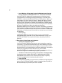
1. Grant of License
SOFTWARE includes software already installed on the SYSTEM (SYSTEM
SOFTWARE) and, if included in the SYSTEM package, software contained on the
CD-ROM disk and/or floppy disk(s) labeled “Desktop Software for Microsoft
Windows CE” (DESKTOP SOFTWARE). This EULA grants you the following rights
to the SOFTWARE:
•
SYSTEM SOFTWARE
You may use the SYSTEM SOFTWARE only as installed in the SYSTEM.
•
DESKTOP SOFTWARE
DESKTOP SOFTWARE might not be included with your SYSTEM. If DESKTOP
SOFTWARE is included with your SYSTEM, you may install and use the
component(s) of the DESKTOP SOFTWARE in accordance with the terms of
the end user license agreement provided with such component(s). In the
absence of a separate end user license agreement for particular component(s)
of the DESKTOP SOFTWARE, you may install and use only one (1) copy of
such component(s) on a single computer with which you use the SYSTEM.
vi
•
Use of Windows CE Operating System for Windows-based Terminal
Devices with Microsoft Windows NT Server, Terminal Server Edition
If the SOFTWARE is Windows CE operating system for Windows-based
Terminal devices, the following special provisions apply. In order to use the
SYSTEM in connection with Windows NT Server, Terminal Server Edition, you
must possess (1) a Client Access License for Windows NT Server, Terminal
Server Edition and (2) an end user license for Windows NT Workstation or an
end user license agreement for Windows NT Workstation for Windows-based
Terminal Devices (please refer to the end user license agreement for Windows
NT Server, Terminal Server Edition for additional information).
MANUFACTURER may have included a Certificate of Authenticity for Windows
NT Workstation for Windows-based Terminal Devices with the SYSTEM. In that
case, this EULA constitutes an end user license for the version of Windows NT
Workstation for Windows-based Terminal Devices indicated on such Certificate
of Authenticity.
•
Back-up Copy
If MANUFACTURER has not included a back-up copy of the SYSTEM
SOFTWARE with the SYSTEM, you may make a single back-up copy of the
SYSTEM SOFTWARE. You may use the back-up copy solely for archival
purposes.
2. Description of Other Rights and Limitations
•
Speech/Handwriting Recognition
If the SYSTEM SOFTWARE includes speech and/or handwriting recognition
component(s), you should understand that speech and handwriting recognition
are inherently statistical processes; that recognition errors are inherent in the
processes; that it is your responsibility to provide for handling such errors and to
monitor the recognition processes and correct any errors. Neither
MANUFACTURER nor its suppliers shall be liable for any damages arising out
of errors in the speech and handwriting recognition processes.
•
Limitations on Reverse Engineering, Decompilation and Disassembly
You may not reverse engineer, decompile, or disassemble the SYSTEM
SOFTWARE, except and only to the extent that such activity is expressly
permitted by applicable law notwithstanding this limitation.
•
Single SYSTEM
The SYSTEM SOFTWARE is licensed with the SYSTEM as a single integrated
product. The SYSTEM SOFTWARE installed in Read Only Memory (ROM) of
the SYSTEM may only be used as part of the SYSTEM.
vii
•
Single EULA
The package for the SYSTEM SOFTWARE may contain multiple versions of
this EULA, such as multiple translations and/or multiple media versions (e.g., in
the user documentation and in the software). Even if you receive multiple
versions of the EULA, you are licensed to use only one (1) copy of the SYSTEM
SOFTWARE.
•
Rental
You may not rent or lease the SOFTWARE.
•
Software Transfer
You may permanently transfer all of your rights under this EULA only as part of a
sale or transfer of the SYSTEM, provided you retain no copies, you transfer all
of the SOFTWARE (including all component parts, the media, any upgrades or
backup copies, this EULA and, if applicable, the Certificate(s) of Authenticity),
and the recipient agrees to the terms of this EULA. If the SOFTWARE is an
upgrade, any transfer must include all prior versions of the SOFTWARE.
•
Termination
Without prejudice to any other rights, MANUFACTURER or MS may terminate
this EULA if you fail to comply with the terms and conditions of this EULA. In
such event, you must destroy all copies of the SOFTWARE and all of its
component parts.
3. Upgrades
If the SYSTEM SOFTWARE and this EULA are provided separate from the
SYSTEM by MANUFACTURER and the SYSTEM SOFTWARE is on a ROM chip,
CD ROM disk(s) or floppy disk(s), and labeled “For ROM Upgrade Purposes Only”
(“ROM Upgrade”), you may install one copy of the ROM Upgrade onto the
SYSTEM as a replacement copy for the SYSTEM SOFTWARE originally installed
on the SYSTEM and use it in accordance with Section 1 of this EULA.
4. Copyright
All title and copyrights in and to the SOFTWARE (including but not limited to any
images, photographs, animations, video, audio, music, text and “applets,”
incorporated into the SOFTWARE), the accompanying printed materials, and any
copies of the SOFTWARE, are owned by MS or its suppliers (including Microsoft
Corporation). You may not copy the printed materials accompanying the
SOFTWARE. All rights not specifically granted under this EULA are reserved by
MS and its suppliers (including Microsoft Corporation).
viii
5. Product Support
Product support for the SOFTWARE is not provided by MS, its parent corporation,
Microsoft Corporation, or their affiliates or subsidiaries. For product support, please
refer to MANUFACTURER’s support number provided in the documentation for the
SYSTEM. Should you have any questions concerning this EULA, or if you desire to
contact MANUFACTURER for any other reason, please refer to the address
provided in the documentation for the SYSTEM.
6. Export Restrictions
You agree that you will not export or re-export the SOFTWARE to any country,
person, or entity subject to U.S. export restrictions. You specifically agree not to
export or re-export the SOFTWARE: (i) to any country to which the U.S. has
embargoed or restricted the export of goods or services, which as of March 1998
include, but are not necessarily limited to Cuba, Iran, Iraq, Libya, North Korea,
Sudan and Syria, or to any national of any such country, wherever located, who
intends to transmit or transport the products back to such country; (ii) to any person
or entity who you know or have reason to know will utilize the SOFTWARE or
portion thereof in the design, development or production of nuclear, chemical or
biological weapons; or (iii) to any person or entity who has been prohibited from
participating in U.S. export transactions by any federal agency of the U.S.
government.
If the SOFTWARE is labeled “North America Only Version” above, on the Product
Identification Card, or on the SOFTWARE packaging or other written materials,
then the following applies: The SOFTWARE is intended for distribution only in the
United States, its territories and possessions (including Puerto Rico, Guam, and
U.S. Virgin Islands) and Canada. Export of the SOFTWARE from the United States
is regulated under “EI controls” of the Export Administration Regulations (EAR, 15
CFR 730-744) of the U.S. Commerce Department, Bureau of Export Administration
(BXA). A license is required to export the SOFTWARE outside the United States or
Canada. You agree that you will not directly or indirectly, export or re-export the
SOFTWARE (or portions thereof) to any country, other than Canada, or to any
person or entity subject to U.S. export restrictions without first obtaining a
Commerce Department export license. You warrant and represent that neither the
BXA nor any other U.S. federal agency has suspended, revoked or denied your
export privileges.
7. Note on Java Support
The SYSTEM SOFTWARE may contain support for programs written in Java. Java
technology is not fault tolerant and is not designed, manufactured, or intended for
use or resale as on-line control equipment in hazardous environments requiring
fail-safe performance, such as in the operation of nuclear facilities, aircraft
navigation or communication systems, air traffic control, direct life support
machines, or weapons systems, in which the failure of Java technology could lead
directly to death, personal injury, or severe physical or environmental damage.
ix
8. Limited Warranty
•
Limited Warranty
MANUFACTURER warrants that the SOFTWARE will perform substantially in
accordance with the accompanying written materials for a period of ninety (90)
days from the date of receipt. Any implied warranties on the SOFTWARE are
limited to ninety (90) days. Some states/jurisdictions do not allow limitations on
duration of an implied warranty, so the above limitation may not apply to you.
•
Customer Remedies
MANUFACTURER’S and its suppliers’ entire liability and your exclusive remedy
shall be, at MANUFACTURER’S option, either (a) return of the price paid, or (b)
repair or replacement of the SOFTWARE that does not meet the above Limited
Warranty and which is returned to MANUFACTURER with a copy of your
receipt. This Limited Warranty is void if failure of the SOFTWARE has resulted
from accident, abuse, or misapplication. Any replacement SOFTWARE will be
warranted for the remainder of the original warranty period or thirty (30) days,
whichever is longer.
•
No Other Warranties
EXCEPT AS EXPRESSLY PROVIDED IN THE LIMITED WARRANTY
SECTION ABOVE, THE SOFTWARE IS PROVIDED TO THE END USER “AS
IS” WITHOUT WARRANTY OF ANY KIND, EITHER EXPRESSED OR
IMPLIED, INCLUDING, BUT NOT LIMITED TO, WARRANTIES OF NONINFRINGEMENT, MERCHANTABILITY, AND/OR FITNESS FOR A
PARTICULAR PURPOSE. THE ENTIRE RISK OF THE QUALITY AND
PERFORMANCE OF THE SOFTWARE IS WITH YOU.
•
No Liability for Consequential Damages
MANUFACTURER OR MANUFACTURER’S SUPPLIERS, INCLUDING MS
AND ITS SUPPLIERS, SHALL NOT BE HELD TO ANY LIABILITY FOR ANY
DAMAGES SUFFERED OR INCURRED BY THE END USER (INCLUDING,
BUT NOT LIMITED TO, GENERAL, SPECIAL, CONSEQUENTIAL OR
INCIDENTAL DAMAGES INCLUDING DAMAGES FOR LOSS OF BUSINESS
PROFITS, BUSINESS INTERRUPTION, LOSS OF BUSINESS
INFORMATION AND THE LIKE), ARISING FROM OR IN CONNECTION WITH
THE DELIVERY, USE OR PERFORMANCE OF THE SOFTWARE.
If you acquired this EULA in the United States, this EULA is governed by the laws
of the State of Washington.
If you acquired this EULA in Canada, this EULA is governed by the laws of the
Province of Ontario, Canada. Each of the parties hereto irrevocably attorns to the
jurisdiction of the courts of the Province of Ontario and further agrees to commence
any litigation which may arise hereunder in the courts located in the Judicial District
of York, Province of Ontario.
x
If this EULA was acquired outside the United States, then local law may apply.
Should you have any questions concerning this EULA, please contact the
MANUFACTURER of your SYSTEM.
U.S. GOVERNMENT RESTRICTED RIGHTS
The SOFTWARE and documentation are provided with RESTRICTED RIGHTS.
Use, duplication, or disclosure by the Government is subject to restrictions as set
forth in subparagraph (c)(1)(ii) of the Rights in Technical Data and Computer
Software clause at DFARS 252.227-7013 or subparagraphs (c)(1) and (2) of the
Commercial Computer Software—Restricted Rights at 48 CFR 52.227- 19, as
applicable. MANUFACTURER is Microsoft Corporation/One Microsoft Way/
Redmond, WA 98052-6399.
xi
FCC Statement
This equipment has been tested and found to comply with the limits for either Class
A or Class B digital devices (refer to “Terminal Requirements Compliance”),
pursuant to Part 15 of the FCC Rules. These limits are designed to provide
reasonable protection against harmful interference in a residential installation. This
equipment generates, uses, and can radiate radio frequency energy and, if not
installed and used in accordance with the instructions, may cause harmful
interference to radio communications. However, there is no guarantee that
interference will not occur in a particular installation. If this equipment does cause
harmful interference to radio or television reception, which can be determined by
turning the equipment off and on, the user is encouraged to try to correct the
interference by one or more of the following measures:
•
Reorient or relocate the receiving antenna.
•
Increase the separation between the equipment and the receiver.
•
Connect the equipment into an outlet on a circuit different from that to which the
receiver is connected.
•
Consult the dealer or an experienced radio/TV technician for help.
Caution
Changes or modifications not covered in this manual
must be approved in writing by the manufacturer’s
Regulatory Engineering department. Changes or
modifications made without written approval may void
the user’s authority to operate the equipment.
Terminal Requirements Compliance
FCC Compliance
Models T1000 and T1010 terminals meet Class B requirements.
IEC/EN Compliance
Models T1000 and T1010 terminals meet Class B requirements.
Canadian DOC Notices
Refer to the previous section, “Terminal Requirements Compliance,” to find out to
which terminal model each of the statements below refers.
xii
Class A
This digital apparatus does not exceed the Class A limits for radio noise emissions
from digital apparatus set out in the Radio Interference Regulations of the
Canadian Department of Communications.
Le présent appareil numérique n’émet pas de bruits radioélectriques dépassant les
limites applicables aux appareils numériques de la classe A prescrites dans le
Réglement sur le brouillage radioélectrique édicté par le Ministère des
Communications du Canada.
Class B
This digital apparatus does not exceed the Class B limits for radio noise emissions
from digital apparatus set out in the Radio Interference Regulations of the
Canadian Department of Communications.
Le présent appareil numérique n’émet pas de bruits radioélectriques dépassant les
limites applicables aux appareils numériques de la classe B prescrites dans le
Réglement sur le brouillage radioélectrique édicté par le Ministère des
Communications du Canada.
IEC/EN Notice
This product conforms to the requirements of IEC950 and EN60950.
This product conforms to requirements of EN55022 for Class A equipment or
EN55022 for Class B equipment (refer to “Terminal Requirements Compliance”).
T10x0 Series Windows-based Terminals
For use with External Power Supply DVE Model DSA-0301-05 or Potrans Model
UP01811050A or certified equivalent model supplied by the manufacturer, rated
minimum 5V/4A.
Noise Suppressor
A noise suppressor (ferrite bead) must be installed on the network cable of your
terminal. This installation is necessary to maintain compliance with U.S. FCC B
limits and European CISPR B EN55022 Class B limits. The noise suppressor is
supplied by the manufacturer and is packed in your terminal’s shipping carton.
xiii
Cable Notice
The use of shielded I/O cables is required when connecting this equipment to any
and all optional peripheral or host devices. Failure to do so may cause interference
and violate FCC and international regulations for electromagnetic interference.
xv
License Agreement
YOU SHOULD CAREFULLY READ THE FOLLOWING TERMS AND
CONDITIONS BEFORE USING THIS SOFTWARE (TOGETHER WITH ANY
SUPPLIED DOCUMENTATION, HEREAFTER "SOFTWARE"), WHICH IS OWNED
BY THE MANUFACTURER OR ITS LICENSORS. USING THIS SOFTWARE
INDICATES YOUR ACCEPTANCE OF THE FOLLOWING TERMS AND
CONDITIONS. THE MANUFACTURER’S LICENSORS ARE INTENDED
THIRD-PARTY BENEFICIARIES UNDER THIS AGREEMENT.
Grant
You may use the Software in or in conjunction with Your manufacturer-produced
hardware (Terminal). You have the right to use this Software by loading it onto a
computer containing the capability of transferring the Software (in whole or in part)
to the manufacturer-produced hardware. You may use the Software in this fashion
as many times as necessary, so long as such use is always in conjunction with the
manufacturer-produced Terminal. You may transfer ownership of the Terminal and
equipment, including the right to use the Software to another party so long as that
party agrees to accept these terms and conditions.
YOU MAY NOT USE, COPY, MODIFY, TRANSLATE OR TRANSFER THE
SOFTWARE, OR MODIFICATION THEREOF, IN WHOLE OR IN PART, EXCEPT
AS EXPRESSLY PROVIDED FOR IN THIS LICENSE. YOU MAY NOT
DECOMPILE, REVERSE ENGINEER OR OTHERWISE DECODE OR ALTER
THE SOFTWARE.
Disclaimer of Warranty
This Software is provided, "AS IS", and is delivered with no warranties, either
express or implied.
MANUFACTURER MAKES AND YOU RECEIVE NO WARRANTIES ON THE
FIRMWARE, EXPRESS, IMPLIED, OR STATUTORY, OR IN ANY OTHER
PROVISION OF THIS AGREEMENT OR COMMUNICATION WITH YOU, AND
MANUFACTURER DISCLAIMS ANY IMPLIED WARRANTIES OF
MERCHANTABILITY, NON-INFRINGEMENT AND FITNESS FOR ANY
PARTICULAR PURPOSE. MANUFACTURER DOES NOT WARRANT THAT THE
FUNCTIONS CONTAINED IN THE PRODUCT WILL MEET YOUR
REQUIREMENTS OR THAT THE OPERATION WILL BE UNINTERRUPTED OR
ERROR FREE.
xvi
SOME STATES DO NOT ALLOW LIMITATIONS ON HOW LONG AN IMPLIED
WARRANTY LASTS SO THE ABOVE LIMITATION MAY NOT APPLY TO YOU.
THIS WARRANTY GIVES YOU SPECIFIC LEGAL RIGHTS. YOU MAY ALSO
HAVE OTHER RIGHTS WHICH VARY FROM STATE TO STATE.
Limit of Liability
UNDER NO CIRCUMSTANCES SHALL MANUFACTURER BE LIABLE FOR
LOSS OF DATA, COST OF COVER, OR ANY INCIDENTAL OR
CONSEQUENTIAL DAMAGES, HOWEVER CAUSED AND ON ANY THEORY OF
LIABILITY. THESE LIMITATIONS SHALL APPLY EVEN IF MANUFACTURER OR
ITS RESELLER HAS BEEN ADVISED OF THE POSSIBILITY OF SUCH
DAMAGES, AND NOTWITHSTANDING ANY FAILURE OF ESSENTIAL
PURPOSE OF ANY LIMITED REMEDY PROVIDED HEREIN.
YOU AGREE THAT THESE ARE THE ONLY APPLICABLE TERMS OF
AGREEMENT BETWEEN US COVERING SOFTWARE AND THAT THEY
SUPERSEDE ANY OTHER COMMUNICATIONS (ORAL OR WRITTEN)
BETWEEN US RELATING TO THE SOFTWARE.
Export Restrictions
You agree You will not export or transmit the Software to any country to which
export is restricted by applicable US law or regulation without the written approval
of the appropriate US Government organization.
U.S. Government Restricted Rights
The Software is provided with RESTRICTED RIGHTS. Use, duplication or
disclosure by the Government is subject to restrictions as set forth in subparagraph
(c)(1)(ii) of the Rights in Technological Data and computer software clause at
DFARS 252.227-7013 or in subparagraphs (c)(1) and (2) of the Commercial
Computer Software-Restricted Rights at 8 C.F.R. 52-227-19 as applicable.
Contents
Patents
iii
About the Administrators Guide
Guide Overview xxv
Guide Conventions xxvi
Text Format xxvi
User Interface Menu Control
xxvii
Terminal Installation
1
Model T1000 Terminal Installation
Locating the Terminal 3
Connecting the Terminal 3
Mounting the Terminal 7
Freestanding Desktop Mounting
Turning On the Terminal 8
2
Model T1010 Terminal Installation
Locating the Terminal 9
Connecting the Terminal 9
Mounting the Terminal 13
Freestanding Desktop Mounting
Turning On the Terminal 14
Advanced User Interface
3
7
Initial Terminal Setup
13
xviii
Using the Setup Wizard
4
17
Changing Terminal Properties
Using the Terminal Properties Dialog Box 39
Resetting to Factory Defaults 40
Terminal Settings Change Dialog Box 41
5
Network Configuration
Using the Network Properties Sheet
6
Web Browser
Using the Web Properties Sheet
7
43
47
Additional Terminal Applications
Using the Apps Properties Sheet 51
8
ICA Client Settings
Using the Global ICA Client Settings Dialog Box
Setting the Default Hotkeys 56
Setting Terminal Preferences 57
Setting the Server Location 59
Setting Up a SOCKS Firewall 61
Setting Up a PNLite 63
56
Connection Configuration
9
Creating New Connections
Using the New Connection Dialog Box 67
Choosing a Connection Protocol 68
Using the Startup Function 69
10
ICA Connections
Using the ICA Connections Wizard
Network Connections 72
Dial-In Connection 79
11
71
Dial-Up Connections
Using the Dial-Up Configuration Wizard
12
81
Dial-Up Dialing Properties and Configuration
Using the Dialing Properties Dialog Box
87
xix
Using the Device Properties Dialog Box 90
Port Settings 91
Call Options 92
13
Dial-Up TCP/IP Settings and Security
Using the TCP/IP Settings Dialog Box 93
Using the Security Settings Dialog Box 94
14
Dial-Up Scripts
Using the Dial-Up Scripts Dialog Boxes
15
97
RDP Connections
Using the WTS Connection Wizard 101
16
Terminal Emulation Connections
Using the TE Client Connection Wizard
17
107
TCP/IP Telnet Configuration
Using the TCP/IP Telnet Configuration Dialog Box 117
Using the Modem Settings Dialog Box 121
Using the Configuration of Serial Cable on Com1 (or Com2) Dialog
Box 122
18
Internet Explorer Connections
19
Editing ICA Connections
Using the Edit Connection Details Dialog Box 128
Using the Server Properties Sheet 128
Using the Application Properties Sheet 130
Using the Logon Properties Sheet 131
Using the Window Properties Sheet 132
Using the Options Properties Sheet 134
Using the Title Properties Sheet 136
Using the Firewall Settings Properties Sheet 137
20
Editing RDP, Dial-Up, and Terminal Emulation Connections
Dial-Up and Terminal Emulation Connections 139
RDP Connections 139
Using the Edit Connection Dialog Box 140
xx
Using the Net Connections Properties Sheet 141
Using the Application Properties Sheet 142
External Devices
21
Devices Properties
Devices Properties Sheet
22
147
Managing Network Adapters
Using the Adapters Configuration Dialog Box
IP Address Properties Sheet 153
Name Server Properties Sheet 154
23
152
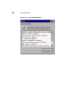
Add-On
Add-on Dialog Box Uninstall Tab 155
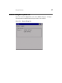
Add-on Dialog Box System Tab 157
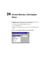
24
Aironet Wireless LAN Adapter Setup
Using the Aironet Dialog Box
25
160
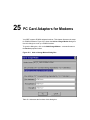
PC Card Adapters for Modems
ISDN Settings 163
26
Touchscreens
ELO Touchscreen 165
MicroTouch Touchscreen 167
Hardware Properties Sheet 168
Cursor Properties Sheet 169
Touch Settings Properties Sheet 171
Calibrate Properties Sheet 172
27
Date/Time Properties
28
JETCET PRINT
29
Local Printers
LPD Printing 181
Using the LPD Config Dialog Box 182
RDP Printing 182
Printers Properties Sheet 182
Using the Printer Properties Dialog Box 185
xxi
30
PC Card Adapters for Token Ring Networks
Using the RACORE - Token Ring Adapter Settings Dialog Box
31
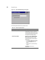
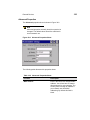
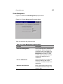
SNTP Client
Using the SNTP Client Dialog Box
32
189
PC Card Adapters for Wireless Networks
Using the WaveLAN/IEEE Settings Dialog Box
Basic Properties Sheet 191
Advanced Properties 193
Power Management 195
Encryption 196
33
191
Volume Properties
Using the Volume Properties Dialog Box 198
Firmware Upgrades
34
Cable Firmware Upgrades
Setup 202
Parallel Flash Download Procedure 202
Manual Download 203
Cable Pinouts 204
Parallel Download Cable Pinouts 204
35
FTP Pull Firmware Upgrades
Using the Upgrade Properties Sheet
FTP and Params.ini 210
The Upgrade Process 210
36
207
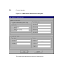
SNMP Firmware Upgrades
Using the SNMP Network Administration Dialog Box 213
The Upgrade Process 216
37
DHCP Firmware Upgrades
Using the Change DHCP Option IDs Dialog Box
The Upgrade Process 222
Manual DHCP Firmware Upgrades 223
219
187
xxii
Client Security
38
Security Properties
Using the Security Properties Sheet 227
39
Terminal Accounts
Guest Accounts 233
User Accounts 234
Administrator Accounts 234
Using Terminal Accounts 234
40
Creating Terminal Accounts
Using the Add User Account Dialog Box 237
41
Modifying and Deleting Terminal Accounts
Using the Modify User Account Dialog Box
Deleting Terminal Accounts 248
42
243
Terminal Login
Logging Into the Terminal 249
Autologin and Autoconnect 250
Autologin 250
AutoStart 250
Single Button Connect 251
43
Failover
Getting Help
44
Windows-based Terminal Specifications
45
How to...
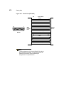
46
Terminal Port Pin Assignments
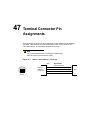
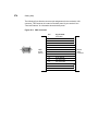
47
Terminal Connector Pin Assignments
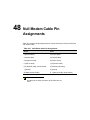
48
Null Modem Cable Pin Assignments
49
Modem AT Commands
A
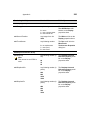
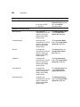
SNMP Remote Configuration Chart
xxiii
B
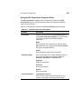
NFuse Server Configuration Requirements
Introduction 303
PNLite Access 303
Browser-Based Access
Glossary 305
303
About the Administrators Guide
The T1000/T1010 Series Windows-based Terminal Administrators Guide contains
the information you will need to install, configure, connect, and troubleshoot a WBT
(Windows-based Terminal). This guide is written for network system administrators
and covers the Models T1000 and T1010 terminals.
Guide Overview
The administrators guide consists of the following chapters:
•
Terminal Installation
•
Advanced User Interface
•
Connection Configuration
•
External Devices
•
Firmware Upgrades
•
Client Security
•
Getting Help
This guide contains information about:
•
Terminal specifications and installations
•
The WBT user interface
•
Physical and network connections, and protocols supported
•
Firmware upgrades
•
Terminal security
•
Getting help
xxvi
Guide Conventions
Text Format
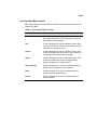
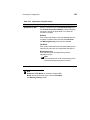
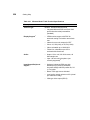
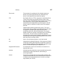
Table 1 lists the text format conventions used in this document.
Table 1 Text Format Conventions
Convention
Where Used
Italic
New term, book title, or emphasis.
Bold
Screen display, keycaps, and user input.
+
Note
This convention indicates a note. A note adds
information.
Caution
This convention indicates a caution. A caution
indicates actions that may cause damage to
equipment, erase files, or destroy data.
Keystroke sequences such as:
Ctrl+Alt+Del
|
Instructions about invoking a menu such as:
Network | SNMP Network | Location
xxvii
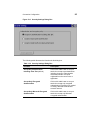
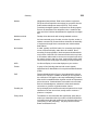
User Interface Menu Control
Table 2 describes the command buttons used for user interface menu control on a
T1000/T1010 WBT.
Table 2 User Interface Menu Control
Command Button
Function
X
Found in the upper right corner of a dialog box. Click on
this command button to quit a dialog box or properties
sheet without saving changes.
OK
Found in dialog boxes and on properties sheets. Click
on this command button to save your changes and quit
a dialog box or properties sheet.
Cancel
Found in dialog boxes and on properties sheets. Click
on this command button at any time to quit a dialog box
or properties sheet without saving changes.
Apply
Found in dialog boxes and on properties sheets. Click
on this command button to save changes without
quitting a dialog box or properties sheet.
Next or Accept
Found in wizards. Click on these command buttons to
display the next dialog box in the sequence.
Back
Found in wizards. Click on this command button to
return to the previous dialog box.
Finish
Found in wizards. Click on this command button to
finish the wizard.
Terminal Installation
1
2
Model T1000 Terminal Installation
Model T1010 Terminal Installation
1
Model T1000 Terminal
Installation
This section discusses the procedures for installing the T1000 terminal.
Note
A keyboard and AC power cord are supplied with U.S.
models only.
Locating the Terminal
Position the terminal on a clean, horizontal surface that is free from vibration and
out of direct sunlight. Refer to “Windows-based Terminal Specifications” for
environmental specifications.
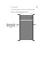
Connecting the Terminal
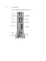
Make all connections to the back panel before connecting the terminal to power.
Figure 1-1 shows a terminal’s back panel connectors.
4
Terminal Installation
Figure 1-1 T1000 Terminal Back Panel Connectors
5
Terminal Installation
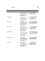
The following table summarizes the back panel connectors’ functions.
Table 1-1 T1000 Terminal Back Panel Connectors
Connector
Description
Network Connector
LAN connector, 10/100Base-T
Com1
Serial port 1. Can be connected to:
Com2
•
External modem.
•
Local server.
•
Local serial printer.
•
Touch-screen monitor.
Serial port 2. Can be connected to:
•
External modem.
•
Local server.
•
Local serial printer.
•
Touch-screen monitor.
Parallel Port
Local printer output
Video
Monitor interface
Keyboard
Keyboard interface
Mouse
PS-2 mouse interface
USB
Keyboard and mouse.
Power
Power module cable interface
Option Slot
PCMCIA card slot
Headphone
Audio output for headphones or powered speakers
Microphone
Audio input for microphones (currently not supported)
6
Terminal Installation
Proceed as follows to connect the terminal. (If necessary, remove the desktop
mounting stand (one Phillips-head screw on the bottom.)
Note
Before connecting the cables, decide which mounting
configuration will be used and ensure that the cables
are of the correct lengths. If permanent desktop
configuration is to be used, drill the desktop mounting
holes before connecting the cables.
1. Connect the monitor to the Video connector.
2. Connect the keyboard to the Keyboard connector.
3. Connect the mouse to the Mouse connector.
4. If you will be using a network connection, connect a 10Base-T or 100Base-T
network cable to the Network connector. Be sure to install the supplied noise
suppressor on the cable.
5. Depending on your configuration needs, connect a printer to the parallel port,
and/or connect a modem/server serial cable to the serial ports, as appropriate.
6. Connect the power supply output cable to the Power connector.
Caution
Do not force a connector into its socket. If any undue
resistance is encountered, ensure that the connector is
oriented correctly to the socket.
7. Plug the AC cord into the power supply, then into an AC outlet.
8. After the cables are connected, install the terminal in its planned location (see
the next section “Mounting the Terminal”).
Terminal Installation
7
Mounting the Terminal
Instructions for mounting your terminal are provided in the following paragraphs.
Freestanding Desktop Mounting
The terminal is shipped with a desktop mounting stand attached so it can
immediately be put into desktop operation. The mounting stand is weighted and
equipped with non-skid feet. A single screw attaches the mounting stand to the
terminal housing. The following figure shows the terminal mounted on the desktop
mounting stand.
Figure 1-2 T1000 Freestanding Desktop Mounting
8
Terminal Installation
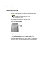
Turning On the Terminal
Once the terminal is installed and all back panel connections have been made,
power it up. It is powered-up and operating when the power supply is connected to
AC power; to toggle the display off or on, press and release the power button.
Note
If the button is continuously depressed for 3-5 seconds,
the unit will perform a hard boot.
See the following figure for the location of the power button.
Figure 1-3 T1000 Power Button
The splash screen will appear, followed by:
•
The Setup Wizard, if it is the first time that you have turned on your terminal.
•
The Connection Manager dialog box, if the Setup Wizard has been
completed.
Adjustments to the display can be made at any time, whether or not the terminal is
connected to a server. See “Changing Terminal Properties” for more information.
2
Model T1010 Terminal
Installation
This section discusses the procedures for installing the T1010 terminal. The
following sections describe how to connect and set up the terminals.
Note
A keyboard and AC power cord are supplied with U.S.
models only.
Locating the Terminal
Position the terminal on a clean, horizontal surface that is free from vibration and
out of direct sunlight. Refer to “Windows-based Terminal Specifications” for
environmental specifications.
Connecting the Terminal
Make all connections to the back panel before connecting the terminal to power.
Figure 2-1 shows a terminal’s back panel connectors.
10
Terminal Installation
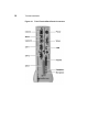
Figure 2-1 T1010 Terminal Back Panel Connectors
11
Terminal Installation
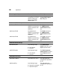
The following table summarizes the back panel connectors’ functions.
Table 2-1 T1010 Terminal Back Panel Connectors
Connector
Description
Network Connector
LAN connector, 10/100Base-T
Com1
Serial port 1. Can be connected to:
Com2
•
External modem.
•
Local server.
•
Local serial printer.
•
Touch-screen monitor.
Serial port 2. Can be connected to:
•
External modem.
•
Local server.
•
Local serial printer.
•
Touch-screen monitor.
Parallel Port
Local printer output
Video
Monitor interface
Keyboard
Keyboard interface
Mouse
PS-2 mouse interface
USB
USB interface
Power
Power module cable interface
Option Slot
PCMCIA card slot
Headphone
Audio output for headphones or powered speakers
Microphone
Audio input for microphones (currently not supported)
12
Terminal Installation
Proceed as follows to connect the terminal. (If necessary, remove the desktop
mounting stand (one Phillips-head screw on the bottom.)
Note
Before connecting the cables ensure that the cables
are of the correct lengths. If permanent desktop is to be
used, drill the desktop mounting holes before
connecting the cables.
1. Connect the monitor to the Video connector.
2. Connect the keyboard to the Keyboard connector.
3. Connect the mouse to the Mouse connector.
4. If you will be using a network connection, connect a 10Base-T or 100Base-T
network cable to the Network connector. Be sure to install the supplied noise
suppressor on the cable.
5. Depending on your configuration needs, connect a printer to the parallel port,
and/or connect a modem/server serial cable to the serial ports, as appropriate.
6. Connect the power supply output cable to the Power connector.
Caution
Do not force a connector into its socket. If any undue
resistance is encountered, ensure that the connector is
oriented correctly to the socket.
7. Plug the AC cord into the power supply, then into an AC outlet.
8. After the cables are connected, install the terminal in its planned location (see
the next section “Mounting the Terminal”).
Terminal Installation
13
Mounting the Terminal
Instructions for mounting your terminal are provided in the following paragraphs.
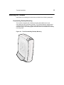
Freestanding Desktop Mounting
The terminal is shipped with a desktop mounting stand attached so it can
immediately be put into desktop operation. The mounting stand is weighted and
equipped with non-skid feet. A single screw attaches the mounting stand to the
terminal housing. The following figure shows the terminal mounted on the desktop
mounting stand.
Figure 2-2 T1010 Freestanding Desktop Mounting
14
Terminal Installation
Turning On the Terminal
Once the terminal is installed and all back panel connections have been made,
power it up. It is powered-up and operating when the power supply is connected to
AC power; to toggle the display off or on, press and release the power button.
Note
If the button is continuously depressed for 3-5 seconds,
the unit will perform a hard boot.
See the following figure for the location of the power button.
Figure 2-3 T1010 Power Button
The splash screen will appear, followed by:
•
The Setup Wizard, if it is the first time that you have turned on your terminal.
•
The Connection Manager dialog box, if the Setup Wizard has been
completed.
Adjustments to the display can be made at any time, whether or not the terminal is
connected to a server. See “Changing Terminal Properties” for more information.
Advanced User Interface
8
9
10
11
12
13
Initial Terminal Setup
Changing Terminal Properties
Network Configuration
Web Browser
Additional Terminal Applications
ICA Client Settings
3
Initial Terminal Setup
The Setup Wizard is used for initial setup of the terminal’s properties. The wizard
runs when:
•
You power-up your terminal for the first time.
•
An image has been downloaded to your terminal that is older than the image
currently in use.
•
You use the Reset the Terminal to Factory-Default Property Settings
function on the General properties sheet, or you reset the terminal using a
hot-key procedure under direction of the factory.
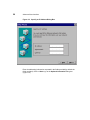
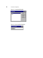
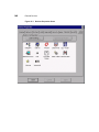
Using the Setup Wizard
The Setup Wizard lets you set terminal network configuration and terminal display
parameters. Several dialog boxes display in succession during the process. Each
dialog box is self-explanatory. Some dialog boxes are informational and require no
user input. Other dialog boxes prompt you for network, printer, and display
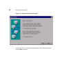
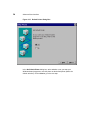
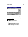
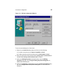
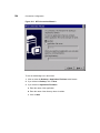
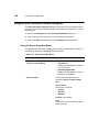
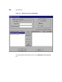
information. See Figure 3-1 to view the Welcome/Countdown dialog box, which is
the first dialog box of the wizard.
Note
Any future changes to settings that were made using
the wizard can be made using the Terminal Properties
dialog box. Launch this dialog box from the
Connection Manager by pressing the F2 key. See
“Changing Terminal Properties.”
18
Advanced User Interface
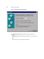
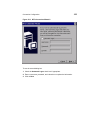
Figure 3-1 Welcome/Countdown Dialog Box
The Welcome/Countdown dialog box provides product information and a
countdown.
•
Click on Next during the countdown before it reaches zero to continue with the
wizard.
Or
•
Let the count go to zero to auto-configure the terminal.
Advanced User Interface
19
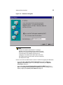
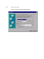
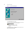
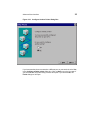
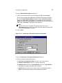
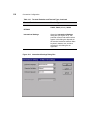
Figure 3-2 IP Address Dialog Box
Note
Contact the network administrator if a message
appears in the box indicating that no network services
were found. It may be that the network is not connected
to the terminal or the network services are not
configured. The default active radio button in this box
will be No if network services were not found; otherwise
the default will be Yes.
Click on one of the two radio buttons to select a method for supplying IP addresses:
•
If you select No, I will enter static IP information and click on Next, the
Specify an IP Address (Figure 3-3) will display, followed by the Optional
Information dialog box.
•
If you select Yes, use the IP information supplied by DHCP and click on
Next, the Desktop Area and Refresh Frequency (Figure 3-5) dialog box will
display, skipping the Specify an IP Address dialog box.
20
Advanced User Interface
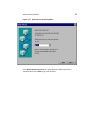
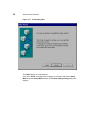
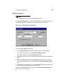
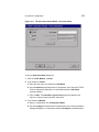
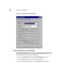
Figure 3-3 Specify an IP Address Dialog Box
Enter the addressing information requested in the fields provided (by default the
fields are blank). Click on Next to go to the Optional Information dialog box
(Figure 3-4).
Advanced User Interface
21
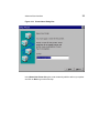
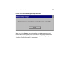
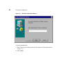
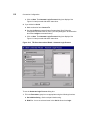
Figure 3-4 Optional Information Dialog Box
Check a box to enable name resolution:
•
Enable DNS - Enables Domain Name Services
•
Enable WINS - Enables Windows Internet Naming Services
Enter the information in the text fields that are active. By default the check boxes
are unselected and the text fields are inactive. Click on Next to go to the next step.
22
Advanced User Interface
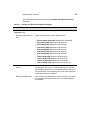
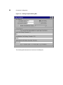
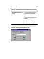
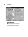
Figure 3-5 Desktop and Keyboard Settings Dialog Box
Advanced User Interface
23
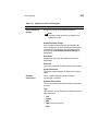
The following table lists the functions of the Desktop and Keyboard Settings
dialog box.
Table 3-1
Desktop and Keyboard Settings Dialog Box
Function
Description
Desktop Area and Refresh
Frequency area:
Resolution drop-down list
box
Select a resolution from the list. Selections are:
•
Best Available Using DDC Supported in all terminals.
•
640 x 480 @ 60Hz Supported in all terminals.
•
640 x 480 @ 75Hz Supported in all terminals.
•
640 x 480 @ 85Hz Supported in all terminals.
•
800 x 600 @ 60Hz Supported in all terminals.
•
800 x 600 @ 75Hz Supported in all terminals.
•
800 x 600 @ 85Hz Supported in all terminals.
•
1024 x 768 @ 60Hz Supported in all terminals.
•
1024 x 768 @ 75Hz Supported in all terminals.
•
1024 x 768 @ 85 Hz Supported in all terminals.
•
1280 x 1024 @ 60 Hz Supported in the T1010 only.
Color Palette drop-down
list box
Select the color resolution for applications used with the
terminal (8-bit, 256 colors or 16-bit, 65,536 colors). Typically,
256 would be selected for ICA and 65536 would be selected if
the local browser is used (although use of the lower resolution
may help the terminal run faster).
Test... command button
Click on this command button to test the selections you made
in the drop-down list boxes in this area. The following dialog
box displays:
24
Table 3-1
Advanced User Interface
Desktop and Keyboard Settings Dialog Box, Continued
Function
Description
Clicking Ok displays a color test pattern. After the test pattern
closes, respond to the prompt(s) to accept or reject the new
settings.
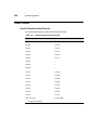
Keyboard area
Select the keyboard nationality in the Locale drop-down list
box. Check the NumLock on Boot check box if you want the
numeric keypad to be active when the terminal boots. The
following keyboard mappings are supported by the firmware:
Belgian Dutch
Belgian French
Brazilian (ABNT)
Canadian Eng (Multi)
Canadian FR (Multi)
Canadian French
Croatian
Czech
Danish
Dutch
English (UK)
English (US)
Finnish
French
German
Greek
Hungarian
Italian
Italian (142)
Japanese
Latin American
Norwegian
Polish (214)
Polish (Programmers)
Portuguese
Romanian
Slovak
Slovenian
Spanish
Spanish Variation
Swedish
Swiss French
Swiss German
Turkish F
Turkish Q
US International
Advanced User Interface
25
After making a new selection or accepting the default, click on Next ro go to the
Browser Setup dialog box.
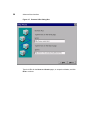
Figure 3-6 Browser Setup Dialog Box
Select whether or not to set up a local browser, and click Next to the next step. If
you selected Yes, the Browser URLs dialog box (Figure 3-7) displays. If you
selected No, the browser setup is skipped and the Local Printer Setup dialog box
(Figure 3-11) is displayed.
26
Advanced User Interface
Figure 3-7 Browser URLs Dialog Box
Type the URLs for the Home and Search pages, or accept the defaults, and click
Next to continue.
Advanced User Interface
27
Figure 3-8 Preferences Dialog Box
Select the desired preferences or accept the defaults, and click Next to continue.
28
Advanced User Interface
Figure 3-9 History and Favorites Dialog Box
Uncheck the boxes or accept the defaults (checked) for the indicated selections,
and click Next to continue.
Advanced User Interface
29
Figure 3-10 Proxy Server Dialog Box
If your terminal accesses the Internet through a proxy server, check the Use proxy
server box and make the required entries in the now-enabled text and check
boxes, and click Next to continue to the Local Printer Setup dialog box
(Figure 3-11).
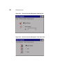
30
Advanced User Interface
Figure 3-11 Local Printer Setup Dialog Box
The Local Printer Setup dialog box displays.
If you want to set up a printer connected locally to your terminal, select Yes and the
dialog boxes that follow will prompt you for printer information.
Note
This local printer setup applies only to RDP
connections. See “Local Printers” for further
information.
If you select No (the default), you will skip the remaining printer dialog boxes and
the Finish dialog box (Figure 3-17) will display.
Make your selection and click on Next.
Advanced User Interface
Figure 3-12 Select Printer Port Dialog Box
In the Select Printer Port dialog box, select the port to which the printer is
connected and click on Next to go to the next step.
31
32
Advanced User Interface
Figure 3-13 Select Printer Model Dialog Box
In the Select the Printer Model dialog box, select the printer model from the list
and click on Next to go to the next step.
Advanced User Interface
33
Figure 3-14 Printer Name Dialog Box
In the Name Your Printer dialog box, enter a name by which to refer to your printer
and click on Next to go to the next step.
34
Advanced User Interface
Figure 3-15 Default Printer Dialog Box
In the Set Default Printer dialog box, select whether or not you want your
Windows-based programs to use this printer as the default printer (Yes is the
default selection). Click on Next to go to the next step.
Advanced User Interface
35
Figure 3-16 Configure Another Printer Dialog Box
If you have another printer connected to a different port on your terminal, select Yes
in the Configure another printer dialog box. Click on Next to go to the next step. If
you selected Yes, the printer setup process will repeat. If you selected No, the
Finish dialog box will open.
36
Advanced User Interface
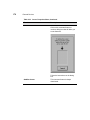
Figure 3-17 Finish Dialog Box
The Finish dialog box is informational.
Click on the Finish command button to apply your selections and quit the Setup
Wizard. After the Setup Wizard closes, the Terminal Settings Change dialog box
displays.
Advanced User Interface
37
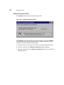
Figure 3-18 Terminal Settings Change Dialog Box
When you click on Restart, the terminal will go through the boot process and
restart in the normal operating mode. If you want to change any of the selections
after you restart, press F2 to open the Terminal Properties dialog box (see
“Changing Terminal Properties” for instructions).
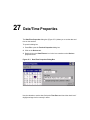
4
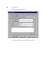
Changing Terminal Properties
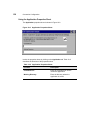
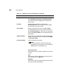
Terminal properties can be changed or reconfigured at any time during normal
terminal operation using the Terminal Properties dialog box. Figure 4-1 shows this
dialog box.
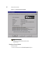
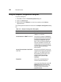
Using the Terminal Properties Dialog Box
Invoke the Terminal Properties dialog box by pressing the F2 key from the
Connection Manager.
The Terminal Properties dialog box consists of a total of 11 properties sheets that
can be invoked by clicking on their individual tabs. The following 6 sheets are used
to change terminal properties:
•
Network - discussed in “Network Configuration”
•
Upgrade - beginning with “Cable Firmware Upgrades”.
•
Security - beginning with “Security Properties”
•
Web - discussed in “Web Browser”
•
Apps - beginning with “Additional Applications”
•
Devices - beginning with “Devices Properties
•
Printers - discussed in “Local Printers”
The General, SysInfo, Input, and Display properties sheets are discussed in
“General Terminal Information” and “Display Configuration” and “Keyboard and
Mouse Configuration” in the T10x0 Series WBT Users Guide.
40
Advanced User Interface
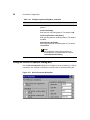
Figure 4-1 Terminal Properties Dialog Box
Note
The amount of available RAM may differ between
terminal models.
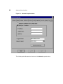
Resetting to Factory Defaults
Proceed as follows:
1. Click on the General tab of the Terminal Properties dialog box.
Advanced User Interface
41
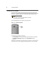
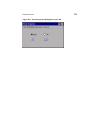
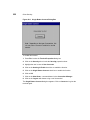
2. Click on the Reset the Terminal to Factory Default Property Settings check
box. Figure 4-2 shows the System Settings Change dialog box that displays.
3. Click on Yes to start the reset process. The terminal will restart with the factory
defaults in effect. The Setup Wizard displays when the terminal resets.
Note
If the above reset procedure fails, call technical support
at Compaq (800-OKCOMPAQ) for instructions on using
a hot-key reset procedure.
Figure 4-2 System Settings Change Dialog Box
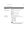
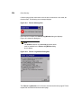
Terminal Settings Change Dialog Box
When you change terminal properties using the Setup Wizard or the Terminal
Properties dialog box, you will click on either the Finish or OK command button to
save your new settings and close the application. The Terminal Settings Change
dialog box will then display. Figure 4-3 shows the Terminal Settings Change
dialog box.
42
Advanced User Interface
Figure 4-3 Terminal Settings Change Dialog Box
This dialog box contains the Restart command button. The terminal must be
restarted in order for your new settings to take effect. Click on Restart to restart the
terminal. The Connection Manager displays. See “Connections Management” for
detailed information about configuring and making terminal connections.
5
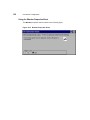
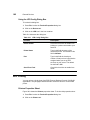
Network Configuration
The Network properties sheet lets you configure your network. See Figure 5-1 to
view this properties sheet.
Using the Network Properties Sheet
To invoke this properties sheet:
1. Press F2 to invoke the Terminal Properties dialog box.
2. Click on the Network tab.
44
Advanced User Interface
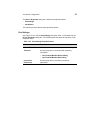
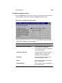
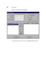
Figure 5-1 Network Properties Sheet
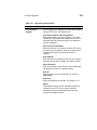
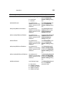
The following table discusses the functions of the Network properties sheet.
45
Advanced User Interface
Table 5-1
Network Properties Sheet
Function
Description
Obtain an Address from a
DHCP Server
Click on this radio button to enable DHCP addressing. An IP
address will be automatically assigned to your terminal by the
DHCP server.
Specify an IP Address
Use this group box to enter a specific IP address.
IP Address
Enter a static IP address in this field.
Subnet Mask
Enter the subnet mask of the IP address.
Gateway
Enter the gateway of the IP address.
Terminal Name
Enter a name of your choice for the terminal.
Network Speed
Use this scroll list to select a network communication speed.
The choices are (in Mb/s):
•
Auto Detect (default)
•
10 Mbs - Half Duplex
•
10 Mbs - Full Duplex
•
100 Mbs - Half Duplex
•
100 Mbs - Full Duplex
Note
If you do not know your network's communication speed
or whether the communication link should be half- or
full-duplex, contact your system administrator.
46
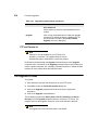
Table 5-1
Advanced User Interface
Network Properties Sheet, Continued
Function
Description
Advanced Network
The Advanced Network command button is enabled if
Specify an IP Address is selected or if a DHCP server was
detected on start-up or and Obtain an IP address from a
DHCP server is selected. Click on this command button to
invoke the Advanced Network Settings dialog box:
Enable DNS
Use the controls in this group to set domain, primary, and
secondary IP addresses for DNS. The default for the group is
disabled (Enable DNS not checked).
Enable WINS
Use the controls in this group to set the primary and secondary
IP addresses of a WINS server. The default for the group is
disabled (Enable WINS not checked).
6
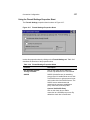
Web Browser
The Web properties (Figure 6-1) sheet lets you configure the Internet Explorer
browser.
Note
System time should be set accurately for cookies to
work properly for some Web pages. Use of a time
server is preferred. See “SNTP Client” in External
Devices for information about synchronizing system
time to a time server.
Using the Web Properties Sheet
To invoke this properties sheet:
1. Press F2 to invoke the Terminal Properties dialog box.
2. Click on the Web tab.
48
Advanced User Interface
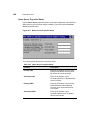
Figure 6-1 Web Properties Sheet
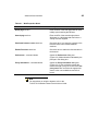
Table 6-1 discusses the functions of the Web properties sheet.
49
Advanced User Interface
Table 6-1
Web Properties Sheet
Function
Description
Home page text box
Enter the URL of the Web page that will open
initially upon launching the Browser.
Search page text box
Enter the URL of the search engine home
Web page or a Web page that has links to a
variety of search engines.
Persistent browser cache check box
Check this box if you want the contents of the
browser cache to be retained between
sessions.
Enable Favorites check box
Check this box to enable the favorites table in
the browser.
Preferences... command button
Opens the Preferences dialog box
(Figure 6-2). Make selections indicated by the
prompts in this dialog box.
Proxy Information... command button
Opens the Proxy Information dialog box
(Figure 6-3). If your terminal accesses the
Internet through a proxy server check the Use
proxy server box and make the appropriate
entries in the now-enabled text and check
boxes.
Note
For instructions on using the browser, refer to the
T1000/T1010 Windows-based Terminal Users Guide.
50
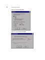
Advanced User Interface
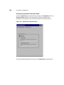
Figure 6-2 Preferences Dialog Box
Figure 6-3 Proxy Information Dialog Box
7
Additional Terminal Applications
The Apps properties sheet contains functions for ICA, RDP, DHCP, and SNMP
management options. See Figure 7-1.
Using the Apps Properties Sheet
Figure 7-1 shows this properties sheet. To invoke the Apps properties sheet:
1. Press F2 to invoke the Terminal Properties dialog box.
2. Click on the Apps tab in the Terminal Properties dialog box.
Table 7-1 describes the functions of the Apps properties sheet.
52
Advanced User Interface
Figure 7-1 Apps Properties Sheet)
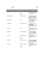
Table 7-1
Apps Properties Sheet
Function
Description
Global Settings
Group box used to manage ICA sessions.
ICA Client Settings
Click on the ICA Client Settings command button in
the Global Settings group box. See “ICA Client
Settings” in the Advanced User Interface section for
details about ICA client settings.
53
Advanced User Interface
Table 7-1
Apps Properties Sheet, Continued
Function
Description
SNMP Update
Enable
Check this box to enable terminal firmware updates
through SNMP.
SNMP Network...
Use this command button to invoke the SNMP
Network Administration dialog box. See “SNMP
Firmware Upgrades” in Firmware Upgrades for details
about this dialog box.
DHCP Automatic
Update Enable
Check this box to enable automatic firmware upgrades.
See “DHCP Firmware Upgrades” in Firmware
Upgrades for details.
Change DHCP
Option...
Use this command button to invoke the Change DHCP
Option IDs dialog box. See “DHCP Firmware
Upgrades” in Firmware Upgrades for details.
Port Lock
Click on the Port Lock command button to invoke the
Port Lock dialog box:
Use the list of check boxes in the dialog box to select
which ports you want to lock (enable). The default is all
boxes checked.
RDP Encryption
Enable
Click this check box to check and enable RDP
encryption. By default this function is enabled.
Caution
If your WTS server does not support encryption,
this function must be disabled.
8
ICA Client Settings
ICA client settings are handled in the Global ICA Client Settings dialog box. This
dialog box is invoked through the Apps properties sheet found in the Terminal
Properties dialog box. See “Additional Terminal Applications” for detailed
information about the Apps properties sheet. Figure 8-1 shows the Global ICA
Settings dialog box.
Figure 8-1 Default Hotkeys Properties Sheet
Note
An ICA session must be running for these hotkeys to
function.
56
Advanced User Interface
Using the Global ICA Client Settings Dialog Box
To invoke the Global ICA Settings dialog box:
1. Press F2 to invoke the Terminal Properties dialog box.
2. Click on the Apps tab in the Terminal Properties dialog box.
3. Click on the ICA Client Settings command button in the Global Settings group
box.
There are five properties sheets associated with the Global ICA Client Settings
dialog box. A description of the functions of each sheet follows.
Setting the Default Hotkeys
Hotkeys can be used during ICA sessions to invoke various functions. Some
hotkeys control the behavior of ICA windows, while others emulate standard
Windows hotkeys. To set hotkeys, access the Default Hotkeys properties sheet. It
is the default properties sheet for the Global ICA Client Settings dialog box. The
following figure shows the Default Hotkeys properties sheet.
Use the pull-down scroll boxes on the Default Hotkey properties sheet to
customize default hotkey key sequences. The following table describes the
hotkeys.
Table 8-1
Default Hotkeys Properties Sheet
Function
Description
Status Dialog
This function displays ICA connection status.
Close Session
This function disconnects an ICA client from a server
and closes the client window on the local desktop.
When you use this hotkey, the open session continues
to run on the server. If you do not want to leave the
session running in a disconnected state, log off.
Esc
Functions as Esc (escape) key.
Ctrl+Alt+Del
This hotkey displays the Windows NT Security dialog
box.
Ctrl+Esc
•
On WinFrame servers, pressing this key sequence
displays the Remote Task List.
•
On MetaFrame servers, pressing this key sequence
displays the Windows NT Start menu.
57
Advanced User Interface
Table 8-1
Default Hotkeys Properties Sheet, Continued
Function
Description
Alt+Esc
This hotkey cycles the focus through the minimized
icons.
Alt+Tab
This hotkey cycles sequentially through applications
that are open. A window appears to display the
applications as you cycle through them.
Alt+Backtab
This hotkey cycles sequentially through applications
that are open in a session, but in the opposite direction.
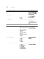
Setting Terminal Preferences
Use the Preferences properties sheet to change default settings. To invoke the
Preferences properties sheet:
1. Click on the ICA Client Settings command button on the Apps properties
sheet.
2. Click the Preferences tab.
The Preferences properties sheet displays. Figure 8-2 shows the Preferences
properties sheet.
Figure 8-2 Preferences Properties Sheet
The following table describes each function of the properties sheet.
58
Advanced User Interface
Table 8-2
Preferences Properties Sheet
Function
Description
Serial Number
This is the serial number of your ICA Client software.
This field is only necessary when you are using the ICA
Windows CE Client with a product such as WinFrame
Host/Terminal, which requires each client to have a
Citrix PC Client Pack serial number in order to connect
to the server. If a serial number is required, you must
enter it exactly as it appears on the serial number card.
The Serial Number field is not used by MetaFrame
servers.
Default Window
Colors
Two or three radio buttons are displayed. If the terminal
Color Palette (using the Display properties sheet in
the Terminal Properties dialog box) is 256 colors,
radio buttons for 16 or 256 colors are displayed. If
65536 is selected in the Color Palette, after restarting
the terminal an additional radio button, Thousands, is
displayed.
Note
The ICA server must be capable of supporting
16-bit color for the Thousands selection to
work. If not, the terminal will display only 256
(8-bit) colors when Thousands is selected.
When using a PPP connection, 16 color mode may
provide faster performance. If the window options
specified exceed the capabilities of the client hardware,
the maximum size and color depth supported by the
CE operating system are used.
59
Advanced User Interface
Table 8-2
Preferences Properties Sheet, Continued
Function
Description
Client Name
This text box allows you to change the client name of
your client device. The Citrix server uses the client
name to uniquely identify resources (such as mapped
printers) associated with a given client device. The
client name should be unique for each computer
running a copy of a Citrix ICA Client. If you do not use
unique client names, device mapping and application
publishing may not operate correctly. The default is
WBT<mac address>. The maximum length of the
client name is 15 characters.
Allow Automatic
Client Updates check
box
Use the Client Auto Update feature to store new
versions of Citrix ICA Clients. The ICA Client software
is stored in a client update database and downloaded
to the terminal when a user connects to the Citrix
server.
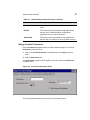
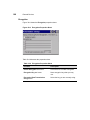
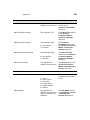
Setting the Server Location
Use the Server Location properties sheet to construct a list of ICA servers. To
invoke this properties sheet:
1. Click on the ICA Client Settings command button on the Apps properties
sheet.
2. Click the Server Location tab.
The Server Location properties sheet displays. The following figure shows this
sheet.
60
Advanced User Interface
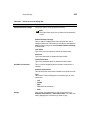
Figure 8-3 Server Location Properties Sheet
The following table describes each of the functions of this sheet.
Table 8-3
Server Location Properties Sheet
Function
Description
Add
Click on this command button to open the Add Server
Address dialog box. The server is added to the
selected server group. If you checked use HTTP
server location, you must enter the server address
and port to use.
Delete
Use this button to delete the name or IP address of a
server from the selected group.
use HTTP server
location
Check this box if your firewall restricts UDP
broadcasts. This option enables the client to retrieve a
list of all Citrix servers on the network and a list of all
published applications from a Citrix server that is
behind a firewall.
Default List
Use this button to recall the previous server list.
61
Advanced User Interface
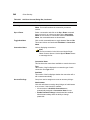
Table 8-3
Server Location Properties Sheet, Continued
Function
Description
Server Group
Use this drop-down list to select whether the servers
entered in the Address List field belong to your
Primary, first backup (Backup 1), or second backup
(Backup 2) group.
Rename Group
Opens the Rename Server Location Group dialog
box.
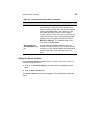
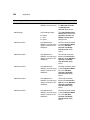
Setting Up a SOCKS Firewall
Use the Firewall Settings properties sheet to set up a SOCKS (Socket Secure)
firewall. To invoke this properties sheet:
1. Click on the ICA Client Settings command button on the Apps properties
sheet.
2. Click the Firewall Settings tab.
The properties sheet displays. The following figure shows this sheet.
Figure 8-4 Firewall Settings Properties Sheet
The following table describes each of the functions of this sheet.
62
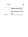
Advanced User Interface
Table 8-4
Firewall Settings Properties Sheet
Function
Description
Use Alternate Address Through
Firewalls
By default the box is not checked.
SOCKS
Use this group box to enable and
configure SOCKS protocol.
Connect Via SOCKS Proxy
Check this box to enable a SOCKS
proxy connection. SOCKS is a
protocol that sets up a proxy server
between a client and a server. This
proxy server then acts as a channel for
communication between the client and
server. By default the box is not
checked.
Address of Proxy to Use
Enter in this text box the address of
the proxy server. By default this box is
deactivated.
Port
Enter in this text box the port number.
By default this box is deactivated.
Advanced User Interface
63
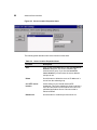
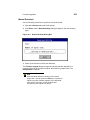
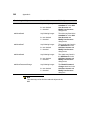
Setting Up a PNLite
PNLite is an ICA connection mode that enables the terminal to connect to
applications available on a Citrix server without having to configure connections for
each published application.
Note
Refer to “NFuse Server Configuration Requirements”
for an explanation of the differences between the
methods of accessing published applications via the
NFuse server and limitations on the NFuse server
application setup for use with Model T10x0 series
terminals.
Note
PNLite connections are not supported by failover (See
“Failover”).
To invoke this properties sheet:
1. Click on the ICA Client Settings command button on the Apps properties
sheet.
2. Click the PNLite tab.
The properties sheet displays. The following figure shows this sheet.
Figure 8-5 PNLite Properties Sheet
64
Advanced User Interface
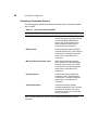
The following table describes each of the functions of this sheet.
Table 8-5
PNLite Properties Sheet
Function
Description
Enable PNLite
Check to enable the PNLite
application.
Server area
Enter the address and port number of
the NFuse server in the Address and
port of NFuse server text boxes.
User credentials area
Enter the requested information in the
User Name, Password, and Domain
text boxes. Check the Save password
box if you want the password retained
on the terminal.
Connection Configuration
14
15
16
17
18
19
20
21
22
23
24
25
Creating New Connections
ICA Connections
Dial-Up Connections
Dial-Up Dialing Properties and Configuration
Dial-Up TCP/IP Settings and Security
Dial-Up Scripts
RDP Connections
Terminal Emulation Connections
TCP/IP Telnet Configuration
Internet Explorer Connections
Editing ICA Connections
Editing RDP, Dial-Up, and Terminal Emulation Connections
9
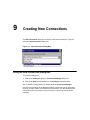
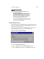
Creating New Connections
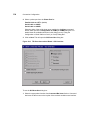
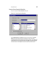
The New Connection dialog box is used to create new connections. Figure 9-1
shows the New Connection dialog box.
Figure 9-1 New Connection Dialog Box
Using the New Connection Dialog Box
To invoke the dialog box:
1. Click on the Configure tab in the Connection Manager dialog box.
2. Click on the Add command button on the Configure properties sheet.
See “Connection Configuration” for details about the Connection Manager.
Use the scroll list shown in the dialog box above to select the type of connection
protocol you want. When you choose from the list above, you are deciding which
connection protocol you want to use to connect to a server. Six selections are
available.
68
Connection Configuration
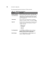
Choosing a Connection Protocol
The following table describes the differences between the connections available
with your WBT.
Table 9-1
New Connection Dialog Box
Connection Protocol
Description
Citrix ICA Client
ICA (Independent Computing
Architecture) protocol, which connects
to an ICA (Winframe/Metaframe)
server. See “ICA Connections” for
further instructions about how to
create this kind of connection.
Dial-Up Client
Connects using a modem and PPP
(Point-to-Point Protocol). See “Dial-Up
Connections” for further instructions
about how to create this kind of
connection.
Microsoft Remote Desktop Client
RDP (Remote Desktop Protocol),
which connects to a WTS (Windows
Terminal Server) server. See “RDP
Connections” for further instructions
about how to create this kind of
connection.
Internet Explorer
Local browser (Internet Explorer)
connection. See “Internet Explorer
Connections” for further instructions
about how to create this kind of
connection.
Terminal Emulation
Connects to multiple terminal
emulation applications. See “Terminal
Emulation Connections” for further
instructions about how to create this
kind of connection.
Once you have made your selection, click on OK to proceed with creating a
connection.
Connection Configuration
69
Note
A Use Printer Configuration Utility check box is
encountered in two places:
(1) Connection Manager (Select an ICA Connection) |
Edit | Edit Connection Details | Options tab, and
(2) Connection Manager | Add | (Select Citrix ICA
Client | Wizard leading to Printing, Compression,
Cache, Encryption and Sound dialog box.
The box is checked by default. Uncheck the box if you
desire to use the standard Windows printer setup. Also
un-check the box for CDS printing.
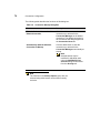
Using the Startup Function
Your terminal can be set to automatically connect to a server when you turn your
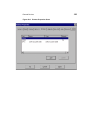
terminal on. This function is set using the Connection Startup dialog box. The
following figure shows this dialog box.
Click on one of the two radio buttons in the Startup Options group box (in the
Connection Startup dialog box above) to select a start-up option:
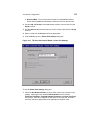
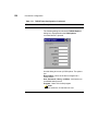
Figure 9-2 Connection Startup Dialog Box
To invoke the Connection Startup dialog box:
1. Click on the Configure tab in the Connection Manager dialog box.
2. Click on the Startup command button on the Configure properties sheet.
70
Connection Configuration
The following table describes the functions of this dialog box.
Table 9-2
Connection Startup Dialog Box
Function
Description
Make the Selected Connection Your
Default Connection
Click this radio button to use the
connection you selected in the
Connection Manager as the default
connection. The default connection is
the connection that always appears in
the Connection Name list.
Automatically Start the Selected
Connection at Startup
Click this radio button to start the
connection you selected in the
Connection Manager automatically at
startup.
Note
Autostart status may be
modified for individual users
using the Add/Modify User
Account dialog box accessed
from the Security tab.
Note
The functions in the Startup Options group box are
selected using radio buttons and are thus mutually
exclusive.
10 ICA Connections
Use the Specify Connection Type dialog box to start configuring an ICA
connection. The ICA protocol connects you to a server running Citrix WinFrame or
MetaFrame.
Using the ICA Connections Wizard
When the New Connection dialog box is open (see “Creating New Connections”):
1. Use the drop-down scroll list to select Citrix ICA Client.
2. Click on OK.
Figure 10-1 shows the Specify Connection Type dialog box. This is the first dialog
box that appears in the series.
•
Network Connection
•
•
Click on this radio button to create a network ICA connection. This type of
connection requires a direct line to the network, such as 10Base-T. See
“Network Connections.”
Dial-In Connection
•
Click on this radio button to create a serial ICA connection. This type of
connection is made using a modem or a direct connection. See “Dial-Up
Connections.”
72
Connection Configuration
Figure 10-1 Specify Connection Type Dialog Box
Network Connections
Select Network Connection, then click on the Next button. A Citrix search
message displays:
Figure 10-2 Citrix Search Message
If the connection is found, the following sequence of dialog boxes displays. Use
them to set up your network ICA connection.
Connection Configuration
Figure 10-3 Select a Citrix Server or Published Application Dialog Box
To use the Select a Server or Published Application dialog box:
1. Click on either Citrix Server or Published Application.
2. Select a server or an application from the drop-down scroll list, or type the
information in the text entry box.
Note
The Refresh command button refreshes the
drop-down scroll list.
Note
The Server Location command button invokes the
Server Location dialog box. The server in Server
Location will act as a master browser for creation of
the Address list. See Figure 10-4.
73
74
Connection Configuration
Figure 10-4 Server Location Dialog Box
3. If you want to add a server name or IP address, click on the Add command
button to invoke the Add Server Address dialog box.
Figure 10-5 Add Server Address Dialog Box
4. Enter the name or IP address of the Citrix server. Click on OK in this dialog box
and then click on OK in the Server Location dialog box.
5. Click on Next.
Connection Configuration
Figure 10-6 Select a Title for the ICA Connection Dialog Box
Enter a connection in the text box in the Select a Title for the ICA Connection
dialog box, then click on Finish.
Figure 10-7 Specify an Application Dialog Box
To use the Specify an Application dialog box:
1. Enter the command line and directory of the application that you intend to
invoke.
2. Click on Next.
75
76
Connection Configuration
Figure 10-8 Specify Logon Information Dialog Box
To use the Specify Logon Information dialog box:
1. If needed, enter a user name, a password, and a domain for connecting to an
application.
2. Click on Next.
Figure 10-9 Select Window Options Dialog Box
Connection Configuration
77
To use the Select Window Options dialog box:
1. Click on the desired number of colors to display, 16, 256, (or Thousands).
Two or three radio buttons are displayed depending on the pallette selected. If
the terminal Color Palette (Display properties sheet in Terminal Properties
dialog box) is 256 colors, radio buttons for 16 or 256 colors are displayed. If
65536 is selected in the Color Palette, after restarting the terminal an additional
radio button, Thousands, is displayed in this dialog box.
Note
The ICA server must be capable of supporting 16-bit color for the
Thousands selection to work. If not, the terminal will display only 256 (8-bit)
colors when Thousands is selected.
2. Click on Next.
Figure 10-10
Compression, Encryption and Sound Dialog Box
To use the Compression, Encryption and Sound dialog box:
1. Enable or disable the following functions:
a. Use Printer Configuration Utility check box - See “Local Printers.”
a. Compress Data Stream check box - Applies compression.
b. Enable Sound check box and Sound Quality check box - High, Medium,
and Low sound quality selectable with this function.
c. SpeedScreen drop-down menu - Allows selection of Off (default), On, or
Auto for possible improvement of screen display performance.
78
Connection Configuration
SpeedScreen is a latency reduction feature that enhances the user’s
experience on slower network connections. It echos local text to accelerate
display of input text on the terminal and provides visual feedback for mouse
clicks to show that the user’s input is being processed.
d. Encryption Level - Drop-down menu allows selection of the encryption
level:
Basic (default)
RC5 (128 bit - Login Only)
RC5 (40 bit)
RC5 (56 bit)
RC5 (128 bit)
2. Click on Next.
Figure 10-11 Firewall Settings Dialog Box
1. Enable or disable the following functions:
a. Use Alternate Address Through Firewalls
b. SOCKS
c. Connect Via SOCKS Proxy
d. Address of Proxy to Use
e. Port
2. Click on Finish.
Connection Configuration
79
Dial-In Connection
Note
This section applies only to the SE Model terminals.
Choose Dial-In Connection, then click on the Next button. The following sequence
of dialog boxes displays. Use them to set up your dial-in ICA connection.
Figure 10-12
Dial-In Devices Dialog Box
To use the Dial-In Devices dialog box:
1. From the Dial-In Device drop-down scroll list, select one of the following:
a. A modem connection such as Hayes Compatible on Com1.
b. A serial connection such as Serial Cable on Com1.
2. Enter the area code, the phone number, and the country code in the appropriate
fields.
3. Click on Configure to use the Device Properties dialog box. (See “Using the
Device Properties Dialog box” for information on the Device Properties dialog
box).
4. See Figure 10-6 through Figure 10-11 and the related text for information about
the remainder of the dialog boxes in this sequence.
When you are finished with the configuration, the Connection Manager displays,
listing your new ICA connection.
11
Dial-Up Connections
Use the Dial-Up Configuration Wizard to configure a dial-up connection. Dial-up
connections use a modem and PPP to connect to a server.
Using the Dial-Up Configuration Wizard
From the New Connection dialog box (see “Creating New Connections”):
1. Use the drop-down scroll list to select Dial-Up Client.
2. Click on OK.
Following are the three dialog boxes that display in succession during a dial-up
configuration process. When you are finished with the configuration, the new
connection will be added to the Connection Name list in the Connection
Manager. See Figure 11-1 to view the first dialog box of the wizard.
82
Connection Configuration
Figure 11-1
Dial-Up Configuration Wizard 1
To use the first dialog box:
1. Enter a name for your dial-up connection (a maximum of 20 characters but not
<>()[]/\.*?:",| ).
2. Click on Next.
Connection Configuration
83
Figure 11-2 Dial-Up Configuration Wizard 2
To use the second dialog box of the wizard:
1. Select from the Serial Port drop-down scroll list one of the following:
a. A modem connection such as Hayes Compatible on Com1.
b. A cable connection (serial connection) such as Serial Cable on Com1.
2. Enter your information in the pertinent fields. Country Code and Area Code will
activate if Use Country Code and Area Code is enabled.
3. Click on the Dialing Properties command button to open the Dialing
Properties dialog box. See “Using the Dialing Properties Dialog Box” for
details about this dialog box.
4. Click on the Configure command button to open the Device Properties dialog
box. See “Using the Device Properties Dialog Box” for details about this
dialog box.
84
Connection Configuration
5. Click on the TCP/IP Settings command button to open the TCP/IP Settings
dialog box. See “Dial-Up TCP/IP Settings and Security” for details about this
dialog box.
6. Click on the Security command button to open the Security Settings dialog
box. See “Dial-Up TCP/IP Settings and Security” for details about this dialog
box.
7. Check the Enable RAS Script check box, and click on the Script command
button to open the RAS Script dialog box. See “Dial-Up Scripts” for details
about this dialog box.
8. Click on Next. This opens the dialog box shown in Figure 11-3.
To use the dialog box:
1. Enter your information in the pertinent fields. If you do not know the information,
contact your system administrator.
2. Click on Finish.
The Connection Manager displays, listing your new dial-up connection.
Connection Configuration
Figure 11-3 Dial-Up Configuration Wizard 3
85
12 Dial-Up Dialing Properties and
Configuration
The following sections provide information about some of the elements of the
Dial-Up Configuration Wizard. This chapter covers dialing properties and device
properties. Dialing properties are set using the Dialing Properties dialog box
(Figure 12-1). Device properties are set using the Device Properties dialog box
(Figure 12-2).
Note
See “Null Modem Cable Pin Assignments” for a
suggested null modem cable for use with your terminal.
Using the Dialing Properties Dialog Box
Use the Dialing Properties dialog box to set the dialing properties for your dial-up
connection. See “Dial-Up Connections” to find out how to invoke this dialog box.
88
Connection Configuration
Figure 12-1 Dialing Properties Dialog Box
The following table discusses the functions of the dialog box.
89
Connection Configuration
Table 12-1 Dialing Properties Dialog Box
Function
Description
Local Settings
Set local dialing locale and dialing type in this group
box.
Local Area Code
Enter the local area code that you want to use.
Local Country Code
Enter the local country code of the country to which
you are dialing. The default for this field is 1.
Note
Refer to a phone directory for country codes.
Disable Call Waiting by Dialing:
1. Click on the check box.
2. Select from the drop-down scroll list one of the
following:
•
*70, (default)
•
70#,
•
1170,
Tone Dialing
Click on this radio button to enable tone dialing. Tone
Dialing is the default.
Pulse Dialing
Click on this radio button to enable pulse dialing.
90
Connection Configuration
Table 12-1 Dialing Properties Dialog Box, Continued
Function
Description
Dialing Patterns
Use this group box to set your modem’s dialing
patterns.
Local Calls Dialing
Enter the local call dialing pattern. The default is 9,G.
Local Long Distance Calls Dialing
Enter the long distance call dialing pattern. The default
is 9,1FG.
International Calls Dialing
Enter the international call dialing pattern. The default
is 9,011,EFG.
Note
An explanation of the lettering scheme for
dialing patterns is located below the function
International Calls Dialing.
Using the Device Properties Dialog Box
Use the Device Properties dialog box to configure a device (modem) for a dial-up
connection. See “Dial-Up Connections” to find out how to invoke this dialog box.
Figure 12-2 Device Properties Dialog Box
91
Connection Configuration
The Device Properties dialog box contains two properties sheets:
•
Port Settings
•
Call Options
The following sections discuss these properties sheets.
Port Settings
See Figure 12-2 to view the Port Settings properties sheet. It is the default of the
Device Properties dialog box. The following table discusses the functions of this
properties sheet.
Table 12-2 Port Settings Properties Sheet
Function
Description
Manual Dial
Click on this check box to set up for manual dialing.
Terminals
Use this group box to record terminal windowing
information:
Connection
Preferences
•
Use Terminal Window Before Dialing
•
Use Terminal Window After Dialing
Use this group box to set modem connection
parameters.
92
Connection Configuration
Call Options
Click on the Call Options tab to invoke the Call Options properties sheet.
Figure 12-3 Call Options Properties Sheet
The following table discusses the functions of this properties sheet.
Table 12-3 Call Options Properties Sheet
Function
Description
Call Setup
Use this group box to configure the following call
parameters:
Cancel the Call if Not Connected Within
1. Enter in this field the number of seconds to wait
before a call is canceled. The default is 120 with the
function enabled.
2. Click the check box to enable the function.
Wait for Dial Tone Before Dialing
Click on the check box to enable the function. By
default this function is enabled.
Wait for Credit Card Tone
Enter in the field the period (in seconds) of time to wait.
The default is 0.
Extra Settings
Use this field for special modem commands. See
“Modem AT Commands” in Getting Help for more
details.
13 Dial-Up TCP/IP Settings and
Security
The following sections provide information about some of the elements of the
Dial-Up Configuration Wizard. This chapter covers TCP/IP settings and dial-up
security.
Using the TCP/IP Settings Dialog Box
Click on the TCP/IP Settings command button in the second dialog box of the
Dial-Up Configuration Wizard to set TCP/IP dial-up settings. When this command
button is pressed, the TCP/IP Settings dialog box displays. Figure 13-1 shows this
dialog box.
Figure 13-1 TCP/IP Settings Dialog Box
94
Connection Configuration
The following table discusses the functions in this dialog box.
Table 13-1 TCP/IP Settings Dialog Box
Function
Description
Use Software Compression
Click on this check box to enable this
function. By default, this function is
activated and enabled.
Use IP Header Compression
Click on this check box to enable Use
IP Header Compression. By default,
this function is activated and enabled.
Use SLIP
Click on this check box to enable this
function. SLIP is Serial Line Internet
Protocol. By default, this function is not
enabled.
Use Assigned IP Address
Click here to activate this text box. By
default, the text entry box is not
activated.
Use Server-Assigned IP Addresses
Click here to disable server-assigned
addresses and to activate the text
entry boxes for typing-in addresses.
By default, the check box is checked
and the text entry boxes are not
activated.
Use Default Gateway on Remote
Network
Click on this check box to enable this
function. By default, the function is
activated and enabled.
Using the Security Settings Dialog Box
Click on the Security... command button in the second dialog box of the
Dial-Up Configuration Wizard to configure dial-up security. When this command
button is pressed, the Security Settings dialog box displays. Figure 13-2 shows
this dialog box.
95
Connection Configuration
Figure 13-2 Security Settings Dialog Box
The following table discusses the functions in this dialog box.
Table 13-2 Security Settings Dialog Box
Function
Description
Accept Any Authentication
Including Clear Text (default)
Click on this radio button to set your
terminal to accept any authentication
including clear text. Authentication
determines whether a request
originated from the correct user or
application.
Accept Only Encrypted
Authentication
Click on this radio button to set your
terminal to accept only encrypted
authentication. Encryption is a method
of “hiding” data that is transmitted
across a network.
Accept Only Microsoft Encrypted
Authentication
Click on this radio button to set your
terminal to accept only Microsoft
encrypted authentication.
14 Dial-Up Scripts
Dial-up RAS (Remote Access Services) scripts are enabled from the Dial-Up
Configuration Wizard (see “Dial-Up Connections”). RAS facilitates PPP
communications between the terminal (based on Windows CE) and other
non-Windows operating systems.
Using the Dial-Up Scripts Dialog Boxes
Dial-up scripts dialog boxes are accessed by checking the Enable RAS script box
and pressing the Script command button in the second panel of the Dial-Up
Configuration Wizard. These dialog boxes automate actions that otherwise would
be performed in text mode after dialing.
The Script Name dialog box (Figure 14-1) enables you to create a script under a
new name, edit an existing script, or delete an existing script. Press the New button
to open the New Script Name dialog box (Figure 14-2). Type the script name and
press OK. This opens the RAS Script dialog box. You may also open the RAS
Script dialog box to edit an existing script by selecting the script and pressing Edit.
Table 14-1 describes the RAS Script dialog box. To delete as script, select it and
press Delete.
98
Connection Configuration
Figure 14-1 Script Name Dialog Box
Figure 14-2 New Script Name Dialog Box
99
Connection Configuration
Figure 14-3 RAS Script Dialog Box
Table 14-1 RAS Script Dialog Box
Function
Description
Script Name text box and Change
button
The text box displays the name of the
currently selected script. You may
change the selection by clicking on the
Change button to open the Script
Name dialog box. Select another script
and click OK.
Script area:
Text Box
Lists the script input/output strings:
•
Wait For - Displays strings
received from the host.
•
Respond With - Displays what the
terminal sends in response to the
Wait For string.
100
Connection Configuration
Table 14-1 RAS Script Dialog Box, Continued
Function
Description
New and Edit buttons
New and Edit open the Edit Script
Line dialog box (see Figure 14-4). Use
this dialog box to create a new line in
the script or edit an existing (selected)
line. The specific scripts are unique to
each target system.
Up, Down, Delete buttons
Use Up and Down to move a selected
line in the script up or down in the list.
To delete a line, select it and press
Delete. You will be prompted to
confirm deletion of the line.
Figure 14-4 Edit Script Line Dialog Box
15 RDP Connections
Use the WTS Connection Wizard to configure an RDP connection. RDP connects
to a server running Microsoft WTS (Windows Terminal Server).
Using the WTS Connection Wizard
When the New Connection dialog box is open (see “Creating New Connections”):
1. Use the drop-down scroll list to select Microsoft Remote Desktop Client.
2. Click on OK.
Following are the four dialog boxes that display in succession during the
configuration process. When you are finished with the wizard, the new connection
will be added to the Connection Name list in the Connection Manager.
Figure 15-1 shows the first dialog box of this wizard.
102
Connection Configuration
Figure 15-1 WTS Connection Wizard 1
To use the first dialog box:
1. Enter a name for your dial-up connection in Name.
2. Enter the name or IP address of the server in Server.
3. Check the Low Speed Connection check box if appropriate.
4. Click on Next.
Connection Configuration
Figure 15-2 WTS Connection Wizard 2
To use the second dialog box:
1. Check the Automatic Logon check box if appropriate.
2. Enter a user name, password, and a domain to complete the information.
3. Click on Next.
103
104
Connection Configuration
Figure 15-3 WTS Connection Wizard 3
To use the third dialog box in the wizard:
1. Click on either the Desktop or Application File Name radio buttons.
2. If you clicked on Desktop, click on Next.
3. If you clicked on Application File Name:
a. Enter the name of the application.
b. Enter the name of the directory where it resides.
c. Click on Next.
Connection Configuration
105
Figure 15-4 WTS Connection Wizard 4
To use the fourth dialog box, click on Finish. The Connection Manager displays,
listing your new RDP connection.
16 Terminal Emulation Connections
Using the TE Client Connection Wizard
When the New Connection dialog box is open (see “Creating New Connections”):
1. Use the drop-down scroll list to select Terminal Emulation.
2. Click on OK.
Following are the three dialog boxes of this wizard. When you are finished
configuring a connection, the new connection will be added to the Connection
Name list in the Connection Manager. Figure 16-1 shows the first dialog box of
this wizard.
108
Connection Configuration
Figure 16-1 TE Client Connection Wizard - Connection Information
To use the Connection Information dialog box:
1. Enter the connection name in Connection Name text box.
2. Select the emulation type in the Emulation scroll list.
3. Select the terminal type from the VT TerminalID scroll list. Table 16-1 describes
the available functions in the VT TerminalID scroll list.
4. Click on Next to continue to the Host Information dialog box (Figure 16-3).
Note
Depending on the emulation chosen, the appearance
of the TE Client Connection Wizard -Connection
Information dialog box changes, to provide for
selecting appropriate parameters for that emulation.
These are described in Table 16-1.
109
Connection Configuration
Table 16-1 Terminal Emulation and Terminal Type
Terminal Emulation
Terminal Type
Select Emulation:
VT52, VT100, VT400 7-Bit (default),
or VT400 8-Bit
Then select from VT TerminalID:
Select Emulation:
vt100, vt101, vt102, vt125, vt220,
vt240, vt320, vt340, vt420 (default),
vt131, or vt132
The function is deactivated.
ANSI BBS, SCO Console, WY50,
WY50+, TVI910, TVI920, TVI925,
TVI955, ADDS A2, HZ1500, or WY60
Select Emulation:
Then select from IBM3151 Model:
11 (default), 31
IBM3151
Select Emulation:
1. Then select from IBM 3270 Model:
IBM3270
3278-2, 3278-3, 3278-4, 3278-5,
3278-2-E (default), 3278-3-E,
3278-4-E, 3278-5-E, 3279-2, 3279-3,
3279-4, 3279-5, or 3287-1
2. Check the Right Ctrl Acts as
Enter Key or the Left Ctrl Acts as
Reset Key check boxes if you want
these functions enabled for 3270
emulation.
Select Emulation:
IBM5250
1. Select from IBM 5250 Model:
5291-1, 5292-2, 5251-11, 3179-2
(default), 3196-A1, 3180-2,
3477-FC, 3477-FG, 3486-BA,
3487-HA, 3487-HC, or 3812-1
2. Check the IBM5250 Monochrome,
Left Ctrl Acts as Reset Key, Right
Ctrl Acts as Enter Key, or the
Carriage Return acts as Enter
Key check boxes if you want these
functions enabled for 5250
emulation.
110
Connection Configuration
Table 16-1 Terminal Emulation and Terminal Type, Continued
Terminal Emulation
Terminal Type
Select Emulation:
Then select from HP Model:
2392A, 70092 (default), 2622A
HP70092
International Settings
Opens the International Settings
dialog box (see Figure 16-2). The
particular controls and selections that
appear in this dialog box depends on
the terminal emulation selected. Make
keyboard, character set, and other
selections in this dialog box as
applicable.
Figure 16-2 International Settings Dialog Box
Connection Configuration
111
Figure 16-3 TE Client Connection Wizard - Host Information
To use the Host Information dialog box:
1. Click on TCP/IP, Modem, or Serial:
2. If you clicked on TCP/IP:
a. Enter the host name or IP address in Host Name.
b. Use the Advanced command button if appropriate. (See “Using the TCP/IP
Telnet Configuration Dialog Box” for information about the Advanced
command button).
c. Click on Next. The Automate Login Process dialog box displays. See
Figure 16-4 and proceed with these instructions.
3. If you clicked on Modem:
a. Select a configuration from Configuration Name.
b. Use the Configure command button if appropriate. (See “Using the Modem
Settings Dialog Box” for information about the Configure command button).
112
Connection Configuration
c. Click on Next. The Automate Login Process dialog box displays. See
Figure 16-4 and proceed with these instructions.
4. If you clicked on Serial:
a. Make a selection from Connect To.
b. Use the Configure command button if appropriate. (See “Using the
Configuration of Serial Cable on Com1 (or Com2) Dialog Box” for information
about the Configure command button).
c. Click on Next. The Automate Login Process dialog box displays. See
Figure 16-4 and proceed with these instructions.
Figure 16-4 TE Client Connection Wizard - Automate Login Process
To use the Automate Login Process dialog box:
1. Fill in the Parameters group box as appropriate using the following functions:
a. Set Initiation String - Set the scripts initiation string.
b. Wait For - Act on an selected event in the Act On list such as login.
Connection Configuration
113
c. Respond With - The scroll list receives input from the Insert command
button and the Insert command button inserts an item from the scroll list.
2. Use the Add and Remove command buttons to add or remove lines from the
Script scroll list.
3. Use the Remove All command button to remove all the scripts from the Script
scroll list.
4. Select a script from the Script scroll list as appropriate.
5. Click on Next to open the Printer Port Settings dialog box.
Figure 16-5 TE Client Connection Wizard - Printer Port Settings
To use the Printer Port Settings dialog box:
1. Check the Use Network Printer box if you want to print from a printer in your
network. Checking this box enables LPD Hostname text box and the
FormFeed Terminator, Translate National Characters, and Auto Line Feed
check boxes. Enter the IP address or DNS name of the LPD host, and make
check box selections appropriate to the application and printer used.
114
Connection Configuration
2. Select a printer port from the Printer Port list:
Parallel Cable on LPT1: (default)
Serial Cable on COM1:
Serial Cable on COM2:
Selecting either of the serial printer ports enables the Configure command
button, which opens the Configuration of COM1 (or COM2) dialog box. For
details about the available selections in this dialog box see “Using the
Configuration of Serial Cable on Com1 (or Com2) Dialog Box” .
3. Click on Next. This will open the GUI Overrides dialog box.
Figure 16-6 TE Client Connection Wizard - GUI Overrides
To use the GUI Overrides dialog box:
1. Select the appropriate functions from Command Bar Items list box. Command
bar items are the menus on the top bar of the terminal emulation user interface.
Connection Configuration
115
Note
After choosing Command Bar Items as an
administrator, the terminal must be logged-in as a user
to see the effect on the terminal session. Terminal
security must be enabled.
2. Select the appropriate function from Action on Host Close. These functions
are actions that will take place when the terminal emulation session is closed.
3. Click on the Disable Status Bar or No Connection Warning on Close check
boxes as appropriate. Disable Status Bar deactivates the status bar in a
terminal emulation session and No Connection Warning on Close deactivates
any kind of warning before a session closes.
Click on Finish. The Connection Manager displays, listing your new terminal
emulation connection.
17 TCP/IP Telnet Configuration
Note
The information in this chapter applies to the terminal
emulation connection only.
Using the TCP/IP Telnet Configuration Dialog Box
The Advanced command button on the TE Client Connection Wizard - Host
Information dialog box invokes the TCP/IP Telnet Configuration dialog box.
Figure 17-1 shows this dialog box.
Figure 17-1 TCP/IP Telnet Configuration Dialog Box
118
Connection Configuration
The following table discusses the functions of a Telnet connection.
Table 17-1 TCP/IP Telnet Configuration
Function
Description
Host Port Number
Enter the Telnet host port number. The default is 23.
Local Port Number
Implemented to allow connection to Misys hosts. This
allows the host to communicate back to the emulator
on a different port than the emulator uses to talk to the
host. The default is 0.
Telnet Name
Enter the Telnet virtual terminal name. The default
depends on emulation (VT400, 7-bit, default is vt420).
Suppress
Use the functions of this group box as needed (controls
in this area become active depending on the type of
emulation selected):
•
Echo (default)
•
3270 Regime
•
TN3270E
•
TN5250E
Force Negotiation
Use the Binary and EOR drop-down scroll lists to
configure negotiation parameters. The default for
Binary is No and the default for EOR is No.
Break Settings
Use the TM with Break and CR with Break check
boxes to configure break settings.
119
Connection Configuration
Table 17-1 TCP/IP Telnet Configuration, Continued
Function
Description
The following image shows the TN3270 Options
dialog box, displayed when the 3270 Options
command button is pressed.
Use this dialog box to set up 3270 options:
3270 LU Device Name - This group box is used to
identify the LU (Logical Unit).
TN3270E Options - This group box is used to set
TN3270E options. The options are:
Bind - BIND (Berkeley Internet Name Domain) DNS
server
Responses - System response
SysReq - System requests
Note
Associate, LU1 Printer, and LU3 Printer are
deactivated.
120
Connection Configuration
Table 17-1 TCP/IP Telnet Configuration, Continued
Function
Description
•
TN5250 Options
The following dialog box shows the TN5250 Options
dialog box, displayed when the 5250 Options
command button is pressed.
Use this dialog box to set up 5250 options. The options
are:
Device Name - Name of the device assigned to a
Telnet session.
User, Password, Library, and Menu - Initial entries on
a standard startup screen.
Program - Name of the initial program.
Note
All entries are 10 characters or less.
121
Connection Configuration
Using the Modem Settings Dialog Box
The Configure command button invokes the Modem Settings dialog box.
Figure 17-2 shows this dialog box.
Figure 17-2 Modem Settings DIalog Box
The following table discusses the available modem settings.
Table 17-2 Modem Settings Dialog Box
Function
Description
Configuration Name
Enter the name of your configuration.
Select a Modem
Select a modem from the drop-down scroll list.
Configure
Opens the Device Properties dialog box. See “Using
the Device Properties Dialog Box” for information
about this function.
Area Code
Enter the area code in this text box.
Telephone Number
Enter the telephone number in this text box.
Country Code
Enter the country code in this text box.
Dialing From:
This field automatically lists where you are calling from.
Dialing Properties
SSee “Dial-Up Dialing Properties and Configuration”
for information about this function.
Force Long Distance
Check this box to force long distance calling.
Force Local
Check this box to force local calling.
122
Connection Configuration
Using the Configuration of Serial Cable on Com1 (or Com2)
Dialog Box
This dialog box opens when the Configure command button is pressed for a serial
connection type selection. Figure 17-3 shows this dialog box.
Figure 17-3 Configuration of Serial Cable on Com1 (or Com2) Dialog Box
123
Connection Configuration
The following table discusses this dialog box.
Table 17-3 Configuration of Serial Cable on Com1 (or Com2) Dialog Box
Function
Description
Configuration of a
Serial Cable on
Com1 or Com2
Use these functions to configure a serial cable:
•
Baud Rate
•
Parity
•
Flow Control
•
Data Bits
•
Stop Bits
•
Transmit Limit
Each is presented as a drop-down scroll list. Click on
the upper-right down arrow to display the list and select
a value. The defaults are listed (consecutive to the
Function list to the left) as follows:
Local Echo
•
9600
•
None
•
Input
•
8
•
1
•
Unlimited
Check this check box if you want transmitted
characters to appear on the dialup terminal window.
Not needed if the destination machine has remote
echo turned on.
18 Internet Explorer Connections
Note
Internet Explorer requires that a minimum of 16 MB of
flash memory and 32 MB of RAM is installed on the
terminal. The installed memory is listed on the
Terminal Properties window SysInfo and General
tabs.
When the New Connection dialog box is open (see “Creating New Connections”):
1. Use the drop-down scroll list to select Internet Explorer.
2. Click on OK.
This opens the Internet Explorer Setup dialog box (Figure 18-1).
3. Type a Title for the connection.
4. Enter the URLs of your choice for the Start and Search pages.
5. If this server is to be included in failover, check the Allow to ping Start Site
check box.
Note
To help decide whether you should check this box, refer to the chapter on
“Failover” in this section.
6. Click on OK.
126
Connection Configuration
Figure 18-1 Internet Explorer Setup Dialog Box
Note
If the connection is to an NFuse server that provides
ICA links within a Web page to allow ICA sessions to
be launched from within a browser window, refer to
“NFuse Server Configuration Requirements” for
information concerning limitations on the NFuse server
application setup for use with Model T10x0 series
terminals.
19 Editing ICA Connections
The Connection Manager lets you edit individual ICA connection parameters. It is
done through the Edit Connection Details dialog box. The following figure shows
this dialog box.
Figure 19-1 Edit Connection Details Dialog Box
128
Connection Configuration
Using the Edit Connection Details Dialog Box
The Edit Connection Properties dialog box consists of seven properties sheets.
Use any or all of these properties sheets to edit connection parameters. To invoke
the dialog box:
1. Click on the Configure tab in the Connection Manager dialog box.
2. Click to select an ICA connection from the Connections Name list.
3. Click on the Edit command button on the Configure properties sheet.
Using the Server Properties Sheet
The Server properties sheet is displayed by default for the dialog box. Table 19-1
describes the functions of the Server properties sheet.
Table 19-1 Server Properties Sheet
Function
Description
Select a Citrix Server From the List
or Type in a server Name
Click on:
Server Location
•
Citrix Server
Enable this radio button to connect
to a Citrix server.
•
Published Application
Enable this radio button to connect
directly to an application.
Click on this command button to
invoke the Server Location Dialog
Box.
Server Group
Select from a scroll list:
•
Primary
•
Backup 1
•
Backup 2
Primary is the default.
Add
Click on this command button to add a
server to the list.
129
Connection Configuration
Table 19-1 Server Properties Sheet, Continued
Function
Description
Delete
Click on this command button to delete
a server from the list:
1. Select a server from the list.
2. Click on the Delete command
button.
Move Up
Click on this command button to move
a server up the list:
1. Select a server to move up.
2. Click on the Move Up command
button.
Move Down
Click on this command button to move
a server down the list:
1. Select a server to move down.
2. Click on the Move Down command
button.
Address
Lists the servers.
Default List
Lists the default servers.
Network Protocol
Lists the network protocol used by the
server.
130
Connection Configuration
Using the Application Properties Sheet
The Application properties sheet is shown in Figure 19-2.
Figure 19-2 Application Properties Sheet
Invoke the properties sheet by clicking on the Application tab. Table 19-2
describes the functions of the properties sheet.
Table 19-2 Application Properties Sheet
Function
Description
Command Line
Enter the command line used to
invoke the application.
Working Directory
Enter the directory where the
application is stored.
131
Connection Configuration
Using the Logon Properties Sheet
The Logon properties sheet is shown in Figure 19-3.
Figure 19-3 Logon Properties Sheet
Invoke the properties sheet by clicking on the Logon tab. Table 19-3 describes the
functions of the Logon properties sheet.
Table 19-3 Logon Properties Sheet
Function
Description
Username
Enter the user name used to log into
the server.
Password
Enter the password used to log into
the server.
Domain
Enter the domain name of the server.
132
Connection Configuration
Using the Window Properties Sheet
The Window properties sheet is shown in the following figure.
Figure 19-4 Window Properties Sheet
133
Connection Configuration
Invoke the properties sheet by clicking on the Window tab. Table 19-4 describes
the functions of the Window properties sheet.
Table 19-4 Window Properties Sheet
Function
Description
Window Colors
Two or three radio buttons are
displayed. If the terminal Color
Palette (using the Display properties
sheet in the Terminal Properties
dialog box) is 256 colors, radio
buttons for 16 or 256 colors are
displayed. If 65536 is selected in the
Color Palette, after restarting the
terminal an additional radio button,
Thousands, is displayed.
Note
The ICA server must be capable
of supporting 16-bit color for the
Thousands selection to work. If
not, the terminal will display only
256 (8-bit) colors when
Thousands is selected.
When using a PPP connection, 16
color mode may provide faster
performance. If the window options
specified exceed the capabilities of the
client hardware, the maximum size
and color depth supported by the CE
operating system are used.
134
Connection Configuration
Using the Options Properties Sheet
The Options properties sheet is shown in Figure 19-5.
Figure 19-5 Options Properties Sheet
Invoke the properties sheet by clicking on the Options tab. Table 19-5 describes
the functions of the Options properties sheet.
Table 19-5 Options Properties Sheet
Function
Description
Use Printer Configuration Utility
Check this box (default) to allow
creation of a new printer in the ICA
Client Printer dialog box on the ICA
server. Uncheck to use Windows to
add a printer.
Compress Data Stream
Check this check box to enable
compressed data streaming. By
default the box is checked.
Enable Sound
Check this check box to enable sound.
By default the box is checked.
Sound Quality
Select from:
•
High
•
Medium (default)
•
Low
135
Connection Configuration
Table 19-5 Options Properties Sheet, Continued
Function
Description
SpeedScreen
Drop-down list box. Select from:
•
Off (default)
•
On
•
Auto
SpeedScreen is a combination of
technologies implemented in ICA that
decreases bandwidth consumption
and total packets transmitted, resulting
in reduced latency and consistent
performance regardless of the network
connection. SpeedScreen is not
available when connecting to
MetaFrame for UNIX 1.0 and 1.1
servers.
Encryption Level
Select from:
•
Basic (8 bit) (default)
•
40 (40 bit)
•
56 (56)
•
128 (128)
•
128-bit Logon
136
Connection Configuration
Using the Title Properties Sheet
The Title properties sheet is shown in Figure 19-6.
Figure 19-6 Title Properties Sheet
This properties sheet contains only one function. Enter the title of your ICA
connection in the text box on the sheet.
137
Connection Configuration
Using the Firewall Settings Properties Sheet
The Firewall Settings properties sheet is shown in Figure 19-7.
Figure 19-7 Firewall Settings Properties Sheet
Invoke this properties sheet by clicking on the Firewall Settings tab. Table 19-6
describes the functions of the properties sheet.
Table 19-6 Firewall Settings Properties Sheet
Function
Description
Use Alternate Address
Through Firewalls
Click on this check box to enable the
function. By default the box is unchecked.
SOCKS
SOCKS (Socket Secure) is networking
proxy protocol. It enables hosts on one side
of a SOCKS server to gain access to hosts
on the other side of the SOCKS server. The
SOCKS server authenticates and
authorizes the requests, establishes a
proxy connection, and relays data.
Connect Via SOCKS Proxy
Click on this check box to enable
connection to a SOCKS proxy server. By
default the check box is unchecked.
138
Connection Configuration
Table 19-6 Firewall Settings Properties Sheet, Continued
Function
Description
Address of Proxy to Use
Enter in this text box the IP address of the
SOCKS proxy server. Activate this box by
clicking on Connect Via SOCKS Proxy. By
default this box is deactivated.
Port
Enter the port number to connect to.
Activate this box by clicking on Connect
Via SOCKS Proxy. By default this box is
deactivated.
20 Editing RDP, Dial-Up, and
Terminal Emulation Connections
Dial-Up and Terminal Emulation Connections
Edit dial-up and terminal emulation connections through the Connection Manager:
1. Click on the Configure tab.
2. Click to select a connection from the Connection Name list.
3. Click on the Edit command button.
To edit a dial-up connection you invoke the Dial-Up Configuration Wizard. See
“Dial-Up Connections” for detailed information about using this wizard. To edit
terminal emulation you invoke the TE Client Connection Properties dialog box.
See “Terminal Emulation Connections” for detailed information.
RDP Connections
The Connection Manager lets you edit individual RDP connection parameters. It is
done through the Edit Connection dialog box. The following figure shows the Edit
Connection dialog box.
140
Connection Configuration
Figure 20-1 Edit Connection Dialog Box
Using the Edit Connection Dialog Box
The Edit Connection dialog box includes two properties sheets. Depending on
your connections configuration, you use one of these properties sheets to edit
connection parameters. To invoke the dialog box:
1. Click on the Configure tab in the Connection Manager dialog box
1. Click on an RDP connection in the Connections Name list.
2. Click on the Edit command button on the Configure properties sheet.
141
Connection Configuration
Using the Net Connections Properties Sheet
The Net Connections properties sheet is displayed by default for the Edit
Connection dialog box. Use this properties sheet to reconfigure the network
portion of the connection.
Table 20-1 describes the functions of the Net Connections properties sheet.
Table 20-1 Net Connections Properties Sheet
Function
Description
Connection
Select a connection from the Connection Name list in
the Terminal Connection Manager. Use the following
functions to change the connection’s network
parameters:
Name
Enter the name of the connection in this field. When
OK is selected, your changes will be saved and Name
will replace what was selected.
Server
Enter the address of the server in this field.
Automatic Logon
Click on this check box to enable automatic logon for
your terminal. Enabling this function enables the
Username, Password, and Domain fields:
Username
Enter your user name.
Password
Enter your password.
Domain
Enter your domain.
Connection Speed
Low Speed Connection
Click on this to enable low-speed connection. This
function is used when connecting with a modem.
142
Connection Configuration
Using the Application Properties Sheet
Invoke the Application properties sheet by clicking on the Application tab in the
Edit Connection dialog box. Use this properties sheet to reconfigure the
applications-related portion of the connection. Figure 20-2 shows this sheet.
Figure 20-2 Application Properties Sheet
The following table describes the functions of the Application properties sheet.
143
Connection Configuration
Table 20-2 Application Properties Sheet
Function
Description
Application to Run
Select a connection from the Connection Name list in
the Terminal Connection Manager. Use the following
functions to specify an application to run when the
connection is made.
Desktop
Click on this radio button to open the desktop when the
connection is made. When selected, the File Name
and Working Directory text boxes are disabled.
File Name
Click on this radio button and in the associated text box
enter the full path name of an application that will run.
Working Directory
Enter the path to the working directory that the
application will use.
Note
The terminal will not create a new directory if the
entered working directory does not exist.
Note
Desktop and File Name are mutually exclusive. File
Name must be selected in order to use the File Name
and Working Directory fields.
External Devices
26
27
28
29
30
31
32
33
34
35
36
37
38
Devices Properties
Managing Network Adapters
Add-On
Aironet Wireless LAN Adapter Setup
PC Card Adapters for Modems
Touchscreens
Date/Time Properties
JETCET PRINT
Local Printers
PC Card Adapters for Token Ring Networks
SNTP Client
PC Card Adapters for Wireless Networks
Volume Properties
21 Devices Properties
Figure 21-1 shows the Devices properties sheets for the SE models and LE
models, respectively.
To open the Devices properties sheet,
1. Press F2 to open the Terminal Properties dialog box.
2. Click on the Devices tab in the Terminal Properties dialog box.
Devices Properties Sheet
Table 21-1 describes the functions of this properties sheet.
148
External Devices
Figure 21-1 Devices Properties Sheet
149
External Devices
Table 21-1
Devices Properties Sheet
Function
Description
ISDN Settings
Click on this command button to invoke the ISDN
Settings dialog box. For more detailed information see
“PC Card Adapters for Modems” in External Devices.
By default this command button is activated.
Add/Change Modem
Click on this command button to invoke the Add or
Change Modem dialog box. This command button will
only be activated if a PC card modem is inserted in to
the terminal’s PC card slot. For detailed information
see “PC Card Adapters for Modems” in External
Devices.
Adapters
Click on this icon to invoke the Adapters
Configuration dialog box. For detailed information see
“Managing Network Adapters” in External Devices.
Add-on
Click on this icon to invoke the Add-on dialog box. For
detailed information see “Add-on” in External Devices.
Aironet
Click on this icon to invoke the Aironet Wireless Lan
Adapter Setup dialog box. For detailed information
see “Aironet Wireless Land Adapter” in External
Devices.
Date/Time
Click on this icon to invoke the Date/Time Properties
dialog box. For detailed information see “Date/Time” in
External Devices.
ELO Touch
Click on this icon to invoke the ELO Touchscreen
dialog box. For detailed information see
“Touchscreens” in External Devices.
JETCET PRINT Pro
Click on this icon to invoke the JETCET PRINT
Professional dialog box. For detailed information see
“JETCET PRINT” in External Devices.
LPD
Click on this icon to invoke the LPD Config dialog box.
For detailed information see “Local Printers” in External
Devices.
150
External Devices
Table 21-1
Devices Properties Sheet, Continued
Function
Description
RACORE-TR
Click on this icon to invoke the RACORE - Token Ring
Adapter Settings dialog box. For detailed information
see “PC Card Adapters for Token Ring Networks” in
External Devices.
SNTP Client
Click on this icon to invoke the SNTP Client dialog
box. For detailed information see “SNTP Client” in
External Devices.
Touchscreen
Click on this icon to invoke the MicroTouch
Touchscreen Properties dialog box. For detailed
information see “Touchscreens” in External Devices.
Volume
Click on this icon to invoke the Volume Properties
sheet. For detailed information see “Volume Properties
Sheet” in External Devices.
WaveLAN
Click on this icon to invoke the WaveLAN/IEEE
Settings dialog box. For detailed information see “PC
Card Adapters for Wireless Networks” in External
Devices.
22 Managing Network Adapters
An adapter is a device that physically connects a terminal to a network. The
Adapters Configuration dialog box gives you the ability to configure the adapters
on a terminal. Figure 22-1 shows the dialog box.
Figure 22-1 Adapters Configuration Dialog Box
152
External Devices
Using the Adapters Configuration Dialog Box
To open this dialog box:
1. Press F2 to invoke the Terminal Properties dialog box.
2. Click on the Devices tab.
3. Double click on the Adapters icon in the icon container on the Devices
properties sheet.
The following table discusses the functions of the Adapters Configuration dialog
box.
Table 22-1 Adapters Configuration Dialog Box
Function
Description
Adapters
This is a list of all the available
adapters on a terminal.
Check Network on BOOT check box
Check this box (default is checked) if
you want the terminal to verify terminal
connection to the network upon boot
(a message is displayed if the test
fails). If you are using an adapter that
does not immediately connect to the
network upon boot, you may desire to
un-check the box so that the message
does not appear each time the
terminal boots.
Accept Terminal Name from DHCP
check box
Some (but not all) DHCP servers can
assign a terminal name through DHCP
option 12. If your DHCP server has
this capability, check this box if you
want your terminal to use this
assigned name (default is Not
Checked).
Properties...
Click on this command button to
invoke a properties dialog box.
In the properties dialog box are the IP
Address properties sheet and the
Name Server properties sheet. The
following sections discuss these
properties sheets.
153
External Devices
IP Address Properties Sheet
Use the IP Address properties sheet to enter the IP address of the terminal that is
using the adapter. Figure 22-2 shows the IP Address properties sheet.
Figure 22-2 IP Address Properties Sheet
The following table discusses the functions of the IP Address Properties Sheet.
Table 22-2 IP Address Properties Sheet
Function
Description
Obtain an IP Address via DHCP
Click on this radio button to let the
terminal obtain an IP address
automatically using DHCP. This button
is selected by default.
Specify an IP Address
Click on this radio button to enter an IP
address, subnet, and gateway. By
default this function is disabled.
IP Address
Enter an IP address in this field. By
default this text box is blank.
Subnet
Enter a subnet in this field. By default
this text box is blank.
Default Gateway
Enter a gateway in this field. By default
this text box is blank.
154
External Devices
Name Server Properties Sheet
Use the Name Server properties sheet to enter the IP addresses of the DNS and
WINS servers for the terminal using the adapter. Figure 22-3 shows the Name
Server properties sheet.
Figure 22-3 Name Servers Properties Sheet
The following table discusses this properties sheet.
Table 22-3 Name Server Properties Sheet
Function
Description
Primary DNS
Enter the IP address of your primary
DNS (Domain Name Service) server.
By default this text box is blank.
Secondary DNS
Enter the IP address of your
secondary DNS server. By default this
text box is blank.
Primary WINS
Enter the IP address of your primary
WINS (Windows Internet Naming
Service) server. By default this text
box is blank.
Secondary WINS
Enter the IP address of your
secondary WINS server. By default
this text box is blank.
23 Add-On
The Add-on dialog box contains two tab sections that let you remove firmware
add-ons and to display information about available flash memory.
To open this dialog box:
1. Press F2 to open the Terminal Properties dialog box.
2. Click on the Devices tab.
3. Click on the Add-on icon in the icon container on the Devices properties sheet.
Note
To install an add-on, refer to the specific add-on
documentation.
Add-on Dialog Box Uninstall Tab
Figure 23-1 shows the Uninstall tab section of the Add-on dialog box. To remove a
specific firmware add-on, select it from the list and click Remove.... Follow the
prompts to complete the removal process.
The terminal must be turned off and restarted for changes to take effect.
156
External Devices
Figure 23-1 Uninstall Dialog Box
External Devices
157
Add-on Dialog Box System Tab
Figure 23-2 shows the System tab section of the Add-on dialog box. It displays
information about available flash memory and has no user controls.
Figure 23-2 System Dialog Box
24 Aironet Wireless LAN Adapter
Setup
The Aironet dialog box (Figure 24-1) allows you to configure the Aironet wireless
LAN adapter solely by menu selections. To open this dialog box:
1. Press F2 to open the Terminal Properties dialog box.
2. Click on the Devices tab.
3. Double-click on the Aironet icon in the icon container on the Devices properties
sheet.
Figure 24-1 Aironet Wireless LAN Adapter Setup Dialog Box
160
External Devices
Using the Aironet Dialog Box
To configure the wireless LAN adapter, select a property from the Property list and
select the desired value from the Value drop-down menu. Repeat the process for
each listed property.
25 PC Card Adapters for Modems
Your WBT supports PCMCIA adapted modems. This chapter discusses the setup
for PCMCIA modems. Figure 25-1 shows the Add or Change Modem dialog box.
Use this dialog box to set up a PCMCIA modem.
To open the dialog box, click on the Add/Change Modem... command button on
the Devices properties sheet.
Figure 25-1 Add or Change Modem Dialog Box
Table 25-1 discusses the functions of this dialog box.
162
External Devices
Table 25-1 Add or Change Modem Dialog Box
Function
Description
Modem Name
This field displays the brand name of the modem in
your system.
Init Commands
Enter a modem initialization command string in this
field. The default is ATE0V1&C1&D1<cr>.
Flow Settings
Use this group box to set the following flow settings:
Flow Hardware
Enter a flow hardware command string in this field. The
default is AT&K3<cr>.
Flow Software
Enter a flow software command string in this field. The
default is AT&K4<cr>.
Flow Off
Enter a flow hardware command string in this field. The
default is AT&K0<cr>.
Note
The Hayes command set is discussed in greater detail
in “Modem AT Commands.”
External Devices
163
ISDN Settings
Use the ISDN Settings dialog box to set the terminal’s ISDN (Integrated Services
Digital Network) settings. If you do not know this information, ask your system
administrator. Figure 25-2 shows the dialog box. To invoke the dialog box, click on
the ISDN Settings... command button on the Devices properties sheet.
Note
These settings are specific to EiCon-Tech modems
only.
Figure 25-2 ISDN Settings Dialog Box
Table 25-2 discusses the functions of the ISDN Settings dialog box.
164
External Devices
Table 25-2 ISDN Settings Dialog Box
Function
Description
Modem Name
This field displays the brand name of the modem in
your system.
Primary ISDN
Parameters
Use this group box to configure the following ISDN
parameters:
Switch Type
Use this drop-down scroll list to select the switch type.
The default is North America.
Service Profile ID 1
Use this field to enter Service Profile ID 1. Only
numbers are allowed in this text box.
Note
Enter the SPID provided by your ISDN line
provider (telephone company).
Service Profile ID 2
Use this field to enter Service Profile ID 2. Only
numbers are allowed in this text box.
Note
Enter the SPID provided by your ISDN line
provider (telephone company).
Protocol
Use this drop-down scroll list to select a protocol. The
default is Multilink PPP.
26 Touchscreens
Your WBT supports touchscreens. This chapter discusses the setup for the two
touchscreens the terminal supports, ELO and MicroTouch.
ELO Touchscreen
Figure 26-1 shows the ELO Touchscreen dialog box. Use this dialog box to
calibrate an ELO touchscreen.
To open this dialog box:
1. Press F2 to open the Terminal Properties dialog box.
2. Click on the Devices tab.
3. Double-click on the ELO Touch icon in the properties sheet’s icon container.
Figure 26-1 ELO Touchscreen Dialog Box
Table 26-1 discusses the dialog box.
166
External Devices
Table 26-1 ELO Touchscreen Dialog Box
Function
Description
Cable Connection
Select from this scroll list the Com port
to which the touchscreen is connected:
•
Disable
•
Serial Cable on COM1
•
Serial Cable on COM2
The default for the list is Disable.
Calibrate
Click on this command button to
calibrate the touchscreen. The button
will be deactivated if a touchscreen is
not connected to one of the terminal’s
Com ports or USB connectors.
Note
After a Com port is selected, the
terminal must be restarted.
When you click on Calibrate, a white
screen with a single cross-hair in the
upper left-hand corner displays:
1. Touch the cross-hair. The
cross-hair will move to the lower
right-hand corner.
2. Touch the cross-hair. The
cross-hair will move to the upper
right-hand corner.
3. Touch the cross-hair. The ELO
Touchscreen dialog box displays.
4. Click on OK.
Calibration is complete.
External Devices
167
MicroTouch Touchscreen
Figure 26-2 shows the Microtouch Touchscreen Properties dialog box. Use this
dialog box to set up a Microtouch touch screen.
To invoke this dialog box:
1. Press F2 to invoke the Terminal Properties dialog box.
2. Click on the Devices tab.
3. Double-click on the Touchscreen icon in the properties sheet’s icon container.
Figure 26-2 Microtouch Touchscreen Properties Dialog Box
The Microtouch Touchscreen Properties dialog box contains four properties
sheets. The rest of this section discusses these properties sheets.
168
External Devices
Hardware Properties Sheet
The Hardware properties sheet is displayed by default and is shown in
Figure 26-2. The following table discusses the properties sheet.
Table 26-2 Hardware Properties Sheet
Function
Description
Information
This group box displays information
about the touchscreen that is
connected to your terminal. To display
the information, click on Find
Touchscreen (see below).
Controller Type
This field shows the controller type.
Firmware Version
This field shows the firmware version.
Status
This field shows the status:
• OK
•
Not Found
If there is no MicroTouch touch screen
connected to the terminal, the Status
field will display Not Found.
Connection
Use this group box to configure the
connection between the terminal and
the touchscreen.
Port
Select the Com port that the
touchscreen is connected to.
Baud Rate
Select the proper baud rate for the
connection.
Find Touchscreen
Click on this command button to detect
the touchscreen.
169
External Devices
Cursor Properties Sheet
The Cursor properties sheet is shown in Figure 26-3.
Figure 26-3 Cursor Properties Sheet
Table 26-3 discusses the Cursor properties sheet.
Table 26-3 Cursor Properties Sheet
Function
Description
Cursor Offset
Use this properties sheet to set the
distance between your finger and the
cursor.
Vertical
Check this check box to set the vertical
distance.
Horizontal Edge Adjust
Check this check box to set the
horizontal distance.
170
External Devices
Table 26-3 Cursor Properties Sheet, Continued
Function
Description
Set
Click on this command button to
invoke a dialog box that will allow you
to set distances:
Follow the instructions on the dialog
box.
Stabilize Cursor
This command button is always
deactivated.
171
External Devices
Touch Settings Properties Sheet
Figure 26-4 shows the Touch Settings properties sheet.
Figure 26-4 Touch Settings Properties Sheet
The following table discusses this properties sheet.
Table 26-4 Touch Settings Properties Sheet
Function
Description
Touch Mode
Use this group box to configure a
touch mode. A touch mode specifies
actions that equate to mouse click,
double-click, and drag events.
Desktop
Check this check box to enable
desktop mode. Desktop mode is used
for general desktop applications.
Drawing
Check this check box to enable
drawing mode. Drawing mode is used
for graphics applications.
Button
Check this check box to enable button
mode. Button mode is used for
applications that use button-type UIs.
172
External Devices
Calibrate Properties Sheet
The Calibrate properties sheet is shown in Figure 26-5.
Figure 26-5 Calibrate Properties Sheet
The Calibrate properties sheet has one command button. Click on the Calibrate
command button to begin the calibration process. A white screen with a single
cross-hair in the lower left-hand corner displays:
1. Touch the cross-hair. The cross-hair will move to the upper right-hand corner.
2. Touch the cross-hair. The Calibration Complete dialog box displays.
3. Follow the instructions in the Calibration Complete dialog box to complete the
calibration process.
27 Date/Time Properties
The Date/Time Properties dialog box (Figure 27-1) allows you to set the date and
time on the terminal.
To open this dialog box:
1. Press F2 to open the Terminal Properties dialog box.
2. Click on the Devices tab.
3. Double-click on the Date/Time-on icon in the icon container on the Devices
properties sheet.
Figure 27-1 Date/Time Properties Dialog Box
Use the calendar to set the date. Select the Time Zone and check the check box if
daylight savings time is currently in effect.
174
External Devices
Note
If a time server is available (See SNTP Client chapter),
the terminal time will automatically synchronize to the
time provided by the server. Otherwise, the time must
be set manually.
To manually set the time, enter a time slightly ahead of the actual time in Current
Time text box, and then just as the actual time reaches the set time, click on the
Apply button.
28 JETCET PRINT
JETCET PRINT Professional is a utility that supports local printing from your
Windows CE-based terminal.
JETCET only supports IE 4.0. ICA, RDP, or terminal
emulations do not use the JETCET printer driver.
The JETCET PRINT Professional dialog box (Figure 28-1) allows you to select
printing properties. To open this dialog box:
1. Press F2 to open the Terminal Properties dialog box.
2. Click on the Devices tab.
3. Click on the JETCET PRINT Pro icon in the Devices tab.
Table 28-1 describes the available printing options and settings.
Figure 28-1 JETCET PRINT Professional Dialog Box
176
External Devices
Table 28-1 JETCET PRINT Professional Dialog Box Settings
Function
Description
Default Printer drop-down list box
Displays a list of supported printers.
Manufacturer Model drop-down list
box
Displays a list of manufacturers of the
currently selected default printer.
Available printers are:
•
Cannon BJC
•
Citizen
•
Epson Compatible
•
HP PCL3 Compatible (default)
•
PocketJet
•
PocketJetII
•
PostScript
Note
These are the only supported
printers.
Serial Handshaking drop-down list
box
Allows selection of software or
hardware handshaking between the
terminal and the printer. Default is
software.
Spooler area
Controls in this area are used to select
print spooler options. Checking Use
Spooler (default is checked) enables
the Hold Jobs check box and the
spooler memory selection radio
buttons. Currently only main memory
is available (Main Memory radio
button permanently active). If you
check Hold Jobs, the print jobs will be
held in main memory until the box is
un-checked.
177
External Devices
Table 28-1 JETCET PRINT Professional Dialog Box Settings, Continued
Function
Description
Display this Dialog While Printing
check box
Check if you want this dialog box to
automatically open when printing.
Properties... command button
Opens the Printer Properties dialog
box. This dialog box has four tab
sections, each of which contains
controls for setting a category of print
properties:
•
Color (Figure 28-2)
•
Dithering (Figure 28-3)
•
Toner Saver (Figure 28-4)
•
Layout (Figure 28-5)
Figure 28-2 Printer Properties Dialog Box, Color Tab
178
External Devices
Figure 28-3 Printer Properties Dialog Box, Dithering Tab
Figure 28-4 Printer Properties Dialog Box, Toner Saver Tab
External Devices
Figure 28-5 Printer Properties Dialog Box, Layout Tab
179
29 Local Printers
The terminal supports both Line Printer Daemon (LPD) printing and printing from
applications.
LPD Printing
This paragraph discusses the configuration of local printing using the LPD Config
dialog box.
Note
LPD can only be used with the parallel port of a
terminal.
Figure 29-1 LPD Config Dialog Box
182
External Devices
Using the LPD Config Dialog Box
To invoke this dialog box:
1. Press F2 to invoke the Terminal Properties dialog box.
2. Click on the Devices tab.
3. Click on the LPD icon in the icon container.
Table 29-1 discusses the dialog box.
Table 29-1 LPD Config Dialog Box
Function
Description
Enable Printer
Check this check box to enable LPD
printing to a printer connected to your
terminal.
Printer Name
Type in this field the name of the
connected printer. The default for this
field is Noname.
Port
Type in this field the virtual port
number. Virtual port is a logical device
assigned when you set up LPD
services on your server. The default
for this field is 515.
Send Form Feed
Check this check box to enable form
feeds.
RDP Printing
You may print to a local printer from RDP (Remote Desktop Protocol) 5.0/Win2K
applications. This paragraph describes how to select the driver for a connected
printer.
Printers Properties Sheet
Figure 29-2 shows the Printers properties sheet. To invoke this properties sheet:
1. Press F2 to invoke the Terminal Properties dialog box.
2. Click on the Printers tab.
External Devices
Figure 29-2 Printers Properties Sheet
183
184
External Devices
Table 29-2 discusses the properties sheet.
Table 29-2 Printers Properties Sheet
Function
Description
List box
Contains a listing of printers
associated with each available port
(Com1, Com2, LPT1). Lists the name,
type, and whether it is the default
printer.
Select a port in this list and press the
Add / Properties command button to
open the Printer Properties dialog
box (see Figure 29-3) which allows
you to configure a printer for the port.
Double-clicking the listing has the
same effect as pressing the button.
Add / Properties command button
If the selected port does not have a
printer associated with it, the
command button label will be Add;
otherwise the label will be Properties.
Clicking on the button opens the
Printer Properties dialog box, which
enables the user to either select a
printer for the port or change the
printer properties for the selected port.
Delete command button
Deletes printer listing (if properties are
defined) for the selected port.
External Devices
185
Using the Printer Properties Dialog Box
Figure 29-3 shows the Printer Properties dialog box.
Figure 29-3 Printer Properties Dialog Box
Use the Manufacturers and Printers list boxes to select a printer. The Printer
Name text box will initially contain the manufacturer’s name for the printer.
Overtype this with the name by which you will refer to this printer. If you want this to
be the default printer, check the Make this the default printer box (this will de-select
another printer previously selected as default). Click OK to accept the properties
and close the box or click Cancel to cancel the selection and close the box.
30 PC Card Adapters for Token
Ring Networks
Note
This chapter applies only to the Model T1010 terminal.
Your WBT supports PCMCIA RACORE token ring adapter cards. This chapter
discusses the setup for RACORE token ring card. Figure 30-1 shows the RACORE
Token Ring Adapter Settings dialog box. Use this dialog box to configure a
RACORE token ring card.
Using the RACORE - Token Ring Adapter Settings Dialog Box
To invoke this dialog box:
1. Press F2 to invoke the Terminal Properties dialog box.
2. Click on the Devices tab.
3. Click on the RACORE - TR icon in the icon container on the Devices properties
sheet.
188
External Devices
Figure 30-1 RACORE - Token Ring Adapter Settings Dialog Box
Table 30-1 discusses the dialog box.
Table 30-1 RACORE - Token Ring Adapter Settings
Function
Description
User Defined MAC Address
Use this text field to enter the MAC
address of the token ring PC card. The
default is 000000000000.
Token Ring Speed
Use this group box to select the speed
of your token ring network. The default
is 16 Megabits/Second
4 Megabits/Second
Click on this radio button if your
network is set to a passing speed of 4
megabits.
16 Megabits/Second
Click on this radio button if your
network is set to a passing speed of 16
megabits.
31 SNTP Client
Your terminal is capable of synchronizing its clock to time provided by an SNTP
(Simple Network Time Protocol) server. Figure 31-1 shows the SNTP Client dialog
box. Use this dialog box to select the SNTP server and to synchronize the terminal
time.
Note
SNTP client is available only when IE4 is installed.
Using the SNTP Client Dialog Box
To invoke this dialog box:
1. Press F2 to invoke the Terminal Properties dialog box.
2. Click on the Devices tab.
3. Click on the SNTP Client icon in the icon container on the Devices properties
sheet.
Figure 31-1 SNTP Client Dialog Box
190
External Devices
Table 31-1 discusses the dialog box.
Table 31-1
SNTP Client Settings
Function
Description
SNTP Server drop-down list box
Permits selection of an SNTP server
from a list built using the Add, Edit,
and Remove command buttons.
Add, Edit, and Remove command
buttons
Add and Edit open the Edit SNTP
Server dialog box, from which you
may add to the SNTP server list or edit
a current selection. The IP address or
DNS name of the server may be used.
Remove deletes the selected entry
from the list.
Synchronize Time on Boot check
box
Check this box if you want the terminal
to automatically synchronize to the
SNTP time server when the terminal
boots. Default is checked.
Synchronize command button
Causes the terminal time to
immediately synchronize to the
selected SNTP server. A message
appears if synchronization fails. This
feature can be used to test availability
of listed SNTP servers.
32 PC Card Adapters for Wireless
Networks
Your WBT supports PCMCIA adapters for WaveLAN wireless networks. This
chapter discusses the setup for these adapters. Figure 32-1 shows the WaveLAN/
IEEE Settings dialog box.
Using the WaveLAN/IEEE Settings Dialog Box
To invoke this dialog box:
1. Press F2 to invoke the Terminal Properties dialog box.
2. Click on the Devices tab.
3. Double-click on the WaveLAN icon in the icon container.
The WaveLAN/IEEE Settings dialog box contains four properties sheets. The rest
of this section discusses these properties sheets.
Basic Properties Sheet
The Basic properties sheet is the default of the dialog box and is shown in
Figure 32-1.
192
External Devices
Figure 32-1 WaveLAN/IEEE Settings Dialog Box
The following table discusses the properties sheet.
Table 32-1 Basic Properties Sheet
Function
Description
WaveLAN Network Name
Enter in this field the name of the LAN
network that you want to connect to.
This field must match the name of the
current wireless network infrastructure.
The default for this field is blank.
Ad-Hoc Demo Mode
Click here to enable Ad-hoc Demo
Mode. Enabling this mode will allow
the terminal to connect to a small
wireless workgroup. In this mode the
terminal will:
•
Ignore WaveLAN Network Name.
•
Ignore WavePOINT-ll access
points.
•
Fix the radio to operate at factory
default.
By default the check box is
unchecked.
193
External Devices
Advanced Properties
The Advanced properties sheet is shown in Figure 32-2.
Note
Advanced properties normally should not need to be
changed. The default values should be sufficient for
normal network use.
Figure 32-2 Advanced Properties Sheet
The following table discusses this properties sheet.
Table 32-2 Advanced Properties Sheet
Function
Description
MAC Address
Enter in this field a user assigned MAC
address. You will not have to change
this parameter for most networks. You
will only have to assign an address if
your network uses local MAC
addressing. By default this field is
blank.
194
External Devices
Table 32-2 Advanced Properties Sheet, Continued
Function
Description
AP Density
Select in this scroll box an AP density
(access point density) value. This
parameter controls the roaming
sensitivity of the terminal. The values
are:
•
Low Density
•
Medium Density
•
High Density
This parameter is set by:
•
The density of access points in the
network.
•
The configuration of the access
points.
The default is Low Density.
Transmit Rate
Select in this scroll box the
transmission rate of the connection.
The values are:
•
Low
•
Standard
•
Medium
•
High
The default is High.
Fixed
Click to check this box to disable the
Auto-Transmit Rate Select function.
The default is unchecked.
Medium Reservation
Select from this scroll list:
•
Off
•
Hidden Stations
This function improves wireless
performance in a network. It prevents
message collision. The default is Off.
195
External Devices
Power Management
Figure 32-3 shows the Power Management properties sheet.
Figure 32-3 Power Management Properties Sheet
Table 32-3 discusses the properties sheet.
Table 32-3 Power Management Properties Sheet
Function
Description
Card Power Management
Click to check this box to enable power
management. Power management
conserves the life of the battery of a
portable device. When Card Power
Management is enabled, the other
functions of the properties sheet are
activated. By default the box is
unchecked.
Receive All Multicasts
Click to check this box to enable the
terminal to wake up and receive
multicasts. The default for this box is
deactivated.
Maximum Sleep Duration
Enter in this field the maximum time
the terminal is allowed to sleep. The
default is 100.
196
External Devices
Encryption
Figure 32-4 shows the Encryption properties sheet.
Figure 32-4 Encryption Properties Sheet
Table 32-4 discusses the properties sheet.
Table 32-4 Encryption Properties Sheet
Function
Description
Enable Encryption check box
Check this box to enable encryption.
Encryption Key text boxes
Store encryption keys that you may
use.
Encryption Data Transmission
using list box
Select the key you are currently using.
33 Volume Properties
Your WBT supports audio for the ICA client. This chapter discusses the audio
controls (see below).
Note
This volume control will function only before Windows
Media Player is launched.
Figure 33-1 Volume Properties Dialog Box
198
External Devices
Using the Volume Properties Dialog Box
To invoke this dialog box:
1. Press F2 to invoke the Terminal Properties dialog box.
2. Click on the Devices tab.
3. Click on the Volume icon in the icon container.
Table 33-1 lists the controls in the dialog box.
Table 33-1 Volume Properties Dialog Box
Function
Description
Volume slider control
Adjusts the audio volume.
Enable sounds for check boxes (3)
Check these boxes as appropriate to
enable sounds for:
•
Events - warnings, beeps and
system events.
•
Applications - program specific
and all other sounds. If this box is
unchecked, Notifications is
disabled (grayed).
•
Notifications - alarms,
appointments and reminders.
Available only if Applications is
checked.
Firmware Upgrades
39
40
41
42
Cable Firmware Upgrades
FTP Pull Firmware Upgrades
SNMP Firmware Upgrades
DHCP Firmware Upgrades
34 Cable Firmware Upgrades
The following section describes the cable method of firmware download. The cable
method for all terminals is parallel download, using a Laplinkcable and the
MS-DOS xfer.exe program.
Caution
Do not power the terminal off during the upgrade.
Note
1. Installation of add-ons can not be performed through
this method.
2. This method does not support upgrades for multip[le
flash device units (See Terminal Properties | SysInfo
tab for flash configuration).
202
Firmware Upgrades
Setup
The following equipment may be needed:
•
IBM-compatible PC with a CD-ROM drive and a parallel port.
•
Terminal firmware upgrade diskette or CD, or downloaded firmware binary
•
LapLink or equivalent parallel port communications cable (used only if parallel
port is used for downloading).
Note
For convenience, drive D:\ is used here for the CD
drive. You should substitute the appropriate drive letter
for your PC.
Parallel Flash Download Procedure
This procedure includes manual download instructions. The download procedure
will not work unless your PC is booted to DOS.
1. Record the terminal’s current configuration.
Caution
All previous settings will be lost. Upgrading the
firmware defaults the current configuration to the
factory default settings.
2. Turn off the terminal.
3. Connect a parallel LapLink cable from the parallel port of your PC to the parallel
port of the terminal.
4. Insert the firmware upgrade CD into your PC.
5. Type D:\ at the DOS prompt to select the drive where the download files exist.
Use the dir command to find the files.
6. Perform the following Manual Download procedure.”
Firmware Upgrades
203
Manual Download
Use the following instructions to perform a manual download.
1. Type xfer <filename.ext> at the DOS prompt
2. Press Enter, and the Download Utility dialog box appears. See the following
figure.
Figure 34-1 Download Utility Dialog Box
3. Power-up the terminal to initiate the download.
The Firmware Upgrade dialog box appears, showing that the download is in
progress. When the download is complete, disconnect the parallel cable. The
Setup Wizard will appear.
Note
If the download dialog box remains on the screen
longer than 1 minute, press the Enter key. A prompt to
repeat or quit the operation appears. If the download
fails, quit the procedure, check all cables and
connections, then repeat from Step 2.
204
Firmware Upgrades
Cable Pinouts
Parallel Download Cable Pinouts
The following table lists the parallel download cable pinouts.
Table 34-1 Parallel Download Cable Pinouts
PC Side
Terminal Side
Pin 01
Pin 01
Pin 02
Pin 15
Pin 03
Pin 13
Pin 04
Pin 12
Pin 05
Pin 10
Pin 06
Pin 11
Pin 07
*
Pin 08
*
Pin 09
*
Pin 10
Pin 05
Pin 11
Pin 06
Pin 12
Pin 04
Pin 13
Pin 03
Pin 14
Pin 14
Pin 15
Pin 02
Pin 16
Pin 16
Pin 17
Pin 17
Pins 18 to 25
Pin 25 Gnd
* - Pin(s) not connected
205
Firmware Upgrades
The following figure shows the connections for the parallel download cable.
Figure 34-2 Parallel Download Cable Connectors
Pin
13
25
1
DB-25M
14
Terminal
Parallel
Port
Pin
1
1
2
15
3
13
4
12
5
10
6
11
7
Not Used
8
Not Used
9
Not Used
10
5
11
6
12
4
13
14
3
Not Used
15
16
2
Not Used
17
19
18
18
19
17
20
Not Used
21
21
22
22
23
24
25
23
Not Used
25
Download
Device
35 FTP Pull Firmware Upgrades
Use the Upgrade properties sheet to:
1. Set up a terminal for communication with an FTP server.
2. Perform FTP pull upgrades.
See Figure 35-1.
Using the Upgrade Properties Sheet
To invoke this properties sheet:
1. Press the F2 key.
2. Click on the Upgrade tab in the Terminal Properties dialog box.
208
Firmware Upgrades
Figure 35-1 Upgrade Properties Sheet
The following table describes the functions found on this properties sheet.
209
Firmware Upgrades
Table 35-1 Upgrade Properties Sheet
Function
Description
Local Firmware
Upgrade
Use this group box to upgrade your terminal's firmware
using an FTP server. The functions are:
Use FTP Information from DHCP Server
Select this function if you want to get the FTP server
and directory information from a DHCP server. Click on
this radio button to select the function. By default the
function is disabled.
Use Local FTP Information
Select this function if you want to enter the FTP server
you will use for the upgrade. Click on the radio button
to select the function. By default the function is
enabled.
Server Name
Enter the name or IP address of the FTP server where
the binary and params.ini reside. The default is blank.
Server Directory
Enter the directory on the FTP server where the binary
and params.ini reside. The default is blank.
User ID
Enter your user account in this field. The default is
anonymous.
Password
Enter your password in this field. The default is *****.
Status
This display box shows status information about the
connection to the FTP server, and the firmware
download. Connect and download errors are also
reported. The default is blank.
210
Firmware Upgrades
Table 35-1 Upgrade Properties Sheet, Continued
Function
Description
Save Password
Check this box to save the entered password in the
registry.
Upgrade
Click on this command button to initiate the upgrade
procedure. By default the button is disabled an FTP
server selection is made in the Local Firmware
Upgrade area of the dialog box.
FTP and Params.ini
Note
Params.ini must be installed on your FTP server to
upgrade your terminal. The upgrade firmware can be
obtained through the manufacturer’s customer support.
Download is initiated through the Upgrade command button on the Upgrade
properties sheet. Information in the Upgrade properties sheet must be filled out to
ensure a proper download. See “Changing Terminal Properties” in Advanced User
Interface for more details about this properties sheet.
The Upgrade Process
To upgrade:
1. Place params.ini and the new firmware file on your FTP server.
2. Press F2 to invoke the Terminal Properties dialog box.
3. Click on the Upgrade properties sheet tab and enter the appropriate
information.
4. Click on the Upgrade command button.
The bootstrap program uses Server Name, User ID, Password, and Server
Directory from the Upgrade properties sheet to access the FTP server. The
program performs the upgrade, checks for errors, and reboots the terminal.
Note
An upgrade can not be cancelled once it has started.
Firmware Upgrades
211
A series of dialog boxes displays during the upgrade.
Figure 35-2 Firmware Upgrade Dialog Box 1
This is the first dialog box that displays. Read for information and click on Start to
upgrade, or Cancel to quit the process.
Note
If you are downloading the same version of firmware
that is already on the terminal, a dialog box displays
reporting that you are downloading the same version.
Figure 35-3 Firmware Upgrade Dialog Box 2
212
Firmware Upgrades
Click on Start to begin the download. The process is:
•
The image gets read.
•
The flash gets erased.
•
The image gets written to the flash.
When the upgrade is complete, the terminal will reboot to the Connection
Manager.
Note
If the downloaded image is a lower version from what
was on the terminal, the Setup Wizard will appear.
36 SNMP Firmware Upgrades
Using the SNMP Network Administration Dialog Box
The SNMP Network Administration dialog box contains the functions that you
can use to administer to the terminals on your SNMP network. See Figure 36-1.
To invoke this dialog box:
1. Press the F2 key to invoke the Terminal Properties dialog box.
2. Click on the Apps tab to invoke the Apps properties sheet.
3. Click on the SNMP Network Administration command button.
214
Firmware Upgrades
Figure 36-1 SNMP Network Administration Dialog Box
The following table discusses the functions of this dialog box.
215
Firmware Upgrades
Table 36-1 SNMP Network Administration Dialog Box
Function
Description
SNMP
Communication
Use this group box to set up SNMP communication
using the following functions:
Enable Authenticating Failure Trap
Check this box to enable the authenticating failure trap.
Community
Use this group box to configure the network
management of a community.
Get
This field takes the name of the community the SNMP
management software will manage with read
permission only. If this field is left blank, the community
for that terminal will be public. The default for this field
is Public.
Set
This field contains the name of the community the
SNMP management software will manage with write
permission. The default for this field is WBTADMIN.
Note
All Get and Set names are case sensitive.
Trap Destination
Server 1:, Server 2:, Server 3:, and Server 4: are
fields that supply the names or IP addresses of the
servers to which the terminal sends SNMP traps.
(Optional)
216
Firmware Upgrades
Table 36-1 SNMP Network Administration Dialog Box, Continued
Function
Description
Terminal Information
Use this group box to list information about terminals.
Description
Use this group box to describe a terminal. (Optional)
Location
Type the location of the terminal in this field.
Contact
Type the name of the administrator of the subject
terminal in this field.
Custom
Use the following fields to type in any custom message
associated with the subject terminal:
•
Field 1
•
Field 2
•
Field 3
The Upgrade Process
1. Ensure that the custom MIB (Management Information Base) is compiled by
your SNMP manager using the current MIB.
Note
In order to initiate an SNMP upgrade, you must know
the FTP or TFTP server’s IP address or machine
name, and the absolute path to the image on the FTP
or TFTP server.
Note
In the custom MIB the enterprise number is
1.3.6.1.4.1.714.
2. Ensure thatthe SNMP Update Enable check box in the SNMP area of the
Terminal Properties Apps tab is checked (by default it is checked/enabled).
Firmware Upgrades
217
3. Using the SNMP/Network Administrator dialog box, verify that the community
and set community names for the terminal match the community and set
community names in the SNMP manager.
Note
You can set the Set Community name for a terminal if
you have DHCP enabled by setting DHCP Option 164
to the set community name your SNMP manager uses.
4. Using your SNMP manager:
a. Go to 1.2.3.8.1.2 (wbt3UpDnLoadTable).
b. Go to 1.2.3.8.1.2.1.2 (wbt3UpDnLoadID), user defined string.
Note
The above is used in traps to identify the download
operation.
c. Go to 1.2.3.8.1.2.1.3 (wbt3UpDnLoadOp), and set its value to
1 (Download).
d. Go to 1.2.3.8.1.2.1.4 (wbt3UpDnLoadSrcFile), and set its value to the
absolute path of the directory where the image file and params.ini are
located.
e. Go to 1.2.3.8.1.2.1.6 (wbt3UpDnLoadFileType), and set its value to 0
(Binary).
f. Go to 1.2.3.8.1.2.1.7 (wbt3UpDnLoadProtocol), and set its value to 0 or 1
(FTP or TFTP).
g. Go to 1.2.3.8.1.2.1.8 (wbt3UpDnLoadFServer), and set its value to the IP
address or DNS name of the FTP or TFTP server.
h. Go to 1.2.3.8.1.4 (wbt3SubmitLoadJob), and set its value to
1 (Ready).
Step 4h will initiate an SNMP upgrade to your terminal. If the download is
configured properly, the new image will download and the terminal will reboot
automatically.
Refer to Chapter 31, FTP Pull Firmware Upgrades, to view the dialog boxes that
display during the process.
37 DHCP Firmware Upgrades
Using the Change DHCP Option IDs Dialog Box
Use the Change DHCP Option IDs dialog box to set up DHCP option IDs for
terminal administration and upgrade. See Figure 37-1 for a view of this dialog box.
Your terminal uses DHCP and the information on the Change DHCP Option IDs
dialog box to:
•
Help establish ICA and RDP connections
•
Perform automated firmware updates
•
Help define terminal emulation connections
•
Implement remote management of SNMP parameters
To invoke this dialog box:
1. Press the F2 key.
2. Click on the Apps tab.
3. Click on the Change DHCP Option... command button.
220
Firmware Upgrades
Figure 37-1 Change DHCP Option IDs Dialog Box
Note
Option 158 is not supported yet. It is reserved for future
use.
The following table describes the functions of this dialog box.
221
Firmware Upgrades
Table 37-1 Change DHCP Option IDs Dialog Box
Function
Description
Common Option IDs
Group box used to assign DHCP option IDs to
common DHCP variables. The number in each field is
the DHCP option ID. The following field titles are the
DHCP variables:
RDP Option ID
•
Remote Server
•
Logon User Name
•
Domain
•
Logon Password - reserved for future use
•
Command Line
•
Working Directory
Group box used to set the following RDP option IDs:
Startup Application
FTP Option IDs
SNMP Option IDs
Terminal Emulation
Option IDs
Reset To Defaults
Group box used to set the following FTP option IDs:
•
File Server
•
File Root Path
Group box used to set the following SNMP option IDs:
•
Trap Server IP List
•
Set Community
Group box used to set the following terminal emulation
option IDs:
•
Emulation Mode
•
Terminal ID
Click on this command button to reset all option IDs to
the default values.
Note
The values shown in Figure 37-1 are the
terminal default values.
222
Firmware Upgrades
The Upgrade Process
1. Press the F2 key for the Terminal Properties dialog box.
2. Click on the Network tab.
3. Click on the Obtain an IP Address From DHCP Server radio button, if the
function is not enabled.
4. Click on the Apps tab.
5. Click on the DHCP Automatic Update Enable check box on the Apps
properties sheet, if the function is not enabled.
Note
You have now enabled the automatic DHCP function.
You will also need to configure your DHCP option IDs.
Make sure your DHCP options match the options on
the DHCP server.
6. If you want to change the DHCP option ID values, click on the Change DHCP
Option... command button.
7. Use the Change Option IDs dialog box to change options, then click on OK to
save.
Note
Pay special attention to these FTP Option IDs
functions: File Server (the location of the server where
the firmware resides), and File Root Path (the location
of the firmware). If they are not correct, the upgrade will
fail.
Note
You will need the image and the params.ini files on the
FTP server to do the upgrade.
8. Shut down the terminal. See “Shutting Down the Terminal” for more information.
Your terminal will automatically upgrade itself when it is turned on again.
Firmware Upgrades
223
Manual DHCP Firmware Upgrades
1. Follow instruction 1 through 3 and 5 through 8 in “Automatic Firmware
Upgrades.”
2. Click on the Upgrade... command button on the Upgrade properties sheet.
This will initiate the firmware upgrade. Once the upgrade is complete, the terminal
will reboot to the Setup Wizard.
Client Security
43
44
45
46
47
48
Security Properties
Terminal Accounts
Creating Terminal Accounts
Modifying and Deleting Terminal Accounts
Terminal Login
Failover
38 Security Properties
Use the Security properties sheet to access security functions and global terminal
functions. You can also use this sheet to set up terminal accounts. Figure 38-1
shows the Security properties sheet.
Using the Security Properties Sheet
To invoke the Security properties sheet:
1. Press F2 to open the Terminal Properties dialog box.
2. Click on the Security tab.
228
Client Security
Figure 38-1 Security Properties Sheet
The following table describes the functions of this properties sheet.
229
Client Security
Table 38-1 Security Properties Sheet
Function
Description
Security Enable
This group is used to enable terminal security and
restrict access connection configurations. It contains
the following functions:
Security Enable
Click to enable terminal security and deactivate the
Hide Configure Tab function. It forces a user to log in
if autologin is not enabled. By default this function is
disabled. Checking this box disables the Hide
Configure Tab check box. Typically, when enabled
user accounts would be established (Add User
command button). Become effective when terminal is
restarted.
Hide Configure Tab
Click to enable. This function hides the Configure tab
in the Connection Manager. By default this function is
disabled.
Failover Enable
Use this group to manipulate connection parameters.
See “Failover” for more information.
Failover Enable
Click to enable the failover function. Failover allows the
unit to try the next connection in a list if a current
connection attempt (ping) is unsuccessful. Enabling
this function activates Multiple Connect and Verbose
(see below) functions. By default this function is
disabled.
Multiple Connect
Failover must be enabled before you can access this
function. The unit will attempt a connection to all
servers listed in the Connection Manager starting
from where the first connection is launched.
PingBeforeConnect
When checked, the server is pinged before a
connection is attempted to avoid losing time waiting for
failure responses.
230
Client Security
Table 38-1 Security Properties Sheet, Continued
Function
Description
Verbose
When selected, a Failover Log Window is displayed
reporting details about the connection process.
AutoLogin Enable
This group is used to configure automatic login
parameters. See “Autologin and Autoconnect” for more
information about autologin.
AutoLogin Enable
Select to enable the function. AutoLogin is enabled
only for the user name currently highlighted in the User
Name list box. Enabling the autologin function
activates the Single Button Connect check box. By
default the AutoLogin function is disabled.
User Name
This field is activated by enabling AutoLogin Enable.
By default the field is blank.
Single Button Connect
Select to enable the function. See the “Single Button
Connect” in “Terminal Login” for more information. By
default the function is not enabled.
DHCP Connection
Enable
Use this group to access the DHCP connection list. It
contains the following functions:
DHCP Connection Enable
Select to enable automatic DHCP connection.
Enabling this function activates the Connection Name
and Type list. This function is enabled by default if
DHCP is enabled (Network dialog box).
Connection Name and Type
A scroll list that displays all connections available to
your terminal. You must select the connection that will
use information supplied by DHCP. By default this
function is Default ICA Connection {ICA}.
231
Client Security
Table 38-1 Security Properties Sheet, Continued
Function
Description
Auto Fail Recovery
Select the check box to enable the function. Auto Fail
Recovery is a function that checks the validity of a
disconnect, and closes down a connection if the
disconnect is valid. By default the function is not
selected. It reconnects to a session when you log off or
end an ICA or RDP session. If DHCP Connection
Enable is checked (for ICA or RDP), you must have a
server that can respond to ping commands set in the
DHCP Server Options or it will not reconnect (per
RDP- or ICA-assigned options) the user.
Reset Hot Key
Enable
Check this box to enable hot key reset.
Note
The hot key reset function must be performed as
directed by the system administrator.
User Accounts
This is a list box displaying:
Account Name
Lists the account names.
Privilege
Lists the privilege type, either Admin, User, or Guest.
AutoStart
Lists the autostart permission, either Yes or No.
Interacts with Connection Startup dialog box
selection (see “Connection Configuration” ).
AutoLogin
Lists the autologin permission, either Yes or No. For
more information about user accounts see “Terminal
Accounts.”
Add User
See “Adding Terminal Accounts.”
Modify User
See “Modifying and Deleting Terminal Accounts.”
Delete User
See “Modifying and Deleting Terminal Accounts.”
39 Terminal Accounts
A terminal account is a group of connection and configuration parameters
organized into an account and assigned to a terminal user. Terminal accounts can
include specific connections, privileges, password protection, Autologin and/or
Autostart and Single Button Connect functions. The three types of accounts are:
•
Guest
•
User
•
Administrator
Guest Accounts
The Guest account has the fewest privileges. With this account you can not:
•
Configure a connection unless enabled by the administrator
•
Gain access to the password function or effect any changes to security
With this account type you can access the following Terminal Properties sheets:
•
General
•
Input
•
Display
•
SysInfo
234
Client Security
User Accounts
With a User account, you will not be able to configure the connection for the
account unless enabled by the administrator. You will be able to access the
password function to change your password (if this privilege is granted). You can
also access the following Terminal Properties sheets:
•
General
•
Input
•
Display
•
Network
•
Printers
•
Apps
•
Devices
•
SysInfo
Administrator Accounts
The Administrator account has the greatest amount of privileges. With this
account you can:
•
Use Enable Password Change (to permit users to change the passwords to
their accounts)
•
Add, modify, and delete accounts, and configure or reconfigure the connections
for any account
•
Use all the other functions of the terminal
Using Terminal Accounts
Terminal accounts are created and managed by using the Add User..., and Modify
User... command buttons. Terminal accounts are deleted using the Delete User...
command button. These buttons are found on the Security properties sheet.
Note
There is a built-in account called Administrator. It can
not be deleted or revised. The account’s password can
be changed and is <blank> by default. For security
purposes, it is recommended that the default
administrator password be changed.
Client Security
For more information about terminal accounts, see:
•
“Security Properties”
•
“Creating Terminal Accounts”
•
“Modifying and Deleting Terminal Accounts”
235
40 Creating Terminal Accounts
The Add User Account dialog box is used to create terminal accounts. The
following figure shows this dialog box.
Using the Add User Account Dialog Box
Use the Add User Account dialog box to set up the parameters for new terminal
accounts. To invoke this dialog box:
1. Press F2 while in the Connection Manager.
2. Click on the Security tab in the Terminal Properties dialog box.
3. Click on the Add User... command button.
238
Client Security
Figure 40-1 Add User Account Dialog Box
The following table describes the functions of the Add User Account dialog box.
239
Client Security
Table 40-1
Add User Account Dialog Box
Function
Description
Enable Password Change
Group box used to set up password functions.
Note
The fields of this group box are limited to 20 characters
or less.
Enable Password Change
Click to enable. Enabling the function will allow the user to
change a password. This function is activated by assigning the
User account privilege. By default Enable Password Change
is deactivated.
User Name
Type in the new user name. By default the field is blank.
Password
Type in the password. By default the field is blank.
Confirm Password
Type in the password again. By default the field is blank.
Available Connections
This is a list box displaying all the terminal’s connections. It
contains:
Available Connections
This list shows the connections available for terminal accounts.
Type
This section of the list displays the connection type for each
connection:
Assign
•
ICA
•
DialUp
•
RDP
•
TEC (terminal emulation)
•
Web
Click on this command button to copy a connection from
Available Connections to Connection Name. You must first
select (highlight) the connection you want to copy.
240
Table 40-1
Client Security
Add User Account Dialog Box, Continued
Function
Description
Unassign
Use this button to remove a connection from Connection
Name. You must first select the connection you want to
remove.
Up and Down
Select a connection and click on the Up or Down command
button to move it up or down one place in the Connection
Name list. If there are no connections listed in Connection
Name, the command buttons are deactivated.
Toggle AutoStart
Click on this command button to toggle between Yes and No.
These two choices are listed under AutoStart in Connection
Name.
Connection Name
List box displaying connections.
Note
The first connection in the list is used by the Single
Button Connect feature. Use the Up and Down buttons
to rearrange the list.
Connection Name
This list shows the connections available to a terminal account.
Type
This section of the list displays the connection type of each
connection. See Type above.
AutoStart
This section of the list displays whether the connection will or
will not start automatically.
Account Privilege
Group box used to assign an account an account privilege:
Administrator
Click this radio button to assign the privileges of administrator
to an account. If this function is enabled:
•
All connections in Available Connections are
automatically assigned to Connection Name for use.
•
Enable Password Change is deactivated but enabled.
Administrators always have the ability to change
passwords.
241
Client Security
Table 40-1
Add User Account Dialog Box, Continued
Function
Description
User
Click this radio button to assign the privilege of user to an
account. If User is enabled, Enable Password Change is
activated. Administrators can give users the ability to change
their password.
Guest (default)
Click this radio button to assign the privilege of guest to an
account. If Guest is enabled, then Enable Password Change
is deactivated. Users with this account type can not change
passwords.
Allow Access to
Connection Manager
Select this check box to allow a user account to have access
to the Configure tab on the Connection Manager. By default
the check box is not selected. The check box is disabled for an
administrator account.
41 Modifying and Deleting Terminal
Accounts
The Modify User Account dialog box is used to modify and delete terminal
accounts. The Delete command button, discussed later in Deleting Terminal
Accounts, is used to delete terminal accounts. Figure 41-1 shows the Modify User
Account dialog box.
Note
The account name for the account being modified
shows in the dialog box title bar.
Using the Modify User Account Dialog Box
To invoke this dialog box:
1. Press F2 from the Connection Manager.
2. Click on the Security tab in the Terminal Properties dialog box.
3. Highlight the account to be modified and click on the Modify User... command
button.
244
Client Security
Figure 41-1 Modify User Account Dialog Box
The following table describes the functions of the Modify User Account dialog
box.
245
Client Security
Table 41-1
Modify User Account Dialog Box
Function
Description
Enable Password
Change
Group box used to set up password functions.
Note
The fields of this group box are limited to 20
characters or less.
Enable Password Change
Click to enable. Enabling the function will allow the
user to change the account’s password. This function
is activated by assigning the account User account
privilege. By default Enable Password Change is
deactivated.
User Name
Displays the user name. By default the text box is
deactivated.
Password
Type in the password. By default the text box is blank.
Confirm Password
Type in the password again. By default the text box is
blank.
Available
Connections
This is a list box displaying all the terminal’s
connections. It contains:
Available Connections
This list shows the connections available for terminal
accounts.
Type
This section of the list displays the connection type for
each connection:
•
ICA
•
DialUp
•
RDP
•
TEC (terminal emulation)
•
Web
246
Client Security
Table 41-1
Modify User Account Dialog Box, Continued
Function
Description
Assign
Click on this command button to copy a connection
from Available Connections to Connection Name.
You must first select to highlight the connection you
want to copy.
Unassign
Use this button to delete a connection from
Connection Name. You must first select to highlight
the connection you want to delete.
Up and Down
Select a connection and click on the Up or Down
command button to move it up or down one place in
the Connection Name list. If there are no connections
listed in Connection Name, the command buttons are
deactivated.
Toggle AutoStart
Click on this command button to toggle between Yes
and No. These two choices are listed under AutoStart
in Connection Name.
Connection Name
List box displaying connections.
Note
The first connection in the list is used by the
Single Button Connect feature. Use the Up and
Down buttons to rearrange the list.
Connection Name
This list shows the connections available to a terminal
account.
Type
This section of the list displays the connection type of
each connection. See Type above.
AutoStart
This section of the list displays whether the connection
will or will not start automatically.
247
Client Security
Table 41-1
Modify User Account Dialog Box, Continued
Function
Description
Note
Connection Name, Type and AutoStart
comprise a list box. When the Modify User
dialog box displays, what appears in this list box
is the connection type in the last account that
you created.
Account Privilege
Group box used to assign an account account
privileges:
Administrator
Click this radio button to assign the privileges of
administrator to an account. If this function is enabled:
•
All connections in Available Connections are
automatically assigned to Connection Name for
use.
•
Enable Password Change is deactivated but
enabled. Administrators always have the ability to
change passwords.
User
Click this radio button to assign the privilege of user to
an account. If User is enabled, Enable Password
Change is activated. Administrators can give Users
the ability to change their password.
Guest
Click this radio button to assign the privilege of guest to
an account. If Guest is enabled, Enable Password
Change is deactivated. Users with this account type
can not change passwords.
Allow Access to
Connection Manager
Click on this check box to allow the user of the account
to have access to the Connection Manager. The
function will deactivate when you set up an account as
an administrator account. By default the function is
disabled.
248
Client Security
Deleting Terminal Accounts
Terminal accounts can be deleted from the User Accounts list on the Security
properties sheet. To delete an account:
Caution
You can not recover a deleted account.
1. Click on the account that you want to delete in the User Accounts list.
2. Click on the Delete User... command button.
The following dialog box will display.
Figure 41-2 Delete User Account Confirmation Dialog Box
To delete the listed account, click on the Yes command button. The terminal
account is removed from the database.
Note
You cannot delete the built-in Administrator account.
42 Terminal Login
Terminal login is used as a terminal security measure. Only users with the correct
User Name and Password will be able to log into the terminal. Figure 42-1 shows
the Terminal Login dialog box.
Figure 42-1 Terminal Login Dialog Box
Logging Into the Terminal
To use the login feature:
1. Enable security. See “Security Properties” for more details.
2. Log out of the terminal by clicking on the Shut Down... command button in the
Connection Manager.
3. Click on the Logout radio button in the Shutdown Window dialog box.
4. Click on the OK command button.
The Terminal Login dialog box displays. In this dialog box:
250
Client Security
1. Type in the correct User Name and Password.
2. Click on OK to log into the terminal again.
Autologin and Autoconnect
Autologin
The autologin feature is an automatic login function that does not use a dialog box
as a prompt to log you into your terminal again. Whether you restart or log off, the
AutoLogin dialog box displays, counts five seconds, then returns you to the
Connection Manager.
This is a global function, so it does not matter what other functions you have
enabled. Autologin is associated with an account and only one account can have
autologin associated with it. It will always act in the same manner. The following
figure shows the AutoLogin dialog box.
Figure 42-2 Autologin Dialog Box
AutoStart
AutoStart is a function that automatically connects you once you have logged into
your terminal. Autostart can be added to any defined connection in any account.
Each user can have different and/or multiple autostart connections. To use the
function:
Client Security
251
1. Enable security.
2. Select the account you want Autostart added to and click on the Modify User...
command button.
3. Use the Modify User dialog box to add Autostart.
4. Restart or log off of your terminal.
The Terminal Login dialog box displays. Use it to log into your terminal. The
AutoStart function will then automatically connect you to the connection that has
autostart associated with it.
See “Shutting Down the Terminal” for more details about logging into the terminal.
Single Button Connect
The Single Button Connect feature is an automatic login function that uses a
dialog box as a prompt to log you into your terminal again after logging out.
Figure 42-3 shows this dialog box.
Single button connect is a global and automatic function, and is not included as a
terminal account parameter. This function will:
1. Log you into your terminal using the account that has autologin associated with
it.
2. Make the first connection listed in the Connection Name list in the Modify User
Account dialog box (unless another connection in the list has been made with
Autostart).
252
Client Security
Figure 42-3 Single Button Connect Dialog Box
To enable this function:
1. Press F2 to invoke the Terminal Properties dialog box.
2. Click on the Security tab to invoke the Security properties sheet.
3. Highlight the user’s name in User Accounts.
4. Click on the AutoLogin Enable check box to enable the function.
5. Click on the Single Button Connect check box to enable the function.
6. Click on OK.
7. Click on the Shut Down... command button in the Connection Manager.
8. Click on the Logout radio button to log out of the terminal.
The Single Button Connect dialog box appears. Click on Connect to log into the
terminal again.
43 Failover
Failover is a connection feature that is enabled using the Security properties
sheet. It forces the terminal to “ping” the intended device before making a
connection to it. The function operates when FailOver Enable is enabled on the
Security properties sheet. Failover is global and wholly automatic to the terminal. It
will work regardless of what connection you are trying to make, or what type of
account under which you are logged in. See “Security Properties” for more
information about this function and how to invoke the properties sheet.
Note
Ping (Packet Internet Groper) is a network utility. It
tests communication with nodes in a network by
sending packets to each selected node. Ping then waits
to receive the echo response from that selected node.
Failover operates as follows:
Note
Failover does not support PNLite connections.
1. The terminal pings the intended connection, to determine whether or not it is
available.
2. If pinging the intended device fails, the terminal pings each successive
connection in the list.
3. For each connection:
a. If ping is successful, the connection is made.
b. If ping is not successful, the terminal pings the next connection.
c. If the next connection is a serial or IE connection, ping will stop. Ping will not
work on a serial or IE connection. Failover will not continue after
encountering a serial or IE connection, but will launch the serial or IE
connection if it is valid.
254
Client Security
If failover pings all the connections in the list and a connection is not made, the
function stops. The following error message displays.
Figure 43-1 Failover Message Box
Once failover is finished, the Failover Log Window dialog box displays.
Figure 43-2 shows this dialog box.
Note
The Verbose function on the Security properties sheet
must be enabled for the Failover Log Window dialog
box to display.
Figure 43-2 Failover Log Window Dialog Box
The Failover Log Window is a list of all the connections that were pinged. The list
reports both successful and unsuccessful pings.
Getting Help
44
45
46
47
48
49
Windows-based Terminal Specifications
How to...
Terminal Port Pin Assignments
Terminal Connector Pin Assignments
Null Modem Cable Pin Assignments
Modem AT Commands
44 Windows-based Terminal
Specifications
Specifications for the Windows-based terminals covered in this manual are listed in
the following tables:
•
Model T1000, Table 44-1
•
Model T1010, Table 44-2
258
Getting Help
Table 44-1 Winterm Model T1000 Terminal Specifications
Description
Specification
Terminal Type
Modular Windows-based terminal
Display Support1
Audio1
Input/Output/Peripheral
Support
•
Integrated Microsoft RDP and Citrix ICA 3
protocols and terminal personalities
(standard)
•
VESA monitor support, with DDC for
automatic setting of resolution and refresh
rate
•
Indexed or true-color outputs for CRT
•
Colors: 16, 256 (8-bit), or 65,536 (16-bit)
•
Video: selectable up to 1280x1024
•
Flicker-free, selectable up to 85 Hz
noninterlaced refresh rate
•
Output: 1/8-in. mini, full 16-bit stereo, 44
KHz sample rate
•
Input: 1/8-inch mini microphone (not
currently supported)2
•
Keyboard: enhanced PS/2-type with
Windows keys (104 keys) included3;
low-profile design with two-position tilt; 5-ft
(1.5-m) cable
•
Mouse: PS/2-type mouse included
•
Local and/or network printers on ICA (virtual
port redirection ready)
•
VGA-type video output (DB-15)
259
Getting Help
Table 44-1 Winterm Model T1000 Terminal Specifications, Continued
Description
Specification
Networking
•
TCP/IP with DNS and DHCP
•
10/100BaseT Fast Ethernet, twisted pair
(RJ-45)
•
Point-to-Point Protocol (PPP)
•
Multiple master browser support on ICA
•
Supports Citrix load balancing on ICA
•
SNMP support allows configuration of
terminal settings, reporting of terminal
configuration and attached devices, traps
•
DHCP support for automatic firmware
upgrades and unit configuration
•
Two serial ports: 16C550 UART (fifo)
compatible, up to 115.2 kBaud
•
One parallel port: bi-directional
Centronics-compatible, DB-25
•
PCMCIA card bus
•
ICA remote dial-up via internal (PCMCIA) or
external modem
•
Two USB Ports4
Communication Protocols/
Terminal Personalities
Supported
•
RDP resident
•
ICA 3 protocol resident
•
See Table 16-1 for emulations supported
Server OS Compatibility/
Support
•
Microsoft Windows 2000 Server
•
Microsoft Windows NT Server 4.0, Terminal
Server Edition
•
Citrix WinFrame
•
Citrix MetaFrame, the Citrix enhancement to
Microsoft Windows NT Server 4.0, Terminal
Server Edition
•
Citrix Device Services (included)
Communications
260
Getting Help
Table 44-1 Winterm Model T1000 Terminal Specifications, Continued
Description
Specification
Setup and Configuration
User Interface
•
Local boot
•
Start-up wizard for simple set-up
•
See Table 3-1 for keyboard languages
supported
Configuration
Physical Characteristics
Environment
•
Configurable automatic login
•
Individual user account customization
(scripting)
•
Height: 8.9 in. (22.6 cm)
•
Width at base: 3.9 inches (9.9 cm)
•
Depth: 6.9 in. (17.4 cm)
•
Shipping weight: 12.5 lbs (5.5 kg)
Temperature range
•
Powered on: 32° to 104°F (10° to 40°C)
•
Powered off: –14° to 140°F (–10° to 60°C)
•
Convection cooling, fanless design
Humidity
•
20 to 80% noncondensing
Operating altitude range
Power
•
0 to 10,000 ft (0 to 3,050 m)
•
Worldwide auto-sensing 90-264 V ac,
47-63 Hz
•
Energy-saving automatic power-down
261
Getting Help
Table 44-1 Winterm Model T1000 Terminal Specifications, Continued
Description
Specification
Regulatory Compliance
Ergonomics
•
German ZH1/618
•
EN29241-3 approved
•
EPA Energy Star
Safety
•
UL 1950, CSA 950
•
TÜV-GS (EN60 950) approved
RF Interference
•
FCC Class B
•
CE mark
•
EN55022B
•
VCCI
Footnotes:
1
Monitor, speakers, and microphone not included.
2
Microphone will be supported in a future software release.
3
Keyboard not included with international models.
4
For supported peripherals, rever to http://www.compaq.com.
Warning
Your Model T1000 terminal may contain a battery. There is a danger of
explosion if the battery is incorrectly replaced. Replace the battery with
only the same or equivalent type recommended by the manufacturer.
Dispose of used batteries according to the manufacturer’s instructions.
262
Getting Help
Table 44-2 Winterm Model T1010 Terminal Specifications
Description
Specification
Terminal Type
Modular Windows-based Terminal
Display Support1
Audio1
Input/Output/Peripheral
Support
Networking
•
Integrated Microsoft RDP and Citrix ICA 3
protocols and terminal personalities
(standard)
•
VESA monitor support, with DDC for
automatic setting of resolution and refresh
rate
•
Colors: 16, 256 (8-bit), or 65,536 (16-bit)
•
Video: selectable up to 1280x1024
•
Flicker-free, selectable up to 85 Hz
noninterlaced refresh rate
•
Output: 1/8-in. mini, full 16-bit stereo, 44
KHz sample rate
•
Input: 1/8-in. mini microphone (not currently
supported)2
•
Keyboard: enhanced PS/2-type with
Windows keys (104 keys) included3; low
profile design with two-position tilt; 5-ft
(1.5-m) cable
•
Mouse: PS/2-type mouse included
•
Local and/or network printers on ICA (virtual
port redirection ready)
•
VGA-type video output (DB-15)
•
TCP/IP with DNS and DHCP
•
10/100BaseT Fast Ethernet, twisted pair
(RJ-45)
•
Point-to-Point Protocol (PPP)
•
Multiple master browser support on ICA
•
Supports Citrix load balancing on ICA
•
SNMP support allows configuration of
terminal settings, reporting of terminal
configuration and attached devices, traps
•
DHCP support for automatic firmware
upgrades and unit configuration
263
Getting Help
Table 44-2 Winterm Model T1010 Terminal Specifications, Continued
Description
Specification
Communications
•
Two serial ports: 16C550 UART (fifo)
compatible, up to 115.2 kBaud
•
One parallel port: bi-directional
Centronics-compatible, DB-25
•
PCMCIA type II slot
•
One USB port4
•
ICA remote dial-up via internal (PCMCIA) or
external modem
Communication Protocols/
Terminal Emulations
Supported
•
RDP resident
•
ICA 3 protocol resident
•
See Table 16-1 for emulations supported
Server OS Compatibility/
Support
•
Microsoft Windows 2000 Server
•
Microsoft Windows NT Server 4.0, Terminal
Server Edition
•
Citrix WinFrame
•
Citrix MetaFrame, the Citrix enhancement to
Microsoft Windows NT Server 4.0, Terminal
Server Edition
•
Citrix Device Services (included)
Setup and Configuration
User Interface
•
Local boot
•
Start-up wizard for simple set-up
•
See Table 3-1 for keyboard languages
supported
Configuration
Physical Characteristics
•
Configurable automatic login
•
Individual user account customization
(scripting)
•
Height: 8.9 in. (226 mm)
•
Width: 2.4 in. (60 mm)
•
Depth: 6.9 in. (174 mm)
•
Shipping weight: 12.5 lbs (5.5 kg)
264
Getting Help
Table 44-2 Winterm Model T1010 Terminal Specifications, Continued
Description
Specification
Environment
Temperature Range
•
Powered on: 32° to 104°F (0° to 40°C)
•
Powered off: –14° to 140°F (–10° to 60°C)
•
Convection cooling, fanless design
Humidity
•
20 to 80% noncondensing
Operating Altitude Range
Power
Regulatory Compliance
•
0 to 10,000 feet (0 to 3,050 meters)
•
Worldwide auto-sensing 90-264 V ac,
47-63 Hz
•
Energy-saving automatic power-down
Ergonomics
•
German ZH1/618
•
EN29241-3 approved
•
EPA Energy Star
Safety
•
UL 1950, CSA 950
•
TÜV-GS approved
•
EN 60950 approved
RF Interference
•
FCC Class B
•
CE mark
•
EN55022B
•
VCCI
Footnotes:
Monitor or speakers and microphone not included.
2
Firmware to support this feature will be available in a future software release.
3
Keyboard not included with international models.
4
For supported peripherals, refer to http://www.compaq.com.
1
45 How to...
Turn off Autologin:
1. Press F2 on your keyboard to invoke the Terminal Properties dialog box.
2. Click on the Security tab in the Terminal Properties dialog box.
3. Click (to uncheck) the AutoLogin Enable check box.
4. Click on the OK command button on the Security properties sheet to return
to Connection Manager.
Check your terminal’s build number and firmware revision:
1. Press F2 on your keyboard to invoke the Terminal Properties dialog box.
2. Read the build number and firmware revision listed in Version: on the
General properties sheet.
3. Click on any button on the General properties sheet to return to Connection
Manager.
Adjust your mouse speed or change whether it is right- or left-handed:
1. Press F2 on your keyboard to invoke the Terminal Properties dialog box.
2. Click on the Input tab in the Terminal Properties dialog box.
3. Click on the Properties command button in the Mouse group box on the
Input properties sheet. This opens the Mouse Properties dialog box.
266
Getting Help
4. Use the Button Configuration radio buttons to select either Right-handed
(default) or Left-handed.
5. Use the sliders in the Pointer Acceleration and Pointer Speed boxes to
adjust your mouse speed.
6. Click on the OK command button on the Mouse Properties dialog box and
click on Close on the Terminal Properties dialog box to return to
Connection Manager.
Make a basic PPP connection:
1. Click on the Configure tab in the Connection Manager to invoke the
Configure properties sheet.
2. Click on the Add command button on the Configure properties sheet to
invoke the New Connection dialog box.
3. Select from the scroll list Dial-Up Client, then click OK to invoke the Dial-Up
Configuration Wizard.
4. Set the minimum parameters for a dial up connection:
a. Enter a name for the connection in Enter a Description for Dial-Up
Connection: text box in the first dialog box of the wizard.
b. Enter a telephone number in Telephone Number in the second dialog
box of the wizard.
c. Select in the second dialog box of the wizard:
•Serial Port (modem type)
•Use Country Code and Area Code (if appropriate)
•Appropriate Local Settings and Dialing Patterns in the Dialing
Properties dialog box (invoked by the Dialing Properties command
button)
•Appropriate Port Settings and Call Options in the Device Properties
dialog box (invoked by the Configure command button)
d. Select a connection from the Select Connection Below to Launch After
Dialing In list box in the third dialog box of the wizard.
e. Click on the Finish command button to return to the Connection
Manager.
The connection will display in the Connections list.
Getting Help
267
Switch between multiple sessions:
•
Press Ctrl+Alt+↑ to proceed to the previous session.
•
Press Ctrl+Alt+↓ to proceed to the next session.
Reset your terminal:
1. Press F2 on your keyboard to invoke the Terminal Properties dialog box.
2. Click on (to check) the Reset the Terminal to Factory Default Property
Settings check box.
3. Click on Yes in the System Settings Change dialog box.
The terminal is reset to factory defaults.
Note
If the above reset procedure fails, call technical
support at Compaq (800-OKCOMPAQ) for
instructions on using a hot-key reset procedure.
Determine the size of the onboard memory:
1. Press F2 on your keyboard to invoke the Terminal Properties dialog box.
2. Read the firmware revision number listed in RAM: on the General properties
sheet.
3. Click on the Close command button on the General properties sheet to
return to Connection Manager.
268
Getting Help
Configure a local printer:
If you are using the Winframe 1.7/ICA platform:
1. Log in to your WinFrame server.
2. Click on Print Manager in Program Manager.
3. Click on Connect to Printer on the Printer menu.
4. Click on Client Network, then Client on the Shared Printer menu.
5. Select your <clientname#port>, then click on OK.
Note
A Use Printer Configuration Utility check box is
encountered in two places: Connection Manager |
Edit | Edit Connection Details | Options tab and
Connection Manager | Add | Wizard leading to
Printing, Compression, Cache, Encryption and
Sound dialog box. The box is checked by default.
Uncheck the box if you desire to use the standard
Windows printer setup. Also un-check the box for
CDS printing.
If you are using the MetaFrame 1.0/ICA platform:
1. Log in to your MetaFrame server.
2. Click on My Computer in the ICA Session dialog box.
3. Click on Printers, then Add Printer.
4. Select Network Printer Server, then click Next.
5. Click on Client Network, then Client in the Shared Printers dialog box.
6. Select your <clientname#port>, then click on OK.
7. Click Next, then Finish.
If you are using a WinFrame 1.8 or MetaFrame 1.8/ICA platform:
1. Log in to your Citrix server.
Getting Help
269
2. If it is a MetaFrame server:
a. Click on Start, then Programs.
b. Click on MetaFrame, then Tools.
c. Click on ICA Client Printer Configuration.
3. If it is a WinFrame server:
a. Click on ICA Client Printer Configuration in the Administrative Tools
program group in the Program Manager.
b. Click on New on the Printer menu to display the Add ICA Client Printer
wizard.
c. Follow the steps of the wizard to add your local printer.
46 Terminal Port Pin Assignments
The following two figures show the pin assignments for the serial and parallel ports.
These ports are located on the back panel of your terminal. See Terminal
Installation for information about terminal back panels.
Figure 46-1 Serial Port
Pin
1
1
6
9
DB-9M
5
Terminal
Com Port
Signal Name
Carrier Detect (DCD)
Pin
1
2
Receive Data (RX)
2
3
Transmit (TX)
3
4
5
Data Terminal Ready (DTR) 4
5
Signal Ground
6
Data Set Ready (DSR)
6
7
Request to Send (RTS)
7
8
Clear to Send (CTS)
8
9
Ring Indicator (RI)
9
Server
Com Port
272
Getting Help
Figure 46-2 Parallel Port (EPP/SPP)
13
25
1
DB-25F
14
WBT
Parallel
Port
Pin
Signal Name
1
- Strobe
1
2
+ Data Bits 0
2
3
+ Data Bits 1
3
4
+ Data Bits 2
4
5
+ Data Bits 3
5
6
+ Data Bits 4
6
7
+ Data Bits 5
7
8
+ Data Bits 6
8
9
+ Data Bits 7
9
10
- Acknowledge
11
+ Busy
11
12
+ Paper End
12
13
+ Slect
13
14
- Auto Feed
14
15
- Error
15
16
- Initialize
16
17
- Select Input
17
18-25
Ground
Note
The pin assignments for Terminal Parallel Port above
are Centronics-compatible. The pin assignments for
Parallel Device above are the standard pin
assignments for a parallel device.
10
18-25
Parallel
Device
47 Terminal Connector Pin
Assignments
The following figure shows the pin assignments for the 10Base-T and 100Base-T
connector. This connector is located on the back panel of your terminal. See
“Terminal Features” for information about the back panel.
Note
It is recommended that you use Category 5 twisted-pair
cable to connect your terminal to a hub.
Figure 47-1 10Base-T and 100Base-T Connector
Terminal
10Base-T
Connector
1
8
RJ-45
Pin
Signal Name
1
2
3
6
+Transmit Detect
-Transmit Detect
+Receive Detect
- Receive Detect
Hub
274
Getting Help
The following figure lists the connector pin assignments for the terminal’s VGA
connector. This connector is located on the back panel of your terminal. See
“Terminal Features” for information about the back panel.
Figure 47-2 VGA Connector
5
1
10
6
15
11
Video
Signal
Source
Pin
Signal Name
1
Red Video
2
Green Video
3
Blue Video
4
No Connection
5
Ground
6
Red Video Ground
7
Green Video Ground
8
Blue Video Ground
9
No Connection
10
Sync Ground
11
No Connection
12
No Connection
13
HSYNC
14
VSYNC
15
No Connection
Monitor
Video
Connector
48 Null Modem Cable Pin
Assignments
Table 48-1 outlines the pin assignments for a 9-pin serial port to a 25-pin serial port
null modem cable.
Table 48-1 Null Modem Cable Pin Assignments
25 Pin
9 Pin
2 (transmit data)
2 (receive data)
3 (receive data)
3 (transmit data)
4 (request to send)
8 (clear to send)
5 (clear to send)
7 (request to send)
6, 8 (data set ready, carrier detect)
4 (data terminal ready)
7 (ground)
5 (ground)
20 (data terminal ready)
6, 1 (data set ready, carrier detect)
Note
All other pins on either connector of the cable are not
used.
49 Modem AT Commands
The tables of this section list typical modem AT command sets.
Table 49-1 AT Commands with No Lead-in Character
Command
Description
B, B0
ITU-T (CCITT) V.22 mode when at 1200 bps; V.21 at
300 bps
E1
Enable character echo to terminal in command mode
H, H0
Go on-hook (hang up)
N1
Connection speed set to highest possible DCE rate,
Automode
Q, Q0
Modem returns result codes (Quiet disabled)
T
Tone dialing
V1
Full-word result codes (Verbose enabled)
W2
Negotiation progress codes disabled. Result code is
DCE rate
X4
Modem recognizes dialtone and busy, CONNECT
nnnn result code enabled
Y, Y0
Disable long-space disconnect
Z, Z0
Reset modem and recall User Profile 0
278
Getting Help
Table 49-2 AT Commands Beginning with “&”
Command
Description
&B1
Disable port rate adjust
&C1
Carrier detect follows data carrier
&D2
Hang up and go to command mode during On-to-Off
DTR transition
&F, &F0
Recall factory settings as active configuration
&M0
Asynchronous mode
&N, &N0
Microcom QX/4232hs-compatible numeric result codes
displayed
&Q5
Error Correction Mode V.42=> MNP=> Async
&T4
Grant request from remote for remote digital loopback
test
&U1
Data compression enabled
&V
View active configuration, profiles (0,1), and numbers
&W, &W0
Save active configuration as User Profile 0
&Y, &Y0
Recall User Profile 0 on power-up
Table 49-3 AT Commands Beginning with “\”
Command
Description
\A3
Maximum MNP block size = 256 characters
\G, \G0
Disable port flow control DCE to DCE
\J, \J0
Disable port rate adjust
\L, \L0
MNP stream link
\N7
Set Auto-reliable mode (LAPM with fallback to MNP,
then to normal)
279
Getting Help
Table 49-3 AT Commands Beginning with “\”, Continued
Command
Description
\Q3
Bidirectional hardware flow control
\S
Display current Configuration, Long Version
\V, \V0
Disable /REL connect codes
\X, \X0
XON/XOFF pass-through disabled
Table 49-4 AT Commands Beginning with “%”
Command
Description
%C1
Data compression requested (V.42bis in LAPM, MNP5
in MNP)
%E, %E0
Disable Auto-retrain
%L
Report Line Signal Level in -dBm
%Q
Report Line Signal Quality
%R
Display all S registers
%V
Display firmware version
A
SNMP Remote Configuration
Chart
The following chart is provided to help network administrators make remote
configuration changes to WBTs in a managed network. These changes are made
by physically writing to the managed devices using the logical objects listed in the
MIB as reference. This chart lists:
•
The lower-most subgroup the logical object belongs to
•
The object’s name
•
What can be written to the object
•
Where the UI is modified by the write
Note
For detailed information about each MIB group and its
objects see the sections SNMP and DHCP Groups,
Physical Devices Groups, and Network and
Connections Groups in the network administrator’s
guide.
You can use the Remote Administrator or an SNMP management tool and the
following chart to remotely affect changes to the terminals in your network.
282
Appendix A
For the Logical Object...
You Can Write...
To Modify...
Any of the following
numbers:
The Locale scroll list on
the Input properties sheet
wbt3I/ODevice Group
wbt3kbLanguage
0 = English-US
1 = English-UK
2 = French
3 = German
4 = Spanish
5 = Italian
6 = Swedish
7 = Danish
8 = Norwegian
9 = Dutch
10 = Belgian-French
11 = Finnish
12 = Swiss-French
13 = Swiss-German
14 = Japanese
15 = Canadian-French
16 = Belgian-Dutch
17 = Portuguese
18 = Brazilian-ABNT
19 = Italian-142
20 = Latin-American
21 = US-International
22 = Canadian-Fr-Multi
23 = Canadian-Eng-Multi
24 = Spanish-Variation
wbt3CharacterRepeatDelay
Any following number (in
milliseconds):
The Repeat Delay slide
control on the Input
properties sheet
250
500
750
1000
wbt3CharacterRepeatRate
Any integer from 0 to 31
The Repeat Rate slide
control on the Input
properties sheet
283
Appendix A
For the Logical Object...
You Can Write...
To Modify...
Any following number:
The Screen Saver and
Turn Off Monitor radio
buttons on the Display
properties sheet
wbt3Display Group
wbt3EnergySaver
0 = none
1 = use a screen saver
2 = use monitor off
wbt3ScreenTimeOut
Any integer from 1 to
1440
The Wait scroll list on the
Display properties sheet
wbt3TouchScreen
Any following number:
The Port scroll list in the
MicroTouch
Touchscreen Properties
dialog box
0 = no touchscreen
1 = use Com1
2 = use Com2
wbt3DispCharacteristic Group
wbt3DispFreq
Note
This can not be set if DDC is
used.
Any following number (in
Hz):
wbt3DispHorizPix
Any following number (in
pixels):
60
75
85
640
800
1024
1280
wbt3DispVertPix
Any following number (in
pixels):
480
600
768
1024
The Desktop Area and
Refresh Frequency scroll
list on the Display
properties sheet
The Desktop Area and
Refresh Frequency scroll
list on the Display
properties sheet
The Desktop Area and
Refresh Frequency scroll
list on the Display
properties sheet
284
Appendix A
For the Logical Object...
You Can Write...
To Modify...
wbt3DispUseDDC
Any following number:
The Desktop Area and
Refresh Frequency scroll
list on the Display
properties sheet
0 = do not use DDC
1 = use DDC
wbt3DHCPoptionIDs Group
RemoteServer
Any integer that
corresponds to a DHCP
option to change the
default Option 155 to
another option
The Remote Server field
in the Change DHCP
Option ID’s dialog box
LogonUserName
Any integer that
corresponds to a DHCP
option to change the
default Option 156 to
another option
The Logon User Name
field in the Change DHCP
Option ID’s dialog box
Domain
An integer that
corresponds to a DHCP
option to change the
default Option 157 to
another option
The Domain field in the
Change DHCP Option
ID’s dialog box
Password
An integer that
corresponds to a DHCP
option to change the
default Option 158 to
another option
The Logon Password
field in the Change DHCP
Option ID’s dialog box
CommandLine
An integer that
corresponds to a DHCP
option to change the
default Option 159 to
another option
The Command Line field
in the Change DHCP
Option ID’s dialog box
WorkingDirectory
An integer that
corresponds to a DHCP
option to change the
default Option 160 to
another option
The Working Directory
field in the Change DHCP
Option ID’s dialog box
285
Appendix A
For the Logical Object...
You Can Write...
To Modify...
FTPFileServer
An integer that
corresponds to a DHCP
option to change the
default Option 161 to
another option
The File Server field in
the Change DHCP
Option ID’s dialog box
FTPRootPath
An integer that
corresponds to a DHCP
option to change the
default Option 162
The File Root Path field in
the Change DHCP
Option ID’s dialog box
TrapServerList
An integer that
corresponds to a DHCP
option to change the
default Option 163 to
another option
The Trap Server IP List
field in the Change DHCP
Option ID’s dialog box
SetCommunity
An integer that
corresponds to a DHCP
option to change the
default Option 164 to
another option
The Set Community field
in the Change DHCP
Option ID’s dialog box
RDPStartupApp
An integer that
corresponds to a DHCP
option to change the
default Option 165 to
another option
The Startup Application
field in the Change DHCP
Option ID’s dialog box
EmulationMode
An integer that
corresponds to a DHCP
option to change the
default Option 166 to
another option
The Emulation Mode field
in the Change DHCP
Option ID’s dialog box
TerminalID
An integer that
corresponds to a DHCP
option to change the
default Option 167 to
another option
The Terminal ID field in
the Change DHCP
Option ID’s dialog box
286
Appendix A
For the Logical Object...
You Can Write...
To Modify...
VirtualPortServer
An integer that
corresponds to a DHCP
option to change the
default Option 168 to
another option
The Server field in the
Change DHCP Option
ID’s dialog box
wbt3CustomField1
Any alphanumeric
character to a text string
using a maximum of 60
characters
The Field 1: text box in
the SNMP Network
Administration dialog
box
wbt3CustomField2
Any alphanumeric
character to a text string
using a maximum of 60
characters
The Field 2: text box in
the SNMP Network
Administration dialog
box
wbt3CustomField3
Any alphanumeric
character to a text string
using a maximum of 60
characters
The Field 3: text box in
the SNMP Network
Administration dialog
box
Any following integer:
The SNMP Update
Enable check box on the
Apps properties sheet
wbt3CustomFields Group
wbt3Administration Group
wbt3SNMPupdate
0 = not checked
1 = checked
wbt3DHCPupdate
Any following integer:
0 = not checked
1 = checked
The DHCP Automatic
Update Enable check box
on the Apps properties
sheet
wbt3UpDnLoad Group
wbt3UpDnLoadNum
Any integer from 1 to 5
This object does not
correspond to any fields in
the UI
wbt3AcceptReq
Any following integer:
This object does not
correspond to any fields in
the UI
0 = request not accepted
1 = request accepted
287
Appendix A
For the Logical Object...
You Can Write...
To Modify...
wbt3SubmitLoadJob
Any following integer:
This object does not
correspond to any fields in
the UI
0 = job not ready
1 = job ready
wbt3UpDnLoadIndex
Any integer from
0..UpDnLoadNum
This object does not
correspond to any fields in
the UI
wbt3UpDnLoadId
Any alphanumeric
character to a text string
This object does not
correspond to any fields in
the UI
wbt3UpDnLoadOp
Any following integer:
This object does not
correspond to any fields in
the UI
0 = request upload
1 = request download
wbt3UpDnLoadSrcFile
Any alphanumeric
character to a text string
This object does not
correspond to any fields in
the UI
wbt3UpDnLoadDstFile
Any alphanumeric
character to a text string
This object does not
correspond to any fields in
the UI
wbt3UpDnLoadFileType
Any following integer:
This object does not
correspond to any fields in
the UI
0 = binary
1 = ASCII
wbt3UpDnLoadProtocol
Any following integer:
0 = FTP
1 = TFTP
This object does not
correspond to any fields in
the UI
wbt3UpDnLoadFServer
Any alphanumeric
character to a text string
This object does not
correspond to any fields in
the UI
wbt3UpDnLoadTimeFlag
0 = immediate execution
This object does not
correspond to any fields in
the UI
288
Appendix A
For the Logical Object...
You Can Write...
To Modify...
Any following integer:
This object does not
correspond to any fields in
the UI
wbt3Action Group
wbt3RebootRequest
0 = do not reboot
1 = reboot
wbt3ResetToFactoryDefault
Any following integer:
0 = not checked
1 = checked
The Reset the Terminal
to Factory Default
Property Settings check
box on the General
properties sheet
wbt3FTPSettings Group
wbt3ServerName
Any alphanumeric
character to a text string
The Server Name text
box on the Upgrade
properties sheet
wbt3Directory
Any alphanumeric
character to a text string
The Server Directory text
box on the Upgrade
properties sheet
wbt3UserID
Any alphanumeric
character to a text string
The User ID text box on
the Upgrade properties
sheet
wbt3Password
Any alphanumeric
character to a text string
The Password text box
on the Upgrade properties
sheet
wbt3SavePassword
Any following integer:
The Save Password
check box on the
Upgrade properties sheet
0 = unchecked
1 = checked
wbt3InfoLocation
Any alphanumeric
character to a text string
The Status text box on the
Upgrade properties sheet
Any following integer:
The Security Enable
check box on the Security
properties sheet
wbt3Security Group
wbt3SecurityEnable
0 = unchecked
1 = checked
289
Appendix A
For the Logical Object...
You Can Write...
To Modify...
wbt3HideConfigTab
Any following integer:
The Hide Configure Tab
check box on the Security
properties sheet
0 = unchecked
1 = checked
wbt3FailOverEnable
An integer, select:
0 = unchecked
1 = checked
wbt3MultipleConnect
Any following integer:
0 = unchecked
1 = checked
wbt3PingBeforeConnect
Any following integer:
0 = unchecked
1 = checked
wbt3Verbose
Any following integer:
0 = unchecked
1 = checked
wbt3AutoLoginEnable
Any following integer:
0 = unchecked
1 = checked
The Failover Enable
check box on the Security
properties sheet
The Multiple Connect
check box on the Security
properties sheet
The Ping Before
Connect check box on the
Security properties sheet
The Verbose check box
on the Security properties
sheet
The Autologin Enable
check box on the Security
properties sheet
wbt3AutoLoginUserName
Any alphanumeric
character to a text string
The User Name scroll list
on the Security properties
sheet
wbt3SingleButtonConnect
Any following integer:
The Single Button
Connect check box on the
Security properties sheet
0 = unchecked
1 = checked
wbt3AutoFailRecovery
Any following integer:
0 = unchecked
1 = checked
The Auto Fail Recovery
check box on the Security
properties sheet
290
Appendix A
For the Logical Object...
You Can Write...
To Modify...
wbt3TrapServer1
Any alphanumeric
character to a text string
using a maximum of 60
characters
The Server 1 text box in
the SNMP Network
Administration dialog
box
wbt3TrapServer2
Any alphanumeric
character to a text string
using a maximum of 60
characters
The Server 2 text box in
the SNMP Network
Administration dialog
box
wbt3TrapServer3
Any alphanumeric
character to a text string
using a maximum of 60
characters
The Server 3 text box in
the SNMP Network
Administration dialog
box
wbt3TrapServer4
Any alphanumeric
character to a text string
using a maximum of 60
characters
The Server 4 text box in
the SNMP Network
Administration dialog
box
Any following integer:
The Obtain an IP
Address From a DHCP
Server/Specify an IP
Address radio buttons on
the Network properties
sheet
wbt3TrapServers Group
wbt3Network Group
wbt3dhcpEnable
0 = unchecked
1 = checked
wbt3NetworkAddress
Any alphanumeric
character to a text string
The IP Address text box
on the Network properties
sheet
wbt3SubnetMask
Any alphanumeric
character to a text string
using a maximum of 60
characters
The Subnet Mask text
box on the Network
properties sheet
wbt3Gateway
Any alphanumeric
character to a text string
using a maximum of 255
characters
The Gateway text box on
the Network properties
sheet
291
Appendix A
For the Logical Object...
You Can Write...
To Modify...
wbt3dnsEnable
Any following integer:
0 = unchecked
1 = checked
The Enable DNS check
box in the Advanced
Network Settings dialog
box
wbt3defaultDomain
Any alphanumeric
character to a text string
using a maximum of 255
characters
The Default Domain text
box in the Advanced
Network Settings dialog
box
wbt3primaryDNSserverIPaddress
Any alphanumeric
character to a text string
using a maximum of 255
characters
The Primary Server IP
Address text box in the
Advanced Network
Settings dialog box
wbt3secondaryDNSserverIPaddres
Any alphanumeric
character to a text string
using a maximum of 255
characters
The Secondary Server IP
Address text box in the
Advanced Network
Settings dialog box
wbt3winsEnable
Any alphanumeric
character to a text string
using a maximum of 255
characters
The Enable WINS check
box in the Advanced
Network Settings dialog
box
wbt3primaryWINSserverIPaddress
Any alphanumeric
character to a text string
using a maximum of 255
characters
The Primary Server IP
Address (Enable WINS)
text box in the Advanced
Network Settings dialog
box
wbt3secondaryWINSserverIPaddress
Any alphanumeric
character to a text string
using a maximum of 255
characters
The Secondary Server IP
Address (Enable WINS)
text box in the Advanced
Network Settings dialog
box
wbt3NetworkSpeed
Any following integer:
The Network Speed scroll
list on the Network
properties sheet
0 = Auto-detect
6 = 100Mbs-full duplex
7 = 100Mbs-half duplex
8 = 10Mbs-full duplex
9 = 10Mbs-half duplex
292
Appendix A
For the Logical Object...
You Can Write...
To Modify...
wbt3Apps Group
wbt3RDPencryption
Any following integer:
0 = checked
1 = unchecked
The RDP Encryption
Enable check box on the
Apps properties sheet
wbt3VirtualPortServerIPaddress
Any alphanumeric
character to a text string
using a maximum of 255
characters
The Virtual Port Server
text box on the Apps
properties sheet
wbt3com1Share
Any following integer:
The Com1 Enable check
box on the Apps
properties sheet
0 = checked
1 = unchecked
wbt3com2Share
Any following integer:
0 = checked
1 = unchecked
wbt3parallelShare
Any following integer:
0 = checked
1 = unchecked
ICAStatusDialog
Any following integer:
0 = ctrl
1 = shift
The Com2 Enable check
box on the Apps
properties sheet
The LPT1 Enable check
box on the Apps
properties sheet
The Status Dialog scroll
list on the Hotkeys
properties sheet
ICAStatusDialog2
Any integer from 0..9
The number scroll list to
the right of the Status
Dialog scroll list on the
Hotkeys properties sheet
ICACloseRemoteApplication
Any following integer:
The Close Session scroll
list on the Hotkeys
properties sheet
0 = ctrl
1 = shift
ICACloseRemoteApplication2
Any integer from 0..9
The number scroll list to
the right of the Close
Sessionscroll list on the
Hotkeys properties sheet
293
Appendix A
For the Logical Object...
You Can Write...
To Modify...
ICAtoggleTitleBar
Any following integer:
The Toggle Title Bar
scroll list on the Hotkeys
properties sheet
0 = ctrl
1 = shift
ICAtoggleTitleBar2
Any integer from 0..9
The number scroll list to
the right of the Toggle
Title Bar scroll list on the
Hotkeys properties sheet
ICActrlAltDel
0 = ctrl
The CTRL-ALT-DEL scroll
list on the Hotkeys
properties sheet
ICActrlAltDel2
Any integer from 0..9
The number scroll list to
the right of the
CTRL-ALT-DEL scroll list
on the Hotkeys properties
sheet
ICActrlEsc
0 = ctrl
The CTRL-ESC scroll list
on the Hotkeys properties
sheet
ICActrlEsc2
Any integer from 0..9
The number scroll list to
the right of CTRL-ESC
scroll list on the Hotkeys
properties sheet
ICAaltEsc
Any following integer:
The ALT-ESC scroll list on
the Hotkeys properties
sheet
0 = ctrl
1 = shift
ICAaltEsc2
Any integer from 0..9
The number scroll list to
the right of the ALT-ESC
scroll list on the Hotkeys
properties sheet
ICAaltTab
Any following integer:
The ALT-TAB scroll list on
the Hotkeys properties
sheet
0 = ctrl
1 = shift
294
Appendix A
For the Logical Object...
You Can Write...
To Modify...
ICAaltTab2
Any integer from 0..9
The number scroll list to
the right of the ALT-TAB
scroll list on the Hotkeys
properties sheet
ICAaltBackTab
Any following integer:
The ALT-BACKTAB scroll
list on the Hotkeys
properties sheet
0 = ctrl
1 = shift
ICAaltBackTab2
Any integer from 0..9
The number scroll list to
the right of the
ALT-BACKTAB scroll list
on the Hotkeys properties
sheet
Any alphanumeric
character to a text string:
The Connection Name
list in the Winterm
Connection Manager
wbt3Connections Group
wbt3ConnectionName
RDP = 37 characters
maximum
ICA = 32 characters
maximum
TEC = 42 characters
maximum
DialUp = 20 characters
maximum
wbt3ConnectionType
Any following integer:
0 = RDP
1 = ICA
2 = TEC
3 = DialUp
wbt3ConnectionEntryStatus
Any following integer:
1 = active
2 = not in service
3 = not ready
4 = create and go
5 = create and wait
6 = destroy
The Type list in the
Winterm Connection
Manager
The Connection Name
list in the Winterm
Connection Manager
295
Appendix A
For the Logical Object...
You Can Write...
To Modify...
wbt3RDPConnServer
Any alphanumeric
character to a text string
using a maximum of 32
characters
The Server text box in the
WTS Connection Wizard
(number 1)
wbt3RDPConnLowSpeed
Any following integer:
The Low Speed
Connection check box in
WTS Connection Wizard
(number 1)
wbt3RDPConnections Group
0 = not checked
1 = checked
wbt3RDPConnAutoLogon
Any following integer:
0 = not checked
1 = checked
The Automatic Logon
check box in WTS
Connection Wizard
(number 2)
wbt3RDPConnUserName
Any alphanumeric
character to a text string
using a maximum of 32
characters
The Username text box in
WTS Connection Wizard
(number 2)
wbt3RDPConnDomain
Any alphanumeric
character to a text string
The Domain text box in
WTS Connection Wizard
(number 2)
wbt3RDPConnStartApplication
Any following integer:
0 = desktop
1 = file name
The Desktop/Application
File Name radio buttons in
WTS Connection Wizard
(number 3)
wbt3RDPConnFilename
Any alphanumeric
character to a text string
using a maximum of 32
characters
The Application File
Name text box in WTS
Connection Wizard
(number 3)
wbt3RDPConnWorkingDir
Any alphanumeric
character to a text string
using a maximum of 32
characters
The Working Directory
text box in WTS
Connection Wizard
(number 3)
296
Appendix A
For the Logical Object...
You Can Write...
To Modify...
wbt3ICAConnCommType
The integer 0 = ctrl
The Network
Connection/Dial-In
Connection radio buttons
in the Specify
Connection Type dialog
box
wbt3ICAConnServer
Any alphanumeric
character to a text string
The Citrix Server/
Published Application
text box in the Select a
Citrix Server or
Published Application
dialog box
wbt3ICAConnCommandLine
Any alphanumeric
character to a text string
The Command Line text
box in the Specify an
Application dialog box
wbt3ICAConnWorkingDir
Any alphanumeric
character to a text string
The Working Directory
text box in the Specify an
Application dialog box
wbt3ICAConnUsername
Any alphanumeric
character to a text string
The Username text box in
the Specify Logon
Information dialog box
wbt3ICAConnDomain
Any alphanumeric
character to a text string
The Domain text box in
the Specify Logon
Information dialog box
wbt3ICAConnColors
Any following integer:
The Windows Colors
radio buttons in the Select
Window Options dialog
box
0 = 16
1 = 256
wbt3ICAConnDataCompress
Any following integer:
0 = not checked
1 = checked
The Compress Data
Stream check box in the
Compression, Cache,
Encryption and Sound
dialog box
297
Appendix A
For the Logical Object...
You Can Write...
To Modify...
wbt3ICAConnSoundQuality
Any following integer:
The Sound Quality scroll
list in the Compression,
Cache, Encryption and
Sound dialog box
0 = (none)
1 = low quality
2 = medium quality
3 = high quality
wbt3TermConnCommType
The integer 0 = network
The TCP/IP/Modem/
Serial radio buttons in the
TE Client Connection
Wizard - Host
Information dialog box
wbt3TermConnServer
Any alphanumeric
character to a text string
using a maximum of 32
characters
The Connection Name
text box in the TE Client
Connection Wizard Connection Information
dialog box
wbt3TermConnEmuType
Any following integer:
The Emulation scroll list
in the TE Client
Connection Wizard Connection Information
dialog box
0 = VT52
1 = VT100
2 = VT220
3 = VT400-7-Bit
4 = VT400-8-Bit
5 = ANSI-BBS
6 = SCO Console
7 = IBM3270
8 = IBM3151
9 = IBM5250
10 = WY50
11 = WY50+
12 = TV1910
13 = TV1920
14 = TV1925
15 = ADDS-A2
16 = HZ1500
17 = WY60
298
Appendix A
For the Logical Object...
You Can Write...
To Modify...
wbt3TermConnVTEmuModel
0 = VT100
1 = VT101
2 = VT102
3 = VT125
4 = VT220
5 = VT240
6 = VT320
7 = VT340
8 = VT420
9 = VT131
10 = VT132
256 = not applicable
The VT Terminal ID scroll
list in the TE Client
Connection Wizard Connection Information
dialog box
wbt3TermConnIBM3270EmuModel
0 = IBM3278-2
1 = IBM3278-3
2 = IBM3278-4
3 = IBM3278-5
4 = IBM3278-2-E
5 = IBM3278-3-E
6 = IBM3278-4-E
7 = IBM3278-5-E
8 = IBM3279-2
9 = IBM3279-3
10 = IBM3279-4
11 = IBM3279-5
12 = IBM3287-1
256 = not applicable
The IBM 3270 Model
scroll list in the TE Client
Connection Wizard Connection Information
dialog box
wbt3TermConnIBM5250EmuModel
0 = IBM5291-1
1 = IBM5292-2
2 = IBM5251-11
3 = IBM3179-2
4 = IBM3196-4
5 = IBM3180-2
6 = IBM3477-FC
7 = IBM3477-FG
8 = IBM3486-BA
9 = IBM3487-BA
10 = IBM3487-HC
11 = not applicable
The IBM 5250 Model
scroll list in the TE Client
Connection Wizard Client Information dialog
box
wbt3TermConnPortNumber
Any integer from 1 to
65535
The Port Number text box
in the TCP/IP Telnet
Configuration dialog box
299
Appendix A
For the Logical Object...
You Can Write...
To Modify...
wbt3TermConnTelnetName
Any alphanumeric
character to a text string
The Connection Name
text box in the
Connection Information
dialog box
wbt3TermConnPrinterPort
The integer 0 = LPT1
The Printer Port scroll list
in the TE Client
Connection Wizard Printer Port Settings
dialog box
wbt3TermConnFormFeed
Any following integer:
The FormFeed
Terminator check box in
the TE Client Connection
Wizard - Printer Port
Settings dialog box
0 = not checked
1 = checked
wbt3TermConnAutoLineFeed
Any following integer:
0 = not checked
1 = checked
wbt3TermConnScript
The Auto Line Feed
check box in the TE Client
Connection Wizard Printer Port Settings
dialog box
Any alphanumeric
character to a text string
The Script text box in the
TE Client Connection
Wizard - Automate Login
Process dialog box
Any following integer:
This object does not
correspond to any fields in
the UI.
wbt3Users Group
wbt3UsersStatus
1 = active
2 = not in service
3 = not ready
4 = create and go
5 = create and wait
6 = destroy
wbt3userName
Any alphanumeric
character to a text string
using a maximum of 20
characters
The User Name text box
in the Add User Account
and Modify User
Account dialog boxes
300
Appendix A
For the Logical Object...
You Can Write...
To Modify...
wbt3password
Any alphanumeric
character to a text string
The Password text box in
the Add User Account
and Modify User
Account dialog boxes
wbt3privilege
Any following integer:
The Administrator/User/
Guest radio buttons in the
Add User Account and
Modify User Account
dialog boxes
0 = admin
1 = user
2 = guest
wbt3Connection1
Any alphanumeric
character to a text string
using a maximum of 20
characters
The first connection listed
in the Connection Name
list in the Add User
Account and Modify
User Account dialog
boxes
wbt3Connection2
Any alphanumeric
character to a text string
using a maximum of 20
characters
The second connection
listed in the Connection
Name list in the Add User
Account and Modify
User Account dialog
boxes
wbt3Connection3
Any alphanumeric
character to a text string
using a maximum of 20
characters
The third connection listed
in the Connection Name
list in the Add User
Account and Modify
User Account dialog
boxes
wbt3Connection4
Any alphanumeric
character to a text string
using a maximum of 20
characters
The fourth connection
listed in the Connection
Name list in the Add User
Account and Modify
User Account dialog
boxes
wbt3Connection5
Any alphanumeric
character to a text string
using a maximum of 20
characters
The fifth connection listed
in the Connection Name
list in the Add User
Account and Modify
User Account dialog
boxes
301
Appendix A
For the Logical Object...
You Can Write...
To Modify...
wbt3Connection6
Any alphanumeric
character to a text string
using a maximum of 20
characters
The sixth connection listed
in the Connection Name
list in the Add User
Account and Modify
User Account dialog
boxes
wbt3Connection7
Any alphanumeric
character to a text string
using a maximum of 20
characters
The seventh connection
listed in the Connection
Name list in the Add User
Account and Modify
User Account dialog
boxes
wbt3Connection8
Any alphanumeric
character to a text string
using a maximum of 20
characters
The eighth connection
listed in the Connection
Name list in the Add User
Account and Modify
User Account dialog
boxes
wbt3AutoStart1
Any following integer:
The first entry listed in the
AutoStart list in the Add
User Account and
Modify User Account
dialog boxes
0 = not checked
1 = checked
wbt3AutoStart2
Any following integer:
0 = not checked
1 = checked
wbt3AutoStart3
Any following integer:
0 = not checked
1 = checked
wbt3AutoStart4
Any following integer:
0 = not checked
1 = checked
The second entry listed in
the AutoStart list in the
Add User Account and
Modify User Account
dialog boxes
The third entry listed in the
AutoStart list in the Add
User Account and
Modify User Account
dialog boxes
The fourth entry listed in
the AutoStart list in the
Add User Account and
Modify User Account
dialog boxes
302
Appendix A
For the Logical Object...
You Can Write...
To Modify...
wbt3AutoStart5
Any following integer:
The fifth entry listed in the
AutoStart list in the Add
User Account and
Modify User Account
dialog boxes
0 = not checked
1 = checked
wbt3AutoStart6
Any following integer:
0 = not checked
1 = checked
wbt3AutoStart7
Any following integer:
0 = not checked
1 = checked
wbt3AutoStart8
Any following integer:
0 = not checked
1 = checked
wbt3UserPasswordChange
Any following integer:
0 = not checked
1 = checked
The sixth entry listed in the
AutoStart list in the Add
User Account and
Modify User Account
dialog boxes
The seventh entry listed in
the AutoStart list in the
Add User Account and
Modify User Account
dialog boxes
The eighth entry listed in
the AutoStart list in the
Add User Account and
Modify User Account
dialog boxes
The Enable Password
Change check box in the
Add User Account and
Modify User Account
dialog box.
Note
This chart may not list all of the read-write objects in the
MIB.
B
NFuse Server Configuration
Requirements
Introduction
Firmware version 3.5 introduces two new methods for accessing ICA published
applications:
•
Program neighborhood light (PNLite) (see “ICA Client Settings”)
•
Browser based access, in which an NFuse server provides ICA links within a
Web page to allow ICA sessions to be launched from within a browser window
(see “Internet Explorer Connections”).
Both facilities rely on the Citrix NFuse capability set. Before the terminal can
provide either of these services, NFuse must be installed and licensed on the Citrix
server.
PNLite Access
When PNLite is initially configured on the server, the installer must designate a port
to be used for telling clients about the published applications. Each client must
have this port configured using the PNLite tab of the ICA global settings
configuration (see “ICA Client Settings”). Once set up, all applications published
through this mechanism on the designated server will appear as automatically
configured connections in the Connection Manager window. The list of published
applications/automatic connections is refreshed every time the terminal is
rebooted.
Browser-Based Access
Publication of applications using a web page may be set up using the Citrix NFuse
Web site wizard. There are two limitations in using this facility with the local browser
installed on a T10x0 series model terminal.
304
Appendix A
1. The Citrix wizard will generate a page named default.htm that will cause a
failure in the version of Internet Explorer included with Winterm software
version 3.5. The generated page attempts to display a pop-up browser window.
The Internet Explorer version on the terminal does not support this capability
and the browser simply displays a blank page with a small red X in the upper left
corner. There are several ways to avoid this problem:
•
Instruct users to reference the explicit URL http://<servername>/login.htm
•
Remove the page named default.htm and rename the page named login.htm to
default.htm
•
Using the Internet Information Service (IIS) management facility, insert the page
named login.htm into the list of default pages and then promote it to the first
position in the list.
The individual site requirements will dictate which is the best choice.
2. An additional configuration requirement results from the fact that the Internet
Explorer version on the terminal does not support Microsoft’s ActiveX. If the
server is configured to launch applications embedded within the browser
window, the terminal’s attempt to access these applications will fail. The Web
site must be configured to launch applications in a separate window. This will
result in running the ICA client code resident on the terminal to create the
window for accessing the published application.
305
Glossary
Glossary
The following glossary is a list of commonly used terms in this guide.
Term
Definition
10Base-T
One of several adaptations of the Ethernet (IEEE 802.3)
standard for Local Area Networks (LANs). The 10Base-T
standard (also called Twisted Pair Ethernet) uses a twisted-pair
cable with a maximum length of 100 meters. The cable is
thinner and more flexible than the coaxial cable used for the
10Base-2 or 10Base-5 standards.
100Base-T
A networking standard that supports data transfer rates up to
100 Mbps (100 megabits per second). 100Base-T is based on
the older Ethernet standard. Because it is 10 times faster than
Ethernet, it is often referred to as Fast Ethernet. Officially, the
100Base-T standard is IEEE 802.3u. Like Ethernet, 100Base-T
is based on the CSMA/CD LAN access method.
CHAP
Challenge-Handshake Authentication Protocol. An
authentication scheme used by PPP servers to validate the
identity of the originator of the connection upon connection or
any time later.
CRT
Cathode-Ray Tube. A large vacuum tube with a viewing face in
which an electron beam is focused and controlled to form
characters and other images. A CRT is the display you see on
the monitor you use with your terminal.
CTS
Clear to Send. Control signal sent from the DCE. It indicates
that the DTE may send data. This signal is used in serial
connections.
DCE
Data Communications Equipment. Devices that provide the
functions required to establish, maintain, and terminate a data
transmission connection, e.g., a modem.
306
DHCP
Glossary
The Dynamic Host Configuration Protocol (DHCP) provides
configuration parameters to Internet hosts. DHCP consists of
two components: a protocol for delivering host-specific
configuration parameters from a DHCP server to a host and a
mechanism for allocation of network addresses to hosts.
DHCP is built on a client-server model, where designated DHCP
hosts allocate network addresses and deliver configuration
parameters to dynamically configured hosts. The term “server”
refers to a host providing initialization parameters through
DHCP, and the term “client” refers to a host requesting
initialization parameters from a DHCP server
DNS
Domain Name Service. A general-purpose distributed,
replicated, data query service chiefly used on the Internet for
translating host names into Internet addresses.
Download
To transfer data from a processing unit to an attached device.
For example, from a host to the terminal.
DSR
Data Set Ready. A hardware signal sent by a communications
device to indicate readiness to send and receive data. This
signal is used in serial connections.
DTE
Data Terminal Equipment. A device that acts as the source and/
or destination of data and which controls the communication
channel. DTE includes terminals, computers, protocol
converters, and multiplexors. DTE is usually connected via an
RS-232 serial line to Data Communication Equipment (DCE).
DTR
Data Terminal Ready. A hardware signal sent by a terminal to
indicate readiness to send and receive data. This signal is used
in serial connections.
Ethernet
A baseband local area network specification developed jointly
by Digital Equipment Corp., Xerox, and Intel to interconnect
computer equipment using coaxial cable and transceivers. An
Ethernet LAN provides millions of bits per second of capacity for
high-speed terminal-to-computer communication or
computer-to-computer file transfer.
FCC
Federal Communications Commission. The Government body
that regulates all telecommunications originating in the U.S.,
including transmission over telephone lines.
Firmware
A computer program or software stored permanently in a PROM
or ROM or semi-permanently in an EPROM.
307
Glossary
Flow control
The procedure for regulating the flow of data between two
devices, flow control prevents the loss of data when one
device’s receiving buffer has reached its capacity.
FTP
File Transfer Protocol. FTP is a program for transferring files in
TCP/IP environments such as the intranet in which a user,
acting as a client, downloads files from a remote server. FTP is a
core component in TCP/IP system administration and is
implemented at the Applications layer with respect to the OSI
protocol model. Its operation is based on the Telnet program
and TCP.
GUI
Graphical User Interface (pronounced “gooey”). The use of
pictures rather than just words to represent the input and output
of a program. A program with a GUI runs under some
windowing system (e.g. Microsoft Windows®). The program
displays certain icons, buttons, and dialog boxes in its windows
on the screen. The user mainly controls these objects by
moving a pointer on the screen (typically controlled by a mouse)
and selecting certain objects by pressing buttons on the mouse
while the pointer is pointing at them.
Hz
Hertz. A unit of frequency equal to 1 cycle per second.
ICA
Independent Computing Architecture. A three-part server-based
computing technology that separates an application’s logic from
its user interface and allows 100% application execution on the
server. ICA was developed by Citrix Systems, Inc.
Integrated CRT terminal
A terminal with a monitor and connections on the back for a
keyboard and mouse.
Interface
A shared boundary defined by common physical interconnection
characteristics, signal characteristics, and meaning of
interchanged signals.
Internet
The Internet is a global web of interconnected computers and
computer networks that are interconnected under a common set
of network protocols that allows them to function as a single
large network (see TCP/IP).
308
Glossary
IP address
Internet Protocol Address. The 32-bit, 4-byte address assigned
to machines with TCP/IP. Every machine that is on the Internet
has a unique IP address. This facilitates interconnectivity
among a variety of independent host systems.
An IP address is usually represented in dotted decimal notation
(called a dotted quad) consisting of 4 parts separated by dots,
e.g.:
165.113.245.2
Most machines also have one or more Domain Names (see
DNS) that are easier for people to remember.
Intranet
A network of WBTs within a company or organization.
ISDN
Integrated Services Digital Network. Evolving switched network
standard that provides end-to-end digital voice and data
communication services.
kb or kilobit
1,024 bits. Commonly referred to as 1 thousand bits.
kB or kilobyte
1,024 bytes. Commonly referred to as 1 thousand bytes.
kbps or kb/s
Kilobits per second. An abbreviation meaning thousands of bits
per second.
Load Balancing Services
A management add-on to Citrix WinFrame and MetaFrame
servers that allows administrators to group multiple WinFrame
and/or MetaFrame servers into scalable “server farms” to
deliver the best application performance and server resource
utilization.
Mb or megabit
1,048,576 bits. Commonly referred to as 1 million bits.
MB
Megabytes
Mbps or Mb/s
Megabits per second.
MetaFrame
The world’s first Server-based Computing software for Microsoft
Windows NT 4.0 Server, Terminal Server Edition multi-user
software.
MIB
Management Information Base. A database of managed objects
accessed by network management protocols.
309
Glossary
Modem
(Mo)dulator/(dem)odulator. Data communication equipment
(DCE) devices that provide connections for computers into the
public switched telephone network (PSTN). They convert
(modulate) the digital signals of computers into analog signals
that can be transmitted over telephone lines. A modem at the
other end of the link then demodulates the signals back to digital
bits.
Modular terminal
Desktop client that works with existing standard monitors.
Network
An interconnected group of nodes; a series of points, nodes, or
stations connected by communications channels; the assembly
of equipment through which connections are made between
data stations.
Null modem
A cable, typically an RS-232 cable, for connecting serial ports
on two computers directly, rather than via modems. Since,
according to the specification, both computers should transmit
on pin three of their RS-232 connectors and receive on pin two,
a null modem cable needs to connect one computer's pin two to
the other's pin three and vice versa. It also needs to have male
connectors at both ends (again, according to the specification).
OSD
On Screen Display. A menu that displays on your monitor.
Packet
A group of bits (including data and call control signals)
transmitted as an identifiable unit on a packet-switched network
(PSN).
PAP
Password Authentication Protocol. An authentication scheme
used by PPP servers to validate the identity of the originator of
the connection. PAP applies a two-way handshaking procedure.
After the link is established the originator sends an id-password
pair to the server. If authentication succeeds the server sends
back an acknowledgment; otherwise it either terminates the
connection or gives the originator another chance.
Parallel port
An input/output port that allows the entire bit pattern for a single
character to be sent at one time, usually used to connect a
printer to a computer.
Parity check
The addition of non-information bits (specifically, parity bits) to
make up a transmission block (a number of bits transmitted as
unit) that ensures the total number of ones is always either even
(even parity) or odd (odd parity). The parity check is used to
detect transmission errors.
310
Glossary
PCMCIA
Personal Computer Miniature Connector Interface Adapter.
Hardware and software standards for credit-card-sized
integrated circuit cards.
Ping
Packet InterNet Groper. A protocol used in the Transmission
Control Protocol (TCP) environment to test whether a node or
remote device is communicating on a local area network (LAN)
or wide area network (WAN). The protocol provides for
transporting an echo response from a host system, a client, or a
gateway. It is a useful tool for locating problems on the network
related to failed connections and software problems. One
datagram is sent every second over the network and any
response is displayed.
PPP
Point-to-Point Protocol. A serial communication protocol that
operates over dialup or leased (dedicated) lines to provide
connections into IP networks. It sets up and monitors router
sessions and frames the data transmitted over the line.
Protocol
A set of formal rules describing how to transmit data, especially
across a network. Low-level protocols define the electrical and
physical standards to be observed, bit- and byte-ordering, and
the transmission and error detection and correction of the bit
stream. High level protocols deal with the data formatting,
including the syntax of messages, the terminal to computer
dialogue, character sets, sequencing of messages, etc.
RAM
Random-Access Memory. A mass store that provides fast
access to any storage location by means of vertical and
horizontal coordinates. Information is written in or read out using
the same procedure. The memory cycle time is the same for any
location addressed because there is no waiting or sorting time
required, as there is when data items are stored sequentially.
RAS
Remote Access Services. A service provided by Windows NT
that allows most of the services which would be available on a
network to be accessed over a modem link. The service
includes support for dialup and logon, and then presents the
same network interface as the normal network drivers (albeit
slightly slower).
RDP
Remote Desktop Protocol. A presentation service protocol that
governs input and output between a WBT and WTS (Windows
Terminal Server). It is based on the T.share protocol.
311
Glossary
RS-232 cable
A cable for serial interfaces between the terminal and
communications devices, such as a modem. The cable
connects to the 9-pin serial port at the back of the terminal.
Maximum cable length is 50 feet; maximum signaling rate is 20
Kbits/sec.
RTS/CTS flow control
Request to Send/Clear to Send flow control. Enables flow
control on the local serial line. RTS is the output of the terminal;
CTS is the input to the terminal.
Serial port
A connector on a computer to which you can attach a serial line
connected to peripherals that communicate using a serial
(bit-stream) protocol. The most common type of serial port is a
25-pin D-type connector carrying RS-232 signals. Smaller
connectors (e.g. 9-pin D-type) carrying a subset of RS-232 are
often used on personal computers.
Note
Not all terminals have a serial port.
Server
A computer, or a software package, that provides a specific kind
of service (such as access to workstations, printers, and other
parts of the network) to client software running on other
computers. The term can refer to a particular piece of software,
such as a WWW server, or to the machine on which the
software is running. A single server machine could have several
different server software packages running on it, thus providing
many different services to clients on the network.
SNMP
Simple Network Management Protocol. The industry standard
protocol for managing TCP/IP networks. This protocol queries
agents in managed devices and passes information to the
management console.
Start bit
In asynchronous transmission, the first bit of any given
character used to alert the receiving system to recognize the
related incoming data.
Stop bit
In asynchronous transmission, the last bit of any given
character, used to alert the receiving system that transmission
of the character is complete.
312
Glossary
TCP/IP
Transmission Control Protocol/Internet Protocol. A standard set
of protocols that govern the basic workings of the Internet. It
was developed by DARPA and implemented in 1982. TCP/IP
encompasses both network layer and transport layer protocols
(in the OSI model). While TCP and IP specify two protocols at
specific protocol layers, TCP/IP is often used to refer to the
entire DOD protocol suite based upon these, including Telnet,
FTP, UDP and RDP.
Telnet
Telnet is the login and terminal emulation program for
Transmission Control Protocol/Internet Protocol (TCP/IP)
networks such as the Internet. Its primary function is to allow
users to log into remote host systems.
Terminal emulation
Programs that allow a WBT to act like a particular brand or type
of terminal. The WBT thus appears as a terminal to the host
computer and accepts the same escape sequences for
functions such as cursor positioning and clearing the screen.
Thin-client
A low-cost computing device that works in a server-centric
computing model. Thin clients typically do not require
state-of-the-art, powerful processors and large amounts of RAM
and ROM because they access applications from a central
server or network. Thin clients can operate in a Server-based
Computing environment.
Timeout
A time interval within which certain operations must occur; for
example, the time allotment for the terminal to connect to a login
host. After the timeout, the process can either be repeated or
discontinued.
Total Cost of Ownership (TCO) A model that helps IT professionals understand and manage the
budgeted (direct) and unbudgeted (indirect) costs incurred for
acquiring, maintaining and using an application or a computing
system. TCO normally includes training, upgrades, and
administration as well as the purchase price. Lowering TCO
through single-point control is a key benefit of Server-based
Computing.
Touch screen
A type of display screen that has a touch-sensitive transparent
panel that can sense when someone is touching it, and is able
to furnish a computer with precise information as to exactly
where on the screen the touch occurred. Touch screens are
used with software that uses the information provided by the
screen touch to respond to user requests.
313
Glossary
USB
Universal Serial Bus. An external peripheral interface standard
for communication between computer and external peripherals
over an inexpensive cable using biserial transmission. USB
works at 12 Mbps with specific consideration for low-cost
peripherals. USB cables can be up to 5 meters long.
Virtual Port
Incoming Telnet and rlogin connections are not associated with
a physical port. Instead, they are associated with a virtual port,
port 0, which serves for the duration of the connection. Each
virtual port is created with a default set of characteristics. The
Define Port commands can be used to customize a virtual port
during the Telnet/Rlogin session; however, these customizations
can not be saved. The port reverts to the default set of
characteristics when the session is closed.
WAN
Wide Area Network. A data-communications system covering a
large geographic area, usually digital circuits having moderate
to high data rates (e.g., 56 to 64 kbps up to 1.5 to 2 Mbps).
WBT
Windows-based Terminal. A thin-client device that connects to a
Citrix WinFrame or MetaFrame server to provide application
access. The key differentiation of a WBT from other type
devices is that all the application execution occurs on the server.
There is no downloading or local processing of applications at
the client.
WinFrame
A multi-user Windows application server, based on Windows
NT, developed under license from Microsoft. This application
was developed by Citrix Systems, Inc.
WINS
Windows Internet Naming Service. WINS allows machines to
dynamically register their name-to-address mappings. WINS is
also a flat name space without the concept of hierarchy and
requires each WINS server to maintain a complete database of
entries through replication.
Winterm
Trademarked logo for Windows-based Terminals manufactured
by Wyse Technology Inc.
WTS
Windows Terminal Server. A server application that transmits
Windows user interface data via a network to a WBT.
X-ON/X-OFF
Transmitter On/Transmitter Off. Control characters used for flow
control, instructing serial devices to start transmission (X-ON)
and stop transmission (X-OFF).
Index 315
Index
Numerics
10Base-T 305
A
Add-on 155
Aironet 159
C
Category 5 twisted pair 273
Centronics-compatible 272
Com1
3360SE 5, 11
Com2
3360SE 5, 11
Command button
Port Lock 53
Command buttons
Accept xxvii
Add User 231, 234, 237
Add/Change Modem 161
Advanced (login options) 111
Apply xxvii
Back xxvii
Cancel xxvii
Change DHCP Option 53, 222
Configure 111
Default (Server) List 60
Delete User 231, 234, 248
Edit (connection parameters) 128, 140
Finish xxvii, 36, 41
ICA Client Settings 52, 57
Modify User 231, 234, 243
Next xxvii
OK xxvii
Restart (terminal) 42
Security 94
Shutdown (terminal) 249
SNMP Network 53
SNMP Network Administration 213
Startup (connection) 69
TCP/IP Settings 93
Upgrade 210, 223
X xxvii
Connection protocols
Citrix ICA Client 68
Dial-Up Client 68
Internet Explorer 68
Microsoft Remote Desktop Client 68
Terminal Emulation 68
Control keys
Alt+Backtab 57
Alt+Esc 57
Alt+Tab 57
Ctrl+Alt+Del 56
Ctrl+Alt+Down Arrow 267
Ctrl+Alt+Up Arrow 267
Ctrl+Esc 56
F2 17, 39, 43, 47, 51, 56, 147, 152, 155,
159, 165, 173, 175, 187, 189
D
Date/Time 173
Dialog boxes
Adapters Configuration 151
Add or Change Modem 161
Add Server Address 74
Add User Account 237
Automate Login Process 112
Change DHCP Option IDs 219
Change Option IDs 222
Compression, Cache, Encryption and
Sound 77
Connection Information 108
Connection Startup 69
Desktop Area and Refresh Frequency 23
Device Properties 87
Dialing Properties 87
Download Utility 203
Edit Connection 139
ELO Touchscreen 165
Failover Log Window 254
Firmware Upgrade 203
Index 316
Global ICA Settings 55
Host Information 111
ISDN Settings 163
Microtouch Touchscreen Properties 167
Modify User Account 243
New Connection 67, 71, 81, 101, 107,
125
Optional Information 19
Port Settings 91
Printer Port Settings 113
RACORE - Token Ring Adapter
Settings 187
Security Settings 94
Select a Server or Published
Application 73
Select a Title for the ICA Connection 75
Select Window Options 77
Server Location 73
SNMP Network Administration 213
SNTP Client Settings 189
Specify an Application 75
Specify an IP Address 19
Specify Connection Type 71
Specify Logon Information 76
TCP/IP Settings 93
TCP/IP Telnet Configuration 117
Terminal Login 249
Terminal Properties 17, 39, 43, 47, 51,
55–56, 147, 152, 155, 159,
165, 173, 175, 187, 189
Terminal Settings Change 36, 41
Welcome 18
Winterm Connection Manager 17, 67, 81
DOS functions
dir 202
xfer.exe 201
F
Firmware download
cable method 201
parallel download 201
Function
Dial-Up Client 81
Internet Explorer 125
Microsoft Remote Desktop Client 101
Terminal Emulation 107
Functions
16 Megabits/Second 188
4 Megabits/Second 188
Accept Any Authentication Including Clear
Text 95
Accept Only Encrypted Authentication 95
Accept Only Microsoft Encrypted
Authentication 95
Account Name 231
Adapters 149, 152
Add (command button) 60
Add/Change Modem 149
Add-on 149
Address of Proxy to Use 62, 78
Advanced Network 46
Aironet 149
Allow Access to Connection
Manager 241, 247
Allow Automatic Updates 59
Application to Run 143
Assign (connection) 239, 246
Auto Fail Recovery 231
AutoLogin 231
AutoLogin Enable 230
Autologin Enable 252
Automatic Logon 141
Automatically Start the Selected
Connection at Startup 70
AutoStart 231
Available Connections 239, 245
Baud Rate 168
Button 171
Cable Connection 166
Calibrate 166
Call Options 91
Call Setup 92
Client Name 59
Close Remote Application 56
Common Option IDs 221
Community 215
Connect Via SOCKS Proxy 62, 78
Connection 141, 168
Connection Name 240, 246
Index 317
Connection Name and Type 230
Connection Preferences 91
Connection Speed 141
Controller Type 168
Cursor Offset 169
Custom 216
Date/Time 149
Default Gateway 153
Default Windows Colors 58
Delete (connection) 60
Desktop 171
DHCP Automatic Update Enable 53, 222
DHCP Connection Enable 230
Dial-In Connection 71
Dialing Patterns 90
Disable Call Waiting By Dialing 89
Drawing 171
ELO Touch 149
Enable Authenticating Failure Trap 215
Enable DNS 21, 46
Enable Password Change 234, 239, 245
Enable WINS 21, 46
Extra Settings 92
Failover Enable 229, 253
Find Touchscreen 168
Firmware Version 168
Flow Hardware 162
Flow Off 162
Flow Settings 162
Flow Software 162
FTP Option IDs 221
Get (field) 215
Global Settings 52
Hide Configure Tab 229
Horizontal Edge Adjust 169
Information 168
Init Commands 162
IP Address 153
ISDN Settings 149, 163
JETCET PRINT Pro 149
Local Area Code 89
Local Country Code 89
Local Settings 89
Logout 252
LPD 149
Make the Selected Connection Your
Default Connection 70
Manual Dial 91
Modem Name 162, 164
Multilink PPP 164
Multiple Connect 229
Network Connection 71
Network Speed 45
No, I will Enter Static IP Information 19
Obtain an Address from a DHCP
Server 45
Obtain an IP Address From DHCP
Server 222
Obtain an IP Address via DHCP 153
Parameters 112
Ping Before Connect 229
Port 62, 78, 168
Port Settings 91
Primary DNS 154
Primary ISDN Parameters 164
Primary WINS 154
Privilege 231
Properties 152
Protocol 164
Pulse Dialing 89
RACORE-TR 150
RDP Encryption Enable 53
RDP Option IDs 221
Rename Group 61
Reset Hot Key Enable 231
Reset the Terminal to Factory-Default
Property Settings 17
Reset To Defaults 221
Respond With 113
Secondary DNS 154
Secondary WINS 154
Security Enable 229
Server Group 61
Service Profile ID 1 164
Service Profile ID 2 164
Set (field) 215
Set Initiation String 112
Single Button Connect 230
SNMP Communication 215
SNMP Option IDs 221
Index 318
SNMP Update Enable 53
SNTP Client 150
SOCKS 62
Specify an IP Address 45, 153
Stabilize Cursor 170
Startup Options 69
Status 168
Status Dialog 56
Subnet 153
Switch Type 164
Terminal Emulation Option IDs 221
Terminal Name 45
Toggle AutoConn 240, 246
Toggle Title Bar 56
Token Ring Speed 188
Tone Dialing 89
Touch Mode 171
Touchscreen 150
Unassign (connection) 240, 246
Use Alternate Address Through
Firewalls 62, 78
Use Assigned IP Address 94
Use Default Gateway on Remote
Network 94
Use FTP Information From DHCP
Server 209
Use IP Header Compression 94
Use Local FTP Information 209
Use Server-Assigned Addresses 94
Use SLIP 94
Use Software Compression 94
Use Terminal Window After Dialing 91
Use Terminal Window Before Dialing 91
User Accounts 231
User Defined MAC Address 188
User Name 230, 249
Verbose (connection) 230
Vertical 169
Volume 150
Wait For 112
Wait for Credit Card Tone 92
Wait for Dial Tone Before Dialing 92
WaveLAN 150
Yes, Use the IP Information Supplied by
DHCP 19
H
Headphone jack
3360SE 5, 11
How to
Adjust your mouse 265
Check your terminal’s revision of
software 265
Configure a local printer 268
Determine the terminal’s memory
size 267
Make a basic PPP connection 266
Reset your terminal 267
Switch between multiple sessions 267
Turn off Autologin 265
I
ICA 219
Image file 217
K
Keyboard connector
3360SE 5, 11
M
Management Information Base
MIB 216
Microphone jack
3360SE 5, 11
Mouse connector
3360SE 5, 11
N
Network connector
3360SE 5, 11
Null modem cable 275
O
Option slot
3360SE
5, 11
216
Index 319
P
Parallel port
3360SE 5, 11
Params.ini 217
Pin assignments
10Base-T and 100Base-T
connectors 273
null modem cable 275
serial and parallel ports 271
VGA connector 274
Power connector
3360SE 5, 11
PPP 81
Properties
Date/Time 173
Properties sheets
Application 142
Apps 39, 51, 55, 213
Calibrate 172
Call Options 92
Configure 67, 69, 128, 140
Cursor 169
Default Hotkeys 56
Devices 39, 147, 152, 155, 159, 173, 175,
187, 189
Display 39
Firewall Settings 61
General 17, 39
Input 39
IP Address 152
Name Server 152
Net Connections 141
Network 39, 43
PNLite 63
Preferences 57
Printers 39
Security 39, 227, 248, 252–253
Server Location 59
SysInfo 39
Touch Settings 171
Upgrade 39, 207, 210
Web 39
R
RDP 219
RDP encryption 51
Reset, hot key 17, 231
T
Terminal accounts
Administrator 234, 240, 247–248
Guest 233, 241, 247
User 234, 241, 247
V
Video connector
3360SE 5, 11
W
WBT xxv
Windows-based terminals
3200LE xxv
3350SE xxv
3360SE xxv
3720SE xxv
3730LE xxv
Wizards
Dial-Up Configuration 81, 87, 93
Setup 8, 14, 17, 41, 203, 223
WTS Connection 101
T1000/T1010 Series Windows®-based Terminal Administrators Guide
Software Version 3.5
Written and published by:
Compaq Computer Corporation, February 2001
Created using FrameMaker®, Acrobat®, and Magellan™
323
List of Figures
1-1
1-2
1-3
2-1
2-2
2-3
3-1
3-2
3-3
3-4
3-5
3-6
3-7
3-8
3-9
3-10
3-11
3-12
3-13
3-14
3-15
3-16
3-17
3-18
4-1
4-2
4-3
5-1
6-1
6-2
6-3
7-1
8-1
8-2
8-3
8-4
8-5
9-1
9-2
10-1
10-2
10-3
10-4
10-5
10-6
10-7
10-8
10-9
10-10
10-11
10-12
11-1
T1000 Terminal Back Panel Connectors 4
T1000 Freestanding Desktop Mounting 7
T1000 Power Button 8
T1010 Terminal Back Panel Connectors 10
T1010 Freestanding Desktop Mounting 13
T1010 Power Button 14
Welcome/Countdown Dialog Box 18
IP Address Dialog Box 19
Specify an IP Address Dialog Box 20
Optional Information Dialog Box 21
Desktop and Keyboard Settings Dialog Box 22
Browser Setup Dialog Box 25
Browser URLs Dialog Box 26
Preferences Dialog Box 27
History and Favorites Dialog Box 28
Proxy Server Dialog Box 29
Local Printer Setup Dialog Box 30
Select Printer Port Dialog Box 31
Select Printer Model Dialog Box 32
Printer Name Dialog Box 33
Default Printer Dialog Box 34
Configure Another Printer Dialog Box 35
Finish Dialog Box 36
Terminal Settings Change Dialog Box 37
Terminal Properties Dialog Box 40
System Settings Change Dialog Box 41
Terminal Settings Change Dialog Box 42
Network Properties Sheet 44
Web Properties Sheet 48
Preferences Dialog Box 50
Proxy Information Dialog Box 50
Apps Properties Sheet 52
Default Hotkeys Properties Sheet 55
Preferences Properties Sheet 57
Server Location Properties Sheet 60
Firewall Settings Properties Sheet 61
PNLite Properties Sheet 63
New Connection Dialog Box 67
Connection Startup Dialog Box 69
Specify Connection Type Dialog Box 72
Citrix Search Message 72
Select a Citrix Server or Published Application Dialog Box 73
Server Location Dialog Box 74
Add Server Address Dialog Box 74
Select a Title for the ICA Connection Dialog Box 75
Specify an Application Dialog Box 75
Specify Logon Information Dialog Box 76
Select Window Options Dialog Box 76
Compression, Encryption and Sound Dialog Box 77
Firewall Settings Dialog Box 78
Dial-In Devices Dialog Box 79
Dial-Up Configuration Wizard 1 82
324
Section Title
11-2
11-3
12-1
12-2
12-3
13-1
13-2
14-1
14-2
14-3
14-4
15-1
15-2
15-3
15-4
16-1
16-2
16-3
16-4
16-5
16-6
17-1
17-2
17-3
18-1
19-1
19-2
19-3
19-4
19-5
19-6
19-7
20-1
20-2
21-1
22-1
22-2
22-3
23-1
23-2
24-1
25-1
25-2
26-1
26-2
26-3
26-4
26-5
27-1
28-1
28-2
28-3
28-4
28-5
Dial-Up Configuration Wizard 2 83
Dial-Up Configuration Wizard 3 85
Dialing Properties Dialog Box 88
Device Properties Dialog Box 90
Call Options Properties Sheet 92
TCP/IP Settings Dialog Box 93
Security Settings Dialog Box 95
Script Name Dialog Box 98
New Script Name Dialog Box 98
RAS Script Dialog Box 99
Edit Script Line Dialog Box 100
WTS Connection Wizard 1 102
WTS Connection Wizard 2 103
WTS Connection Wizard 3 104
WTS Connection Wizard 4 105
TE Client Connection Wizard - Connection Information 108
International Settings Dialog Box 110
TE Client Connection Wizard - Host Information 111
TE Client Connection Wizard - Automate Login Process 112
TE Client Connection Wizard - Printer Port Settings 113
TE Client Connection Wizard - GUI Overrides 114
TCP/IP Telnet Configuration Dialog Box 117
Modem Settings DIalog Box 121
Configuration of Serial Cable on Com1 (or Com2) Dialog Box 122
Internet Explorer Setup Dialog Box 126
Edit Connection Details Dialog Box 127
Application Properties Sheet 130
Logon Properties Sheet 131
Window Properties Sheet 132
Options Properties Sheet 134
Title Properties Sheet 136
Firewall Settings Properties Sheet 137
Edit Connection Dialog Box 140
Application Properties Sheet 142
Devices Properties Sheet 148
Adapters Configuration Dialog Box 151
IP Address Properties Sheet 153
Name Servers Properties Sheet 154
Uninstall Dialog Box 156
System Dialog Box 157
Aironet Wireless LAN Adapter Setup Dialog Box 159
Add or Change Modem Dialog Box 161
ISDN Settings Dialog Box 163
ELO Touchscreen Dialog Box 165
Microtouch Touchscreen Properties Dialog Box 167
Cursor Properties Sheet 169
Touch Settings Properties Sheet 171
Calibrate Properties Sheet 172
Date/Time Properties Dialog Box 173
JETCET PRINT Professional Dialog Box 175
Printer Properties Dialog Box, Color Tab 177
Printer Properties Dialog Box, Dithering Tab 178
Printer Properties Dialog Box, Toner Saver Tab 178
Printer Properties Dialog Box, Layout Tab 179
325
29-1
29-2
29-3
30-1
31-1
32-1
32-2
32-3
32-4
33-1
34-1
34-2
35-1
35-2
35-3
36-1
37-1
38-1
40-1
41-1
41-2
42-1
42-2
42-3
43-1
43-2
46-1
46-2
47-1
47-2
LPD Config Dialog Box 181
Printers Properties Sheet 183
Printer Properties Dialog Box 185
RACORE - Token Ring Adapter Settings Dialog Box
SNTP Client Dialog Box 189
WaveLAN/IEEE Settings Dialog Box 192
Advanced Properties Sheet 193
Power Management Properties Sheet 195
Encryption Properties Sheet 196
Volume Properties Dialog Box 197
Download Utility Dialog Box 203
Parallel Download Cable Connectors 205
Upgrade Properties Sheet 208
Firmware Upgrade Dialog Box 1 211
Firmware Upgrade Dialog Box 2 211
SNMP Network Administration Dialog Box 214
Change DHCP Option IDs Dialog Box 220
Security Properties Sheet 228
Add User Account Dialog Box 238
Modify User Account Dialog Box 244
Delete User Account Confirmation Dialog Box 248
Terminal Login Dialog Box 249
Autologin Dialog Box 250
Single Button Connect Dialog Box 252
Failover Message Box 254
Failover Log Window Dialog Box 254
Serial Port 271
Parallel Port (EPP/SPP) 272
10Base-T and 100Base-T Connector 273
VGA Connector 274
188
329
List of Tables
Glossary
Index
1
2
1-1
2-1
3-1
5-1
6-1
7-1
8-1
8-2
8-3
8-4
8-5
9-1
9-2
12-1
12-2
12-3
13-1
13-2
14-1
16-1
17-1
17-2
17-3
19-1
19-2
19-3
19-4
19-5
19-6
20-1
20-2
21-1
22-1
22-2
22-3
25-1
25-2
26-1
Text Format Conventions xxvi
User Interface Menu Control xxvii
T1000 Terminal Back Panel Connectors 5
T1010 Terminal Back Panel Connectors 11
Desktop and Keyboard Settings Dialog Box 23
Network Properties Sheet 45
Web Properties Sheet 49
Apps Properties Sheet 52
Default Hotkeys Properties Sheet 56
Preferences Properties Sheet 58
Server Location Properties Sheet 60
Firewall Settings Properties Sheet 62
PNLite Properties Sheet 64
New Connection Dialog Box 68
Connection Startup Dialog Box 70
Dialing Properties Dialog Box 89
Port Settings Properties Sheet 91
Call Options Properties Sheet 92
TCP/IP Settings Dialog Box 94
Security Settings Dialog Box 95
RAS Script Dialog Box 99
Terminal Emulation and Terminal Type 109
TCP/IP Telnet Configuration 118
Modem Settings Dialog Box 121
Configuration of Serial Cable on Com1 (or Com2) Dialog Box 123
Server Properties Sheet 128
Application Properties Sheet 130
Logon Properties Sheet 131
Window Properties Sheet 133
Options Properties Sheet 134
Firewall Settings Properties Sheet 137
Net Connections Properties Sheet 141
Application Properties Sheet 143
Devices Properties Sheet 149
Adapters Configuration Dialog Box 152
IP Address Properties Sheet 153
Name Server Properties Sheet 154
Add or Change Modem Dialog Box 162
ISDN Settings Dialog Box 164
ELO Touchscreen Dialog Box 166
330
Section Title
26-2
26-3
26-4
28-1
29-1
29-2
30-1
31-1
32-1
32-2
32-3
32-4
33-1
34-1
35-1
36-1
37-1
38-1
40-1
41-1
44-1
44-2
48-1
49-1
49-2
49-3
49-4
Hardware Properties Sheet 168
Cursor Properties Sheet 169
Touch Settings Properties Sheet 171
JETCET PRINT Professional Dialog Box Settings 176
LPD Config Dialog Box 182
Printers Properties Sheet 184
RACORE - Token Ring Adapter Settings 188
SNTP Client Settings 190
Basic Properties Sheet 192
Advanced Properties Sheet 193
Power Management Properties Sheet 195
Encryption Properties Sheet 196
Volume Properties Dialog Box 198
Parallel Download Cable Pinouts 204
Upgrade Properties Sheet 209
SNMP Network Administration Dialog Box 215
Change DHCP Option IDs Dialog Box 221
Security Properties Sheet 229
Add User Account Dialog Box 239
Modify User Account Dialog Box 245
Winterm Model T1000 Terminal Specifications 258
Winterm Model T1010 Terminal Specifications 262
Null Modem Cable Pin Assignments 275
AT Commands with No Lead-in Character 277
AT Commands Beginning with “&” 278
AT Commands Beginning with “\” 278
AT Commands Beginning with “%” 279