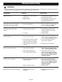
1
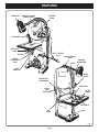
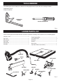
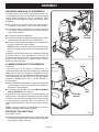
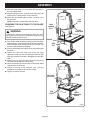
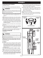
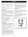
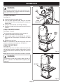
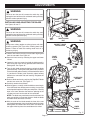
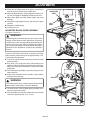
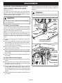
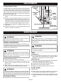
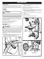
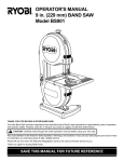
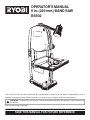
OPERATOR'S MANUAL
9 in. (229 mm) BAND SAW
BS902
Your new Band Saw has been engineered and manufactured to Ryobi's high standards for dependability, ease of
operation, and operator safety. Properly cared for, it will give you years of rugged, trouble-free performance.
WARNING: To reduce the risk of injury, the user must read and understand the operator's manual before using
this product.
Thank you for buying a Ryobi tool.
SAVE THIS MANUAL FOR FUTURE REFERENCE
TABLE OF CONTENTS
Introduction ...................................................................................................................................................................... 2
Rules for Safe Operation ............................................................................................................................................. 3-5
Electrical ........................................................................................................................................................................... 6
Glossary of Terms ............................................................................................................................................................ 7
Features ....................................................................................................................................................................... 7-9
Unpacking ........................................................................................................................................................................ 9
Tools Needed ................................................................................................................................................................. 10
Loose Parts List ............................................................................................................................................................. 10
Assembly ................................................................................................................................................................... 11-14
Operation ................................................................................................................................................................. 14-16
Adjustments ............................................................................................................................................................. 17-20
Maintenance ............................................................................................................................................................ 20-21
Troubleshooting ............................................................................................................................................................. 22
Parts Ordering / Service ................................................................................................................................................. 24
INTRODUCTION
IMPORTANT
Servicing requires extreme care and knowledge and should
be performed only by a qualified service technician. For
service we suggest you return the tool to your nearest RYOBI
AUTHORIZED SERVICE CENTER for repair. When servicing, use only identical Ryobi replacement parts.
WARNING:
Do not attempt to use the tool until you read thoroughly
and understand completely the operator’s manual. Pay
close attention to the safety rules, including Dangers,
Warnings, and Cautions. If you use this tool properly
and only for what it is intended, you will enjoy years of
safe, reliable service.
WARNING:
The operation of any power tool can result in foreign objects being thrown into your eyes, which can
result in severe eye damage. Before beginning tool operation, always wear safety goggles or safety
glasses with side shields and a full face shield when needed. We recommend Wide Vision Safety
Mask for use over eyeglasses or standard safety glasses with side shields. Always wear eye
protection which is marked to comply with ANSI Z87.1.
Look for this symbol to point out important safety precautions. It
means attention!!! Your safety is involved.
Page 2
RULES FOR SAFE OPERATION
The purpose of safety symbols is to attract your attention to possible dangers. The safety symbols, and the
explanations with them, deserve your careful attention and understanding. The safety warnings do not by themselves
eliminate any danger. The instructions or warnings they give are not substitutes for proper accident prevention
measures.
Symbol
Meaning
DANGER: Indicates an imminently hazardous situation which, if not avoided, will result in death or
serious injury.
WARNING: Indicates a potentially hazardous situation which, if not avoided, could result in death or
serious injury.
CAUTION: Indicates a potentially hazardous situation which, if not avoided, may result in minor or
moderate injury. It may also be used to alert against unsafe practices that may cause property damage.
NOTE:
Advises you of information or instructions vital to the operation or maintenance of the equipment.
SAFETY AND INTERNATIONAL SYMBOLS
This operator's manual describes safety and international symbols and pictographs that may appear on this product.
Read the operator's manual for complete safety, assembly, operating and maintenance, and repair information.
SYMBOL
MEANING
• Do not expose to rain or use in damp locations.
NO HANDS SYMBOL
• Failure to keep your hands away from the blade
will result in serious personal injury.
Page 3
RULES FOR SAFE OPERATION
Safe operation of this power tool requires that you read and
understand this operator's manual and all labels affixed to
the tool. Safety is a combination of common sense, staying
alert, and knowing how your band saw works.
READ ALL INSTRUCTIONS
KNOW YOUR POWER TOOL. Read the operator's
manual carefully. Learn the applications and limitations
as well as specific potential hazards related to this tool.
GUARD AGAINST ELECTRICAL SHOCK by preventing
body contact with grounded surfaces. For example: pipes,
radiators, ranges, refrigerator enclosures.
KEEP GUARDS IN PLACE and in working order. Never
operate the tool with any guard or cover removed. Make
sure all guards are operating properly before each use.
REMOVE ADJUSTING KEYS AND WRENCHES. Form
habit of checking to see keys and adjusting wrenches
are removed from tool before turning it on.
KEEP THE WORK AREA CLEAN. Cluttered work areas
and work benches invite accidents.
DON’T USE IN DANGEROUS ENVIRONMENTS. Do not
use power tools near gasoline or other flammable liquids,
in damp or wet locations or expose them to rain. Keep
work area well lighted.
KEEP CHILDREN AND VISITORS AWAY. All visitors
should wear safety glasses and be kept a safe distance
from work area.
MAKE WORKSHOP CHILDPROOF with padlocks,
master switches, or by removing starter keys.
DON’T FORCE THE TOOL. It will do the job better and
safer at the rate for which it was designed.
USE THE RIGHT TOOL. Do not force the tool or
attachment to do a job for which it was not designed.
USE THE PROPER EXTENSION CORD. Make sure your
extension cord is in good condition. When using an
extension cord, be sure to use one heavy enough to carry
the current your product will draw. An undersized cord
will cause a drop in line voltage resulting in loss of power
and overheating. A wire gage size (A.W.G.) of at least 16
is recommended for an extension cord 25 feet or less in
length. If in doubt, use the next heavier gage. The smaller
the gage number, the heavier the cord.
WEAR PROPER APPAREL. Do not wear loose clothing,
neckties, or jewelry that can get caught in the tool’s
moving parts and cause personal injury. Nonslip footwear
is recommended when working outdoors. Wear protective
hair covering to contain long hair.
ALWAYS WEAR SAFETY GLASSES WITH SIDE
SHIELDS. Everyday eyeglasses have only impactresistant lenses; they are NOT safety glasses.
SECURE WORK. Use clamps or a vise to hold work when
practical. It’s safer than using your hand and it frees both
hands to operate tool.
DO NOT OVERREACH. Keep proper footing and balance
at all times.
MAINTAIN TOOLS WITH CARE. Keep tools sharp and
clean for best and safest performance. Follow instructions
for lubricating and changing accessories.
DISCONNECT ALL TOOLS. When not in use, before
servicing, or when changing attachments, blades, bits,
cutters, etc., all tools should be disconnected from power
source.
REDUCE THE RISK OF UNINTENTIONAL STARTING.
Be sure switch is off when plugging in.
USE RECOMMENDED ACCESSORIES. Consult the
operator’s manual for recommended accessories. The use
of improper accessories may cause risk of injury.
NEVER STAND ON TOOL. Serious injury could occur if
the tool is tipped or if the blade is unintentionally contacted.
CHECK DAMAGED PARTS. Before further use of the
tool, a guard or other part that is damaged should be
carefully checked to determine that it will operate properly
and perform its intended function. Check for alignment of
moving parts, binding of moving parts, breakage of parts,
mounting and any other conditions that may affect its
operation. A guard or other part that is damaged must be
properly repaired or replaced by an authorized service
center to avoid risk of personal injury.
DIRECTION OF FEED. Feed work into a blade or cutter
against the direction or rotation of the blade or cutter only.
NEVER LEAVE TOOL RUNNING UNATTENDED.
TURN POWER OFF. Don’t leave tool until it comes to a
complete stop.
DON’T ABUSE CORD. Never carry tool by the cord or
yank it to disconnect from receptacle. Keep cord from
heat, oil, and sharp edges.
PROTECT YOUR LUNGS. Wear a face or dust mask if
the cutting operation is dusty.
PROTECT YOUR HEARING. Wear hearing protection
during extended periods of operation.
BLADE COASTS AFTER TURN OFF.
KEEP TOOL DRY, CLEAN, AND FREE FROM OIL AND
GREASE. Always use a clean cloth when cleaning. Never
use brake fluids, gasoline, petroleum-based products, or
any solvents to clean tool.
INSPECT TOOL CORDS AND EXTENSION CORDS
PERIODICALLY and, if damaged, have repaired by a
qualified service technician. Stay constantly aware of cord
location and keep it well away from the rotating wheel.
NEVER USE IN AN EXPLOSIVE ATMOSPHERE.
Normal sparking of the motor could ignite fumes.
USE ONLY OUTDOOR EXTENSION CORDS with
approved ground connection that are intended for use
outdoors and so marked.
BE SURE THE BLADE PATH IS FREE OF NAILS.
Inspect for and remove nails from lumber before cutting.
Page 4
RULES FOR SAFE OPERATION
AVOID AWKWARD OPERATIONS AND HAND POSITIONS where a sudden slip could cause your hand to
move into the blade. ALWAYS make sure you have good
balance.
ALLOW THE MOTOR TO COME UP TO FULL SPEED
before starting a cut to avoid binding or stalling.
DO NOT USE TOOL IF SWITCH DOES NOT TURN IT
ON AND OFF. Have defective switches replaced by an
authorized service center.
REPLACEMENT PARTS. All repairs, whether electrical
or mechanical, should be made by a qualified service
technician at an authorized service center.
WHEN SERVICING use only identical Ryobi replacement
parts. Use of any other parts may create a hazard or cause
product damage.
KEEP HANDS AWAY FROM CUTTING AREA. Do not
hand hold pieces so small that your fingers go under
the blade guard. Do not reach underneath work or in
blade cutting path with your hands and fingers for any
reason.
NEVER CUT MORE THAN ONE PIECE AT A TIME or
stack more than one workpiece on the saw table at a
time.
FIRMLY CLAMP OR BOLT your saw to a stable, level
workbench or table. The most comfortable table height
is approximately waist height.
DO NOT FEED THE MATERIAL TOO QUICKLY. Do not
force the workpiece against the blade.
USE ONLY CORRECT BLADES. Use the right blade
size, style and cutting speed for the material and the type
of cut. Blade teeth should point down toward the table.
BEFORE MAKING A CUT, BE SURE ALL ADJUSTMENTS ARE SECURE.
ALWAYS SUPPORT LARGE WORKPIECES while cutting to minimize risk of blade pinching and kickback. Saw
may slip, walk or slide while cutting large or heavy boards.
DO NOT REMOVE JAMMED CUTOFF PIECES until
blade has stopped.
NEVER START THE TOOL when the blade is in contact
with the workpiece.
NEVER TOUCH BLADE or other moving parts during
use.
BEFORE CHANGING THE SETUP, REMOVING
COVERS, GUARDS OR BLADES, unplug the saw
and remove the switch key.
HOLD THE WORKPIECE firmly against the saw table.
TO AVOID ACCIDENTAL BLADE CONTACT, minimize
blade breakage, and provide maximum blade support,
always adjust the blade guide assembly to just clear the
workpiece.
KEEP BLADES CLEAN, SHARP, AND WITH SUFFICIENT SET. Sharp blades minimize stalling and kickbacks.
ALWAYS TURN OFF SAW before disconnecting it to
avoid accidental starting when reconnecting to a power
source.
DO NOT OPERATE THIS TOOL WHILE UNDER THE
INFLUENCE OF DRUGS, ALCOHOL OR ANY
MEDICATION.
STAY ALERT AND EXERCISE CONTROL. Watch what
you are doing and use common sense. Do not operate
tool when you are tired. Do not rush.
MAKE SURE WORK AREA HAS AMPLE LIGHTING to
see the work and that no obstructions will interfere with
safe operation BEFORE performing any work using your
saw.
The blade guides have been preset at the factory. These
settings are functional for some applications. We recommend that you check and adjust blade guide settings before first use of your saw. Refer to “Adjusting thrust bearings, blade guide support, and blade guides” procedures explained in the adjustments section of this
operator’s manual.
SAVE THESE INSTRUCTIONS. Refer to them frequently
and use them to instruct other users. If you loan someone
this tool, loan them these instructions also.
WARNING:
Some dust created by power sanding, sawing, grinding,
drilling, and other construction activities contains
chemicals known to cause cancer, birth defects or
other reproductive harm. Some examples of these
chemicals are:
• lead from lead-based paints,
• crystalline silica from bricks and cement and other
masonry products, and
• arsenic and chromium from chemically-treated
lumber.
Your risk from these exposures varies, depending on
how often you do this type of work. To reduce your
exposure to these chemicals, work in a well ventilated
area, and work with approved safety equipment, such
as those dust masks that are specially designed to filter
out microscopic particles.
SAVE THESE INSTRUCTIONS
Page 5
ELECTRICAL
EXTENSION CORDS
ELECTRICAL CONNECTION
Use only 3-wire extension cords that have 3-prong grounding plugs and 3-pole receptacles that accept the tool's plug.
When using a power tool at a considerable distance from the
power source, use an extension cord heavy enough to carry
the current that the tool will draw. An undersized extension
cord will cause a drop in line voltage resulting in a loss of
power and causing the motor to overheat. Use the chart
provided below to determine the minimum wire size required
in an extension cord. Only round jacketed cords listed by
Underwriter's Laboratories (UL) should be used.
Length of Extension Cord
Wire Size (A.W.G.)
Up to 25 feet
16
26-50 feet
16
51-100 feet
16
When working with the tool outdoors, use an extension cord
that is designed for outside use. This is indicated by the
letters WA on the cord's jacket.
Before using an extension cord, inspect it for loose or
exposed wires and cut or worn insulation.
Your band saw is powered by a precision built electric motor.
It should be connected to a power supply that is 120 volts,
60Hz, AC only (normal household current). Do not operate this tool on direct current (DC). A substantial voltage drop
will cause a loss of power and the motor will overheat. If the
machine does not operate when plugged into an outlet,
double check the power supply.
CAUTION:
Keep the cord away from the cutting area and position
the cord so that it will not be caught on materials, tools,
or other objects during cutting.
GROUNDING INSTRUCTIONS
In the event of a malfunction or breakdown, grounding
provides a path of least resistance for electric current to
reduce the risk of electric shock. This tool is equipped with an
electric cord having an equipment-grounding conductor and
a grounding plug. The plug must be plugged into a matching
outlet that is properly installed and grounded in accordance
with all local codes and ordinances.
Do not modify the plug provided. If it will not fit the outlet, have
the proper outlet installed by a qualified electrician. Improper
connection of the equipment-grounding conductor can result
in a risk of electric shock. The conductor, with insulation
having an outer surface that is green with or without yellow
stripes, is the equipment-grounding conductor. If repair or
replacement of the electric cord or plug is necessary, do not
connect the equipment-grounding conductor to a live terminal.
Check with a qualified electrician or service personnel if the
grounding instructions are not completely understood, or if in
doubt as to whether the tool is properly grounded.
GROUNDING
PIN
Repair or replace a damaged or worn cord immediately.
COVER OF GROUNDED
OUTLET BOX
Fig. 1
This tool is intended for use on a circuit that has an outlet like
the one shown in Figure 1. It also has a grounding pin like the
one shown.
Page 6
GLOSSARY OF TERMS FOR WOODWORKING
Bevel Cut
A cutting operation made with the saw table at any angle
other than 90° to the blade.
Compound Cut
A compound cut is a cut made using a miter angle and a
bevel angle at the same time.
Crosscut
A cutting or shaping operation made across the grain or the
width of the workpiece.
Freehand (for band saw)
Performing a cut without the workpiece properly supported
on the saw table.
Gum
A sticky, sap-based residue from wood products.
Kerf
The material removed by the blade in a through cut or the slot
produced by the blade in a non-through cut or partial cut.
Kickback
A hazard that can occur when the blade binds or stalls,
throwing the workpiece back toward operator.
Leading End
The end of the workpiece pushed into the cutting tool first.
Miter Cut
A cutting operation made with the workpiece at any angle to
the blade other than 90°.
Push Stick
A device used to feed the workpiece through the saw blade
during narrow cutting operations. It helps keep the operator's
hands well away from the blade.
Resin
A sticky, sap-based substance that has hardened.
Ripping
A cutting operation along the length of the workpiece.
Saw Blade Path
The area directly in line — over, under, behind or in front of
the blade. As it applies to the workpiece, that area which will
be or has been cut by the blade.
Set
The distance that the tip of the saw blade tooth is bent (or set)
outward from the face of the blade.
SFPM
3,000 surface feet per minute, used in reference to surface
speed of blade.
Throw-Back
Saw throwing back a workpiece in a manner similar to a
kickback. Usually associated with a cause other than the kerf
closing, such as a workpiece being dropped into the blade or
being placed inadvertently in contact with the blade.
Through Sawing
Any cutting operation where the blade extends completely
through the thickness of the workpiece.
Workpiece
The item on which the cutting operation is being done. The
surfaces of a workpiece are commonly referred to as faces,
ends, and edges.
Worktable
The surface on which the workpiece rests while performing
a cutting or sanding operation.
Resaw
A cutting operation to reduce the thickness of the workpiece
to make thinner pieces.
FEATURES
PRODUCT SPECIFICATIONS:
Blade Width
Blade Length
Frame to Blade Capacity
Cutting Thickness Capacity
Table Size
1/8 in. to 3/8 in.
(3 mm to 10 mm)
59-1/4 - 59-1/2 in.
(1505mm - 1511mm)
9 in.
(229 mm)
3-5/8 in.
(92.07 mm)
Input
Rating
No Load Speed
Net Weight
Dust Port
11-13/16 in. x 11-13/16 in.
(30 cm x 30 cm)
Page 7
2.5 Amperes
120 Volt, 60Hz
AC Only
3,000 SFPM
37 lbs.
(17.8 kg)
2-1/4 in.
(57.15 mm)
FEATURES
WORKLIGHT
RAPIDSET™ BLADE
TENSION LEVER
TRACKING
KNOB
LOCK KNOB
TABLE LOCK
KNOB
DUST EXHAUST
PORT
BLADE TENSION
SCALE
KNOB
ANGLE
ADJUSTMENT
KNOB
LATCH
TRACKING
VIEW WINDOW
SCALE
INDICATOR
BLADE
GUARD
TRACKLOCK®
BLADE GUIDE
SWITCH
AND
SWITCH KEY
SAW BLADE
MITER
GAUGE
SAW TABLE
RIP
FENCE
LATCH
Fig. 2
Page 8
FEATURES
KNOW YOUR BAND SAW
Saw Blade
Before attempting to use, familiarize yourself with all the
operating features and safety requirements of your saw.
Saw comes with a standard 1/4 in. (6 mm) blade.
Angle Adjustment Knob
Your band saw has a square 11-13/16 in. (30 cm) aluminum
saw table with tilt control for maximum accuracy. The throat
plate, installed in the saw table at the factory, allows for blade
clearance.
Tilts the saw table for bevel cutting.
Blade Guard
Protects the operator from coming in contact with the blade.
Blade Guide Knob with Lock Lever
Use the blade guide knob and lock lever to adjust the blade
guide assembly to keep the blade from twisting or breaking.
Always lock the blade guide assembly in place before
turning on the band saw.
Dust Exhaust Port
A 2-1/4 in. (57.15 mm) dust exhaust port makes dustless
cutting possible by blowing the dust away from the user.
Attach to the dust exhaust port when using a dust collection
system or shop vac.
Latch
Easy open latches allow front cover to be opened for making
adjustments.
Saw Table with Throat Plate
Scale and Scale Indicator
The scale and scale indicator show the angle or degree the
saw table is tilted for bevel cutting.
Switch and Switch Key
Your band saw has an easy access power switch. To lock in
the OFF position, remove the yellow switch key. Place the
key in a location inaccessible to children and others not
qualified to use the tool.
Table Lock Knob
Loosening the table lock knob allows the saw table to be
tilted at different angles. Tightening the table lock knob locks
the saw table in place.
Tracking Knob
Adjusts tracking to keep blade centered on the wheels.
Miter Gauge
This gauge aligns the wood for a crosscut. The easy-to-read
indicator shows the exact angle for a miter cut, with positive
stops at 90° and 45°.
Tracking View Window
RapidSet™ Blade Tension Lever
TrackLock® Blade Guides
Controls blade tension when changing blades and making
adjustments for various sawing applications.
Upper and lower TrackLock® blade guides helps keep the
blade from twisting during operation.
Rip Fence
Worklight
A sturdy metal fence guides the workpiece and is secured
with the rip fence handle.
Your band saw comes equipped with a worklight that lights
the work area for safer, more accurate cuts.
The tracking view window makes tracking adjustments
easier to see.
UNPACKING
WARNING:
WARNING:
To prevent accidental starting that could cause possible
serious personal injury, assemble all parts to your saw
before connecting it to power supply. Saw should never
be connected to power supply when you are assembling
parts, making adjustments, installing or removing blades,
or when not in use.
If any parts are missing, do not operate this tool until the
missing parts are replaced. Failure to do so could result
in possible serious personal injury.
Do not discard the packing materials until you have carefully inspected the saw, identified all parts, and satisfactorily operated your new saw.
Carefully remove all parts from the carton and place the
saw on a level work surface. Separate and check against
the list of loose parts.
NOTE: If any parts are damaged or missing, do not attempt
to plug in the power cord and turn the switch on until the
damaged or missing parts are obtained and are installed
correctly.
Page 9
TOOLS NEEDED
The following tools (not included) are needed for checking adjustments of your saw or for installing the blade:
Combination Square
Phillips Screwdriver
COMBINATION
SQUARE
PHILLIPS SCREWDRIVER
Fig. 3
LOOSE PARTS LIST
Check all loose parts from the box with the list below. Assemble according to the instructions on the following pages.
Hex Key, 4 mm ................................................................ 1
Rip Fence ......................................................................... 1
Miter Gauge ..................................................................... 1
Saw Table ........................................................................ 1
Wing Screw ...................................................................... 1
Wing Nut .......................................................................... 1
Table Aligning Bolt ...........................................................
Flat Head Screw ..............................................................
Worklight ..........................................................................
Washer .............................................................................
Switch Key .......................................................................
Operator’s Manual (not shown) .......................................
1
3
1
1
1
1
WORKLIGHT
SWITCH
KEY
MITER GAUGE
SAW TABLE
RIP FENCE
WING NUT
WING SCREW
4 mm HEX KEY
WASHER
FLAT HEAD SCREW
TABLE ALIGNING
BOLT
Fig. 4
Page 10
ASSEMBLY
MOUNTING BAND SAW TO WORKBENCH
If the band saw is to be used in a permanent location, we
recommend that you secure it to a workbench or other stable
surface. When mounting the saw to a workbench, holes
should be drilled through the supporting surface of the
workbench.
Each hole in the saw base should be bolted securely
using bolts, lock washers, and hex nuts (not included).
Place band saw on the workbench. Using the saw base
as a pattern, locate and mark the holes where the band
saw is to be mounted.
Drill holes through the workbench.
Place band saw on the workbench aligning holes in the
saw base with the holes drilled in the workbench.
Insert bolts (not included) and tighten securely with lock
washers and hex nuts (not included).
NOTE: All bolts should be inserted from the top. Install
the lock washers and hex nuts from the underside of the
bench.
Supporting surface where band saw is mounted should be
examined carefully after mounting to insure that no
movement during use can result. If any tipping or walking is
noted, secure workbench or support surface before
beginning cutting operation.
HOLES IN
SAW BASE
Fig. 5
CLAMPING BAND SAW TO WORKBENCH
See Figure 5.
SCREW
If the band saw is to be used as a portable tool, it is
recommended that you fasten it permanently to a mounting
board that can easily be clamped to a workbench or other
supporting surface. The mounting board should be of sufficient
size to avoid tipping of saw while in use. Any good grade
plywood or chipboard with a 3/4 in. (19 mm) thickness is
recommended.
Mount saw to board using holes in saw base as a template
for hole pattern. Locate and mark the holes where the
band saw is to be mounted.
Follow the last three steps in the section Mounting Band
Saw to Workbench, shown above.
If lag bolts are used, make sure they are long enough to go
through holes in the saw base and material the saw is being
mounted to. If machine bolts are being used, make sure bolts
are long enough to go through holes in the saw base, the
material being mounted to, and the lock washers and hex
nuts.
NOTE: It may be necessary to countersink hex nuts and
washers on bottom side of mounting board.
MOUNTING THE SAW TABLE
SAW
TABLE
SAW TABLE
BRACKET
Fig. 6
See Figures 6 and 7.
Standing at the front of the band saw, slide the saw table
pass the blade and through the slot moving from the right
side of the saw table to the left.
Page 11
ASSEMBLY
Align the screw holes in the saw table with the holes in
the saw table bracket.
Using the phillips screws, attach the saw table to the saw
table bracket. Tighten phillips screws securely.
Attach the table aligning bolt, washer, and wing nut to
the saw table.
NOTE: The wing nut goes below the saw table.
LOCK
KNOB
TABLE
ALIGNING
BOLT
SQUARING THE SAW TABLE TO THE BLADE
See Figure 8.
BLADE
GUIDE KNOB
WARNING:
Failure to turn the saw off, remove the switch key, and
unplug the saw could result in accidental starting causing
possible serious personal injury.
Turn the lock knob counterclockwise to unlock the blade
guide assembly. Turning the blade guide knob clockwise,
raise the blade guide assembly as far as it will go. Turn
the lock knob clockwise to retighten.
Place a small combination square on the saw table beside
the blade.
Loosen the table lock knob and rotate the angle
adjustment knob to tilt the saw table up or down to align
table 90° to blade (0° position). Retighten the table lock
knob.
Using a hex key, adjust the zero stop set screw until the
set screw just touches the saw housing.
Check squareness of the saw table to the blade. Make
readjustments if necessary.
Loosen screw on scale indicator with a phillips
screwdriver and align scale indicator to zero.
Tighten all screws securely.
WASHER
WING
NUT
Fig. 7
ZERO STOP
SET SCREW
SAW
BLADE
BLADE
GUARD
SMALL
COMBINATION
SQUARE
Fig. 8
Page 12
ASSEMBLY
ADJUSTING BLADE TENSION
See Figures 9 and 10.
Turn off and unplug the saw. Remove the switch key.
WARNING:
Failure to turn the saw off, remove the switch key, and
unplug the saw could result in accidental starting causing
possible serious personal injury.
Before using the band saw, turn the blade tension knob
on the top of the saw clockwise to engage tension. See
Figure 9.
NOTE: Adjustments of blade tension can be made at anytime.
Another method of checking blade tension has to do with the
sound the blade makes when plucked like a guitar string.
Pluck the back straight edge on the coasting side opposite
the blade guides while turning the tension knob. Sound
should be a musical note. Sound becomes higher pitched
as tension increases.
Check the position of the blade on the lower tire. The
blade should be completely on the tire. If not, adjust the
tracking until the blade is on both tires.
Rotate the upper wheel by hand in a clockwise direction
for a few more turns. Make sure the blade stays in the
same location on the tires. Readjust, if necessary, until
blade is tracking properly.
Close front cover and relatch.
NOTE: The 1/8 in. (3 mm) blade may not track properly in
the center of the wheel. It may be better to track this blade
on the back half of the upper wheel.
TO DECREASE
TENSION
Using either method to check blade tension can be developed
with practice.
Never increase blade tension so tight as to completely
compress the spring. When completely compressed, the
spring can no longer act as a shock absorber.
TO INCREASE
TENSION
BLADE TENSION KNOB
Fig. 9
NOTE: Too much tension may cause the blade to break. Too
little tension may cause the blade to slip on the wheels.
BLADE
TENSION
KNOB
TRACKING THE BLADE
See Figure 10.
WARNING:
Failure to turn the saw off, remove the switch key, and
unplug the saw could result in accidental starting causing
possible serious personal injury.
BLADE ON
WHEEL
NOTE: Adjust blade tension properly before making tracking adjustments. Check that the blade guides are not interfering with the blade.
To Adjust:
Open the front cover by releasing the upper and lower
latches. Watch the blade’s position on the upper tire
through the tracking view window as, by hand, you slowly
turn the upper wheel clockwise. If the blade moves away
from the center of the tire, the tracking must be adjusted.
Retighten hex nut.
TRACKING
VIEW
WINDOW
BLADE
TRACKING
KNOB
If the blade has moved left or right of center:
NOTE: It may be necessary to loosen the hex nut for a larger
range of adjustments. Be sure to retighten after adjusting.
Turn the blade tracking knob (clockwise if blade has
moved left and counterclockwise if blade has moved right)
while turning the wheel by hand until the blade moves
back and rides in the center of the tire.
Page 13
Fig. 10
ASSEMBLY
ATTACHING THE WORKLIGHT
WORKLIGHT
BRACKET
See Figure 11.
WARNING:
Failure to turn the saw off, remove the switch key, and
unplug the saw could result in accidental starting causing
possible serious personal injury.
Open the cover of the saw housing.
Slide the worklight bracket into the slot at the back of the
band saw housing and into the slots on the inside of the
band saw.
Securely tighten the wing screw clockwise to hold the
worklight firmly in place.
Close the saw housing cover.
IMPORTANT SAFETY INSTRUCTIONS
This worklight has a polarized plug (one blade wider than the
other) as a feature to reduce the risk of electric shock. This
plug will fit in a polarized outlet onlly one way. If the plug does
not fit fully in the outlet, reverse the plug. If it still does not fit,
contact a qualified electrician. Never use with an extension
cord unless the plug can be fully inserted. Do not alter the
plug.
Fig. 11
OPERATION
CUTTING PROCEDURES
WARNING:
Read and understand all instructions. Failure to follow
all instructions may result in electric shock, fire, and/or
serious personal injury.
WARNING:
To avoid blade contact, adjust the blade guide assembly
to just clear the workpiece. Failure to do so could result
in serious personal injury.
BASIC OPERATION OF THE BAND SAW
A band saw is basically a “curve cutting” machine that
can also be used for straight-line cutting operations like
cross cutting, ripping, mitering, beveling, compound
cutting, and resawing. It is not capable of making inside
or non-through cuts.
This band saw is designed to cut wood and wood
composition products only.
Before starting a cut, watch the saw run. If you experience
excessive vibration or unusual noise, stop immediately.
Turn the saw off, remove the switch key, and unplug the
saw. Do not restart until locating and correcting the
problem.
Hold the workpiece firmly against the saw table.
Use gentle pressure and both hands when feeding the
work into the blade. Do not force the work; allow the
blade to cut.
The smallest diameter circle that can be cut is determined
by blade width. A 1/4 in. (6 mm) wide blade will cut a
minimum diameter of 1-1/2 in. (38 mm); a 1/8 in. (3 mm)
wide blade will cut a minimum diameter of 1/2 in. (13
mm).
Keep your hands away from the blade. Do not hand hold
pieces so small your fingers will go under the blade guard.
Avoid awkward operations and hand positions where a
sudden slip could cause serious injury from contact with
the blade. Never place hands in blade path.
Use extra supports (tables, saw horses, blocks, etc.)
when cutting large, small or awkward workpieces.
Never use a person as a substitute for a table extension
or as additional support for a workpiece that is longer or
wider than the basic saw table.
When cutting irregularly shaped workpieces, plan your
work so it will not pinch the blade. For example, a piece
of molding must lay flat on the saw table. Workpieces
must not twist, rock or slip while being cut.
When backing up the workpiece, the blade may bind in the
kerf (cut). This is usually caused by sawdust clogging the
Page 14
OPERATION
kerf or when the blade comes out of the guides. If this
happens:
Wait until the saw has come to a full and complete stop.
Place the switch in the OFF position then remove the
switch key from the switch assembly. Store key in a safe
place.
Unplug the saw from the power source.
Wedge the kerf open with a flat screwdriver or wooden
wedge.
Open front cover and turn the upper wheel by hand while
backing up the workpiece.
RELIEF CUTS
Relief cuts are made when an intricate curve (too small a
radius for the blade) is to be cut. Cut through a scrap
section of the workpiece to curve in pattern line then
carefully back the blade out. Several relief cuts should be
made for intricate curves before following the pattern line
as sections are cutoff of curve “relieving” blade pressure.
SCROLL CUTTING
For general type scroll cutting, follow the pattern lines by
pushing and turning the workpiece at the same time. Do
not try to turn the workpiece while engaged in the blade
without pushing it – the workpiece could bind or twist the
blade.
With the exception of the workpiece and related support
devises, clear everything off the saw table before turning
the saw on.
Properly support round materials such as dowel rods or
tubing because they have a tendency to roll during a cut
causing the blade to “bite”. To avoid this, always use a
“V” block or clamp workpiece to a miter gauge
Before removing loose pieces from the saw table, turn
saw off and wait for all moving parts to stop.
LOCKING THE SWITCH
See Figure 12.
Wait until the saw has come to a full and complete stop.
Place the switch in the OFF position, remove the switch
key from the switch assembly. Store key in a safe place.
BEFORE LEAVING THE SAW
See Figure 12.
Wait until the saw has come to a full and complete stop.
Place the switch in the OFF position, remove the switch
key from the switch assembly. Store key in a safe place.
Unplug the saw from the power source.
Make workshop childproof.
Lock the shop.
REMOVING JAMMED MATERIAL
ON
Never remove jammed cutoff pieces until the blade has
come to a full and complete stop.
Place the switch in the OFF position, remove the switch
key from the switch assembly.
Unplug the saw from the power source before removing
jammed material.
OFF
AVOIDING INJURY
Make sure saw is level and does not rock. Saw should
always be on a firm, level surface with plenty of room for
handling and properly supporting the workpiece.
Bolt saw to the support surface to prevent slipping,
walking or sliding during operations like cutting long,
heavy boards.
Turn saw off, remove switch key, and unplug cord from
the power source before moving the saw.
Do not remove jammed cutoff pieces until blade has come
to a full and complete stop.
Choose the right size and style blade for the material
and type of cut you plan to do.
Make sure that the blade teeth point down toward the
saw table, that the blade guides, thrust bearings, and
blade tension are properly adjusted, that the blade guide
knob is tight, and that no parts have excessive play.
To avoid accidental blade contact, minimize blade
breakage, and provide maximum blade support, always
adjust the blade guide assembly to just clear the
workpiece.
Use only recommended accessories.
Page 15
SWITCH
KEY
Fig. 12
OPERATION
WARNING:
Do not allow familiarity with your saw make you careless. Remember that a careless fraction of a second is
sufficient to inflict severe injury.
SAW
TABLE
TILTING THE TABLE
See Figure 13.
TABLE LOCK
KNOB
Loosen the table lock handle slightly.
Turn the angle adjustment knob, tilting the saw table
toward the front of the saw housing until it reaches the
desired angle.
SCALE
INDICATOR
Fig. 13
Using the scale indicator, check angle markings.
Retighten the table lock handle to hold saw table securely
in place.
USING THE MITER GAUGE
See Figures 13 and 14.
The miter gauge can be turned 60° to the right or left.
Loose the lock knob on the miter gauge.
With the miter gauge in the miter gauge slot, rotate the
gauge until the desired angle is reached on the index
scale.
LOCK
KNOB
MITER
GAUGE
SLOT
Retighten the lock knob.
NOTE: For convenience, store the miter gauge in the slot
provide on the back of the band saw. See figure 13.
USING THE RIP FENCE
See Figure 15.
MITER
GAUGE
From either side of the saw table, slide the rip fence onto
the saw table. Check for a smooth, gliding action. Push the
locking handle down to automatically align and secure the
fence.
Note: Rip fence may be used on either side of the saw table.
Fig. 14
WARNING:
To reduce the risk of injury, always make sure the rip
fence is parallel to the blade before beginning any
operation.
RIP FENCE
Fig. 15
Page 16
ADJUSTMENTS
WARNING:
Failure to turn the saw off, remove the switch key, and
unplug the saw could result in accidental starting causing
possible serious personal injury.
BLADE
GUARD
INSTALLING AND ADJUSTING THE BLADE
SET SCREWS
See Figures 16 and 17.
WARNING:
Failure to turn the saw off, remove the switch key, and
unplug the saw could result in accidental starting causing
possible serious personal injury.
SAW
TABLE
WING
NUT
TABLE ALIGNING
BOLT
Fig. 16
WARNING:
Always wear safety goggles or safety glasses with side
shields to protect your eyes while uncoiling band saw
blades. Failure to heed this warning could result in a
serious eye injury.
Loosen and remove the wing nut and table aligning bolt
from the saw table. See Figure 16.
Open the front cover by releasing the upper and lower
latches.
Loosen the two set screws that hold the blade guard in
place using the 4 mm hex key provided then remove the
blade guard. See Figure 16.
Turn the lock knob counterclockwise to unlock the blade
guide assembly. Turning the blade guide knob (clockwise
raises the blade guide assembly; counterclockwise lowers
it), position the blade guide assembly about halfway
between the saw table and saw housing. Retighten the
lock knob.
Release blade tension by pushing the RapidSet™blade
tension lever to the left. See Figure 17.
Carefully remove the old blade.
Wearing gloves, carefully uncoil the blade at arms length.
If the new blade was oiled to prevent rusting, it may need
to be wiped to keep the oil from your workpiece. Carefully
wipe in the same direction the teeth are pointing so the
rag does not catch on the teeth of the saw blade.
NOTE: The blade may need to be turned inside out if the
teeth are pointing in the wrong direction. Hold the blade
with both hands and rotate it inward.
With the teeth of the blade toward the front of the saw
and facing downward, place the blade through the lower
blade guides and around the lower wheel. Pull down on
the upper wheel to place the saw blade on the wheel.
RAPIDSET™ BLADE
TENSION LEVER
BLADE
TENSION
KNOB
UPPER
WHEEL
BLADE GUIDE
ASSEMBLY
SAW BLADE
LOWER
BLADE
GUIDES
LOWER
WHEELS
Fig. 17
Page 17
ADJUSTMENTS
Slowly turn the upper wheel to the right or clockwise by
hand to center the blade on the rubber tires.
Adjust the blade tension; check or adjust the blade tracking and re-engage the RapidSet™blade tension lever.
Adjust both upper and lower blade guides and thrust
bearings.
Reattach the aligning bolt, washer, and wing nut. Tighten
securely.
Reattach the blade guard.
Close front cover.
BLADE GUIDE
KNOB
BLADE GUIDE
ASSEMBLY
LOCK
KNOB
ADJUSTING BLADE GUIDE ASSEMBLY
See Figures 18 and 19.
WARNING:
The blade guides have been preset at the factory. These
settings are functional for some applications. We recommend that you check and adjust blade guide settings before first use of your saw. Refer to “Adjusting thrust bearings, blade guide support, and blade guides” procedures
explained in the adjustments section of this operator’s
manual.
To prevent the blade from twisting or breaking, the blade
guide assembly should always be set approximately 1/8 in.
(3 mm) above the workpiece.
Turn the lock knob counterclockwise to unlock the blade
guide assembly.
As a guide, use a scrap piece of the same wood you are
about to cut to set the height of the blade guide assembly.
Adjust the blade guide assembly by turning the blade
guide knob.
Lock blade guide assembly in place by turning the lock
knob clockwise.
Always lock the blade guide assembly in place before
turning on the band saw.
Fig. 18
UNLOCK
LOCK
WARNING:
To avoid personal injury, maintain proper adjustment of
blade tension, blade guides, and thrust bearings.
To check tension, raise the blade guide assembly all the
way up to expose the blade.
Push the blade to the side with moderate force; the blade
should flex approximately 1/8 in. (3 mm).
Fig. 19
Page 18
ADJUSTMENTS
ADJUSTING THRUST BEARINGS, BLADE
GUIDE SUPPORT, AND BLADE GUIDES
See Figures 20 - 22.
The upper and lower blade guides and thrust bearings
support the band saw blade during cutting operations. The
adjustment of the guides and bearings should be checked
whenever a different blade is installed.
NOTE: The lower blade guide support screw is the top screw
located on the right of the saw housing under the table. See
Figure 21.
WARNING:
Never operate saw without blade guard secured in place.
To do so could result in possible serious personal injury.
WARNING:
BLADE
GUIDE
ASSEMBLY
Failure to turn the saw off, remove the switch key, and unplug
the saw could result in accidental starting causing possible
serious personal injury.
THRUST
BEARING
UPPER BLADE
GUIDE SUPPORT
To Adjust Thrust Bearings:
The thrust bearings support the back edge of the blade during
cutting. The blade should not contact the thrust bearings
when you stop cutting. It is important that both upper and
lower thrust bearings be adjusted equally.
NOTE: The thrust bearing screw is the upper cap screw
located on the right side of the blade guide assembly. It is
the lower cap screw on the right side of the saw housing
below the saw table for the lower bearing. See Figures 20
and 21.
Remove the blade guard by loosening the two phillips
screws.
Turn the lock knob counterclockwise to unlock the blade
guide assembly. Turning the blade guide knob clockwise,
raise the blade guide assembly as far as it will go. Turn
the lock knob clockwise to retighten.
Adjust the thrust bearings first. Using the 4 mm hex key,
loosen the thrust bearing screw.
Move the thrust bearing to within 1/64 in. (0.4 mm) of the
blade. Tighten the thrust bearing screw securely. Repeat
this procedure on the lower thrust bearing located below
the saw table.
Replace the blade guard if no additional adjustments are
to be made.
To Adjust Blade Guide Support:
Remove the blade guard by loosening the two phillips
screws.
Adjust the position of the blade guide assembly. Loosen
the bottom screw on the right side of the blade guide
assembly using the 4 mm hex key.
Slide the upper blade guide support on the shaft until
the front edge of the blade guides are about 1/64 in. (0.4
mm) behind the gullet of the blade. Tighten the screw
securely. Repeat this procedure for the lower blade guide
support.
Replace the blade guard if no additional adjustments are
to be made.
Page 19
THRUST
BEARING
SCREW
BLADE GUIDE
SUPPORT SCREW
BLADE GUIDE
SCREWS
BLADE GUARD REMOVED
FOR CLARIFICATION ONLY
Fig. 20
BLADE GUIDE
SUPPORT SCREW
BLADE GUIDE
SCREWS
THRUST
BEARING
SCREW
LOWER BLADE
GUIDE SUPPORT
THRUST BEARING
Fig. 21
ADJUSTMENTS
To Adjust Blade Guides:
BLADE GUIDE
ASSEMBLY
The blade guides help keep the blade from twisting and binding.
The blade will be ruined if the blade teeth hit the blade guides
while using the band saw. The set of teeth and the sharpened
edge of teeth will be damaged by hitting the blade guides.
Proper adjustment of the upper and lower blade guides will
prevent this from happening.
Remove the blade guard by loosening the two phillips
screws.
Loosen the two blade guide support screws that lock the
upper blade guides. Slide the two guides to within 1/32 in.
(0.8 mm) of the blade. Do not pinch the blade. Make sure
one guide is not further away from the blade than the other.
Retighten the two blade guide support screws securely.
Replace the blade guard if no additional adjustments are
to be made.
Repeat this procedure on the lower blade guides located
under the saw table. See Figure 21.
UPPER BLADE
GUIDE
SUPPORT
THRUST
BEARING
THRUST
BEARING
SCREW
BLADE GUIDES
BLADE GUIDE
SUPPORT SCREW
BLADE GUARD REMOVED
Fig. 22
FOR CLARIFICATION ONLY
MAINTENANCE
WARNING:
WARNING:
To ensure safety and reliability, all repairs should be
performed by an authorized service center.
GENERAL MAINTENANCE
Avoid using solvents when cleaning parts. Most plastics are
susceptible to damage from various types of commercial
solvents and may be damaged by their use. Use clean cloths
to remove dirt, carbon dust, etc.
WARNING:
Do not, at any time, let brake fluids, gasoline, petroleumbased products, penetrating oils, etc., come in contact
with plastic parts. They contain chemicals that can
damage, weaken or destroy plastic.
Keep your band saw clean.
Remove sawdust from the inside frequently.
Do not allow pitch to accumulate on the saw table, blade
guides, or thrust bearings. Clean them with gum and
pitch remover.
Apply a thin coat of automobile type wax to the saw
table’s top so the wood slides easily while cutting.
If the power cord is worn, cut or damaged in any way,
have it replaced immediately by a qualified service
technician. Failure to do so could result in serious
personal injury.
WARNING:
To avoid fire or electrocution, reassemble electric parts
with only identical replacement parts. Reassemble exactly
as originally assembled.
TIRES
Cleaning tires:
Pitch and sawdust accumulates on tires and needs to
be removed with a fine wire brush or a piece of wood.
Do not use a sharp knife or any kind of solvent.
Replacing tires:
Open front cover and remove saw blade. See section on
Installing and Adjusting the Blade, page 17.
Pry the worn tire away from the wheel carefully.
Stretch the new tire around the wheel.
Replace the saw blade and close the front cover.
BLADE GUIDES
WARNING:
See Figure 22.
To prevent accidental starting that could cause possible
serious personal injury, turn off the saw, remove the switch
key, and unplug the saw before working on the band saw.
MOTOR/ELECTRICAL
Blade guides may become rounded and worn during
use. Remove the blade guides and file or grind flat.
Replace blade guides when filing or grinding has worn
them down and they can no longer be properly secured
in place.
Frequently vacuum or blow out sawdust from the motor.
Page 20
MAINTENANCE
LUBRICATION
All the bearings in this tool are lubricated with a sufficient
amount of high grade lubricant for the life of the unit under
normal operating conditions. Therefore no further lubrication
is required.
Remove the nut and washer from the middle of the saw
housing. See Figure 24.
Pull the lower wheel away from the saw housing.
Remove the worn drive belt.
Place new drive belt on the pulley. As you slide the
pulley shaft back into the hole in the saw housing, place
the drive belt over the motor pulley.
BRUSHES
See Figure 23.
WARNING:
To prevent accidental starting that could cause possible
serious personal injury, turn off the saw, remove the switch
key, and unplug the saw before working on the band saw.
Replace the nut and washer on the pulley shaft and
retighten.
Replace saw blade.
Check thrust bearings and blade guides.
There is a brush located inside the saw housing, next to the
lower wheel. It helps protect the tire and wheel by brushing
off saw dust. As the brush becomes worn, it will need to be
adjusted or replaced.
Remove the screw then pull the brush off.
Place the new brush in the groove.
Retighten using the screw.
DRIVE BELT
See Figures 24 and 25.
WARNING:
To prevent accidental starting that could cause possible
serious personal injury, turn off the saw, remove the switch
key, and unplug the saw before working on the band saw.
Due to wear or breakage, the drive belt may need to be
replaced. The drive belt is located behind the lower wheel of
the band saw.
NUT
AND
WASHER
Remove the saw blade and set it aside. See section on
Installing and Adjusting the Blade, page 17.
TIRE
BRUSH
SCREW
LOWER
WHEEL
Fig. 24
PULLEY
SHAFT
DRIVE BELT
LOWER
WHEEL
MOTOR PULLEY
Fig. 23
Fig. 25
Page 21
TROUBLESHOOTING
WARNING:
To prevent accidental starting that could cause possible serious personal injury, turn off the saw, remove the switch key,
and unplug the saw from the power source before working on the band saw.
PROBLEM
CAUSE
SOLUTION
Motor will not run.
1. Problem with On-Off switch or
power cord.
2. Motor defective.
1. Have worn parts replaced before
using band saw again.
2. Do not attempt any repair. Have
tool repaired by a qualified
service technician.
Blade does not run in the approximate center of the upper wheel.
1. Not tracking properly.
1. Adjust tracking, See Adjustments
section, Tracking the Blade.
Band Saw slows down when
cutting.
1. Cutting too small a radius.
1. Stop feeding and back up the
material slightly until the band
saw speeds up.
2. Replace blade.
2. Dull blade.
Blade breaking.
1. Too much blade tension.
2. Kink in blade caused by cutting
too small radius or turning the
material too fast when cutting.
3. Thrust bearings scarred or not
rotating.
Saw is noisy when running.
1. Too much blade tension.
2. Blade guides and bearings
are in contact with the blade.
Blade will not cut straight.
Blade guides will not stay in position.
1. Blade guides and bearings not
properly adjusted.
1. Adjust tension. See Adjustments
section, Adjusting Blade Tension.
2. Use correct cutting technique.
See section, Operation.
3. Replace the thrust bearings.
1. Adjust tension. See Adjustments
section, Adjusting Blade Tension.
2. Adjust upper and lower blade
guides and bearings. See Adjustments sections, Adjusting Thrust
Bearings, Blade Guide Support,
and Blade Guides.
2. Worn or defective blade.
1. Adjust upper and lower blade
guides and bearings. See Adjustments sections, Adjusting Thrust
Bearings, Blade Guide Support,
and Blade Guides.
2. Replace blade.
1. Blade guide screws have
loosened.
1. Tighten blade guide screws
securely.
Page 22
NOTES
NOTES
Page 23
OPERATOR'S MANUAL
9 in. (229 mm) Band Saw
BS902
EXTENSION CORD CAUTION
**Ampere rating
When using a power tool at a considerable distance from a power
source, be sure to use an extension cord that has the capacity
to handle the current the tool will draw. An undersized cord will
cause a drop in line voltage, resulting in overheating and loss of
power. Use the chart to determine the minimum wire size required in an extension cord. Only round jacketed cords should
be used.
When working with a tool outdoors, use an extension cord that
is designed for outside use. This is indicated by the letters "WA"
on the cord's jacket.
Before using any extension cord, inspect it for loose or exposed
wires and cut or worn insulation.
(on tool data plate)
0-2.0
2.1-3.4
Cord Length
3.5-5.0
5.1-7.0
7.1-12.0 12.1-16.0
Wire Size (A.W.G.)
25'
16
16
16
16
14
14
50'
16
16
16
14
14
12
100'
16
16
14
12
10
—
CAUTION: Keep the extension cord clear of the working
area. Position the cord so that it will not get caught on workpiece, tools, or other obstructions while you are working with a
power tool.
**Used on 12 gauge - 20 amp circuit.
• SERVICE
Now that you have purchased your tool, should a need ever exist for repair parts or
service, simply contact your nearest Ryobi Authorized Service Center. Be sure to
provide all pertinent facts when you call or visit. Please call 1-800-525-2579 for your
nearest Ryobi Authorized Service Center. You can also check our web site at
www.ryobitools.com for a complete list of Authorized Service Centers.
• MODEL NO.
The model and serial numbers of your tool will be found on a plate attached to the motor
housing. Please record the serial number in the space provided below.
•
MODEL NUMBER
•
SERIAL NUMBER
BS902
RYOBI TECHNOLOGIES, INC.
1428 Pearman Dairy Road Anderson SC 29625
Post Office Box 1207
Anderson SC 29622-1207
Phone 1-800-525-2579
www.ryobitools.com
983000-267
07-04
Page 24