1
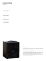
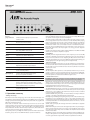
BThe Acoustic People Manual amp two English bottom line amp two Operating Manual Contents: 1. Introduction 2. Safety precautions 3. Concept 4. Controls 5. Operation summary 6. Technical specifications 7. Disposal regulations 1. Introduction Welcome to AER. It took us quite some time – so we are all the more happy that you have opted for the amp two. You have chosen a professional, compact and powerful amplifier which was designed especially for handling electric basses. When talking about authentic tone, not just the instrument but the entire signal chain is our reference. Instrument, pickup, cable, preamplifier, power amplifier and loudspeakers will create what you understand as ‘your tone’. We would appreciate if the amp two should become a vital element for you and wish you lots of enjoyment with it. 2. Safety precautions Please read and check if you have understood all instructions in this manual. down on dynamics, since the power amplifer, power supply or components hit their performance limit too early. Always take some basic safety precautions when using your amp two in order to minimize the risk of injury through fire or electric shock. By now it should be clear how complex the problem is and why we have taken quite a different approach to realise our tonal ideas, letting the ‘bass’ sound the way it wants to sound. Pay attention to all warnings, instructions and additional texts on the amp two. • An analogue 200 watts power amplifier with high dynamic reserves and a massive power supply provides the required output power. Always use an earthed power supply with the correct mains voltage. If you are in doubt about the power outlet’s ground, have it checked by a qualified technician. • The analogue signal processor monitors the signal so that the full output power can be called on without an ample ‘headroom’ which would be required otherwise. This will spare you space and weight, save the loudspeaker and provide constant, defined power amp conditions. Since this is a ‘closed system’ (power amp, processor and loudspeaker), all components can be perfectly matched while ensuring maximum efficiency without overstraining the system. We go to the limits, but not beyond. Use only fuses with the same current rating and trigger characteristic as replacements. Never mend fuses! Should a fuse blow again after a short while, the device needs to be checked. Pay attention to an unhindered air circulation in the amplifier’s surroundings. Never obstruct the air vents or grilles. Do not install or use your amp two in close proximity to water or if you are soaking wet yourself. Use your amp two in a safe place where nobody can step on cables or trip over and damage them. Do not install your amp two close to devices with strong electromagnetic fields such as large mains transformers, revolving machines, neon illumination etc. Do not lay signal cables parallel to power current cables. Cable up your amp two only if it is powered off. Always pull out the mains plug before you clean your amp two. Use a damp cloth for cleaning. Avoid the use of detergents and do not let any liquids enter into the unit. There are no user-servicable components inside your amp two. All maintenance, adjustment and repair works should be carried out by qualified staff only. Any unauthorized tampering will void our 2-year warranty. Keep this manual in a safe place! • We have chosen a 10” Sica instrument speaker chassis. This loudspeaker is highly suitable for a good bass response, especially in small ported cabinets. However, response characteristic, power handling and efficiency are interdependent factors so that dedicated bass chassis are always a bit lower in volume (approx. -3dB) than all-purpose speakers. The chassis has been tested for electrical and mechanical dependability according to AES standard. • The cabinet must withstand an enormous strain. It is made from 18 mm slotted, waterproof laminated birch plywood. The speaker chassis sits in a separate ported chamber to provide optimum uncoupling from the electronics. • Additional features: - Compressor - Adjustable XLR DI out - Line out, tuner out, headphones out - Footswitchable >Mute< and >Effect on/off< functions - Pre and post EQ inserts - Effects loop - Ground lift 3. Concept It was our ambition to put a professional unit with tremendous power, great features and outstanding tonal qualities into a small portable cabinet to make the ‘whole bass’ really happy. It’s been known for a long time how innovative today’s bass players are and how they love trying out new things. No doubt has the electric bass evolved into a ‘solo instrument’; for this reason the acoustic and technical requirements have gone up steeply and consequently the demands on the engineers as well. Straight talk A distortion-free, rock-solid and deep bass reproduction finds itself in constant opposition with physics, human perception and what product costing still accepts as in line with market conformity. A lot more energy is needed to give the fundamental bass notes the same volume as midrange or treble frequencies. The aim is a harmonic reproduction of the instrument’s pure tone, irrespective of resonance and formant ranges. In theory several problematic issues can add here in a negative way: • The human ear is far more sensitive at middle frequencies than at any other tonal ranges. • The instrument shows a very uneven reproduction of its individual spectrum. There are big differences in level, dispersion characteristic and sustain which produce frequency cancellations and peaks. • The reproduction of low bass frequencies requires more ‘energy’ and puts a lot more stress on the material as well as the components – the more so if extra amplification is made using equalization (e.g.: +15dB at 80 Hz equals the 5.6-fold voltage at this point or 31.6 times more power). Tonally speaking, the ‘bass’ is a very demanding instrument. Its reproductive capabilitiy extends over the entire audio spectrum. The level-relevant distribution, however, is very disproportionate. In general the lows and particularly the highs are greatly boosted to achieve a well-balanced signal which can then be further processed by sophisticated tone controls. The random interaction of pickups, pre and power amplifiers, each with numerous controls and varying quality degrees, will soon reveal limitations that will entail a mediocre signal-to-noise ratio of the whole audio chain and cut - Adjustable AUX input 4. Controls Left to right: input Instrument input (mono jack) middle Midrange control high / low Sensitivity selector switch high: high sensitivity low: low sensitivity freq. Center frequency of midrange control (200 … 2000 Hz) wide / narrow Bandwidth of midrange control (wide / narrow) gain input level control treble Treble control clip Overload indicator mute Amp mute (also controllable via footswitch) tone balance EQ balance shift (allows bass or treble accentuation or a combination of both.) compressor Dynamic compressor (for narrowing dynamic range) threshold Sets the level above which the compressor becomes active (clockwise lower level, i.e. higher compression). ratio Sets the compression ratio (clockwise higher compression). active Control indicator. Lights up when the compressor becomes active (depending on input signal) off / on Turns the compressor on/off. equalizer 3-band equalization (see also technical specifications) colour Midrange contour filter. Boosts presence range and slightly cuts low mids. bass Bass control bass boost Additional lower bass boost balance Alters the type of equalization as follows: Left stop: bass boost Center setting: bass and treble boost Right stop: treble boost and bass cut intensity Controls the intensity of the balance EQ Left stop: no effect Right stop: full effect as described under ’balance‘ master Overall volume control power Operation indicator Rear panel Left to right line out pre/post masterSwitches the line output pre or post master volume control headphones Caution! Use only stereo headphones. Please insert no mono cables! line out Preamp output sub out Unfiltered output for an active subwoofer footswitch Stereo footswitch socket, TIP = mute, RING = effect on/off send Output to an external effects unit return Input from an external effects unit insert pre eq Insert loop pre EQ insert post eq Insert loop post EQ aux in Stereo input jack for connecting a CD player e.g. tuner Output to an external tuner. May also be used when input is muted aux level Aux signal level control hf level Additional treble control (has only effect on the onboard speaker) DI pre/post eq Selector switch for the DI output signal; pre or post equalizer and effects DI level Signal level control at DI output DI out Balanced XLR output, pre master ground lift Disconnects signal ground from protective ground, thereby eliminating hum problems with so-called ground loops. However, this button should normally remain switched off (i.e. not pushed). power on Combined power switch with fuse holder and mains input socket 5. Operation summary • Cabling and startup Check if your local mains voltage (e.g. 120 V in the USA, 230 V in Europe) complies with the required operating voltage for your amp two. The proper mains voltage is printed on the rating plate on the rear panel of the unit, e.g. AC 230V (AC means alternating current). Please take care that the master and intensity controls are set to zero (left stop) and all other controls to their center positions. Don’t forget the unobtrusive hf level control on the rear – it has a strong effect on the treble response! The pushbuttons should be switched off (not pushed in). Next make all the necessary cable connections (mains, instrument etc). Now you may turn on your amp two with the power-on switch located on the back. The green power control LED will indicate operational readiness. • Level adjustment Using the high/low switch and the gain control you can adapt different pickup systems or other signal sources to the amp two. The best possible sound quality is achieved when the gain control is set neither too high (distortions) nor too low (noise, too little volume). While playing with a strong attack, turn the gain control clockwise until the clip indicator flashes momentarily. Now turn back the gain control slightly (and also the instrument’s volume control, if needed) to ensure an undistorted reproduction. The clip control LED should now only rarely flash. In case you have problems with that because the input signal is too strong, press the high/low button as well. Finally set the desired overall volume with the master control. With the mute switch you can mute the amplifier as required. • Equalization Hopefully we have designed the filters in such a way that you can use the EQ network as a flexible and universal tool which lives up to the great variety of basses and voices. One more note: Adjusting the EQ controls can also affect the level setting. Whenever you see the clip indicator flashing frequently, you should slighty correct the gain setting (see ’Level adjustment’). Tell us if we’re right! However, we feel that it takes more to give the instrument a round, well-balanced sound. An extreme treble boost (inharmonic reproduction characteristic, especially in connection with active bass electronics) will also increase hiss and noise, of course. • Compressor All our amplifiers offer a dynamics control (limiter). Furthermore you can also activate a compressor in the instrument channel (aux-in remains unaffected). Besides using it as a mere bass effects device, the compressor can also help to level out dynamic contrasts between different signal sources. • Additional Connectors headphones: Allows the connection of a stereo headphone set. Caution: can only handle stereo jack plugs, please do not insert any mono jack plugs! line out: This output provides the master signal including equalization and effects, e.g. for connecting an active extension speaker cabinet. The line out pre/post master switch lets you select if or not the output signal level shall be independent from the master volume control. sub out: Allows the connection of an active subwoofer. The footswitch jack allows the connection of a standard dual footswitch by means of a stereo cable. With this the external effect (send / return) may be switched on or off, in addition the mute function may be remote-controlled (see also technical specifications). send and return: Using these jacks an external effects unit may be linked in ‚parallel’, i.e. the effect is blended with the original signal. insert pre eq and insert post eq: Using these jacks an outboard device may be linked pre or post equalization „in series“, i.e. the signal path will be interrupted and the signal entirely fed through the outboard device. Connection is normally made with a so-called splitter cable (stereo to 2x mono) – see also technical specifications. aux in: Stereo jack input (left and right channel are summed) for a playback signal (e.g. CD). tuner: A tuner may be connected to this signal output. Thus any sound degredation is prevented as the tuner is no longer connected directly to the instrument. The tuner output may also be used after the amplifier has been muted with the mute switch. DI out: Balanced pre master XLR output (suitable for linking the amp two directly to a PA system or for recordings). The DI out pre/post eq switch determines if the signal shall be output with or without equalization and effects. 6. Technical specifications Single-channel amplifier for electric basses Inputs (notes 1, 4) inputHigh-impedance instrument input Mono jack, ¼” (6.35 mm) Sensitivity: 22 mV (-33 dBV) Impedance: 1 Megohm Equivalent input noise: 2 µV (–114 dBV), A-weighted high / low switch: 10 dB attenuation aux inStereo jack, ¼ “ (6.35 mm) L + R mixed and added pre master, but post tone controls. Level control. Sensitivity: 2 x 185 mV Impedance: 22 k (each channel) return Return for parallel effects loop Mono jack socket, ¼” (6.35 mm) Sensitivity: 400 mV Impedance: 10 k tone balanceNo effect if intensity is set fully to the left. The following values apply if intensity is set fully to the right: balance left: +10 dB at 50 Hz balance at center position: +8 dB at 50 Hz, and +7 dB at 10 kHz balance right: -3 dB at 50 Hz and +8 dB at 10 kHz (shelf-type frequency response in all cases) hf level+6/-19 dB at 10 kHz, effective on built-in loudspeaker only. Compressor (note 5) threshold range 1 mV … 350 mV at instrument input ratio range 1:1 … 10:1 Time constant 38 ms Outputs (note 2) Indicator LED Lights up at approx. 1 dB gain reduction. headphonesOutput voltage: 1.1 V (20 mV input) Power: max. 100 mW into 32 ohms Internal speaker is muted when headphone is plugged in. Stereo jack, ¼” (6.35 mm) For use with stereo headphones only. Please do not connect anything with a mono jack plug. Power line outSwitchable pre / post master Mono jack, ¼” (6.35 mm) Output voltage: 2.3 V sub outSubwoofer output without filter Mono jack, ¼” (6.35 mm) Output voltage: 2.3 V Power amp 240 W / 8 ohms, discrete bipolar transistor design Limiter threshold 220 W Analog signal processing Subsonic filter, low distortion RMS limiter Speaker system12“ (300 mm) woofer with neodymium alloy magnet, bass reflex enclosure 4” (100 mm) mid-high direct-radiating speaker Mains powerMains voltage (depending on model): 100, 120, 230, or 240 V AC, 50–60 Hz Power consumption: max. 700 W sendSend for parallel effects loop Mono jack, ¼” (6.35 mm) Output voltage: 900 mV Mains fuse5 x 20 mm slow 3.15 A for 230 and 240 V models slow 6.3 A for 100 and 120 V models tunerTuner output, not affected by mute Mono jack, ¼” (6.35 mm) Output voltage: 900 mV General Cabinet 0.7“ (18 mm) birch plywood Finish waterbased acrylic, black spatter finish DI out Dimensions500 mm (19.7 “) high 420 mm (16.5 “) wide 350 mm (13.8 “) deep re-master, switchable pre / post tone controls and P effects, level adjustable, balanced XLR output. Output voltage: 0…370 mV Insert points Weight insert pre eqInsert loop before tone controls, but after compressor Stereo jack, ¼” (6.35 mm) Output voltage: 900 mV tip = send, ring = return Notes: insert post eqInsert loop after tone controls Stereo jack, ¼” (6.35 mm) Output voltage: 900 mV tip = send, ring = return 23,5 kg (51.7 lbs) 1. Input sensitivities refer to 220 watts into 8 ohms at full gain and volume settings, neutral tone control settings (hf level in center position, intensity in left position), and 1 kHz sine-wave test signal. 2. Output levels refer to 63 mV / 1 kHz at instrument input, unless stated otherwise. Footswitch connections 3. Bandwidth of tone controls refers to one half of dB-gain at center frequency. For example, if center gain is –15 dB, then bandwidth is the frequency band between the –7.5 dB points. footswitchStereo jack, ¼” for dual footswitch tip = footswitch for input muting ring = footswitch for parallel effects loop on/off sleeve = common (ground) mute switch disabled when footswitch is plugged in 5. Compressor threshold refers to 1 dB gain reduction. Threshold tolerance ±3 dB. Ratio refers to 20 dB gain reduction. Ratio varies with gain reduction due to soft-knee compression. Tone controls colour –1 dB at 300 Hz, +8 dB at 3.7 kHz bass ±8 dB at 80 Hz bass boost +10 dB at 55 Hz middle±15 dB at 200…2000 Hz (adjustable) Bandwidth (switchable, note 3): wide: 1.6 octaves (Q = 0.37) narrow: 0.6 octaves (Q = 1) treble ±12 dB at 6 kHz 4. Equivalent input noise voltage obtained by measuring noise voltage at speaker output and dividing by the effective voltage gain of the amplifier. Full gain and volume settings, neutral tone control settings, input shorted, frequency range 20 Hz – 20 kHz. Specifications and appearance subject to change without notice. 7. Disposal Regulations The disposal of electronic equipment in household waste is not permitted. AER GmbH waste electrical and electronic equipment is not to be taken to public collection points for disposal. European Union, Norway, Iceland and Liechtenstein AER GmbH remains solely responsible for the disposal of AER GmbH waste electrical and electronic equipment labelled with a dustbin. The disposal of electronic equipment in household waste is not permitted. To dispose of AER GmbH waste electrical and electronic equipment that is labelled with a dustbin symbol, please contact us; we will ensure correct and cost-neutral and disposal. All AER electrical equipment affected by WEEE has been labelled with the symbol of a crossed out dustbin since 13.08.2005. This is also applicable for Norway, Iceland and Liechtenstein. In the case of AER GmbH waste electrical and electronic equipment that is not labelled with a dustbin, the owner is responsible for correct disposal in accordance with the law. This symbol indicates that the disposal of the equipment is not permitted with household waste. However, we are also happy to help in this case and we can present you with the options of where to dispose of these electrical goods. The telephone number of AER GmbH: +49 (0)2361 891789 It has been circulated in this form since 13.08.2005. The European directives of WEEE are anchored in different respective national laws in all European states. As such, we are unfortunately unable to provide you with one standard disposal solution. Declaration The distributor or importer for the respective state is responsible for the observance of the laws of that state and must ensure the disposal of the waste electrical and electronic equipment in accordance with national regulations. The EU directive on the disposal of waste electrical and electronic equipment (WEEE, 2002/96/EC) has been changed to the electrical and electronic equipment act. Other Countries All AER electrical equipment affected by WEEE has been labelled with the symbol of a crossed out dustbin since 13.08.2005. For correct disposal of the electrical goods, please ask the local dealer or the appropriate authority. Here, we will provide you with qualified information on the disposal of AER GmbH waste electrical and electronic equipment. This symbol indicates that the disposal of the equipment is not permitted with household waste. It has been circulated in this form since 13.08.2005. In the German registration department EAR, AER GmbH has been registered under WEEE registration number DE26301529. B The Acoustic People www.aer-amps.com Jan 2009