1
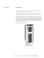
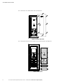
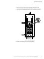
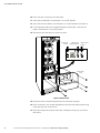
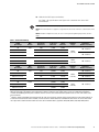
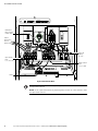
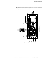
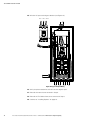
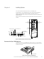
Powerware Series
®
Eaton 9355 Tie Cabinet
Installation Guide
For use with Eaton® 9355 20/30 kVA UPSs
Eaton, Powerware, LanSafe, Powerware Hot Sync, and X-Slot are registered trademarks of Eaton Corporation or its subsidiaries and affiliates.
Greenlee is a registered trademark of Greenlee Textron. National Electrical Code and NEC are registered trademarks of National Fire Protection
Association, Inc. All other trademarks are property of their respective companies.
ECopyright 2006–2010 Eaton Corporation, Raleigh, NC, USA. All rights reserved. No part of this document may be reproduced in any way without
the express written approval of Eaton Corporation.
Class A EMC Statements
FCC Part 15
NOTE This equipment has been tested and found to comply with the limits for a Class A digital device, pursuant to part 15 of the FCC Rules. These
limits are designed to provide reasonable protection against harmful interference when the equipment is operated in a commercial environment.
This equipment generates, uses, and can radiate radio frequency energy and, if not installed and used in accordance with the instruction manual,
may cause harmful interference to radio communications. Operation of this equipment in a residential area is likely to cause harmful interference in
which case the user will be required to correct the interference at his own expense.
ICES-003
This Class A Interference Causing Equipment meets all requirements of the Canadian Interference Causing Equipment Regulations ICES‐003.
Cet appareil numérique de la classe A respecte toutes les exigences du Reglement sur le matériel brouilleur du Canada.
IEC 62040-2
Some configurations are classified under IEC 62040-2 as “Class‐A UPS for Unrestricted Sales Distribution.” For these configurations, the following
applies:
WARNING This is a Class A‐UPS Product. In a domestic environment, this product may cause radio interference, in which case, the user may be
required to take additional measures.
Requesting a Declaration of Conformity
Units that are labeled with a CE mark comply with the following harmonized standards and EU directives:
S
Harmonized Standards: EN 50091-1-1 and EN 50091-2; IEC 60950 Third Edition
S
EU Directives:
73/23/EEC, Council Directive on equipment designed for use within certain voltage limits
93/68/EEC, Amending Directive 73/23/EEC
89/336/EEC, Council Directive relating to electromagnetic compatibility
92/31/EEC, Amending Directive 89/336/EEC relating to EMC
The EC Declaration of Conformity is available upon request for products with a CE mark. For copies of the EC Declaration of Conformity, contact:
Eaton Power Quality Oy
Koskelontie 13
FIN-02920 Espoo
Finland
Phone: +358-9-452 661
Fax: +358-9-452 665 68
Special Symbols
The following are examples of symbols used on the UPS or accessories to alert you to important information:
RISK OF ELECTRIC SHOCK - Observe the warning associated with the risk of electric shock symbol.
CAUTION: REFER TO OPERATOR'S MANUAL - Refer to your operator's manual for additional information, such
as important operating and maintenance instructions.
This symbol indicates that you should not discard the UPS or the UPS batteries in the trash. This product
contains sealed, lead‐acid batteries and must be disposed of properly. For more information, contact your
local recycling/reuse or hazardous waste center.
This symbol indicates that you should not discard waste electrical or electronic equipment (WEEE) in the
trash. For proper disposal, contact your local recycling/reuse or hazardous waste center.
ON - Indicates that the switch is in the ON position.
OFF - Indicates that the switch is in the OFF position.
PHASE - The word “phase.”
Table of Contents
1
Introduction . . . . . . . . . . . . . . . . . . . . . . . . . . . . . . . . . . . . . . . . . . . . . . . . . . . . . . . .
1
2
Safety Warnings . . . . . . . . . . . . . . . . . . . . . . . . . . . . . . . . . . . . . . . . . . . . . . . . . . . .
3
3
Tie Cabinet Installation . . . . . . . . . . . . . . . . . . . . . . . . . . . . . . . . . . . . . . . . . . . . . . .
7
4
Installing Options . . . . . . . . . . . . . . . . . . . . . . . . . . . . . . . . . . . . . . . . . . . . . . . . . . .
19
Powerware Hot Sync® CAN Bridge Card . . . . . . . . . . . . . . . . . . . . . . . . . . . . . . . . . . . . . . . . . . . . . . . . . . .
19
5
Service and Support . . . . . . . . . . . . . . . . . . . . . . . . . . . . . . . . . . . . . . . . . . . . . . . . .
27
6
Warranty . . . . . . . . . . . . . . . . . . . . . . . . . . . . . . . . . . . . . . . . . . . . . . . . . . . . . . . . . .
29
Limited Factory Warranty . . . . . . . . . . . . . . . . . . . . . . . . . . . . . . . . . . . . . . . . . . . . . . . . . . . . . . . . . . . . . .
29
Eaton 9355 Tie Cabinet (20/30 kVA) Installation Guide S 164201630 Rev B www.eaton.com/powerquality
i
TABLE OF CONTENTS
ii
Eaton 9355 Tie Cabinet (20/30 kVA) Installation Guide S 164201630 Rev B www.eaton.com/powerquality
Chapter 1
Introduction
A Tie Cabinet can be installed as a wall-mounted bypass or to provide support for a
parallel system for redundancy or extra capacity.
A wall-mounted bypass switch is used to bypass the UPS during maintenance or
servicing, providing wrap-around bypass for UPS service without shutting down the
load.
A parallel (load sharing) system provides more capacity than a single UPS and can
provide backup, depending on the load and configuration. In addition, when one UPS
is taken out of service for maintenance or is not operating properly, a redundant UPS
continues to supply uninterrupted power to the critical load. A parallel Powerware Hot
Sync® CAN Bridge Card provides connectivity for system metering and operational
mode control. The parallel system consists of two to four UPSs, each with a parallel
CAN Bridge Card and a parallel cabinet.
Figure 1 shows the Eaton 9355 UPS.
Figure 1. The Eaton 9355 UPS
Eaton 9355 Tie Cabinet (20/30 kVA) Installation Guide S 164201630 Rev B www.eaton.com/powerquality
1
INTRODUCTION
2
Eaton 9355 Tie Cabinet (20/30 kVA) Installation Guide S 164201630 Rev B www.eaton.com/powerquality
Chapter 2
Safety Warnings
IMPORTANT SAFETY INSTRUCTIONS
SAVE THESE INSTRUCTIONS
This manual contains important instructions that you should follow during installation and maintenance of
the UPS and batteries. Please read all instructions before operating the equipment and save this manual for
future reference.
DANGER
This UPS contains LETHAL VOLTAGES. All repairs and service should be performed by AUTHORIZED
SERVICE PERSONNEL ONLY. There are NO USER SERVICEABLE PARTS inside the UPS.
WARNING
S This UPS contains its own energy source (batteries). The UPS output may carry live voltage even when
the UPS is not connected to an AC supply.
S To reduce the risk of fire or electric shock, install this UPS in a temperature and humidity controlled,
indoor environment, free of conductive contaminants. Ambient temperature must not exceed 40°C
(104°F). Do not operate near water or excessive humidity (95% maximum).
S To reduce the risk of fire, connect only to a circuit provided with 125 amperes maximum branch circuit
overcurrent protection in accordance with the National Electrical Code, ANSI/NFPA 70.
S Output overcurrent protection and disconnect switch must be provided by others.
CAUTION
S Batteries can present a risk of electrical shock or burn from high short circuit current. Observe proper
precautions. Servicing should be performed by qualified service personnel knowledgeable of batteries
and required precautions. Keep unauthorized personnel away from batteries.
S Proper disposal of batteries is required. Refer to your local codes for disposal requirements.
S Never dispose of batteries in a fire. Batteries may explode when exposed to flame.
Eaton 9355 Tie Cabinet (20/30 kVA) Installation Guide S 164201630 Rev B www.eaton.com/powerquality
3
SAFETY WARNINGS
Consignes de Sécurité
CONSIGNES DE SÉCURITÉ IMPORTANTES
CONSERVER CES INSTRUCTIONS
Ce manuel comporte des instructions importantes que vous êtes invité à suivre lors de toute procédure
d'installation et de maintenance des batteries et de l'onduleur. Veuillez consulter entièrement ces
instructions avant de faire fonctionner l'équipement et conserver ce manuel afin de pouvoir vous y reporter
ultérieurement.
DANGER!
Cet onduleur contient des TENSIONS MORTELLES. Toute opération d'entretien et de réparation doit être
EXCLUSIVEMENT CONFIÉE A UN PERSONNEL QUALIFIÉ AGRÉÉ. AUCUNE PIÈCE RÉPARABLE PAR
L'UTILISATEUR ne se trouve dans l'onduleur.
AVERTISSEMENT!
S Cette onduleur possède sa propre source d'alimentation (batteries). Il est possible que la sortie de
l'onduleur soit sous tension même lorsque l'onduleur n'est pas connectée à une alimentation CA.
S Pour réduire les risques d'incendie et de décharge électrique, installer l'onduleur uniquement à
l'intérieur, dans un lieu dépourvu de matériaux conducteurs, où la température et l'humidité ambiantes
sont contrôlées. La température ambiante ne doit pas dépasser 40 °C. Ne pas utiliser à proximité d'eau
ou dans une atmosphère excessivement humide (95 % maximum).
S Afin de réduire les risques d'incendie, n'effectuez le raccordement qu'avec un circuit muni d'une
protection de surintensité du circuit de dérivation maximum de 125 ampères conformément au Code
Électrique National (National Electrical Code) des États-Unis ANSI/NFPA 70.
S La protection de surintensité de sortie ainsi que le sectionneur doivent être fournis par des tiers.
ATTENTION!
S Les batteries peuvent présenter un risque de choc électrique ou de brûlure provenant d'un courant de
court-circuit haute intensité. Observez les précautions appropriées. L'entretien doit être réalisé par du
personnel qualifié connaissant bien les batteries et les précautions nécessaires. N'autorisez aucun
personnel non qualifié à manipuler les batteries.
S Une mise au rebut réglementaire des batteries est obligatoire. Consulter les règlements en vigueur dans
votre localité.
S Ne jamais jeter les batteries au feu. L'exposition aux flammes risque de les faire exploser.
4
Eaton 9355 Tie Cabinet (20/30 kVA) Installation Guide S 164201630 Rev B www.eaton.com/powerquality
SAFETY WARNINGS
Advertencias de Seguridad
INSTRUCCIONES DE SEGURIDAD IMPORTANTES
GUARDE ESTAS INSTRUCCIONES
Este manual contiene instrucciones importantes que debe seguir durante la instalación y el mantenimiento
del SIE y de las baterías. Por favor, lea todas las instrucciones antes de poner en funcionamiento el equipo y
guarde este manual para referencia en el futuro.
PELIGRO
Este SIE contiene VOLTAJES MORTALES. Todas las reparaciones y el servicio técnico deben ser efectuados
SOLAMENTE POR PERSONAL DE SERVICIO TÉCNICO AUTORIZADO. No hay NINGUNA PARTE QUE EL
USUARIO PUEDA REPARAR dentro del SIE.
ADVERTENCIA
S Este SIE contiene su propia fuente de energía (baterías). La salida del SIE puede transportar voltaje
activo aun cuando el SIE no esté conectado con una fuente de CA.
S Para reducir el riesgo de incendio o de choque eléctrico, instale este SIE en un lugar cubierto, con
temperatura y humedad controladas, libre de contaminantes conductores. La temperatura ambiente no
debe exceder los 40°C. No trabaje cerca del agua o con humedad excesiva (95% máximo).
S Para reducir el riesgo de incendio, realice la conexión únicamente hacia un circuito que cuente con un
máximo de 125 amperios de protección contra sobrecorriente de circuito derivado, de acuerdo con el
Código Eléctrico Nacional, ANSI/NFPA 70.
S La protección contra sobrecorriente de salida y el conmutador de desconexión debe suministrarse por
parte de terceros.
PRECAUCIÓN
S Las baterías pueden constituir un riesgo de descarga eléctrica o quemaduras por corriente alta de corto
circuito. Adopte las precauciones debidas. Personal calificado de servicio que conozca de baterías y esté
al tanto de las precauciones requeridas debe darle servicio al equipo. Mantenga al personal no
autorizado alejado de las baterías.
S Es necesario desechar las baterías de un modo adecuado. Consulte las normas locales para conocer los
requisitos pertinentes.
S Nunca deseche las baterías en el fuego. Las baterías pueden explotar si se las expone a la llama.
Eaton 9355 Tie Cabinet (20/30 kVA) Installation Guide S 164201630 Rev B www.eaton.com/powerquality
5
SAFETY WARNINGS
6
Eaton 9355 Tie Cabinet (20/30 kVA) Installation Guide S 164201630 Rev B www.eaton.com/powerquality
Chapter 3
Tie Cabinet Installation
The Eaton 9355 has the following power connections:
S 3‐phase (L1, L2, and L3), neutral, and ground connection for rectifier/bypass input
S 3‐phase (L1, L2, and L3), neutral, and ground connection for load output
The nominal input/output voltages are:
S 120/208 or 127/220 Vac
Output overcurrent protection and disconnect switch must be provided by others.
Figure 9 and Figure 11 beginning on page 15 show the oneline diagrams.
WARNING
Only qualified service personnel (such as a licensed electrician) should perform the UPS installation and
initial startup. Risk of electrical shock.
To hardwire the Tie Cabinet:
1.
Verify that the electrical connections to the installation site have been properly
installed.
2.
A wall-mounted, user‐supplied, readily‐accessible disconnection device must be
incorporated in the input wiring.
Compare the circuit breaker ratings to the ones in Table 1 on page 11.
NOTE To accommodate the feature of easy system expandability, it is recommended that initial
installation of the Eaton 9355 UPS contain wiring to support the maximum capacity of the UPS cabinet.
3.
Switch off utility power to the distribution point where the Tie Cabinet and UPSs
will be connected. Be absolutely sure there is no power.
4.
Determine your equipment's grounding requirements according to your local
electrical code.
Eaton 9355 Tie Cabinet (20/30 kVA) Installation Guide S 164201630 Rev B www.eaton.com/powerquality
7
TIE CABINET INSTALLATION
5.
Remove the Tie Cabinet front cover (see Figure 2).
Figure 2. Tie Cabinet Front Cover
6.
Remove the internal covers to gain access to the breakers (see Figure 3).
Figure 3. Internal Covers
8
Eaton 9355 Tie Cabinet (20/30 kVA) Installation Guide S 164201630 Rev B www.eaton.com/powerquality
TIE CABINET INSTALLATION
7.
Punch holes for the conduit (AC input, UPS output, load connection, and
maintenance bypass contact wires) using a Greenlee® punch or similar device.
8.
Verify that the Tie Cabinet bypass breaker is in the OFF position (see Figure 4).
Figure 4. Tie Cabinet Bypass Breaker
9.
Mount the Tie Cabinet to the wall and install the conduit.
Eaton 9355 Tie Cabinet (20/30 kVA) Installation Guide S 164201630 Rev B www.eaton.com/powerquality
9
TIE CABINET INSTALLATION
10. From each UPS, remove the UPS front door.
11. Verify that the UPS input circuit breaker is in the OFF position.
12. Verify that each UPS battery circuit breaker is in the OFF position (see Figure 5).
13. If you ordered the UPS with the optional output circuit breaker, verify that the
output circuit breaker is in the OFF position.
14. Remove the UPS wiring access cover and retain.
Input Circuit
Breaker
Output Circuit
Breaker (optional)
Battery Circuit
Breaker
Wiring Access
Cover
Figure 5. UPS Front View
15. Remove the UPS conduit landing box from the rear panel and retain.
16. Punch two holes in the conduit landing box for the input and output conduit using
a Greenlee punch or similar device.
17. Route the wiring from the back of the UPS, through the wiring tray, to the front
of the UPS.
10
Eaton 9355 Tie Cabinet (20/30 kVA) Installation Guide S 164201630 Rev B www.eaton.com/powerquality
TIE CABINET INSTALLATION
18. Hardwire the UPS input terminations.
See Table 1 for specifications and Figure 6 for a detailed view of the UPS
terminal block.
NOTE Input neutral must be wired for proper operation or the UPS will not start.
NOTE The Eaton 9355 UPS is shipped as a single-feed UPS and can be converted to a dual-feed UPS in the
field.
NOTE DO NOT overtighten the screws; be sure to use the specified tightening torque values shown in
Table 1.
Table 1. Terminal Block Wiring
20 kVA
Input Voltage
Wire
Function
Input Circuit
Breaker Size
L1, L2, L3, N
Wire Size1
Ground
Wire Size1
208
Input
100A
1 AWG
6 AWG
220
100A
1 AWG
6 AWG
480 (with transformer)
45A
8 AWG
10 AWG
600 (with transformer)
35A
8 AWG
10 AWG
1 AWG
6 AWG
220
1 AWG
6 AWG
480 (with transformer)
1 AWG
6 AWG
208
Output
30 kVA
Input Voltage
Wire
Function
Input Circuit
Breaker Size
L1, L2, L3, N
Wire Size1
Ground
Wire Size1
208
Input
125A
1/0 AWG
6 AWG
220
125A
1/0 AWG
6 AWG
480 (with transformer)
60A
6 AWG
10 AWG
600 (with transformer)
50A
8 AWG
10 AWG
1/0 AWG
6 AWG
220
1/0 AWG
6 AWG
480 (with transformer)
1/0 AWG
6 AWG
208
Output
Tightening
Torque
Conduit Size2, 3
(Number of Conduits)
2.00” Conduit (1)
120 lb in
(13.5 Nm)
1.00” Conduit (1)
120 lb in
(13.5 Nm)
2.00” Conduit (1)
Tightening
Torque
Conduit Size2, 3
(Number of Conduits)
2.00” Conduit (1)
120 lb in
(13.5 Nm)
2.00” Conduit (1)
1.00” Conduit (1)
1.00” Conduit (1)
120 lb in
(13.5 Nm)
2.00” Conduit (1)
1 Use only 90°C-rated copper wire. Minimum wire size is based on 120/208 full load ratings applied to NEC Code Table 310‐16. Code may require a larger
AWG size than shown in this table because of temperature, number of conductors in the conduit, or long service runs. Follow local requirements.
2 Per NEC article 300‐20(a), all three-phase conductors must be run in the same conduit. Neutral and ground must be run in the same conduit as the
phase conductors.
3 Conduit is sized to accommodate one neutral conductor the same size as the phase conductor and one ground conductor. If two neutral conductors or
an oversized neutral conductor are to be installed, check the size of the conduit needed to accommodate the extra wire or size and use that conduit
size in place of the conduit size listed. Conduit sizes were chosen from NEC Table C1, type letters RHH, RHW, RHW‐2, TW, THW, THHW, THW‐2.
Eaton 9355 Tie Cabinet (20/30 kVA) Installation Guide S 164201630 Rev B www.eaton.com/powerquality
11
TIE CABINET INSTALLATION
Maintenance
Bypass Auxiliary
Contacts (TB4)
Jumpers
(remove three
wires for
dual-feed)
TB4
Remote DC
(battery)
DC +, DC –
Input Terminal
Block
L1, L2, L3, N, N
Output Terminal
Block
L1, L2, L3, N, N
Ground
Figure 6. UPS Terminal Block
NOTE The two input neutral terminals are jumpered together; use either one of these terminals to make
the input neutral connection.
NOTE The two output neutral terminals are jumpered together; use either one of these terminals to make
the output neutral connection.
12
Eaton 9355 Tie Cabinet (20/30 kVA) Installation Guide S 164201630 Rev B www.eaton.com/powerquality
TIE CABINET INSTALLATION
19. Hardwire the output terminations from the UPS to the Tie Cabinet (see Figure 7).
20. Repeat Steps 11 through 19 for each UPS.
Neutral
Ground
Line 1
Line 2
Line 3
Figure 7. UPS Output to Tie Cabinet Wiring
Eaton 9355 Tie Cabinet (20/30 kVA) Installation Guide S 164201630 Rev B www.eaton.com/powerquality
13
TIE CABINET INSTALLATION
21. Hardwire the load to the Tie Cabinet (see Figure 8).
Maintenance Bypass
Wiring to UPS TB4
Ground
Neutral
Line 1
Line 3
Line 2
Figure 8. Load Connections
14
Eaton 9355 Tie Cabinet (20/30 kVA) Installation Guide S 164201630 Rev B www.eaton.com/powerquality
TIE CABINET INSTALLATION
22. Wire the maintenance bypass auxiliary contacts and terminate to the
maintenance bypass wires in the Tie Cabinet (see Figure 6 on page 12).
Connect the black and the red wire to TB4 on the UPS (see Figure 9). Cap the
blue wire.
NOTE The maintenance bypass contacts are normally-open. To ensure proper bypass operation, DO NOT
use the blue wire (it is normally-closed).
NOTE There are two sets of maintenance bypass wires; you can terminate to either set. If you are
installing four UPSs, it is recommended to terminate two UPSs to one set of wires and two UPSs to the other
set of wires.
Red Wires
(open when breaker is open)
350A Breaker
Auxiliary Contacts
350A
Black Wires
(common)
Blue Wires
(closed when breaker is open)
Bypass Input
110A (4X)
LOAD
From UPS 1 Output
From UPS 2 Output
From UPS 3 Output
From UPS 4 Output
Figure 9. Parallel Wiring Diagram
23. Reinstall the UPS wiring access cover.
24. Reinstall the UPS conduit landing box in the reversed position.
Eaton 9355 Tie Cabinet (20/30 kVA) Installation Guide S 164201630 Rev B www.eaton.com/powerquality
15
TIE CABINET INSTALLATION
25. Wire the AC input to the bypass breaker (see Figure 10).
Line 1 Line 2 Line 3
Figure 10. Bypass AC Input Wiring
26. Verify the phase rotation for each UPS and the bypass input.
27. Reinstall the internal cover removed in Step 6.
28. Reinstall the Tie Cabinet front covers removed in Step 5.
29. Continue to “Installing Options” on page 19.
16
Eaton 9355 Tie Cabinet (20/30 kVA) Installation Guide S 164201630 Rev B www.eaton.com/powerquality
TIE CABINET INSTALLATION
Figure 11. Parallel UPS System with Tie Cabinet Diagram (Single-Feed, 208V or 220V Input : 208V or 220V Output)
Eaton 9355 Tie Cabinet (20/30 kVA) Installation Guide S 164201630 Rev B www.eaton.com/powerquality
17
TIE CABINET INSTALLATION
18
Eaton 9355 Tie Cabinet (20/30 kVA) Installation Guide S 164201630 Rev B www.eaton.com/powerquality
Chapter 4
Installing Options
This section describes the Powerware Hot Sync® CAN Bridge Card.
For other options, such as additional X-Slot® cards, LanSafe® Power Management
Software, remote emergency power-off (REPO), relay output contacts, or
programmable signal inputs, refer to the Eaton 9355 UPS (20/30 kVA) Installation and
Operation Manual.
Figure 12 shows the location of the communication options and control terminals on
the UPS.
X-Slot
Communication
Bay #1
REPO (normally open)
X-Slot
Communication
Bay #2
Control
Terminals
REPO (normally closed)
Signal Input 2
Pull-Chain Output
Contacts (parallel only)
Signal Input 1
DB-9 Communication Port
Relay Output Contacts
Figure 12. Communication Options and Control Terminals
Powerware Hot Sync CAN Bridge Card
®
The Powerware Hot Sync® CAN Bridge Card, shown in Figure 13, can be installed to
provide connectivity for operational mode control and metering of a parallel system at
any UPS in the system.
Plug-in Terminal Block
Figure 13. Powerware Hot Sync® CAN Bridge Card
Eaton 9355 Tie Cabinet (20/30 kVA) Installation Guide S 164201630 Rev B www.eaton.com/powerquality
19
INSTALLING OPTIONS
To install the Powerware Hot Sync® CAN Bridge Card:
1.
Remove the UPS front door.
2.
Remove the communication wiring access plate from the UPS rear panel and
punch a hole in it using a Greenlee punch or similar device (see Figure 14).
3.
Install conduit for the communication wiring.
Communication
Wiring Access Plate
Figure 14. Communication Wiring Access
20
Eaton 9355 Tie Cabinet (20/30 kVA) Installation Guide S 164201630 Rev B www.eaton.com/powerquality
INSTALLING OPTIONS
4.
Set the jumper pins on the Powerware Hot Sync® CAN Bridge Card according to
the parallel configuration (see Figure 15):
S If only two UPSs are paralleled, then set both cards to Pins 1 and 2.
S For three or four paralleled UPSs, set the cards of the first and last UPSs to
Pins 1 and 2; set the cards for the middle UPSs to Pins 2 and 3.
Jumper J7 - Pins 1 and 2
Jumper J7 - Pins 2 and 3
Figure 15. Setting the CAN Bridge Card Jumper J7 (Side View)
5.
Install the CAN Bridge Card into X-Slot 2 (see Figure 12 and Figure 17).
6.
Strip shielded, four-wire, twisted-pair wire (maximum 18 AWG recommended)
for CAN Bridge Card wiring and pull-chain wiring.
7.
Repeat Steps 1 through 6 for each UPS.
Eaton 9355 Tie Cabinet (20/30 kVA) Installation Guide S 164201630 Rev B www.eaton.com/powerquality
21
INSTALLING OPTIONS
8.
Route the wiring through the conduit from the communication wiring access
plate to the opening between the two X-Slot communication bays on each UPS
(see Figure 16).
Figure 16. Routing the Cables
9.
Install the CAN Bridge Card wiring between each UPS (see Figure 18 on
page 25).
Use three wires of the four-wire twisted-pair wire. (Reserve two wires for
pull-chain wiring in Step 11.) Be sure to check correct polarity for Pins 8 and 9:
S Connect SHIELD Pin 10 on all cards together.
S Connect CAN H Pin 9 and CAN L Pin 8 (twisted pair) on all cards together.
22
Eaton 9355 Tie Cabinet (20/30 kVA) Installation Guide S 164201630 Rev B www.eaton.com/powerquality
INSTALLING OPTIONS
10. Route the pull-chain wiring through the middle of the fan section and secure in
the cable clips for each UPS (see Figure 17).
Figure 17. Installing Communication Cables
Eaton 9355 Tie Cabinet (20/30 kVA) Installation Guide S 164201630 Rev B www.eaton.com/powerquality
23
INSTALLING OPTIONS
11. Wire the pull-chain wiring to Signal Input 2 on each UPS and daisy chain the
wiring to each UPS as shown in Figure 18. Be sure to check correct polarity:
S Connect Pull-Chain Output Contact Pin 1 to Signal Input 2 Pin 1 on each UPS.
S Connect Pull-Chain Output Contact Pin 2 to Signal Input 2 Pin 2 on each UPS.
CAUTION
If polarity or wiring is not correct, the parallel system does not operate normally. For example, when shutting
down one UPS, the remaining UPS transfers the load to bypass instead of supporting the load. Verify all CAN
Bridge Card wiring is correct for proper operation.
NOTE Signal Input 2 can still be used for building alarms; it is automatically rerouted to the CAN Bridge
Card.
12. Reinstall the communication wiring access plate on each UPS.
13. Replace the UPS front door on each UPS.
24
Eaton 9355 Tie Cabinet (20/30 kVA) Installation Guide S 164201630 Rev B www.eaton.com/powerquality
INSTALLING OPTIONS
J3
SHIELD 10
CAN H 9
CAN L 8
7
TX
6
TX
5
NO
COM 4
3
NC
ALM RTN2
ALARM 1
J5
To Pull-Chain Contacts
ALARM A
1 LARM 2BPO
X−NP
X44
X45 X52−NC
RS232
X43
PULL CHAIN
OUTP
RELAY OUTPUT
PARALLEL
ONLY
X57
2BPO
ALARM ALARM
1
X−NP
X44
X45 X52−NC
X27
RS232
X43
PULL CHAIN
OUTP
RELAY OUTPUT
PARALLEL
ONLY
X57
ALARM A
1 LARM 2BPO
X−NP
X44
X45 X52−NC
X27
X43
PULL CHAIN
OUTP
RELAY OUTPUT
PARALLEL
ONLY
X57
X27
UPS #1
UPS #2
UPS #3
RS232
From UPS #1
To UPS #3
Signal Input 2
Pull-Chain Output Contacts
Figure 18. CAN Bridge Card and Pull-Chain Wiring
Eaton 9355 Tie Cabinet (20/30 kVA) Installation Guide S 164201630 Rev B www.eaton.com/powerquality
25
INSTALLING OPTIONS
26
Eaton 9355 Tie Cabinet (20/30 kVA) Installation Guide S 164201630 Rev B www.eaton.com/powerquality
Chapter 5
Service and Support
If you have any questions or problems with the UPS, call your Local Distributor or the
Help Desk at one of the following telephone numbers and ask for a UPS technical
representative.
United States:
Canada:
All other countries:
1-800-843-9433 or 1-919-870-3028
1-800-461-9166 ext 260
Call your local service representative
Please have the following information ready when you call for service:
S Model number
S Serial number
S Firmware version number
S Date of failure or problem
S Symptoms of failure or problem
S Customer return address and contact information
Eaton 9355 Tie Cabinet (20/30 kVA) Installation Guide S 164201630 Rev B www.eaton.com/powerquality
27
SERVICE AND SUPPORT
28
Eaton 9355 Tie Cabinet (20/30 kVA) Installation Guide S 164201630 Rev B www.eaton.com/powerquality
Chapter 6
Warranty
Limited Factory Warranty
Three‐Phase Eaton® 9355 UPS Products
WARRANTOR: The warrantor for the limited warranties set forth herein is Eaton Corporation, an Ohio Corporation (“Eaton”).
LIMITED WARRANTY: This limited warranty (this “Warranty”) applies only to the original end-user (the “End-User”) of the Eaton 9355 UPS
Products (the “Product”) and cannot be transferred. This Warranty applies even in the event that the Product is initially sold by Eaton for resale to
an End-User.
WHAT THIS LIMITED WARRANTY COVERS: The warrantor warrants,with the terms of this Warranty, that the Eaton three-phase UPS electronics,
Eaton-built accessories, and Eaton -built battery cabinets (individually and collectively, the ”Warranted Items”) are free from defects in material and
workmanship.
For Product installed (and currently located) in the fifty (50) United States and the District of Columbia, if, in the opinion of Eaton, a Warranted Item
is defective, Eaton's sole obligation, at the option of Eaton, will be to refurbish or replace such defective Warranted Item (including the costs of
providing diagnosis, service, and labor [“labor coverage”]). The defective Warranted Item will be refurbished or replaced onsite at the End-User's
location or such other location as determined by Eaton. Any parts that are replaced may be new or reconditioned. All parts replaced by Eaton shall
become the property of Eaton.
For Product installed (and currently located) outside the fifty (50) United States and the District of Columbia, if, in the opinion of Eaton, a Warranted
Item is defective, Eaton's sole obligation, at the option of Eaton, will be to refurbish or replace such defective Warranted Item (not including the
costs of labor coverage). The defective Warranted Item will be refurbished or replaced onsite at the End-User's location or such other location as
determined by Eaton. Any parts that are replaced may be new or reconditioned. All parts replaced by Eaton shall become the property of Eaton.
LIMITED WARRANTY PERIOD:
The period covered by this Warranty for Product installed (and currently located) in the fifty (50) United States and the District of Columbia is ninety
(90) days from the date of Product purchase for labor coverage and twelve (12) months from the date of Product purchase or eighteen (18) months
from the date of Product shipment, whichever occurs first, for the refurbishment/replacement of parts.
The period covered by this Warranty for Product installed (and currently located) outside the fifty (50) United States and the District of Columbia is
ninety twelve (12) months from the date of Product purchase or eighteen (18) months from the date of Product shipment, whichever occurs first,
for the refurbishment/replacement of parts.
WHAT THIS LIMITED WARRANTY DOES NOT COVER: This Warranty does not cover any defects or damages caused by: (a) failure to properly
store the Product before installation, including the ”trickle charge” of batteries no later than the date indicated on the packaging; (b) shipping and
delivery of the Product if shipping is FOB Factory; (c) neglect, accident, fire, flood, lightning, vandalism, acts of God, Customer's neglect, abuse,
misuse, misapplication, incorrect installation; (d) repair or alteration not authorized in writing by Eaton personnel or performed by an authorized
Eaton Customer Service Engineer or Agent; or (e) improper testing, operation, maintenance, adjustment, or any modification of any kind not
authorized in writing by Eaton personnel or performed by an authorized Eaton Customer Service Engineer or Agent.
This Warranty is not valid: if the Product's serial numbers have been removed or are illegible. Any Warranted Items repaired or replaced pursuant
to this Warranty will be warranted for the remaining portion of the original Warranty subject to all the terms thereof. Labor warranty is not provided
for Product located outside of the fifty (50) United States or the District of Columbia. Any equipment, parts, or materials included in the Product
and not manufactured by Eaton are warranted solely by the manufacturer of such equipment, parts, or materials and are not included as part of
this Warranty. Batteries are not warranted by Eaton.
THIS WARRANTY IS THE END-USER'S SOLE REMEDY AND IS EXPRESSLY IN LIEU OF, AND THERE ARE NO OTHER EXPRESSED OR IMPLIED
GUARANTEES OR WARRANTIES (INCLUDING ANY IMPLIED WARRANTY OF MERCHANTABILITY OR FITNESS FOR ANY PURPOSE, WHICH ARE
EXPRESSLY DISCLAIMED).
LIMITATION OF LIABILITY: In no event shall Eaton be liable for any indirect, incidental, special, or consequential damages of any kind or type
whatsoever, or based on any claim or cause of action, however denominated. Eaton shall not be responsible for failure to provide service or parts
due to causes beyond Eaton's reasonable control. In no case will Eaton's liability under this Warranty exceed the replacement value of the
Warranted Items.
END-USER'S OBLIGATIONS: In order to receive the benefits of this Warranty, the End-User must register the product warranty (via mail or online
at www.eaton.com/PQ/Register); use the Product in a normal way; follow the Product's user's guide; and protect against further damage to the
Product if there is a covered defect.
OTHER LIMITATIONS: Eaton's obligations under this Warranty are expressly conditioned upon receipt by Eaton of all payments due to it (including
interest charges, if any). During such time as Eaton has not received payment of any amount due to it for the Product, in accordance with the
contract terms under which the Product is sold, Eaton shall have no obligation under this Warranty. Also during such time, the period of this
Warranty shall continue to run and the expiration of this Warranty shall not be extended upon payment of any overdue or unpaid amounts.
Eaton 9355 Tie Cabinet (20/30 kVA) Installation Guide S 164201630 Rev B www.eaton.com/powerquality
29
WARRANTY
COSTS NOT RELATED TO WARRANTY: The End-User shall be invoiced for, and shall pay for, all services not expressly provided for by the terms of
this Warranty, including without limitation site calls involving an inspection that determines no corrective maintenance is required. Any costs for
replacement equipment, installation, materials, freight charges, travel expenses, or labor of Eaton representatives outside the terms of this
Warranty will be borne by the End-User.
OBTAINING WARRANTY SERVICE: In the USA, call the Eaton Customer Reliability Center 7x24 at 800-843-9433. Outside of the USA, call your
local Eaton sales or service representative. For comments or questions about this Limited Factory Warranty, write to the Customer Quality
Representative, 3301 Spring Forest Road, Raleigh, North Carolina 27616 USA.
30
Eaton 9355 Tie Cabinet (20/30 kVA) Installation Guide S 164201630 Rev B www.eaton.com/powerquality
*164201630B*
164201630 B