1
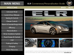
January 2014, Volume 16, No. 1 The 2014 Cadillac ELR The 2014 Cadillac ELR is a sleek luxury coupe that features the first application of Extended Range Electric Vehicle (EREV) technology by a full-line luxury automotive brand. EREV technology provides an EV range of approximately 37 miles (60 km) and a full driving range of approximately 340 miles (547 km) by combining pure electric driving and a rangeextending 1.4L gas powered generator. Top speed is 106 mph (170 km/h). Uncompromising performance is delivered with 295 lb-ft of torque (400 Nm), more than the 3.6L V-6 in the SRX. MODES OF OPERATION 2014 Cadillac ELR. . . . . . . . . . . . . . . . . . . . . . . . . . . . 1 In the primary electric mode, the ELR is powered by its high voltage propulsion battery, until the battery is depleted to a predetermined level. After that, the ELR uses a range-extending 1.4L gas powered generator that produces enough energy to power it for hundreds of miles on a single tank of gas. With colder outside temperatures, the e nergy needed to warm the vehicle’s cabin and high voltage propulsion battery can cause the vehicle’s electric range to decline. Contents Cold Weather EV Electric Range Tips. . . . . . . . . . . . . 3 Charging the ELR . . . . . . . . . . . . . . . . . . . . . . . . . . . . 4 Tire Noise Diagnosis. . . . . . . . . . . . . . . . . . . . . . . . . . 5 Instrument Cluster Not Displaying Data. . . . . . . . . . . 5 Unable to Rotate the Ignition Key. . . . . . . . . . . . . . . . 5 Climate Control and Heated/ Cooled Seat Operation during a Remote Start . . . . . . . . . . . . . . . . 6 A green efficiency gauge indicates efficient driving. The distance the ELR can be driven in primary electric mode is greatly affected by driving style. Observing the green Efficiency Gauge in the instrument cluster can minimize aggressive and inefficient acceleration or d eceleration. Passenger Air Bag and Safety Belt Indicator Information. . . . . . . . . . . . . . . . . . . . . . . . . . 6 EBCM DTC Set in History. . . . . . . . . . . . . . . . . . . . . .6 Tool Room Organization . . . . . . . . . . . . . . . . . . . . . . . 7 DTC P0300 Setting after Engine Repairs . . . . . . . . . . 7 2014 Caprice PPV. . . . . . . . . . . . . . . . . . . . . . . . . . . . 8 Cold Weather Tire Pressure Monitor System Tips . . . 9 Electric range is maximized at 50 mph (80 km/h) and below. Higher speeds use more energy and can significantly reduce electric range. Total vehicle range is based on the available combined electric and extended range. Tailgate Pop Noise . . . . . . . . . . . . . . . . . . . . . . . . . . 10 TIP: The high voltage propulsion battery pack will not be recharged while in extended range mode. To recharge the battery pack completely, the vehicle must be plugged in. Car Issues – Fix It Right the First Time. . . . . . . . . . . 11 Key Off Radio Operation. . . . . . . . . . . . . . . . . . . . . . 10 EBCM Scan Tool Communication. . . . . . . . . . . . . . . 10 Truck Issues – Fix It Right the First Time. . . . . . . . . . 11 Service Know-How . . . . . . . . . . . . . . . . . . . . . . . . . . 11 Regenerative Braking When the vehicle is coasting or braking, the power inverter module may operate the drive motor as a generator, exerting a driveline load that helps to slow the vehicle. The electrical continued on page 2 Customer Care and Aftersales 2014 Cadillac ELR – continued from page 1 Internal Combustion Engine (ICE) Starting energy that the drive motor creates is transferred by the power inverter module to the battery pack. Constant communication between the power inverter module and the Electronic Brake Control Module allows the blending of regenerative braking force with hydraulic braking force. Instead of a 12 V starter motor, a much more powerful 300 V Drive Motor A, located within the transmission, is utilized to crank the engine. Drive Motor A can rotate the engine to operating speed of 800 RPM within just a few hundred milliseconds, allowing near-instant starting. The vehicle’s on-board computers determine when the engine needs to run: Regen on Demand Regen on Demand will slow the vehicle by recapturing energy. It works in Drive and Low. To activate Regen on Demand, pull and hold either paddle on the back of the steering wheel without pressing the brake pedal or accelerator pedal. Regen on Demand is deactivated once the paddles are released, or the brake pedal or accelerator pedal is pressed. Cruise control will turn off, and the brake lights may turn on, when this feature is activated. •The hybrid/EV battery pack has a low state of charge. •The hood is open or not completely latched. •The engine is needed to maintain the high voltage battery pack temperature. •The engine needs to run for maintenance. •Low ambient temperatures. At temperatures of 35°F (2°C) and colder, the engine can run to provide both electric power and heat to supplement the electric heater. This can happen regardless of battery charge level. TIP: Regen on Demand will not stop the car. HIGH VOLTAGE LITHIUM-ION DRIVE MOTOR BATTERY SYSTEM Service Mode The heart of the ELR's electric propulsion system is its advanced Lithium-Ion Drive Motor Battery System. The hybrid battery contains 288 cells, organized into three battery sections, with a nominal system voltage of 355 V direct current. Service Mode is available for service and diagnostics and to verify the proper operation of the MIL and may be required for emission inspection purposes. With the vehicle off and the brake pedal not applied, pressing and holding the POWER button for more than 5 seconds will place the vehicle in Service Mode. The vehicle will not be able to be driven. The propulsion system will not start in Service Mode. The battery energy control module monitors the voltage of the battery cells through four hybrid battery interface control modules. The battery is liquid cooled for long life and optimum performance. Transmission The high voltage battery is located beneath the vehicle. The battery energy control module, battery interface control modules 1-4, current sensor, The hybrid battery is organized into three and high voltbattery sections beneath the vehicle. age contactors are located within the battery assembly. The Powertrain Control Module 2 (the host controller for Diagnostic Trouble Code information) is located under the front passenger seat. The 4ET50 (RPO MKA) is a fully automatic electronically controlled transmission. It consists primarily of a torque dampener assembly, an integral main and auxiliary fluid pump and housing, one planetary gear set, three clutch assemblies, a hydraulic pressurization and control system, and two internal electric motors. Drive motor generator A is 55 kW and drive motor generator B is 135 kW. The planetary gear set provides the electrically variable forward mode ratios and reverse. The TCM and the drive motor generator power inverter module vary the torque output at the optimum time based on throttle position. The main hydraulic system primarily consists of a gerotor-type pump, control valve body assemblies, dampener housing and case. A secondary auxiliary pump with electric three phase high voltage motor located inside the transmission maintains working pressures when the engine is off. TIP: Before performing service, ensure all High Voltage Safety procedures and Warnings are followed exactly as written. Personal Protection Equipment (PPE) MUST be worn and proper procedures MUST be followed. ELECTRICAL ARCHITECTURE The Manual Service Disconnect (MSD) is located under the front floor console rear trim panel. Removing the rear trim panel will expose the MSD. The 2014 ELR uses GM’s Global A electrical architecture. This architecture requires the use of the Global Diagnostic System 2 (GDS 2) software and the Multiple Diagnostic Interface (MDI) module. Drive Motor Battery Charging AGM 12V Battery The lithium-ion high voltage battery pack can be charged using the provided charging cord and a 120-volt standard outlet. Charge times will vary with outside temperature. The ELR uses an Absorbent Glass Mat (AGM) 12 V battery that requires different charging voltages than conventional lead acid batteries. The essential tool (GR-8) EL-50313 has this algorithm built in. Select AGM when prompted or damage to the battery will result. Charging Status Indicators are located on the instrument panel near the windshield and in the side mirrors (if activated). DRIVETRAIN The ELR uses the 12 V battery to wake up and initialize control modules. If the vehicle does not power up, verify that the 12 V battery is sufficiently charged to allow all of the control modules to wake up. continued on page 3 The underhood gas powered electric generator is a 1.4L DOHC inline four cylinder engine that produces 83 HP (62 kW). Premium gasoline with a posted octane rating of 91 or higher is required. 2 January 2014 Cold Weather EV Electric Range Tips As temperatures fall, it’s important to remind Chevrolet Volt and Cadillac ELR owners that the electric range of their vehicle can be affected. During colder months, the energy needed to warm the vehicle’s cabin and high-voltage battery can cause the electric range to decline. mode setting from Comfort to Eco to help reduce the energy used to heat the cabin. If equipped, use the automatic heated seats to keep warm. The heated seats use less energy than heating the entire cabin. To help maximize electric vehicle (EV) electric range during cold weather, follow these tips. They can help Volt and ELR owners in all climates increase their vehicle’s efficiency. As the outside temperature drops, the air pressure in the tires drops as well. Check the tire pressure and add more air if needed to maintain the tire pressures at the recommended level. Recommended tire pressure is on the Tire and Loading Information label inside the driver’s door opening. Properly inflated tires can help improve electric range and fuel economy. Precondition while Plugged-In Take advantage of the power of the grid to heat the cabin and the high-voltage battery prior to driving. The Volt and ELR can be remote started several ways while plugged in, including using the key fob or the OnStar RemoteLink app available on compatible smartphones and tablets. Using energy from the grid to warm the cabin enables the stored battery energy to be reserved for driving. Maximum benefit is provided when using a 240V charger. Keeping Warm on the Road To maximize electric range, set the climate Check Tire Pressures Engine-Assisted Heating On 2013-2014 Volt and 2014 ELR only, this feature enables owners to select the outside temperature level at which the gas-powered generator will run to assist heating while driving in Electric Mode. The Engine-Assisted Heating options are: •At Cold Outside Temperatures, below approximately 35°F (2°C). This selection maximizes the battery range and uses a very small amount of gasoline to help 2014 Cadillac ELR – power the vehicle during cold temp eratures. •At Very Cold Outside Temperatures, below approximately 15°F (−10°C). This selection uses less gasoline, but has a larger adverse impact on battery range. Three T’s Remind customers of the three T’s to maximizing electric range. Temperature – Cold weather will adversely impact electric range, but efficient use of the climate system and prewarming the vehicle while it is plugged in can help reduce the effect of cold outside temperatures on electric range. Terrain – Going up and down hills is less efficient than driving on flat surfaces. Where possible, avoid hilly routes to maximize electric range. Technique – Aggressive acceleration and deceleration are not as efficient as smooth, easy starts and stops. Use the efficiency gauge in the instrument cluster to help drive more efficiently. Thanks to Keith Newbury continued from page 2 If the vehicle’s 12 V battery is weak or disconnected, the door handle touch pads and door latch buttons may not operate. The doors can be opened from the outside manually by opening the trunk with the door key and pulling the door release tab below the package shelf. UNIQUE FEATURES Heating and Air Conditioning The heating system uses a high voltage heater when the engine is not running and passenger compartment heat is requested. The HVAC control module monitors the temperature sensors in the passenger compartment, outside air, engine radiator, high voltage heater and the engine to determine the position of the coolant flow control valve and if the high voltage heater is needed. The 300 V electric A/C compressor is a self contained high voltage inverter, electric motor, and direct coupled compressor. It can provide cooling even when the engine is not running. The pulse width modulated electric A/C compressor runs at a speed necessary to maintain a desired cooling level rather than cycling the compressor on and off. At high ambient temperatures and high humidity, the driver may notice a unique high-pitched sound from the compressor when the vehicle is stopped or at low speeds. This is considered normal. The A/C compressor is serviced as a unit. Normal Sounds – the electric engine cooling fan, coolant pumps, the air conditioning compressor and the HVAC blower. The drive motor battery cooling system may be operational during charging or when the vehicle is powered down. The electric motor may be heard as the vehicle moves. This is a normal operating characteristic. ELR uses active noise cancelling at all engine speeds. It gathers input from the generator and powertrain, and from three ceilingmounted microphones. The system produces a noise-cancelling signal through the audio system. Hoist Contact Lift Points A low profile lift arms system may be required to avoid unwanted contact with the vehicle's body and structure depending on the lifting equipment being used. Refer to the hoist manufacturer's recommendation. Refer to #PI1141 for further details, including required service training courses and a list of special tools. Proper front hoist contact lift point. Due to the quiet nature of the ELR's propulsion system, certain sounds that otherwise may have been masked will be apparent Thanks to Chuck Wieseckel and Sherman Dixon January 2014 3 Charging the ELR The 2014 Cadillac ELR with its Extended Range Electric Vehicle (EREV) technology provides an EV range of approximately 37 miles (60 km) and a full driving range of approximately 340 miles (547 km), by combining pure electric driving and its range-extending 1.4L gas powered generator. On the side mirror, the light indicators show the progress of the charging event. They are: The lithium-ion high voltage battery pack holds its charge efficiently and has no memory effect, so it doesn’t have to be run down completely before recharging. Keeping the vehicle plugged in, even when fully charged, will keep the battery temperature ready for the next drive. Solid green – Battery is charging; charging is less than half complete Charging Time Fast flashing green – Charging is more than half complete The ELR can be programmed for three charging modes: Immediately upon plug-in; Delayed based on departure time; and Delayed based on electric rate and departure time. Slow flashing green – Charging is nearly complete Using a 120-volt standard outlet will take approximately 12.5 hours to charge the ELR at the 12-amp setting, or 18 hours at the 8-amp default setting. Using a 240-volt charging station will take approximately 5 hours. Charge times will vary with outside temperature. TIP: Before plugging in to any electrical outlet, have a qualified electrician inspect and verify the electrical system (electrical outlet, wiring, junctions and protection devices) for heavyduty service at a 12-amp continuous load. No light – Charge is complete or not charging Charging 1.Place the vehicle in Park. 2.Select the Charging icon at the bottom of the Energy screen on the touch screen. 3.Review the selected Charge Level and Charge Mode. Touch the green text if an increased Charge Level or different Charge Mode is desired. The Charge Level selection automatically returns to the reduced level each time the vehicle is driven. 4.Once the Charge Level and Charge Mode are selected, turn off the vehicle. 5.Remove the charge cord from the trunk and plug it into an electrical outlet. DO NOT PLUG INTO AN EXTENSION CORD. The charge cord indicator on the base of the charge card should be green. Touch the green text to change the Charge Level or Charge Mode. TIP: •Always properly support the charge cord at all times and do not let it hang from the plug or outlet. Touch the green leaf Energy icon on the infotainment touch screen and then touch the Charging icon to view the current Charge Level and Charge Mode status. •Touch the green Charge Level text to select a different charge level. •Touch the green Charge Mode text to select a different charge mode. •Electrical outlets may wear out with normal usage Instrument panel charging status indicator or be damaged over time, making them unsuitable for electric vehicle charging. Charging Status Charging Status Indicators are located on the instrument panel near the windshield and in the side mirrors (if activated in the Vehicle Personalization menu). On the instrument panel, the light indicators are: •Solid green with single horn chirp – Vehicle is plugged in; battery is charging •Check the electrical outlet/plug while charging and discontinue use if the electrical outlet/plug is hot; have the electrical outlet serviced by a qualified electrician. •Slow (long pulse) flashing green with double horn chirp – Vehicle is plugged in; battery charging is delayed 6.Press and release the rear edge of the charge port door, located just in front of the driver’s door, to open the door. Plug the charge cord into the charge port. •Fast (short pulse) flashing green – Vehicle is plugged in; battery is fully charged •Solid yellow – Vehicle is plugged in; not charging Once charging is complete, unplug the charge cord by pressing the plug release button on the cord, unplug the cord from the electrical outlet and properly stow the charge cord. •No light – Vehicle is not plugged in or there is an issue with the charger or outlet •No light and repetitive horn chirps – Electricity was interrupted before charging was completed Side mirror charging status indicator Thanks to Keith Newbury and Sherman Dixon 4 January 2014 Tire Noise Diagnosis If owners comment about noise related to the tires on their vehicle, there are many factors to consider when performing diagnosis. For example, the amount of tire noise may be due to the tire design, a change from one tire brand to another, or vary based on road speed and road surfaces. A tire with an aggressive tread design will tend to be the most noisy. So winter tires often will be more noisy than all-season tires, which have a tendency to be noisier than summer only tires. This is Larger diameter tires with shorter because of the more sidewalls may be perceived to be noisy aggressive tread compared to smaller tires. that is designed to work well on ice and snow covered roads. Different tires also may be noisier on some surfaces than others. In addition, larger diameter tires with shorter sidewalls, popular on many new models today, also may tend to be perceived as noisy, especially when compared with a previous vehicle with smaller tires. Compare Tires Before tires are replaced for a noise condition, they should be compared with a like vehicle with the same tire brand and model to see if there is any other reason for the noise level in the vehicle. If the vehicle with the tire noise concern is similar to other like vehicles, the tires should not be replaced. Under no circumstances should tires ever be replaced for noise levels that are consistent from one vehicle to another. Also, a summer only tire should never be used as a replacement tire to address a noise concern on a vehicle equipped with all-season tires. This can create undesirable handling conditions in icy or snowy weather. Match TPC Specs A second consideration when diag nosing tire noise is the use of aftermarket tires that do not meet the GM Tire Performance Criteria (TPC) TPC spec marked on the tire specification marked on the original equipment tires. The tires on all new production models have a TPC rating number molded on the sidewall. The TPC rating will appear as a 4-digit number preceded by the letters TPC SPEC on the tire wall near the tire size. Non-TPC marked tires may have been installed by the owner or a used vehicle department. The tread noise of the tires is taken into consideration as part of the engineering development and validation of GM vehicles. If the tire performance is changed with the installation of non-TPC aftermarket tires, noise levels may increase considerably. If tire noise is noticed in a vehicle that has a replacement tire installed, another set of tires and wheels from a similar vehicle should be installed to rule out the tires as a source of noise. Noises from some tread designs may sound remarkably similar to wheel bearings or driveline components, especially at lower speeds and with the HVAC and infotainment systems turned off. A replacement tire should have the same TPC specification number as the original equipment tire. This will ensure the same size, the same load range, and the same construction as those originally installed on the vehicle. After diagnosis, if a customer is not satisfied with what is considered to be a normal tire noise level when compared with like vehicles, the customer’s concern should be reviewed with the local DM-Aftersales. Thanks to David MacGillis Instrument Cluster Not Displaying Data Unable to Rotate the Ignition Key The Instrument Panel Cluster on some 2014 Lacrosse models built before December 19, 2013 and 2014 Regal models built before January 21, 2014 may not display radio or phone data. An Audio Off message may be displayed on the Driver Information Center and the right audio steering wheel controls may be inoperative. In addition, the instrument cluster may intermittently display “Sport” mode and other personalization features may return to the factory default setting. On the new 2014 Silverado 1500 and Sierra 1500 trucks, a steering column lock has been incorporated into the ignition key housing assembly as standard equipment. If the steering wheel is turned with the ignition key in the OFF position, it may cause excessive pressure between the lock plate and lock pin. The next time the ignition key is rotated from the OFF to the ON position, it may be difficult to rotate the key. The steering wheel will need to be rotated in either direction (depending on how the locking pin engaged to the locking plate) to alleviate the pressure between the steering column lock pin and lock plate. This will allow the ignition key to rotate from the OFF position. The ignition key may need to be rotated at the same time the steering wheel is being rotated. These instrument cluster conditions may be the result of a reset condition within the Instrument Panel Cluster. New Instrument Panel Cluster software has been released to address these conditions. Use TIS2Web to update the Instrument Panel Cluster calibrations and confirm proper operation. TIP: The updated software only applies to vehicles built before the listed build dates if audio is still present, the radio controls still function, and no current infotainment DTCs are set. This is a normal characteristic of the vehicle. No additional repairs should be made. Thanks to Jim Will Thanks to Christopher Crumb January 2014 5 Climate Control and Heated/Cooled Seat Operation during a Remote Start The following systems on the 2014 Silverado 1500 and Sierra 1500 may operate during a remote vehicle start: •Climate controls on for 10 minutes when the key is turned to Run/On. The rear window defogger indicator will not be illuminated until the key is turned to Run/On. •Rear window defogger Heated Seats •Heated seats During a remote start, the heated seats will turn on (if enabled) to the high setting when the ambient temperature is below •Cooled seats •Heated steering wheel Climate Control (HVAC) Settings During a remote start, the HVAC settings will operate at the previous HVAC settings when the vehicle was last turned off. If the owner desires a certain HVAC setting during a remote start, the HVAC mode, blower and temperature should be set prior to turning off the truck. Rear Window Defogger During a remote start, the rear window defogger will turn on if the outside temperature is 44° F (7° C) or below. It will stay Owners of some 2007-2013 Silverado and Sierra; 2014 Silverado 2500/3500 and Sierra 2500/3500; and 2008-2009 Hummer H2 models may question if their vehicle should have the following options: •Passenger air bag On/Off indicators = YES, located in the overhead console •Passenger Presence System (PPS) •Passenger safety belt indicator = NO •Passenger air bag On/Off switch •Passenger air bag On/Off switch = YES, located in the lower glove box (RPO C99) 2500/3500 Crew Cab Models •Passenger safety belt indicator •Passenger Presence System (PPS) = NO, Not available This information does not apply to the new 2014 Silverado 1500 and Sierra 1500. •Passenger air bag On/Off indicators = NO The following information outlines the content of each model. •Passenger air bag On/Off switch = NO, Not available 1500 All Models •Passenger safety belt indicator = NO •Passenger Presence System (PPS) = YES, standard equipment (RPO AL0) Hummer H2 •Passenger air bag On/Off indicators = YES, located in the overhead console •Passenger air bag On/Off switch = NO •Passenger safety belt indicator = YES, located in the overhead console 2500/3500 Regular and Extended Cab Models •Passenger Presence System (PPS) = NO, Not available Cooled Seats During a remote start, the cooled seats will turn on (if enabled) to the high setting when the ambient temperature is above 80° F (27° C). They will turn off when the key is turned to Run/On. The cooled seat indicators will not be illuminated when the cooled seats are on during a remote start. To enable the cooled seats to operate during a remote start, go to the Vehicle Settings menu. Heated Steering Wheel Go to the Vehicle Settings menu to enable the heated/cooled seats during a remote start. The seat indicators do not illuminate during a remote start. Passenger Air Bag and Safety Belt Indicator Information •Passenger air bag On/Off indicators 50° F (10° C). They will turn off when the key is turned to Run/On. The heated seat indicators will not be illuminated when the heated seats are on during a remote start. To enable the heated seats to operate during a remote start, go to the Vehicle Settings menu. •Passenger Presence System (PPS) = NO, Not available •Passenger air bag On/Off indicators = YES, located in the overhead console •Passenger air bag On/Off switch = YES, located in the lower glove box (RPO C99) •Passenger safety belt indicator = NO Thanks to Scott Fribranz 6 During a remote start the heated steering wheel does not turn on. Thanks to Jim Will Electronic Brake Control Module DTC Set in History When performing a DTC check using a scan tool on some 2014 Malibu models, the Electronic Brake Control Module (EBCM) may have a DTC C025E SYM5A (Vacuum Sensor Signal Is Not Plausible) set in history. When the DTC is cleared, it may set again and immediately go to history during the next ignition cycle. No messages will be displayed on the Driver Information Center and no Malfunction Indicator Lamps will be illuminated on the instrument cluster. Do not replace any components for this condition. This is a normal operating characteristic. The DTC clears when the diagnostic runs and passes. Thanks to Christopher Crumb January 2014 Tool Room Organization Are you searching for tools instead of working on vehicles? Need an easy way to keep the dealership’s essential tools organized? Without an organized essential tool system, a technician can spend an average of 60 minutes a week looking for the right tools for a repair, which equates to a $60,000 loss per year in billable income. GM 4-Cabinet Essential Tool Storage System (554-GMEST-HV4-2012) The Essential Tool Storage System includes: •A four-cabinet system with 50 drawers and 2 bulk overhead cabinets •A small footprint — the system measures 120”w x 28”d x 94”h •Individual drawer layout sheets show tool location and part/tool number •Storage for 909 required tools (872 in drawers and 37 in overhead cabinets) •An organized system that places each essential tool in a specific location based on its dimensions in order to maximize cabinet storage space and minimize the footprint on the shop floor. 4-Cabinet Essential Tool Storage System GM offers several ways for dealerships to get organized. The GM-authorized Essential Tool Storage System (554-GMEST-HV4-2012) makes it possible to never misplace a tool again instead of spending valuable time digging through piles of tools. Plus, the GM Special Tools Organization website managed by Bosch provides a convenient way to inventory all essential tools as well as check the essential tools that have been released each model year and their applications. The website is available to all GM dealerships at no additional cost as part of their dealership service agreement. In addition to the storage system, several other organization systems are available. Each is designed to help dealerships find the best way to organize and utilize the essential tools that are critical to properly making repairs. For additional information about the GM-authorized Essential Tool Storage System and other storage systems, visit www.gmdesolutions.com or call 1-800-GM-TOOLS. In Canada, contact Dealer Equipment Services (DES) Canada at 1-866-868-3372 or visit www.des-canada.ca. Tool Organization Website The GM Special Tools Organization website managed by Bosch can help dealerships manage their essential tool in- The website provides monthly tool lists and information. ventory, regardless of the type of storage system used in the individual dealership. The website provides quick access to a variety of special tool information: •All monthly essential tool shipment notices are posted by year/month •An electronic catalog lists all GM essential service tools •Essential service tool lists, organized by franchise, are updated monthly •Detailed reports of all essential tools, including tool numbers, applications, tool descriptions, illustrations, and price available in printable reports The GM Special Tools Organization website is accessed via the link provided in GlobalConnect Service Workbench. On the home page for GM Special Service Tools, click the GM Tool Organization link on the left side of the page to log in to the website. (In Canada, go to GlobalConnect Service Library > Tools, Processes and Equipment.) Thanks to Kent Woiak. DTC P0300 Setting after Engine Repairs DTC P0300 (Engine Misfire Detected) may set after performing engine repairs on the following vehicles equipped with a V8 engine: •2002-2014 Silverado HD, Sierra HD •2004-2007 Rainier •2006-2009 Impala SS •2008-2009 LaCrosse, Allure (Canada Only) •2006-2007 Monte Carlo SS •2006-2013 CTS-V •2005-2013 Corvette •2002-2013 Escalade •2003-2010 Hummer H2 •2010-2013 Camaro • 2008-2010 Hummer H3 •2011-2013 Caprice PPV •2002-2013 Avalanche •1999-2013 Express, Silverado, Suburban, Tahoe, Savana, Sierra, Yukon January 2014 •2009-2013 Colorado, Canyon •2003-2009 Trailblazer, Envoy It is possible to have the fuel injector electrical connectors crossed for cylinders 5-7 and 6-8, which may cause an engine misfire. The engine misfire may not be detected and may happen during deceleration. If crossed injector connectors may be a possible cause, follow the appropriate Service Information to validate the injector connector routing. If necessary, correct the injector connector routing and evaluate for proper operation. •2003-2006 SSR • 2008-2010 G8 Thanks to Richard Renshaw • 2005-2006 GTO • 2005-2008 Grand Prix GXP • 2005-2009 Saab 97X 7 2014 Caprice PPV The door lock button has been relocated to the top-rear of the door. Pull the interior door handle once to unlock and pull it again to open the door. In addition, standard trunk release buttons are on both front door interior panels. The auxiliary battery, located in the trunk, has a higher capacity 700 CCA to power accessory equipment. To deliver enhanced performance, electric power steering is standard. The thicker front struts (32 mm instead of 30 mm) and front stabilizer bar (26 mm instead of 24 mm) also provide improved handling. Special Features An auxiliary 110-amp ignition and main power supply wiring harness is located under the lower right side of the instrument panel. One 50-amp battery power circuit and two 30-amp relay controlled circuits are in a five foot coil provided for customer connection. The harness includes signal circuits for ignition power (Hot in Start/Run and Accessory/Run), vehicle radio mute, vehicle speed signal and park-enable. The Chevrolet Caprice Police Patrol Vehicle (PPV) has been equipped with several new features and enhancements for 2014 designed to provide a more tailored fit for law enforcement. These changes include an all-new column-mounted transmission gear selector, which opens up room for a standard steel center console mounting platform for police equipment. Surveillance Mode is standard on the Caprice PPV. The Surveillance Mode circuit is terminated in cavity 1 of the 16 cavity upfitter connector P277, located at the passenger-side front of the equipment mounting platform. New Features The transmission gear selector has been relocated from the center console to the steering column. When Surveillance Mode is activated by applying a ground to the White/Violet wire in cavity 1, all automatic lighting functions are suppressed. All manually operating lighting controls remain functional. If equipped with RPO VVS, Daytime Running Lamps and Automatic Headlamps Disabled, exterior lights are controlled manually. Surveillance Mode suppresses all of the following items: •Radio display is off (audio remains on) •Headlamps and tail lamps are off The new open center conThe Caprice PPV features sole provides a new, open console. space for an equipment mounting platform, which comes installed as standard equipment, and serves as a heavy-duty foundation for a computer and other equipment typically used in police vehicles. •Dome lamps are disabled (inoperative at the lamp switches) •All interior lighting is off •Remote Lock/Unlock audible/visual functions are off RPO 7Y6, Inoperative Dome/Courtesy Lamps, has been deleted for 2014 and replaced by a switch in the front dome lamp assembly. Activate the switch to have the dome lamps remain off when any door is opened, the vehicle is unlocked, or the key is removed from the ignition switch. The all-new instrument panel features an 8-inch Chevrolet MyLink touch screen with Bluetooth® streaming audio, cell phone connectivity, and voice recognition. Applications requiring a USB connection are not compatible. The Caprice PPV does not come equipped with OnStar. Transport Mode The revised front seats provide increased comfort and support for officers wearing a utility belt. Front hip room has increased to 57.5 in. from Auxiliary battery in the trunk. 56.7 in. The front seats have 4-way power seat adjusters and power lumbar adjustment. All 2014 model year vehicles leave the assembly plant with Transport Mode active to save battery power. The Driver Information Center (DIC) will display Transport Mode On when enabled. TIP: The driver’s express power window learn procedure may need to be performed after turning off Transport Mode. When in Transport Mode, the remote function will be inoperative. As the Remote Keyless Entry will not allow remote unlocking of the vehicle, the vehicle will need to be unlocked with the mechanical key. To disable Transport Mode: 1.Turn on the hazard flashers. 2.Apply the brake pedal. 3.Turn the ignition key to the Start position and hold for 15 seconds; continue to depress the brake pedal. 4.Transport Mode Off will display in the DIC when disabled. continued on page 9 8 January 2014 2014 Caprice PPV – continued from page 8 Programming Pre-Delivery Inspection The 2014 Caprice PPV uses the Global A electrical architecture, which requires the use of the GDS 2 for diagnostics. The factoryinstalled rear disc brake rotor protection covers must be removed during the PDI. With the vehicle on a hoist, rotate the wheel while at the same time pulling Remove the brake rotor protection the torn end of covers during PDI. the cover away from the disc brake rotor and wheel. Ensure that all material is removed and repeat for the other side. For programming, the vehicle may be found under the Chevrolet Holden heading. Keys Two keys with Remote Keyless Entry functionality are provided for the Caprice PPV. Options 6E3 or 6E4 are available for police departments requiring a single key for the entire fleet. These common key options provide a single key with a specific code that is common to the door locks and ignition for all the vehicles in the vehicle fleet. They are not compatible with Impala, Tahoe and the previous Caprice police vehicles. TIP: If the engine is running or the key is left in the ignition with the engine off, the Remote Keyless Entry function of a second key cannot be used to operate the door locks. Thanks to Brad Thacher Cold Weather Tire Pressure Monitor System Tips As the temperature drops in the winter months, more customers will see the low tire light on their instrument cluster illuminate indicating low tire pressure. As a rule of thumb, tire pressure will change about 7 kPa (1 psi) for every 10°F (6°C) decrease or increase in temperature; so tire pressure will drop when it gets colder outside and rise when it gets warmer. If the low tire pressure light illuminates, customers that are not familiar with the operation of the Tire Pressure Monitor system in their vehicle may come to the dealership for service. TPM Low Tire Light If the TPM low tire light on the instrument panel is illuminated, determine if the light is due to low tire pressure or if it is the result of a TPM malfunction. the tires. After driving awhile, the tires will heat up, allowing air pressure to increase above the threshold, causing the light to go off. Properly adjust all tire pressures to the recommended levels. •If the low tire light flashes for one minute and then stays on solid (a service tire monitor system message may be displayed on the Driver Information Center), a TPM system condition exists. The vehicle will require further diagnosis. Dashes Indicate System Malfunction specific vehicle corner. When performing a TPM relearn (only after a tire rotation or replacement of a TPM sensor or module), use a scan tool (GDS 2 or the Tech 2), the J-46079 TPM Tester or the EL-50448 TPM Activation Tool to initiate the relearn process and lock out other vehicle TPM signals that may be broadcasting in the area. This method avoids storing false TPM I.D.s and will prevent vehicles from returning with dashes displayed in the tire pressure readouts and/or a flashing low tire light. Check the four TPM I.D.s with a scan tool prior to and following the relearn procedure to verify they are the same. If dashes (---) are displayed in only one or two of the tire pressure readouts, it is likely caused by a previous TPM system relearn that was performed incorrectly due to interference from another vehicle’s TPM system during the relearn process. Each tire monitor sensor is learned to a Turn the key on, without starting the engine: •If the low tire light illuminates and stays on solid (a low tire pressure message may be displayed on the Driver Information Center), tire air pressure is low. Properly adjust all tire air pressures to the recommended levels. Driving the vehicle will turn off the light. •If the low tire light illuminates for a few minutes when the vehicle is started and then goes off after driving, the tire air pressure is likely low in one or more of January 2014 EL-50448 TPM Activation Tool If dashes (---) are displayed in all four of the tire pressure readouts, there is a system condition. Follow the appropriate Service Information procedures. Thanks to Dave MacGillis. J-46079 TPM Tester 9 Tailgate Pop Noise On some 2014 Silverado 1500 and Sierra 1500 models equipped with the EZ Lift and Lower Tailgate (RPO PPA), a pop/snap/click-type noise may be heard when the tailgate is opened. It may sound like the noise is coming from the right-side hinge area. The noise may be caused by the tailgate dampener mounting nut not being torqued properly GM TechLink is published for all GM retail technicians and service consultants to provide timely information to help increase know ledge about GM products and improve the performance of the service department. To correct this condition, inspect the tailgate dampener mounting nut for proper torque. It should be torqued to 25 Nm (18 lb ft) +/- 3 Nm (2 lb ft). Publisher: John Meade GM Customer Care and Aftersales Tailgate dampener mounting nut Thanks to James Will Mark Spencer / [email protected] Some customers may not fully understand the operation of the navigation radio (RPO UYS) with the key off in 2012-2014 Escalade models; 2012-2013 Avalanche, Silverado, Suburban, Tahoe, Sierra, Yukon models; 2013-2014 Express and Savana; 2014 Silverado 2500/3500, Suburban, Tahoe, Sierra 2500/3500, and Yukon models. The radio can be turned back on after the Retained Accessory Power has been canceled by simply pressing the Power button on the radio. If the radio is turned on using this method, opening the driver's door will not turn the radio off. The radio will remain on for about 10 minutes. Lisa G. Scott GM Customer Care and Aftersales Technical Editor: Key Off Radio Operation The radio will work when the ignition key is in the On/Run or Accessory position. Once the key is turned to the Off position, the radio will continue to work for 10 minutes or until the driver's door is opened. This is when the radio is powered by the Retained Accessory Power (RAP). Editor: Production Manager: Marie Meredith Desktop Publishing: 5by5 Design LLC / [email protected] FAX number: 3 1-248-729-4704 Write to: * TechLink PO Box 500 Troy, MI 48007-0500 When the radio turns off after 10 minutes, it can be turned back on by pressing the Power button again. The radio also can be turned off at any time by pressing the Power button. Thanks to Scott Fibranz EBCM Scan Tool Communication The ABS/Traction Control MILs may be illuminated in the instrument cluster on some 2014 Veranos. During diagnosis, the initial scan for diagnostic codes using a scan tool may show that there is a DTC U0415 (Invalid Data Received from Electronic Brake Control Module) stored. It also may not be possible to communicate with the K17 Electronic Brake Control Module (EBCM). Currently, there is an issue with GDS 2 where it is not allowing the scan tool to communicate with the EBCM. For a current work around, it is recommended to build the vehicle as a 2013 model year Verano. This will allow the scan tool to communicate with the EBCM and address any current DTCs that might be stored. GM TechLink on the Web: GM GlobalConnect : General Motors service tips are intended for use by professional technicians, not a “do-it-yourselfer.” They are written to inform those technicians of conditions that may occur on some vehicles, or to provideinformation that could assist in the proper service of a vehicle. Properly trained technicians have the equipment, tools, safety instructions and know-how to do a job properly and safely. If a condition is described, do not assume that the information applies to your vehicle or that your vehicle will have that condition. See a General Motors dealer servicing your brand of General Motors vehicle for information on whether your vehicle may benefit from the information. Inclusion in this publication is not necessarily an endorsement of the individual or the company. Copyright© 2014 General Motors All rights reserved. A correction to this condition is being developed. Thanks to Christopher Hightower 10 January 2014 Car Issues – Fix It Right the First Time Model Year(s) Vehicle Line(s)/Condition Do This Don’t Do This Reference Information/ Bulletin 2013-2014 Volt – Multiple navigation radio screen issues, does not recognize Global Positioning System (GPS), radio screen goes blank, no GPS signal, navigation stuck or will not switch and show correct location Check for loose coaxial connection. Replace radio. PI1100 2014 Spark – A/C inoperable, blows warm air Replace the A/C line, install pressure switch and harness. Replace AC compressor without diagnostics. PI1121 2013 SRX – Heated seat indicator lights momentarily when activated/heated seats inoperative/ DTC U1524 stored Replace the heated seat control module. Replace the center stack or memory seat control module. PI0877A 2013-2014 Volt, Terrain, Malibu, Equinox, Cruze, Camaro, Verano, Regal, Encore, LaCrosse – Radio locks up and/or resets, Bluetooth® pairing, voice recognition and navigation updates Update the radio software through Radio SPS Programming. Replace the radio. PI1114 Truck Issues – Fix It Right the First Time Model Year(s) Vehicle Line(s)/Condition Do This Don’t Do This Reference Information/ Bulletin 2013-2014 Terrain, Equinox – Creak or pop type noise coming from windshield area during cold ambient temperatures Liberally spray lubricant between the outside edge of the windshield glass and trim molding. Replace or reseal the windshield. PI1120 2012-2013 Trax, Encore – Water accumulating in door sill plate area/slosh type noise Punch holes in lower part of weather strip per diagram on each door using similar tool. Replace weather strip. PI1117 2014 Silverado, Sierra – Normal characteristic - Drivers (left) outside rearview mirror takes longer to clear than passenger side Please share the detail information with all involved dealership personnel. Replace mirror, wiring, or controls. PI1106 2013 Encore – Rear brake noise on first apply Install damper on rear caliper. Install brake pads or rotors. PIC5927B 2010 SRX – Creak or pop noise heard from front hub bearing while making turns Check front hub bearing fastener torque. Replace the rear HVAC controls, or HVAC control module. PI1095 2013 SRX, XTS – Unwanted activation of rear heated seats For the SRX, reprogram the HVAC control module and rear seat heater module. For the XTS, check the BCM calibration for the latest update and reprogram the HVAC control module. Replace the rear HVAC controls, or HVAC control module. PI1060A 2010-2014 SRX – Normal characteristic – High pitched whine or squeal noise coming from front wheel area Explain to the customer the noise is normal due to the electrical current going through the control solenoids. Replace wheel speed sensors, struts or EBCM. PI1107 2013 SRX – CD or DVD player will not eject disc Test the multi-function switch. If it fails the test, replace it. Replace the CD player. PI1113 10214.01D Emerging Issues Service Know-How January 10, 2014 To view Emerging Issues seminars: • Log in to www.centerlearning.com – Select Resources, and then Video on Demand; or – Select Catalog to search for the course number, and then select View > Take or Continue Course Customer Care and Aftersales January 2014 11