1
OWNER’S MANUAL
INSTALLING OPTIONAL
WALL MOUNT SWITCH
GWMS2
CAST IRON STOVE
AND B-VENT
BURNER SYSTEM
INSTALLATION
1.
Continued
Propane/
LP Supply
Tank
Equipment
Shutoff
Valve
2.
3.
4.
Gas Valve
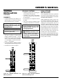
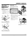
Connect one terminal of 25 ft. wire for
the wall switch to the TPTH terminal
on the valve. Connect remaining wire
terminal to the TH terminal on the
valve. Make sure that the wire terminals are in the positions on the unit as
pictured in Figure 34. If wires are not
connected as shown, the switch will
not work.
Route the 25 ft. wire through openings
provided on the sides of the burner system to a convenient location to mount
your switch.
Connect one bare wire end to each of
the terminals of the GWMS2 wall
switch.
Install the wall switch and cover in the
wall.
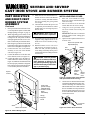
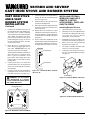
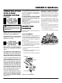
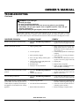
Figure 32 - Checking Gas Joints for Propane/LP Gas Burner System
To Control
Switch or
Optional
Accessory
Equipment
Shutoff
Valve
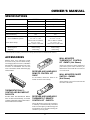
Figure 34 - Control Valve Terminals
Gas Meter
INSTALLING OPTIONAL
WALL MOUNTED
THERMOSTAT - GWMT1
WARNING: Installation must
be done by a qualified installer
familiar with low voltage wiring
procedures.
Gas Valve
WARNING: Do not connect
this thermostat to any electrical
source! Electrical shock and/or
fire hazard will occur.
Figure 33 - Checking Gas Joints for Natural Gas Burner System
1.
2.
Open lower door panel. The valve is
attached to the underside of the burner
system assembly.
Disconnect from the valve the wires
running from the ON/OFF switch.
Continued
106707
15
For more information, visit www.desatech.com