1
MATRIX SWITCHERS
MANUAL PART NUMBER: 400-0047-004
PRODUCT REVISION: 2
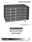
MAX SERIES
MATRIX SWITCHERS
USER’S GUIDE
MATRIX SWITCHERS
INTRODUCTION
TABLE OF CONTENTS
Page
Altinex appreciates your purchase of the MAX
Series Matrix Switcher. We are sure you will find it a
reliable and useful product.
PRECAUTIONS/SAFETY WARNINGS..................2
GENERAL ..........................................................2
Superior performance for the right price backed by
solid technical and customer support is what we
have to offer.
INSTALLATION ..................................................2
RACK-MOUNT INSTALLATION .........................2
The product you are holding in your hands is
designed using state-of-the-art technology and is
superior to anything available on the market. You
will find this and our other products reliable, long
lasting, and simple to operate.
CLEANING .........................................................2
FCC NOTICE......................................................2
ABOUT YOUR MAX SERIES MATRIX
SWITCHER ...........................................................3
We are committed to providing our customers with
solutions to the most demanding audio-visual
installations at very competitive pricing.
TECHNICAL SPECIFICATION ..............................3
We appreciate your selection of our products and
are confident that you will join the ranks of our
many satisfied customers throughout the world.
BACK PANEL CONTROL................................... 5
DIAGRAM OF FRONT/BACK PANEL....................4
H & V SYNC, COMPOSITE SYNC .....................5
AUDIO PORTS (L&R).........................................5
RS-232 PORTS 1&2...........................................5
This manual covers:
APPLICATION DIAGRAM...................................... 6
MXAxxyy – VmAn
MXVxxyy – VmAn
MXRxxyy – VmAn
INSTALLING YOUR SWITCHER...........................9
OPERATION..........................................................9
where
FRONT PANEL CONTROL ................................9
MXA
Audio (Mono / Stereo) switcher
RS–232 PROGRAMMING AND CONTROL ..... 12
MXV
Video (Composite, S-Video &
Component) switcher, with 100 MHz
bandwidth
PROJECTOR CONTROL ................................. 17
MXR
WINDOWS BASED CONTROL
SOFTWARE .....................................................18
Video (High resolution RGsB, RGBS,
RGBHV) switcher, with 400 MHz
bandwidth
xx
number of inputs per each of MAX
switcher module, xx-04/08
yy
number of outputs per each channel
MAX switcher module, yy-02/04
m
number of channels of video signals in
the switcher, m = 1 to 5
n
number of channel of audio signals in
the switcher, n = 1/2
IR-CONTROL MODE........................................ 19
CABLES AND ACCESSORIES............................20
FAQ (FREQUENTLY ASKED QUESTIONS) ....... 20
TROUBLESHOOTING GUIDE.............................21
ALTINEX POLICY................................................22
LIMITED WARRANTY ...................................... 22
RETURN POLICY.............................................22
CONTACT INFORMATION ..............................22
1
MATRIX SWITCHERS
PRECAUTIONS/SAFETY WARNINGS
hazardous conditions may be created by an
uneven weight distribution. Allow 1-U of rack
space for every four MAX Switcher modules for
air circulation. This will reduce heat build up and
will prolong the life of the MAX Switcher.
1
Please read this manual carefully before using your
MAX Series Matrix Switcher. Keep this manual
handy for future reference. These safety
instructions are to ensure the long life of your MAX
Series Switcher and to prevent fire and shock
hazard. Please read them carefully and heed all
warnings.
•
Connect the MAX Series Switcher to a properly
rated power outlet.
•
Reliable Earthling of the MAX Series Switcher
should be maintained by connecting using the
provided 3-prong power cord only. Furthermore,
make sure that the rack is properly grounded.
1.1 GENERAL
•
Unauthorized personnel shall not open the unit
since there are high-voltage components inside.
•
Qualified Altinex service personnel, or their
authorized representatives must perform all
service.
1.4 CLEANING
1.2 INSTALLATION
•
•
•
For best results, place the MAX Series Switcher
on a flat, level surface in a dry area, away from
dust and moisture. To prevent fire or shock, do
not expose this unit to rain or moisture. Do not
place the MAX Switcher in direct sunlight, near
heaters or heat radiating appliances, or near
any liquid. Exposure to direct sunlight, smoke,
or steam can harm internal components.
•
Unplug the MAX Series Switcher’s power cord
before cleaning.
•
Clean surfaces with a dry cloth. Never use
strong detergents or solvents such as, alcohol
or thinner. Do not use a wet cloth or water to
clean the unit.
1.5 FCC NOTICE
Handle your MAX Switcher carefully. Dropping
or jarring can damage the internal components.
Do not place heavy objects on top of the MAX
Switcher.
•
This device complies with part 15 of the FCC
Rules. Operation is subject to the following two
conditions: (1) This device may not cause
harmful interference, and (2) this device must
accept any interference that may cause
undesired operation.
•
This equipment has been tested and found to
comply with the limits for a Class A digital
device, pursuant to Part 15 of the FCC Rules.
These limits are designed to provide reasonable
protection against harmful interference when
the equipment is operated in a commercial
environment. This equipment generates, uses,
and can radiate radio frequency energy and if
not installed and used in accordance with the
instruction manual, may cause harmful
interference to radio communications. Operation
of this equipment in a residential area is likely to
cause harmful interference in which case the
user will be required to correct the interference
at his own expense.
•
Any changes or modifications to the unit not
expressly approved by Altinex, Inc. could void
the user’s authority to operate the equipment.
Do not place the MAX Switcher in direct
sunlight, near heaters or heat radiating
appliances, or near any liquid. Exposure to
direct sunlight, smoke or steam can harm
internal components. Do not pull power cord or
any signal cables that are attached to the MAX.
If the MAX is not to be used for an extended
period of time, disconnect the power cord from
the power outlet.
1.3 RACK-MOUNT INSTALLATION
•
Use only Altinex supplied rack-mount ears for
mounting the MAX Switcher into a rack.
•
The maximum operating ambient temperature is
45 degrees Centigrade.
•
When installing the MAX Series Switcher into a
rack, distribute individual units evenly, otherwise
2
MATRIX SWITCHERS
ABOUT YOUR MAX SERIES MATRIX
SWITCHER
Height (inches)
Width (inches)
Length (inches)
Weight (pounds)
2
The Altinex MAX Series Matrix Switchers are
designed to route multiple computers or video
sources to multiple display devices in a wide range
of audio/visual installations.
Ship Weight
(pounds)
ELECTRICAL
Video Signals
(Inputs & Outputs)
RGBHV
x
—
—
RGBS
x
—
—
RGsB
x
—
—
Component Video
x
x
—
C-Video
x
x
—
S-Video
x
x
—
Audio
x
x
x
Frequency
Compatibility
Bandwidth (MHz)
400MHz 100MHz 100 kHz
Rise Time (ns)
1.2ns
3.1ns
—
Fall Time (ns)
1.2ns
3.1ns
—
Gain Default
1.05
1.05
6dB
Setting
Output impedance
75ohms
75ohms 10ohms
Input Video Level
+/-1 V
+/-1 V
Line
max
max
level
Input Sync Level
TTL or
—
—
Analog
Internal Power
90- 260V
Supply
Power
10-15W 30W max
Consumption
The MAX Series line of matrix switchers is available
in the following sizes: 4x2, 4x4, 8x2, 8x4. The
bandwidth of 100 MHz is available for composite
video, s-video & components switching and 400
MHz for high-resolution video RGB switching.
The versatility of the MAX Series Switcher allows
Altinex to deliver the perfect matrix switcher to fit
your audio visual needs.
The MAX Series Matrix Switcher is designed for
ease of use and flexibility of operation, allowing a
non-technical person to perform intuitively all
switching functions using the front panel control. It
offers extensive and powerful capabilities to the
advanced user through RS-232 control.
Some of the unique features of the MAX Series
Switcher include high bandwidth, Projector control
capabilities, Sync Delay Switching (allows the
“glitch” to take place off the display screen, dual
RS-232 port and easy to use Front Panel control.
With all these exceptional features, the MAX Series
is the perfect solution for your audio/visual
equipment needs.
TECHNICAL SPECIFICATION
FEATURES/
DESCRIPTION
GENERAL
Inputs
BNC (F) (Video)
5-position Terminal
Block (Audio)
Coupling
Outputs
BNC (F) (Video)
5-position Terminal
Block (Audio)
Coupling
MECHANICAL
Material
MXR
3
MXV
MXA
x
x
x
x
x
DC
DC
DC
x
x
x
x
x
DC
DC
DC
5.25in (133mm)
17.00in (432mm)
9.50in (241mm)
11.0lbs
8.0lbs
7.0lbs
(5.0kg)
(3.6kg)
(3.2kg)
16.0lbs
13.0lbs 12.0lbs
(7.3kg)
(5.9kg) (5.4kg)
Adjustments/
Controls
Front Panel
RS-232 ( 2 ports)
Supply through RS232 port1 (+5V)
Supply through RS232 port2 (+12V)
Included
Manual
Rack Mount
Brackets
DA1296RM
0.47’ thick Aluminum
3
x
x
100 mA max
100 mA max
x
x
MATRIX SWITCHERS
Power Cord
5-position Terminal
Connector
4-position Terminal
Connector
x
x
x
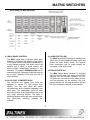
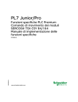
DIAGRAM OF FRONT/BACK PANEL
4
4
MATRIX SWITCHERS
4.3 AUDIO PORTS (L&R)
4.1 BACK PANEL CONTROL
The MAX Series Matrix Switcher is available with
either mono or stereo balanced audio inputs and
outputs for clear quality sound. The terminal
block connectors used for Audio simplify the
connection of the Audio signal.
The MAX Series Matrix Switcher offers great
flexibility in configuring the switcher. Each portion
of the signal can be controlled independently or
in any desired grouping. This allows use of the
switcher with a variety of signal formats, and
allows multiple independent switchers in one
enclosure. For example, MXR0804-V3A0 can be
used as three 8x4 Composite Video Switchers or
as one 8x4 Composite Video with one 8x4 SVideo Switcher.
4.4 RS-232 PORTS 1&2
The MAX Series Matrix Switcher is equipped
with two RS-232 ports. This allows control of the
switcher from two different locations. The RS232 ports can be used to control other devices,
such as projectors, by the switcher. The front
panel switches can be programmed to activate
RS-232 commands to be sent to the projector.
4.2 H & V SYNC, COMPOSITE SYNC
The horizontal and vertical sync ports are
designed to handle TTL and Analog Sync
signals. The two sync ports will switch
simultaneously when controlled separately from
video ports. The independent control of video
and sync portions of the signal allows use of the
sync delay switching function. The delay in
switching between video and sync insures noisefree (glitch-free) switching between any
channels.
5
MATRIX SWITCHERS
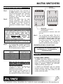
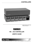
The computer video signal can be RGsB, RGBS, or
RGBHV format. The broadcast video signal can be
C-Video, S-Video, or Component Video in NTSC,
PAL or SECAM standard. The audio signal can be
Mono or Stereo.
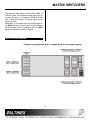
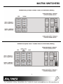
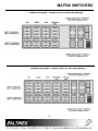
Depending on the signal and size configuration of
the MAX Switcher, the back panel of the switchers
will be different. Here are examples of an 8x4 MAX
switcher for different number of signals.
APPLICATION DIAGRAM
5
6
MATRIX SWITCHERS
7
MATRIX SWITCHERS
8
MATRIX SWITCHERS
INSTALLING YOUR SWITCHER
Step 1.
Step 2.
6
Connect the power entry connector of
the MAX Switcher to the power outlet
with the provided power cord. The power
supply is universal and will work
throughout the world with voltages
between 90V-260V.
Connect the cables from the video
sources (computers, VCR, others) to
available inputs 1 through 8 and connect
the display device (i.e. monitor or
projector) to available outputs 1 through
4.
CAUTION:
All video inputs to MAX Series are DC coupled
for best performance. Even though the video
inputs are fully isolated, verify with an
electrician that all of the grounding is proper
and that GROUND LOOP problems are
minimized.
Severe
Ground
loop
type
conditions can damage equipment.
MAXIMUM VIDEO INPUT: +/-1.2 VOLTS
MAXIMUM AUDIO/SYNC INPUT: +/- 5 VOLTS
Step 3.
Step 4.
If a control system is used to control the
unit, connect the RS-232 port of the
MAX Switcher to the control system’s
RS-232 port as show in Table 1.
If the connection is incorrect, LED’s will
turn red.
Turn on the power switch. The unit is
now operational. You should observe the
power LED on the back panel “ON” and
the VIDEO or AUDIO switch LED light
on the front panel “ON”. You are ready
to either program your switcher or
perform switching from the front panel.
CONGRATULATIONS! YOU ARE DONE.
If you experience any problems, please call
1-800-258-4623 or 1 (714) 990-2300 for
international calls.
RS-232 port of MAX
Computer or
switcher
Control System
Tx ( Transmit)
Receive
Rx (Receive)
Transmit
GND (Ground)
Ground
+12V / +5V
N/C
Table 1. MAX Switcher RS-232 port control
OPERATION
7
7.1 FRONT PANEL CONTROL
The MAX Series Matrix Switcher is designed to
perform a variety of functions using the front
panel control. All front panel switches have three
modes of operation: PRESS and RELEASE,
PRESS and HOLD and Power ON.
Make sure that the transmit pin of the
control system is connected to the
receive pin of the switcher.
Test the units outside of the rack prior to
installation to insure that you have
established communication.
If the connection is correct, both Rx & Tx
LED’s (located below contact pins) on
the selected RS-232 port will turn green.
In PRESS and RELEASE mode the switcher
performs primary functions. Simply press and
release the button right after a beep. An LED
usually verifies the action.
9
MATRIX SWITCHERS
In PRESS and HOLD mode the switcher
performs secondary functions. Press and hold
the button until all LED’s flash and the unit beeps
a second time.
For example, to display the signal from a
source connected to input 3 on the monitors
and connected to outputs 1 and 3 press:
INPUT3 + OUTPUT1 & INPUT3 + OUTPUT3
or OUTPUT1 + INPUT3 & OUTPUT3 +
INPUT3
In POWER-ON mode the switcher changes
settings that are stored in the switcher’s memory.
These modified settings become the default
settings next time the unit is powered.
SAVING SWITCHER CONFIGURATION IN
MEMORY
Once it is defined which outputs are connected
to which inputs, the switcher configuration can
be stored in one of the eight available
memories.
The LED lights located next to any switch on the
front panel of the switcher have four basic states
of operation: OFF, ON, SLOW FLASH, and
FAST FLASH. Each state represents certain
actions that can be taken by the operator.
To store the switcher configuration, press
INPUT 1 through 8, and hold the button until all
LED’s flash and the unit beeps. By doing this a
preset or salvo of input to output connections is
stored into the memory location for a later
recall.
When the LED is OFF or ON the switcher is in a
Normal Mode and no action by the operator is
required.
When the LED’s SLOW FLASH or FAST FLASH
the switcher is in a Set-Up Mode.
The SLOW FLASH indicates that a particular set
up action can be either completed or canceled.
BAUD RATE SETTING
The BAUD RATE setting is important for the
remote control function of the switcher, through
RS-232 ports.
If the lights are in a FAST FLASH state, it is an
indication of what is actually connected and that
an action is required to perform switching.
The factory default setting is 2400 baud, 8 bits,
1 stop, and no parity.
Whenever switching is to be initiated, the
switcher must be in a Normal Mode. The Input
and Output LED’s should be either ON or OFF.
To change to 1200 baud rate, press and hold
the Input1 key and turn the power ON. Then
wait for a long and short beep.
The number of input switches will be according
to your matrix configuration. The remaining
switches will only be usable for the secondary
functions. For example, in a 4x4 switcher all 8
input switches might be present, but only 4 are
active for Input Selection, while all 8 can be used
for secondary functions.
To change to 2400 baud rate, press and hold
the Input2 key and turn the power ON. Then
wait for a long and short beep.
To change to 4800 baud rate, press and hold
the Input3 key and turn the power ON. Then
wait for a long and short beep.
CONNECT INPUT TO OUTPUT
To connect any input to any output press
sequentially [INPUT (n)] +[OUTPUT (m)]. This
function can also be performed by pressing
[OUTPUT (m)]+[INPUT (n)]. When you press
INPUT(n) the LED next to that input switcher
will SLOW FLASH indicating that the operation
is not completed and a particular action is
required. Pressing the desired OUTPUT(m)
switch will complete the operation. When the
connection is made both the INPUT and
OUTPUT LED’s will be ON.
To change to 9600 baud rate, press and hold
the Input4 key and turn the power ON. Then
wait for a long and short beep.
SET UNIT SYNC DELAY FUNCTION
Sync delay allows the MAX Switcher to delay
the switching by a specified time after the
commands are issued to switcher. The power
up at factory reset default function is for NO
SYNC DELAY.
10
MATRIX SWITCHERS
Press and hold Input 5 and turn the power ON.
Then wait for long and short beep to set the No
sync delay function.
Press and hold Output 4 and turn power ON,
then wait for long and short beep to set the unit
ID to 4.
Press and hold Input 6 and turn the power ON.
Then wait for long and short beep to set a 5second sync delay.
RECALL PRE-SET MEMORY
If any connection configuration of inputs to
outputs is stored into the switcher’s memory, it
can be recalled using this option. To switch to
RECALL mode, press and hold the RECALL
key in switcher/projector control section on the
bottom right corner of the front panel. The unit
beeps once and all input switch LEDs will flash.
Select the memory location to recall from 1
through 8. After the selection, all stored input
to output connections will be restored.
Press and hold Input 7 and turn the power ON.
Then wait for long and short beep to set a 2second sync delay.
Other sync delay values can be programmed
into the switcher using RS-232 control
commands.
IR CONTROL
The MAX Switcher can be equipped with an
optional RC5251IR, Infra-Red Remote Control.
To have the MAX Switcher recognize the InfraRed Remote Control Receiver attached to RS232 port1, please press and hold the IRControl key (INPUT section key#8) while
turning the power ON. The switcher will beep a
couple of times and an ON LED next to IRControl key will verify that the MAX Switcher is
ready to be controlled by RC5251IR. To
disable the IR-mode, the switcher has to be
reset.
SELECT SIGNAL
AUDIO & VIDEO keys allow break away
switching of the audio and video signals
through the front panel.
By selecting AUDIO and deselecting VIDEO,
only the audio portion of the input and output
channels
will
change
by
subsequent
input/output connections. If the AUDIO switch
is de-selected and only the VIDEO switch is
selected, the audio portion of the signal will not
change with subsequent connections.
Normally, both the AUDIO and VIDEO switches
are selected and both LED’s are ON to provide
Audio-follow-Video switching.
SET UNIT ID NUMBER
When the same control equipment or PC
controls more than one MAX Switcher, then it
is convenient to address each MAX Switcher
separately by RS-232 commands, by assigning
different unit ID numbers.
STATUS
When the STATUS key is pressed and held,
the Front Panel will show system settings of
the MAX Switcher such as Baud rate, Unit ID,
SYNC Delay time, and IR-Control Status.
Press and hold Output 1 and turn the power
ON. Then wait for a long and short beep to set
the unit ID to 1. If the unit ID is 1 then MAX
Switcher responds to all commands that are
sent.
SOUND
This switch is used to enable/disable audible
response (beep), whenever any key is pressed
on the Front Panel. The default is SOUND on.
To disable Sound (Beep), press and hold the
SOUND key for approximately 2 seconds until
all LED’s flash. The sound function is now
disabled. This is a toggle function, so to enable
the sound, repeat the same step.
To set the unit ID to 2, press and hold the
OUTPUT2 key while turning the power ON.
Wait for a long and short beep, to allow the unit
ID to change to 2.
Press and hold Output 3 and turn power ON.
Then wait for long and short beep to set the
unit ID to 3.
11
MATRIX SWITCHERS
command is not recognized an [ERR] string will
be returned.
RESET
To reset the switcher to its factory default
setting, press [VIDEO] and hold it until all
LED’s flash.
1. SQUARE BRACKETS ARE PART OF THE
COMMAND.
2. USE UPPERCASE LETTERS FOR ALL
COMMANDS.
3. PLEASE PUT A 50 ms DELAY BETWEEN
TWO CONSECUTIVE COMMANDS.
When the switcher is reset:
-
Baud rate is changed to 2400 bps.
-
Unit ID is selected to 1.
-
IR-Control mode is disabled.
-
Sync Delay is set to None.
-
All stored memories are cleared.
The RS-232 commands are divided into two
groups: Programming & Control.
LOCK / UNLOCK FRONT PANEL
Sometimes it is advantageous to disable the
front panel control to ensure that it is not being
operated while the remote control is being
performed or to avoid accidental changes in
system settings/configuration of the switcher by
a curious user. Press the [STATUS] key and
HOLD until the LED flashes. The front panel is
now disabled. To enable front panel, press
[STATUS] key and HOLD it until the LED’s
flash. Now the front panel is enabled.
7.2.2 PROGRAMMING COMMANDS
NOTE: These programming commands are
used for setting defaults and
configuring the switcher. It should not
be used as a part of a program to
operate
the
switcher.
The
programming setting changes done
through these commands are stored in
non-volatile memory. Typically these
commands can be issued 10,000
times before the memory needs to be
replaced.
7.2 RS–232 PROGRAMMING AND CONTROL
The MAX Series has many advanced remote
control capabilities, which are accessible through
standard RS-232 ports through terminal block
connectors provided on the back panel. The
MAX Switcher can be controlled through a
computer or control system.
[SETIDn]
n= Unit ID number 0-9, A-Z, a-z
This command sets a unique ID number to
each MAX Switcher and allows control of
multiple modules through a single RS-232 port.
Setting unit ID allows a user to send a
command to multiple modules, but the
command is processing by module with the
indicated ID number only.
7.2.1 RS-232 PROTOCOL
The Standard RS-232 protocol for the MAX
Series Matrix Switcher uses simple ASCII
character format.
The unit ID can be any number or any other
ASCII alphanumeric character. A total of 62
unit ID numbers are available. If the unit ID is
set to 1 then all switchers will always
communicate. From the factory all new units
are shipped with unit ID number 1. When the
MAX is powered "ON" the default unit ID
number is 1 regardless of the actual unit ID
setting. If the ID level is set to 0, then the unit
will not respond to any command other than
[SETIDn].
The RS-232 input has a 16-character buffer
and will not execute any additional commands
until the previous command is fully processed.
After processing a valid command an [OK]
string will be returned followed by command
echo. For example, the [RSET] command will
return [OK][RSET]. Version number command,
[VERN] will return the firmware version of the
switcher, without [OK] such as [1.0]. If a
12
MATRIX SWITCHERS
work. Once programmed this setting remains
in effect even after power is turned on or off.
This command is used for programming the
switcher. It should not be used as a part of a
program to operate the switcher.
The [SETIDn] command is used for
programming the switcher; it should not be
used as a part of a program to operate the
switcher.
[CODEn]
n=1 - Use [ ] as start and end code
[InnOmmA]
nn - Input Number 00 to 96
n=2 - Use ( ) as start and end code
mm- Output Number 00 to 96
n=3 - Use {} as start and end code
This command defines the offset for inputs and
outputs of a MAX Switcher. This command is
used when the number of inputs or outputs on
the switcher needs to be expanded. This
command allows continuous numbering of
inputs and outputs as the number of inputs and
outputs is increased. For example, if a 12 by 8
matrix switcher is made using two MAX 8x4
switchers, this command will allow you to
arrange inputs end outputs so a command like
[I12O04] is recognized. In this case the first
switcher will have the offset of inputs and
outputs set to zero by the [I00O00A] command
and the second switcher will have input offset 8
through the [I08O00A] command.
n=4 - Use :; as start and end code
n=5 - Use <> as start and end code
n=6 - Use : \ as start and end code
Default n=1
Through this command start and end code
(command delimiters) for RS-232 control,
command strings can be defined. This
command can be used for controlling the
switcher using different start and end codes.
This is an extremely powerful command and
can be used to control multiple switchers
individually from a single RS-232 control card
or PC.
For example, one switcher can be set to have
square brackets “[ ]” as the start and end code
though the [CODE1] command. The other
switcher is set to have round brackets “( )” as
start and end though the [CODE2] command.
To control the first switcher the command
would be [I02O03], but the same command to
control a second switcher would be (I02O03).
With this offset command, a matrix switcher
can build with a size up to 96x96. This
command is used for programming the
switcher. It should not be used as a part of a
program to operate the switcher.
[IkkOnnL]
nn – loop offset number 00 to 08
kk – any number from 00 to 99
If codes are used to identify and control
individual units, then some general commands
which do not include unit ID no. in them can be
easily issued. For example, each unit can be
reset
individually
using
the
following
commands: [RSET] and (RSET).
This command is used when looping several
switchers together to increase the number of
inputs. The input offset will be the same as the
number of the last input of the previous unit
and it is sent to the switcher through the
[IkkOnnL] command. After programming
looped units, they can be controlled by a single
command, [IxxOyy] where xx is any number
from 01 to 99. Without this loop command
capability, units can be controlled with the
[IxxOyy] command but if several commands
are sent there will be a delay between two
consecutive commands. To avoid problems,
make sure that the following steps are taken:
[InnOmmS]
nn - Input Number 01 to 08
mm- Output Number 01 to 04
Set the maximum number of inputs and
outputs used on the MAX Switcher. This
command is used at the factory at the time of
set up. If the maximum number of inputs is set
to 4, then input buttons 5,6,7, and 8 will not
13
MATRIX SWITCHERS
1. The number of outputs must be the same
on all units to be looped.
2. Output offset is zero for all units.
3. The input offset must be set for all units
except for the first one. The offset for the
input should be the same as the last
number of the previous unit
4. The number of inputs available on the
second unit for a direct connection is the
difference between the maximum number
of inputs of the second unit, and the
number of looped outputs.
[SDELnn]
nn - value from 00 to 99, Sync delay
time in multiple of 65 ms.
5. Set the loop offset separately for each unit.
The loop offset is zero for the first unit. For
other units the loop offset is the number of
outputs of the previous unit.
This command sets Sync delay time in 65ms
increments. The sync delay can be set to a
minimum of none or to a maximum of 6.4
seconds. The sync delay function is useful to
avoid an unwanted image (a glitch) that
appears on the projector or monitor screen
when switching between different sources of
different signal resolutions. Typically, a 0.5
seconds delay will clean up the image on most
of the displays during the switching. Keep in
mind that making the sync delay too long will
require the user to wait before implementing
the next command until the prior command is
executed. When specifying sync delay, capital
letters A through F also can be used to get a
longer delay. For example, [SDELFF] will
provide almost 19 seconds of delay.
Example: If the user wants to create a 12x4
switcher, use two 8x4 matrix switchers.
Connect output 1 through 4 of the first unit to
the last four inputs of a second unit in
increasing order. Please program each MAX
Switcher individually using the following table:
PARAMETER
UNIT A
UNIT B
Size
[I08O04S]
[I08O04S]
Offset
[I00O00A]
[I08O00A]
Loop
Command
[I00O00L]
[I00O04L]
Now if you send the commands as follows, the
active connectors will be as follows on both
units:
n=00 corresponds to no Sync delay
n=08 corresponds to 0.5 second delay
COMMAND
UNIT A
Connection
UNIT B
Connection
[I02O02]
2-2
14 - 2
[I09O04]
9-4
16 - 4
[16O04]
16 - 4
16 - 4
[17O01]
NONE –1
1-1
[128O04]
NONE – 4
12 - 4
[129O03]
NONE - 3
NONE - 3
n=38 corresponds to 2.5 second delay.
n=99 will set Sync delay of 6.4 second
[VERN] - Version
This command will return the current version of
the firmware used on the switcher. It does not
require the feedback command to return the
feedback. For example if [VERN] is typed, the
feedback of [3.2] will return from the MAX
switcher.
14
MATRIX SWITCHERS
command actions are lost if power to the unit is
lost or if the unit is reset in any way.
[RSET]
This command resets or initializes the switcher
to the power-on condition. With this command,
the baud rate is changed to 2400 bps, all
current inputs from outputs are disconnected,
unit ID number is set to 1, memory number 1 is
recalled, and all levels (VIDEO & AUDIO) are
enabled.
[UIDn]
n = unit ID number 0-9, A-Z, a-z
This command is used to enable all switchers,
disable all switchers or enable individual
switchers with specific unit ID numbers.
n=0
All units with IDs 0-9, A-Z, a-z are
disabled and only respond to
another [UIDn] command. This
allows pass-through control of other
RS-232 devices on the same RS-232
line without effecting the MAX.
[BAUDn]
n=1(31hex)
300 baud
n=2(32hex)
600 baud
n=3(33hex)
1200 baud
n=4(34hex)
2400 baud
n=5(35hex)
4800 baud
n=6(36hex)
9600 baud
n=1
This command switches the MAX Switcher into
different baud rates. The factory default baud
rate setting is for 2400 bps.
All units with IDs 0-9, A-Z, and a-z
are enabled and respond to any of
the RS-232 commands. This allows
simultaneous control of all MAX’s
connected to the same RS-232 port.
n=2 through 9, A through Z, a through z
Enables an individual MAX Switcher.
This command does not disable any
units.
The same code for baud rate is used to control
projectors from the MAX Series Switcher.
When controlling other devices, the MAX
Series has the ability to output RS-232
commands at a specified baud rate yet still be
controlled by a fixed baud rate control system.
For example, if [UID3] is issued followed by
[UID2] then both units 3 and 2 will respond to
the issued commands. To disable all switchers
and enable any particular switcher, issue
[UID0] followed by [UIDn] of the switcher that
needs to be enabled.
For example, if you need to control projector
using 2400 baud and your control system
operates at 9600 baud, you can program the
MAX Switcher to output commands at 2400
baud rate and receive them at 9600 baud.
[SELn]
n=0 Control all channels together
[VIDEO+AUDIO]
[BEEPn]
n=1 Beeper ON
n=1 Control Red
n=2 Control Green
n=0 Beeper OFF
n=3 Control Blue
This command allows the beep sound to be
turned ON or OFF on the MAX Series
Switcher, which is generated while pressing a
key on the front panel or processing a valid
RS-232 command.
n=4 Control H–Sync and V-Sync
n=5 Control Audio Right
n=6 Control Audio Left
n=7 Control Audio Right and Left (Audio
channels)
7.2.3 CONTROL COMMANDS.
These control commands are used for
controlling the switcher: they are a part of a
program to operate the switcher. These
n=8 Control Red, Green, and Blue
n=9 Control Red, Green, Blue, and H
and V Sync (Video channels)
15
MATRIX SWITCHERS
This command allows control of each signal
level independently. Once issued it is active
until another [SELn] command is issued or the
front panel is used to control the switcher.
mm- output number 01 to 04
P - path
This command sets the switching path of
connecting an input to an output but does not
switch.
When the front panel is used, the levels to be
controlled are defined by the front panel
selections. The front panel allows only 3
options of controlling channels; either AUDIO
or VIDEO or AUDIO+VIDEO. It is not
recommended to use the RS-232 control and
the front panel at the same time to control
different channels since front panel will
override RS-232 controls.
Through this command input to output
connections are loaded (path is set), but not
switched until [SW] or [SWUx] commands or a
direct connection command of [IxxOmm] is
sent.
For example, if you want to connect input 2 to
output 1 and not switch it, the command to be
issued will be: [I02O01P]
The LEDs on the back of the unit display the
status of a particular level. The RED LED
indicates that this level is not enabled for
controlling. The GREEN LED indicates that this
level is currently enabled for controlling.
A typical sequence would look like this:
[I01O02P][I04O01P][I08O03P][I05O04P][SW]
or [I01O02P][I04O01P][I08O03P][I05O04].
[InnOmmUx]
xx Input number 01 to 08
During the power ON the MAX automatically
defaults to n=0 (Control all channels).
[SELnUx]
n = Same as above
yy
Output number 01 to 04
n
Unit ID number 0-9, A-Z, a-z
This command allows any input to be
connected immediately to any output on a MAX
Switcher with a specific unit ID.
This command works the same as above
except for specific unit ID number. This
command allows selection of levels (channels)
on switchers that have been assigned unique
unit ID numbers.
For example, if two MAX Switchers are
connected to the same RS-232 port but have
unit IDs set as 3 and 4, the following command
can be issued to independently control each
unit:
[I02O04U3][[I04O01U4].
The
first
command connects input 2 to output 4 on the
switcher with ID=3 and the second command
connects input 4 to output 1 on the switcher
with ID=4.
[InnOmm]
nn - input number 01 to 08 ( if input
number 00 is used, that input is
disconnected from the selected
output)
mm- output number 01 to 04
[InnOmmUxP]
xx Input number 01 to 08
This command connects Input to Output and
switches them immediately.
For example, if you want to connect input 2 to
output 1 and switch, the command to be issued
will be: [I02O01]. Command [I00O01] will
disconnect output 1 from any input.
yy
Output number 01 to 04
n
Unit ID number 0-9, A-Z, a-z
This command is the same as [InnOmmUx],
however the switching does not occur until
[SWUx] or [SW] or direct connection command
is issued. Through this path command, input to
output connections are loaded, but not
switched.
[InnOmmP]
nn - input number 01 to 08 ( if input
number 00 is used that input is
disconnected from the selected
output)
16
MATRIX SWITCHERS
This command is used to select multiple inputs
and multiple outputs without switching and then
switch them together with a single command.
This is a very useful command for scene or
salvo switching or for controlling through a PC.
inputs and outputs of the specific MAX
Switcher without sending four different
commands with 50 ms delays between each
command. For example, if input 3 needs to be
connected to outputs 1,2,3,4 of the unit with
ID=4, then the following command can be used
[DO03030303U4]. If inputs 4,5,6,7 need to be
connected to outputs 1,2,3,4 on the MAX
switcher with unit ID number 8, then the
following
command
is
issued
[DO04050607U8].
If n = 1, units will respond to any command. If
n= 0, then none of the units will respond to any
issued command, except [UIDn].
A typical sequence would look like this:
[I01O02U2P][I04O01U2P][I08O03U3P][I05O04
U4P]. Set the path for three different switchers
with these commands and then switch them all
together with the [SW] command.
The
switching
of
all
inputs
occurs
simultaneously for all outputs. If sync delay is
in effect, then it will be used before switching.
The unit ID needs to be set for the switcher
that needs to be controlled before using this
command. Input 00 is used to disconnect
output 1 through 4. For example, if you want to
disconnect all outputs on the MAX Switcher
with unit ID number 2, then use the following
command [DO00000000U2].
[DOxxyyzzkk]
xx - Input connected to output 1
yy - Input connected to output 2
zz - Input connected to output 3
kk - Input connected to output 4
Connect any 4 inputs to any 4 outputs of the
MAX Switcher with a single command. This
command allows a quick way of connecting
inputs and outputs without sending 4
commands with a 50 ms delay between each
command. For example, if input 3 needs to be
connected to outputs 1,2,3,4, then the following
command can be used [DO03030303]. If input
4,5,6,7 need to be connected to outputs
1,2,3,4, then the following command is issued
[DO04050607]. The switching of all inputs
occurs simultaneously for all outputs. If sync
delay is in effect, then it will be used before
switching. Input 00 is used to turn a channel
'OFF'. For example, if you want to disconnect
all
channels
use
following
command
[DO00000000]
[SW]
Immediately switch the inputs to outputs, which
are previously set through path commands.
First set the path using [InnOmmP] or
[InnOmmUxP]. Then issue a single [SW]
command
to
switch
all
connections
simultaneously, which are loaded by path
commands. If Sync delay is enabled the [SW]
command will delay switching for that period.
This command is available only when switchers
to be controlled are enabled using [UID1]. This
command is a very useful for scene or salvo
switching or for controlling through a PC.
[SWUx]
x - Unit ID number 0-9, A-Z, and a-z
[DoxxyyzzkkUn]
xx - Input connected to output 1
This command immediately switches inputs to
outputs on a specific switcher with a specified
unit ID number, which is previously set through
a path command.
yy - Input connected to output 2
zz - Input connected to output 3
kk - Input connected to output 4
First the path is set through a [InnOmmUxP]
command and then a single [SWUx] command
is issued to switch all connections
simultaneously. If Sync delay is enabled, the
n - unit ID number 0-9, A-Z, a-z
Connect any 4 inputs to any 4 outputs on a
MAX Switcher with a specific unit ID number.
This command allows quick connection of
17
MATRIX SWITCHERS
connection between inputs and outputs for
active channels of a switcher with a selected
unit ID number.
[SWUx] command will delay switching for that
period.
[FDBKn]
n- 1 enable feedback [OK] or [ERR]
Memory saved in location no.1 is recalled,
when the MAX Switcher is powered up or
RESET. If [Sel7] saves the memory location for
the audio channel, then the switcher will only
recall input to output connection for those
audio channels only. If the unit is switched
using breakaway audio (video channels only by
[SEL9] command), then the input to output
connection of video channels will be loaded.
n- 0 disable feedback
This command sets MAX Switchers to provide
feedback code during RS-232 control
operations. Factory default is no feedback.
After [FDBK1] is issued the MAX Series
Switcher will provide an [OK] if the command is
executed properly and [ERR] if the wrong
command is issued. If [FDBK0] is issued the
MAX Switcher will not provide any feedback to
the control system or program.
7.4 PROJECTOR CONTROL
A projector can be controlled through both RS232 ports or through activity happening on the
front panel. Please note that one port is enabled
at a time, so if the MAX Switcher is used to
control the projector, it cannot be connected to
and controlled by another RS-232 control source,
such as a PC or Control System.
Since the MAX Series Switcher can control
projectors it is recommended that the feedback
be set to none. This will guarantee that
feedback does not interfere with proper control
of projectors.
To enable port1 of 1 for projector control, press
the Input1 key and then press the Output1 key
once to enable RS-232 port 1. An ON green LED
next to RS-232 port 1 on the back panel confirms
this.
[SAVn]
n- memory location number 0 to 8
The MAX Switcher has 8 memory locations to
store a set of connections. Each memory
location stores one preset (scene or salvo),
which is the current connection between inputs
and outputs for active channels of a switcher
with a selected unit ID number.
To enable port1 of 2 for projector control, press
Input2 key and then press Output2 key once to
enable RS-232 port 2. This is conformed by an
ON green LED next to RS-232 port 2 on the
back panel.
Memory saved in location no.1 is recalled,
when the MAX Switcher is powered up or
RESET. If only [Sel7] saves the memory
location for the Audio channel, the then
switcher will only recall input to output
connections for those audio channels only. If
the unit is switched using breakaway audio
(video channels only by [SEL9] command),
then input to output connections of video
channels will be loaded.
Please note that the receive lines on both ports 1
& 2 are always active regardless of the transmit
line. This means that the MAX Switcher can
receive signals from either port, but it can
transmit signals only on one port at a time. Each
RS-232 port on the MAX Switcher can output
commands at a different programmed baud rate.
The output string will be produced, when any
input is selected and followed by output. Please
contact Altinex for programming instructions to
control a projector.
[RCLn]
n- memory location number 0 to 8
7.5 WINDOWS BASED CONTROL SOFTWARE
This command will allow the MAX Switcher to
recall any of 8 available memories.
This Windows 95/98/NT based Control Software
is available from the Altinex website at
www.altinex.com in the Download section.
Each memory location stores one preset
(scene or salvo), which is the current
18
MATRIX SWITCHERS
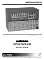
7.6 IR-CONTROL MODE
5.
Wired Infra-red Receiver
Step 1. Make sure that the MAX Switcher is in the
OFF position.
Step 2. Plug the 4-position terminal plug located at
the end of the cable into RS-232 Port 1
located on the top-right corner on the
backside of the switcher.
Note: Inserting the 4-positon Terminal
connector on RS-232 port 2 will damage
the receiver.
Step 3. Please put the receiver within a range of
the transmitter and within 30° angle for
optimum operation.
MAX Switcher
To enable the IR mode on the MAX Switcher,
press and hold the IR Control key (INPUT 8)
on the Front Panel while turning on the power
of the unit. The IR mode is now active. The IR
mode remains enabled on the MAX Switcher
until the unit is reset.
Please note:
1.
When IR mode is enabled on the MAX
Switcher, neither of the two RS-232 ports
is available for manual control of the
switcher.
2.
When IR-Control is enabled for the first
time, the first command sent through the
key will not work since it is used to initialize
the system. However, the MAX Switcher
will execute all subsequent commands.
3.
At certain times, when using commands
INPUT 2>OUTPUT 2, the switcher may
switch the RS-232 function to port 2
disabling IR control. Pressing INPUT
1>OUTPUT 1 will not enable port 1 for IR
control again.
4.
To cancel the IR control mode on the MAX
Switcher, please reset the unit by pressing
the RESET key for two seconds. The
RESET
key
is
located
in
the
Projector/Switcher Control section of the
front panel.
19
Please note that once the IR-mode is
canceled, both remote controls through the
RS-232 ports are available in addition to
the manual control through the front panel.
To enable the IR-mode again, follow the
procedure mentioned above.
MATRIX SWITCHERS
CABLES AND ACCESSORIES
Model No.
8
controlled from
the front panel.
Description
RACK MOUNTING BRACKETS
DA1296RM 19”-3U Rack Mount Ears
TABLE MOUNT BRACKETS
3U High, 1 Rack - Wide
TM1277
CONTROL OPTIONS
RC5251IR Infra-Red Hand-held Remote Control
Transmitter and Receiver with 6 ft
cable
4 BNC TO 4 BNC COAXIAL CABLE
CB4100MR Bulk high resolution 4 coax cable
(500 ft minimum)
CB4300MR Bulk super high resolution 4 coax
cable (500 ft minimum)
5 BNC TO 5 BNC COAXIAL CABLE
CB4200MR Bulk high resolution 5 coax cable
(500 ft minimum)
CB4400MR Bulk super high resolution 5 coax
cable (500 ft minimum)
CB5000PL Bulk high resolution 5 coax cable
(500ft minimum) PLENUM-FLEX
All cables listed above are a pre-cut series available
in lengths of 6 ft, 12 ft, 25 ft, 50 ft, 75 ft, 100 ft and
150 ft with molded BNC connectors. Please call 1714-990-2300 for more information.
FAQ (Frequently Asked Questions)
Question
Answer
1
How do I know
which input is
connected to
which output?
If you press a desired input
button, the fast flashing
LED on OUTPUT will
indicate the present
connections of this input to
all connected outputs.
When you experience lack
of communication, please
check the following:
1. The baud rate setting.
2. Cable connection.
3. Unit ID setting.
3
The MAX
Switcher does
not
communicate
with a PC or
Control
System.
The MAX
Switcher can
not be
Does the MAX
Series come
with rack
mounts?
5
How does one
increase the
number of
inputs or
outputs on the
switcher?
6
May I switch
audio separate
from the
video?
7
May I control
multiple
switchers with
one RS-232
card?
9
No
2
4
Make sure that the front
panel is not disabled. Press
and hold the STATUS key
20
to activate Control through
the front panel. If still it
doesn’t work then reset the
switcher to factory defaults
by pressing and holding the
“VIDEO” button.
Yes, two rack mount ears
should be included with the
unit. If you did not receive
them, please call us and
they will be sent to you.
To increase the number of
inputs, one can add a
second switcher and loop
outputs of the first switcher
to the inputs of the second
switcher. For example, to
create a 12x4 MAX
Switcher, route 4 outputs of
first 8x4 switcher to the
input of a second 8x4
switcher. So 8 inputs go
into switcher 1 and inputs 912 go into switcher 2, while
outputs 1-4 are taken from
the second switcher. To
increase the number of
outputs, use a second
switcher and an interface
with dual outputs. For
example, to create an 8x8
MAX Switcher, use two 8x4
MAX Switchers where
inputs to both switchers
come from an output
distribution amplifier.
Yes, the MAX Series has
full breakaway capability of
Red, Green, Blue, Sync,
and Audio through RS-232
control.
Yes, the MAX Series is
designed to allow the
assignment of different ID
numbers to individual units.
This feature makes it
possible to control multiple
switchers through the same
MATRIX SWITCHERS
8
9
10
Can I use
contact closure
to control the
switcher?
Is the MAX
Series capable
of controlling
various
projectors?
How can I
prevent an end
user from
tinkering with
the controls?
commands being sent. Also make sure that all
commands have a square bracket ‘[‘ before and “]”
after each command if the code is set to 1.
port simultaneously.
Contact closure cannot
control the MAX Switcher
directly, but this can be
done using the Altinex
CP7317RS unit, which is
capable of converting
contact closure control into
RS-232 commands. The
number of relays available
limits the number of
functions available.
Yes, windows based control
software is available to
allow easy control of the
MAX Series Switcher and
other devices connected to
the switcher. Please get it
from the Altinex website at
www.altinex.com in the
Download Section.
Press and hold the
STATUS/FRONT OFF key
until it beeps and all LED’s
on Front Panel are disabled
except this key.
TROUBLESHOOTING GUIDE
Please verify that a correct ID number is assigned
to each unit. If a particular group of modules need
to be controlled then the unit ID number must be
the same for all the modules in that group. The unit
ID number 0 will make the MAX unit not respond to
any command, while unit ID number 1 in the
command will have all units follow the command.
When any Input or Output LED is flashing, please
do not use the SAVE, RECALL, or RESET function.
To use the SAVE function, first connect the desired
INPUTS to OUTPUTS and then press any memory
button from 1 through 8 and keep it pressed until all
lights blink and confirmation is given through an
audible beep.
To use the RECALL function, make sure no INPUT
or OUTPUT LED is flashing and then press the
RECALL button until all lights on memory 1 through
8 blink. Then press the desired memory location to
recall from 1 through 8.
To verify the connection, press any OUTPUT LED,
which will show all inputs, attached to that particular
OUTPUT by flashing INPUT LED’s. To verify the
connection of any particular output, please press
the desired output. All attached inputs to that output
will have an LED flashing.
10
First, make sure that power is connected to the
power-input connector and input power is within the
range of 90-260 VAC.
If you are using RS-232 control for this unit, please
follow the connection instructions as described in
the manual and verify the operation with
downloaded software for PC’s from the
DOWNLOAD section of the Altinex website:
www.altinex.com.
Make sure that cables are connected properly and
fit snugly. Please immediately replace any defective
or damaged cables.
If RS-232 connection is used to control the MAX
Series Switcher, then please make sure that the
connections to each pin of the RS-232 port located
on the back of the unit is as described in step 3 of
section 6.
In the video module, please make sure that the
input level of the video signal RGB is 1.2 V p-p. In
the audio module, the input level of the audio signal
is 5 V p-p.
If a control system is used to control the switcher
through an RS-232 port, make sure that there is at
least a 50 ms delay between two adjacent
21
MATRIX SWITCHERS
ALTINEX POLICY
If your product is out of warranty and needs
service, contact the Altinex Sales Department for
an RMA (Return Material Authorization).
Products returned without an RMA number may
experience a delay in service. The service
charges will be quoted to you before the actual
repairs are done.
11
11.1 LIMITED WARRANTY
Altinex warrants that its MAX Series Matrix
Switchers are free from defects in materials
under normal use and service. This warranty is
limited to repairing at company’s factory any part
or parts of the product, which upon company’s
examination shall disclose to be, thus defective.
Products considered defective should be
returned to company with transportation charges
pre-paid within 2 years (90 days for cables) from
date of shipment to the purchaser. The warranty
is expressly instead of all other warranties
expressed or implied. Altinex neither assumes
nor authorizes any other person to assume for it
any other liability concerning the sale of the
products. This warranty shall not apply to any
product that shall have been repaired or altered
outside of company’s factory in any way so as, in
its judgment, to affect its stability or reliability, or
that has been subject to misuse, negligence or
accident.
11.3 CONTACT INFORMATION
Sales Department
Phone:
Fax:
714-990-2300
714-990-3303
Accounting Department
Phone:
714-990-6088
Fax:
714-990-5778
11.2 RETURN POLICY
It is very important to Altinex that you receive the
products that you have ordered and that this
product fulfills your need. In the unlikely event,
that an Altinex product needs to be returned
please follow the policies below:
Altinex will accept product returns for a period of
30 days from authorized Altinex dealers.
Products must be returned in an unopened
package.
If a product has been opened, the restocking
fees will apply. For the restocking fee amount,
please contact an Altinex Sales Representative.
If the product is in your possession for more than
30 days, the restocking fees will apply.
Altinex will not accept any returns on cables or
custom products.
If your product is in warranty and needs service,
contact the Altinex Sales Department for an RMA
(Return
Material
Authorization).
Products
returned without an RMA number may
experience a delay in service.
22