1
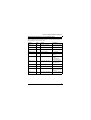
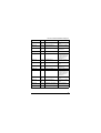
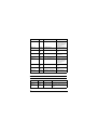
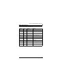
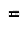
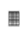
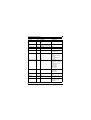
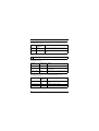
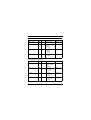
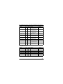
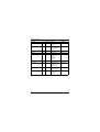
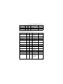
Modicon Premium PLCs
TSX CSY 84 / 85 / 164
SERCOS
®
Motion Control
Reminder
Edition June 2009
TSX CSY 84/85/164 Module
TSX CSY 84/85/164 module using PL7
Implicitly Exchanged Input Variables
5
Implicitly Exchanged Output Variables
7
Adjustment Parameters for the SERCOS® Function
11
Adjustment Parameters for an Individual Axis
11
Adjustment Parameters for a Set of Follower Axes
13
Constant Words
16
WRITE_CMD Parameters
17
TRF_RECIPE Parameters
18
Motion Control Functions
18
Move Functions
19
Adjustment Functions
20
Diagnostic Functions
23
Configuration functions
24
Read/Write Functions for IDN Parameters
25
1
List of TRF_RECIPE command codes
26
Module Faults Accessible via Word %MWxy.MOD.2
27
Channel Faults Accessible via Word %MWxy.i.2
27
Faults Accessible via Word %MWxy.i.3 (TSX CSY 85)
28
Programming Faults Accessible via Word %IWxy.i.2
30
WRITE_CMD Command Writing Faults
33
Faults Accessible via the GetMotionFault Command
36
Faults Accessible via the GetMotionWarning Command
37
User Notes
39
2
TSX CSY 84/85/164 Module
TSX CSY 84 module using Unity Pro
T_CSY_CMD type ODDT implicit exchange objects
41
T_CSY_CMD type ODDT explicit exchange objects
43
T_CSY_RING type ODDT implicit exchange objects
44
T_CSY_RING type ODDT explicit exchange objects
47
T_CSY_TRF type ODDT explicit exchange objects
50
T_CSY_IND type ODDT implicit exchange objects
51
T_CSY_IND type ODDT explicit exchange objects
56
T_CSY_FOLLOW type ODDT implicit exchange objects
61
T_CSY_FOLLOW type ODDT explicit exchange objects
65
T_CSY_COORD type ODDT implicit exchange objects
80
T_CSY_COORD type ODDT explicit exchange objects
84
T_CSY_CAM type ODDT implicit exchange objects
87
T_CSY_CAM type ODDT explicit exchange objects
88
IODDT T_GEN_MOD applicable for all modules
91
User notes
92
3
4
TSX CSY 84/85/164 Module using PL7
Implicitly Exchanged Input Variables
The following 32 input bits and the input word are implicitly exchanged between the
processor and the axis control module:
Address
Type
Symbol
%Ixy.i.ERR
Bit
ERR
Description
Channel fault
%Ixy.i.0
Bit
RAMPING
Indicates whether the axis is
accelerating or decelerating
%Ixy.i.1
Bit
STEADY
The speed is steady
%Ixy.i.2
Bit
STOPPING
The movement is
decelerating to a stop
%Ixy.i.3
Bit
PROFILE_END
The last profile command has
been sent to the module
%Ixy.i.4
Bit
IN_POSITION
The axis is within the inposition band
%Ixy.i.5
Bit
AXIS_HOMING
The axis is homing. For an
imaginary axis, this bit is
inactive
%Ixy.i.6
Bit
AXIS_HOMED
The axis position reading is
referenced off the home
position
%Ixy.i.7
Bit
AXIS_NOT_FOLLOWING
The drive is not recognizing
module commands
%Ixy.i.8
Bit
HOLDING
The axis is holding
%Ixy.i.9
Bit
RESUMING
The axis is moving after a
hold
%Ixy.i.10
Bit
DRIVE_ENABLED
The drive is enabled
%Ixy.i.11
Bit
DRIVE_DIAG
The drive is performing a
class 3 diagnostic
%Ixy.i.12
Bit
DRIVE_WARNING
The drive is performing a
class 2 diagnostic
%Ixy.i.13
Bit
DRIVE_FAULT
The drive is performing a
class 1 diagnostic
%Ixy.i.14
Bit
DRIVE_DISABLED
The drive is disabled
5
Address
Type
Symbol
Description
%Ixy.i.15
Bit
AXIS_SUMMARY_
FAULT
Drive fault
%Ixy.i.16
Bit
AXIS_COMM_OK
Communication between the
module and the drive is OK
%Ixy.i.17
Bit
AXIS_IS_LINKED
The axis belongs to a set of
axes
%Ixy.i.18
Bit
AXIS_IN_COMMAND
The axis is active and can be
controlled
%Ixy.i.19
Bit
/
Reserved
%Ixy.i.20
Bit
AXIS_AT_TARGET
The axis is within the inposition band for the target
position
%Ixy.i.21
Bit
AXIS_POS_LIMIT
The axis has reached the
positive limit
%Ixy.i.22
Bit
AXIS_NEG_LIMIT
The axis has reached the
negative limit
%Ixy.i.23
Bit
AXIS_WARNING
MotionWarning status
returned by the drive
%Ixy.i.24
Bit
BIAS_REMAIN
Offset added to the command
position
%Ixy.i.25
Bit
AXIS_MANUAL_MODE
0 : automatic mode (by
default)
1 : manual mode
%Ixy.i.26
Bit
DRIVE_REALTIME_
BIT1
Drive bit
%Ixy.i.27
Bit
DRIVE_REALTIME_
BIT2
Drive bit
%Ixy.i.28
Bit
AXIS_HOLD
The axis is stopped and
waiting for a command
%Ixy.i.29
Bit
AXIS_HALT
The axis has stopped.
%Ixy.i.30
Bit
AXIS_FASTSTOP
The axis has faststopped
6
TSX CSY 84/85/164 Module using PL7
Address
Type
Symbol
Description
%Ixy.i.31
Bit
AXIS_READY
The axis is ready to respond
to a command
%Ixy.i.32
Bit
CONF_OK
The channel is configured
%IFxy.i.0
Floating
point
POSITION
Actual position
Implicitly Exchanged Output Variables
The following 32 output bits and the output word are implicitly exchanged between the
processor and the axis control module:
Address
Type
Symbol
Description
%Qxy.i.0
Bit
/
Reserved
%Qxy.i.1
Bit
/
Reserved
%Qxy.i.2
Bit
CONTROL_ACQUIRE
Rising edge: Acquires command
of controlled axes and links them
to the MotionSet. The
AXIS_IN_COMMAND
(MotionStatus) bit is set to 1 if the
operation was performed correctly.
Associated ALLOW bit:
ALLOW_ACQUIRE
%Qxy.i.3
Bit
/
Reserved
%Qxy.i.4
Bit
CONTROL_JOG_ POS
Rising edge: performs continuous
movements in positive direction.
Falling edge: stops the movement
in progress
%Qxy.i.5
Bit
CONTROL_JOG_ NEG
Rising edge: performs continuous
movements in negative direction.
Falling edge: stops the movement
in progress
%Qxy.i.6
Bit
REALTIME_CONTROL
_BIT1
Rising edge: activates the IDN
command when configured in the
drive.
7
Address
Type
Symbol
Description
%Qxy.i.7
Bit
REALTIME_CONTROL
_BIT2
Rising edge: activates the IDN
command when configured in the
drive.
%Qxy.i.8
Bit
/
Reserved
%Qxy.i.9
Bit
/
Reserved
%Qxy.i.10
Bit
CONTROL_ENABLE
Rising edge: Enables the
controlled axes. The
DRIVE_ENABLED (MotionStatus)
bit is set to 1 if the operation was
performed correctly.
Associated ALLOW bit:
ALLOW_ENABLE
%Qxy.i.11
Bit
CONTROL_FOLLOW
Rising edge: Turns following on for
the FollowerSet or a member of a
FollowerSet. The
AXIS_IS_LINKED (MotionStatus)
bit is set to 1 when the following is
active.
Associated ALLOW bit:
ALLOW_FOLLOW
%Qxy.i.12
Bit
CONTROL_RESUME
Rising edge: Resumes from a
hold. The AXIS_HOLD
(MotionStatus) bit is set to 0 when
the resume starts.
Associated ALLOW bit:
ALLOW_RESUME
%Qxy.i.13
Bit
CONTROL_INC_ POS
Rising edge: performs incremental
movements in positive direction.
%Qxy.i.14
Bit
CONTROL_INC_NEG
Rising edge: performs incremental
movements in negative direction.
%Qxy.i.15
Bit
CONTROL_CLEAR_
FAULT
Rising edge: Clears motion faults
(MotionFault). The
AXIS_SUMMARY_FAULT
(MotionStatus) bit is set to 0 if the
operation was performed correctly.
%Qxy.i.16
Bit
/
Reserved
%Qxy.i.17
Bit
/
Reserved
8
TSX CSY 84/85/164 Module using PL7
Address
Type
Symbol
Description
%Qxy.i.18
Bit
ALLOW_ACQUIRE
Falling edge: Releases the
controlled axes. The
AXIS_IN_COMMAND
(MotionStatus) bit is clear when
the axes are released.
Inhibit action (clear): Prevents
acquisition of controlled axes by
this MotionSet.
Associated CONTROL bit:
CONTROL_ACQUIRE
%Qxy.i.19
Bit
/
Reserved
%Qxy.i.20
Bit
/
Reserved
%Qxy.i.21
Bit
/
Reserved
%Qxy.i.22
Bit
/
Reserved
%Qxy.i.23
Bit
/
Reserved
%Qxy.i.24
Bit
/
Reserved
%Qxy.i.25
Bit
/
Reserved
%Qxy.i.26
Bit
ALLOW_ENABLE
Falling edge: Disables the
controlled axes. The
DRIVE_DISABLED (MotionStatus)
bit is set to 1 when the axes are
disabled.
Inhibit action (clear): Prevents
enabling of the MotionSet.
Associated CONTROL bit:
CONTROL_ENABLE
%Qxy.i.27
Bit
ALLOW_FOLLOW
Falling edge: Turns following off for
a FollowerSet or a member of a
FollowerSet. The
AXIS_IS_LINKED (MotionStatus)
bit is set to 0 when the following is
inactive.
Inhibit action (clear): Turns
following off.
Associated CONTROL bit:
CONTROL_FOLLOW
9
Address
Type
Symbol
Description
%Qxy.i.28
Bit
ALLOW_RESUME
Falling edge: Issues a hold
command to the controlled axes.
The AXIS_HOLD (MotionStatus)
bit is set to 1 when the motion
profile is holding with 0
commanded speed.
Inhibit action (clear): Turns
resuming off. Hold state remains
whenever axes are enabled.
Associated CONTROL bit:
CONTROL_RESUME
%Qxy.29
Bit
ALLOW_MOVE
Falling edge: Issues a halt. The
AXIS_HALT (MotionStatus) bit is
set when the halt process starts.
Inhibit action (clear): Turns off
movement commands. Halt state
remains whenever axes are
enabled.
%Qxy.i.30
Bit
ALLOW_NOT_
FASTSTOP
Falling edge: Issues a FastStop
command to the controlled axes.
The AXIS_FASTSTOP
(MotionStatus) bit is set to 1.
Inhibit action (clear): Turns off
movements and remains in
FastStop when the axes are
enabled.
Rising edge: Cancels FastStop if
the axes are supplied. The
AXIS_FASTSTOP (MotionStatus)
bit is clear.
%Qxy.i.31
Bit
ALLOW_NOT_FAULT
Falling edge: Triggers a user error.
The AXIS_SUMMARY_FAULT
(MotionStatus) bit is set to 1.
Inhibit action (clear): Keeps user
error asserted.
%QDxy.i.0
Double
word
REMOTE_POSITION
Simulated position
10
TSX CSY 84/85/164 Module using PL7
Adjustment Parameters for the SERCOS® Function
With channel 0, the following parameters are exchanged by the WRITE_PARAM and
READ_PARAM commands:
Address
Type
Symbol
Description
%MWxy.i.35
Word
CYCLE_TIME
SERCOS® ring cycle time (see
chapter 6, SERCOS® Function
Configuration)
%MWxy.i.36
Word
BAUD_RATE
Ring flow rate (in Bauds)
%MWxy.i.37
Word
OPTICAL_POWER
Optical power in the fiber
Adjustment Parameters for an Individual Axis
With channels 1 to 16, the following parameters are exchanged by the
WRITE_PARAM and READ_PARAM commands:
Address
Type
Symbol
%MWxy.i.35:X0
Bit
ENABLE_ROLLOVER
Description
Enables rollover mode
%MWxy.i.35:X1
Bit
TEST_POSITION_BAND
Enables position test
%MWxy.i.35:X2
Bit
Reserved
Always clear
%MWxy.i.35:X3
Bit
Reserved
Always clear
%MWxy.i.35:X4
Bit
DISABLE_LIMITS_
CHECKING
Disables limits
checking
%MWxy.i.35:X5
Bit
/
Reserved
%MWxy.i.35:X6
Bit
_FREEWHEEL_STOP
0 = fast stop then
release of torque at
stop on fault
1 = freewheel stop on
fault
%MFxy.i.36
Floating
point
ACCEL
Acceleration value
11
Address
Type
Symbol
Description
%MFxy.i.38
Floating
point
DECEL
Deceleration value
%MWxy.i.40
Word
ACCEL_TYPE
Acceleration type
%MFxy.i.41
Floating
point
IN_POSITION_BAND
Value of the in-position
band
%MFxy.i.43
Floating
point
ENABLE_POSITION_
BAND
Value of the monitoring
window
%MFxy.i.45
Floating
point
ROLLOVER_MAX
Maximum rollover
%MFxy.i.47
Floating
point
ROLLOVER_MIN
Minimum rollover
%MFxy.i.49
Floating
point
ACCEL_MAX
Maximum acceleration
%MFxy.i.51
Floating
point
DECEL_MAX
Maximum deceleration
%MFxy.i.53
Floating
point
SPEED_MAX
Maximum speed
%MFxy.i.55
Floating
point
POSITION_MAX
Maximum position
%MFxy.i.57
Floating
point
POSITION_MIN
Minimum position
%MFxy.i.59
Floating
point
SCALE_NUMERATOR
Scaling factor
numerator (*)
%MFxy.i.61
Floating
point
SCALE_DENOMINATOR
Scaling factor
denominator (*)
%MWxy.i.63
Word
ACCEL_UNITS
Acceleration unit
%MWxy.i.64
Word
SPEED_UNITS
Velocity unit
%MWxy.i.65
Word
POSITION_UNITS
Position unit
(*) See Configuration of an Individual Axis and the GetGearRatio Function.
12
TSX CSY 84/85/164 Module using PL7
Adjustment Parameters for a Set of Follower Axes
With channels 21 to 24, the following parameters are exchanged by the
WRITE_PARAM and READ_PARAM commands (on modules TSX CSY 84/164) and
MOD_PARAM (on module TSX CSY 164):
Address
Type
Symbol
Description
%MWxy.i.35
Word
MASTER_CHANNEL
Number of the master
axis
%MWxy.i.36
Word
SLAVE_CHANNEL_1
Number of slave axis 1
%MWxy.i.37
Word
FOLL_DESCRIPTION_1
Definition of slave axis
1
%MWxy.i.37:X0
Bit
FOLL_WHERE_1
0 = Controller
%MWxy.i.37:X1
Bit
FOLL_TYPE_1
0 = Gearing; 1 =
Camming
%MWxy.i.37:X2
Bit
FOLL_POSITION_1
0 = following the actual
position;
1 = following the
commanded position
%MWxy.i.37:X3
Bit
FOLL_FOLLOW_ON_
HALT_1
1 = stop the follower
axis if master/slave
link is removed
%MWxy.i.37:X4
Bit
/
Always clear
%MWxy.i.37:X5
Bit
/
Always clear
%MWxy.i.37:X6
Bit
FOLL_HALT_MASTER_1
1 = normal master
stop in the event of a
slave error
%MWxy.i.37:X7
Bit
FOLL_BIAS_REMAINS_1
1 = dynamic offset on
position of master
13
Address
Type
Symbol
Description
%MWxy.i.37:X8
to
%MWxy.i.37:X10
Bit
FOLL_START_1
Start condition:
0 = immediate
1 = master position
reaches trigger in
negative direction
2 = master position
reaches trigger in
positive direction
3 = master position >
trigger
4 = master position <
trigger
%MWxy.i.37:X11
Bit
FOLL_FAULT_MASTER
0 = nothing,
1 = and if X6 = 1
disable and fast stop of
the master on fault
from the slave
%MWxy.i.37:X12
Bit
FOLL_FAULT_SLAVE
0 = nothing,
1 = disable and fast
stop of the slave on
fault from the master
%MWxy.i.37:X13
to
%MWxy.i.37:X15
Bit
/
Always clear
%MFxy.i.38
Floating
point
NUMERATOR_1
Numerator of slave
axis 1
%MFxy.i.40
Floating
point
DENOMINATOR_1
Denominator of slave
axis 1
%MFxy.i.42
Floating
point
TRIGGER_POSITION_1
Value of trigger for
slave axis 1
%MWxy.i.44
Word
SLAVE_CHANNEL_2
Number of slave axis 2
%MWxy.i.45
Word
FOLL_DESCRIPTION_2
Definition of slave axis
2. The description of
the bits is identical to
the description for
slave axis 1.
14
TSX CSY 84/85/164 Module using PL7
Address
Type
Symbol
Description
%MFxy.i.46
Floating
point
NUMERATOR_2
Numerator of slave
axis 2
%MFxy.i.48
Floating
point
DENOMINATOR_2
Denominator of slave
axis 2
%MFxy.i.50
Floating
point
TRIGGER_POSITION_2
Value of trigger for
slave axis 2
%MWxy.i.52
Word
SLAVE_CHANNEL_3
Number of slave axis 3
%MWxy.i.53
Word
FOLL_DESCRIPTION_3
Definition of slave axis
3. The description of
the bits is identical to
the description for
slave axis 1.
%MFxy.i.54
Floating
point
NUMERATOR_3
Numerator of slave
axis 3
%MFxy.i.56
Floating
point
DENOMINATOR_3
Denominator of slave
axis 3
%MFxy.i.58
Floating
point
TRIGGER_POSITION_3
Value of trigger for
slave axis 3
%MWxy.i.60
Word
SLAVE_CHANNEL_4
Number of slave axis 4
%MWxy.i.61
Word
FOLL_DESCRIPTION_4
Definition of slave axis
4. The description of
the bits is identical to
the description for
slave axis 1.
%MFxy.i.62
Floating
point
NUMERATOR_4
Numerator of slave
axis 4
%MFxy.i.64
Floating
point
DENOMINATOR_4
Denominator of slave
axis 4
%MFxy.i.66
Floating
point
TRIGGER_POSITION_4
Value of trigger for
slave axis 4
%MWxy.i.68
Word
SLAVE_CHANNEL_5
Number of slave axis 5
15
Address
Type
Symbol
Description
%MWxy.i.69
Word
FOLL_DESCRIPTION_5
Definition of slave axis
5. The description of
the bits is identical to
the description for
slave axis 1.
%MFxy.i.70
Floating
point
NUMERATOR_5
Numerator of slave
axis 5
%MFxy.i.72
Floating
point
DENOMINATOR_5
Denominator of slave
axis 5
%MFxy.i.74
Floating
point
TRIGGER_POSITION_5
Value of trigger for
slave axis 5
%MWxy.i.76
Word
SLAVE_CHANNEL_6
Number of slave axis 6
%MWxy.i.77
Word
FOLL_DESCRIPTION_6
Definition of slave axis
6. The description of
the bits is identical to
the description for
slave axis 1.
%MFxy.i.78
Floating
point
NUMERATOR_6
Numerator of slave
axis 6
%MFxy.i.80
Floating
point
DENOMINATOR_6
Denominator of slave
axis 6
%MFxy.i.82
Floating
point
TRIGGER_POSITION_6
Value of trigger for
slave axis 6
Constant Words
Address
Type
Symbol
Description
%KWxy.i.0
Word
CHANNEL_ID
Channel identification
%KWxy.i.2
Word
SERCOS_ADD
SERCOS® address of the axis
(only for a real axis or a remote
axis)
16
TSX CSY 84/85/164 Module using PL7
WRITE_CMD Parameters
The command to be carried out is defined in the word %MWxy.i.26 and the result is
available in the words %MWxy.i.19 to %MWxy.i.24
Address
Type
Symbol
Meaning
%MWxy.i.19
Word
ERROR_CMD
WRITE_CMD command writing
fault
%MDxy.i.20
Double
Word
RETURN_CMD_1
Return 1 of the function
%MFxy.i.22
Floating
point
RETURN_CMD_2
Return 2 of the function
%MFxy.i.24
Floating
point
RETURN_CMD_3
Return 3 of the function
%MWxy.i.26
Word
ACTION_CMD
Action to perform
%MDxy.i.27
Double
Word
PARAM_CMD_1
Parameter 1
%MDxy.i.29
Double
Word
PARAM_CMD_2
Parameter 2
%MFxy.i.31
Floating
point
PARAM_CMD_3
Parameter 3
%MFxy.i.33
Floating
point
PARAM_CMD_4
Parameter 4
17
TRF_RECIPE Parameters
The command to be carried out is defined in the word %MWxy.i.10 and the result is
available in the words %MWxy.i.3 to %MWxy.i.8.
Address
Type
Symbol
Meaning
%MWxy.i.10
Word
ACTION_TRF
Action to perform
%MWxy.i.3
Word
ERROR_TRF
TRF_RECIPE command writing
fault
%MDxy.i.4
Double
Word
RETURN_TRF_1
Feedback 1 of the function
%MFxy.i.6
Floating
point
RETURN_TRF_2
Feedback 2 of the function
%MFxy.i.8
Floating
point
RETURN_TRF_3
Feedback 3 of the function
%MDxy.i.11
Double
Word
PARAM_TRF_1
Parameter 1
%MDxy.i.13
Double
Word
PARAM_TRF_2
Parameter 2
%MFxy.i.15
Floating
point
PARAM_TRF_3
Parameter 3
%MFxy.i.17
Floating
point
PARAM_TRF_4
Parameter 4
Motion Control Functions
Function
Code
Feedback
Parameters
ForcedHome
6039
None
None
Home
6034
None
Parameter 3: direction
Parameter 4: speed
Unhome
6038
None
None
18
TSX CSY 84/85/164 Module using PL7
Move Functions
Function
Code
Feedback
Parameters
MoveImmed
513
None
Parameter 1: type
Parameter 3: position
Parameter 4: speed
MoveImmedInterpo
905
None
Parameter 1 : axis Group ID
Parameter 2 : speed type
Parameter 3 : position
Parameter 4 : speed
MoveQueue
520
None
Parameter 1: type
Parameter 3: position
Parameter 4: speed
19
Adjustment Functions
Function
Code
Feedback
Parameters
DisableRollover
412
None
None
EnableRollover
411
None
None
GetAbsFollowerBias
1526
Feedback 1: Position
Parameter 1: Axis
identifier
GetAccel
1041
Feedback 2:
Acceleration
None
GetAccelMax
1116
Feedback 2:
Acceleration
None
GetActualSpeed
5065
Feedback 1: Speed
None
GetCamProfile
1530
Feedback 1: Profile
identifier
Parameter 1: Axis
identifier
GetDecel
1042
Feedback 2:
Deceleration
None
GetDecelMax
1117
Feedback 2:
Deceleration
None
GetDefaultSpeed
1065
Feedback 1: Speed
None
GetEnableMode
1524
Feedback 1: Mode
None
GetEnablePositonBand
1538
Feedback 2: Position
None
GetFollowerBias
1527
Feedback 2: Position
Parameter 1: Axis
identifier
GetFollowerMode
1529
Feedback 1: Follower
mode
Parameter 1: Axis
identifier
GetFollowerRatio
1114
Feedback 2:
Numerator
Feedback 3:
Denominator
Parameter 1: Axis
identifier
GetInPositionBand
1035
Feedback 2: Position
None
GetMasterOffset
1532
Feedback 2: Position
Parameter 1: Axis
identifier
20
TSX CSY 84/85/164 Module using PL7
Function
Code
Feedback
Parameters
GetMasterTrigger
Position
1531
Feedback 2: Position
Parameter 1: Axis
identifier
GetOpticalPower
1547
Feedback 2:
Percentage
None
GetPositionLimit
1505
Feedback 2: Position
Parameter 1: direction
GetRolloverLimit
1539
Feedback 2: Position
Parameter 1: direction
GetSpeedLimit
1066
Feedback 2: Speed
None
GetSpeedOverride
1513
Feedback 2:
Percentage
None
GetUnrolled
CommandedPosition
547
Feedback 2: Position
None
GetUnrolledPosition
546
Feedback 2: Position
None
Length
534
Feedback 1: Table
length
None
LookUpFollower
Position
537
Feedback 2: Slave
position
Parameter 3: Master
position
SetAccel
2041
None
Parameter 3:
Acceleration
SetAccelMax
2116
None
Parameter 3:
Acceleration
SetDecel
2042
None
Parameter 3:
Deceleration
SetDecelMax
2117
None
Parameter 3:
Deceleration
SetDefaultSpeed
2065
None
Parameter 1: speed
SetEnableMode
2524
None
Parameter 1: mode
SetEnablePositionBand
2538
None
Parameter 3: position
21
Function
Code
Feedback
Parameters
SetFollowerRatio
2114
None
Parameter 1: Axis
identifier
Parameter 3:
numerator
Parameter 4:
denominator
SetInPositionBand
2035
None
Parameter 3: position
SetMasterOffset
2532
None
Parameter 1: Axis
identifier
Parameter 3: position
SetMasterTrigger
Position
2531
None
Parameter 1: Axis
identifier
Parameter 3: position
SetOpticalPower
2547
None
Parameter 3:
percentage
SetPosition
2053
None
Parameter 3: position
SetPositionLimit
2505
None
Parameter 1: direction
Parameter 3: position
SetRolloverLimit
2539
None
Parameter 1: direction
Parameter 3: position
SetSpeedLimit
2066
None
Parameter 3: speed
SetSpeedOverride
2513
None
Parameter 3:
percentage
SetFunctionalMode
2572
None
Parameter 1:
0 = AUTOMATIC mode
1 = MANUAL mode
22
TSX CSY 84/85/164 Module using PL7
Diagnostic Functions
Function
Code
Feedback
Parameters
GetActualPhase
550
Feedback 1: phase
None
GetAxisId
523
Feedback 1: Axis
identifier
None
GetCombinedControl
1534
Feedback 1: Motion
Control bits
None
GetCommandedPhase
1545
Feedback 1: phase
None
GetCommanded
Position
1053
Feedback 2: position
None
GetControl
1525
Feedback 1: Motion
Control bits
None
GetLoopDiagnostic
Mode
1546
Feedback 1: diagnostic
mode
None
GetMotionFault
5510
Feedback 1: List of
faults
None
GetMotionWarning
5511
Feedback 1: List of
warnings
None
GetMoveQueueLength
9510
Return 1: Length
None
GetNumberInSet
541
Feedback 1: No. of
axes
None
GetNumberOfDrivesIn
Ring
548
Return 1: No. of drives
None
GetSercosAddress
549
Feedback 1: address
Parameter 1: axis
IsLoopUp
543
Feedback 1: 0 / 1
None
SetCommandedPhase
2545
None
Parameter 1: phase
SetLoopDiagnostic
Mode
2546
None
Parameter 1:
diagnostic mode
23
Configuration functions
Function
Code
Feedback
Parameters
GetAccelType
1540
Feedback 1: Acceleration
type
None
GetGearRatio
1500
Feedback 2: numerator
Feedback 3: denominator
None
GetInterpType
530
Feedback 1: Interp. type
None
GetMaster
1528
Feedback 1: Axis identifier
None
SetAccelType
2540
None
Parameter 1:
Acceleration type
SetCoord
533
None
Parameter 1: Table
length
Parameter 3: Master
position
Parameter 4: Slave
position
SetFollowerConfig
420
None
Parameter 1: Axis
identifier
Parameter 2: Follower
mode
Parameter 3: Profile
numerator or
Identificator
Parameter 4:
denominator
SetGearRatio
2500
None
Parameter 3: numerator
Parameter 4:
denominator
SetInterpType
531
None
Parameter 1: Interp.
type
SetMaster
2528
None
Parameter 1: Axis
identifier
SetIDN3022
570
None
Parameter 3:
Declaration of the
master axis
24
TSX CSY 84/85/164 Module using PL7
Read/Write Functions for IDN Parameters
Function
Code
Feedback
Parameters
GetIDN_P
1557
Feedback 1: SERCOS®
parameter
Parameter 1: identifier
GetIDN_S
1556
Feedback 1: SERCOS®
parameter
Parameter 1: identifier
GetIDN_UP
1559
Feedback 1: SERCOS®
parameter
Parameter 1: identifier
GetIDN_US
1558
Feedback 1: SERCOS®
parameter
Parameter 1: identifier
SetIDN_P
2557
None
Parameter 1: identifier
Parameter 2: SERCOS®
parameter
SetIDN_S
2556
None
Parameter 1: identifier
Parameter 2: SERCOS®
parameter
SetIDN_UP
2559
None
Parameter 1: identifier
Parameter 3: SERCOS®
parameter
SetIDN_US
2558
None
Parameter 1: identifier
Parameter 3: SERCOS®
parameter
25
List of TRF_RECIPE command codes
The actions that can be performed on the TSX CSY 84 module using the
TRF_RECIPE service are:
Function
ACTION_TRF
(%MWxy.i.10)
Meaning
Real axis
(1)
16001
Loading of drive parameters in the PLC memory.
Real axis
(1)
26001
Unloading of drive parameters from the PLC
memory.
Key
(1)
PARAM_TRF_1 to PARAM_TRF_4 = 0
The actions that can be performed on the TSX CSY 164 module using the
TRF_RECIPE service are:
Function
ACTION_TRF
(%MWxy.i.10)
Meaning
Independent axis
14200
Monitoring stopped at a given moment.
Independent axis
16200
Re-reading of monitoring parameters for a
given moment.
Independent axis
26200
Start monitoring of a TRF_RECIPE function
on channel 0.
The actions that can be performed on the TSX CSY 85 module using the
TRF_RECIPE service are:
Function
ACTION_TRF
(%MWxy.i.10)
Meaning
Set of follower axes
14905
Achieving minimum possible constant
speed.
Set of follower axes
16901
Trajectory Calculation Result.
Set of follower axes
26900
Trajectory Calculation Function.
26
TSX CSY 84/85/164 Module using PL7
Module Faults Accessible via Word %MWxy.MOD.2
Bits %MWxy.MOD.2:X0 to %MWxy.MOD.2:X15 enable module faults to be diagnosed:
Bit
Meaning
0
Internal fault: module failure
1
Functional fault: external fault, communication fault or application fault
(see the channel status word %MWxy.i.2)
2
Terminal block fault
3
Module self-testing
4
Reserved
5
Configuration fault: hardware and software configuration different
6
Module missing or off
7 to 15
Reserved
Channel Faults Accessible via Word %MWxy.i.2
Bits %MWxy.i.2:X0 to %MWxy.i.2:X15 are used to diagnose the channel faults:
Bit
Meaning
0
External fault 0: drive fault
1
External fault 1: communication fault with the axis
2
Reserved
3
External fault 2
4
Internal fault
5
Configuration fault: hardware and software configuration different
6
Communication fault
7
Application fault: configuration, adjustment or command fault
8
Fan fault (channel 0 only)
9
Overtemperature (channel 0 only)
27
Bit
Meaning
10
Temperature sensor fault (channel 0 only)
11
Creation of move in progress object
12
Configuration fault (except for channel 0)
13
Reserved
14
Channel LED status: steady
15
Channel LED status: flashing
Faults Accessible via Word %MWxy.i.3 (TSX CSY 85)
Word %MWxy.i.3 (where i is between 21 and 24 for groups of channels) contains the
codes for errors that occur following a TRF_RECIPE instruction:
Bit
Meaning
9501
For a type 1, 2 or 10 interpolation, one of the parameters ParF1 or ParF2
equals zero.
9502
The maximum number of points for a trajectory has been reached. The TSX
CSY 85 permits a maximum of 10,000 points.
9503
More axes have been defined than are permitted.
9504
Two consecutive identical points have been found in the table for
interpolation types other than 12.
9505
The number of points defined for at least one cam is insufficient in relation to
the number of points on the trajectory.
9506
Use of circular type interpolation although more than two axes have been
defined (types 10, 11 and 12).
9507
A cam corresponding to one of the axes has not been configured.
9508
Circular link with angle of 180° (type 10)
9509
Circular link with angle of 0° (type 10)
9510
A trajectory has been defined with a number of points greater than the
maximum number permitted (60 by default).
9511
The radius is less than half the distance between points Pn-1 and Pn.
28
TSX CSY 84/85/164 Module using PL7
Bit
Meaning
9512
Circle impossible. If the type is 11, the start point is the same as the end
point. If the type is 12, the start point is the same as the end point and the
same as the center of the circle.
9513
Radius equals 0 (type 11)
9514
Link too long: Next segment = 0 (types 1, 2 or 10)
9515
The number of points in the linear segment is set to 0 (types 0, 1 or 10).
9516
The number of points in the third-degree polynomial interpolation segment
is set to 0 (type 1).
9517
The number of points in the circular interpolation segment is set to 0 (type
10).
9518
The number of points in the circular interpolation segment is set to 0 (type
11 or 12).
9519
The center position set in the table differs from the position calculated by the
module by more than 50% of the radius of the circle (type 12).
9520
Group not configured
9521
At least one of the axes in the group has not been configured.
9522
The number of points in the fifth-degree polynomial interpolation segment is
set to 0 (type 2).
9523
The number of points in the interpolation table equals zero (first word in the
table).
9524
Not enough memory to calculate interpolation.
9525
As the length of the next segment is zero, the link cannot be made.
9526
The master table is empty, so the interpolation calculation has not been
made.
9527
The number of words per point is incorrect in the interpolation table.
9528
The type of interpolation requested does not exist (parameter type other
than 0, 1, 2, 10, 11 or 12).
9002
Error code already exists but may occur if the SERCOS ring has not been
configured correctly.
29
Programming Faults Accessible via Word %IWxy.i.2
Word %IWxy.i.2 indicates a programming fault. The LSB indicates the error type
feedback code and the MSB indicates the address of the field register that caused the
error.
Error code
Description
1
Attempt to assign value out of range
2
Attempt to assign incompatible units
3
Unit not supported or unknown
4
Drive fault during upload
5
Drive fault during download
6
Unexpected null pointer to object
7
Failed to set units in drive
8
Units not set
9
String too big to fit into MotionString
A
Invalid index into a collection
B
Invalid value in command
C
Invalid value for an enumeration
D
Invalid token in input
E
Invalid feedback channel for command
F
Invalid feedback device for command
10
Invalid feedback clocking rate
11
Invalid feedback power source
12
Invalid feedback resolution
13
Invalid holding register address
14
Holding register database not configured
15
Holding register database empty
16
Holding register block too big
30
TSX CSY 84/85/164 Module using PL7
Error code
Description
17
Holding register block does not correspond to the database
18
Cannot grant access to holding register block
19
Cannot release access to holding register block
1A
File open failed
1B
File write failed
1C
File read failed
1D
File close failed
1E
File seek failed
1F
Malformed input
20
Clear fault function failed to clear faults
21
Missing tag in tags.cfg
22
No axis object available
23
Too many axes in configuration
24
Duplicate axes in configuration
25
Missing or invalid axis
26
Axis object or config file not found
27
Value has different number of coordinates from axis
28
Motion axis not active
29
A move fault has occurred on the motion controller
2A
Drive is not enabled
2B
Command timed out
2C
Only one SERCOS® ring may be configured
2D
Axis rename failed
2E
Cannot perform command as currently configured
2F
Invalid object type
30
Drive must be disabled to perform command
31
Error code
Description
31
Drive must be enabled to perform command
32
Command not allowed at this time
33
Command cannot be completed due to drive fault
32
TSX CSY 84/85/164 Module using PL7
WRITE_CMD Command Writing Faults
The %MWxy.i.19 word signals a possible error while explicitly writing a WRITE_CMD
command
The following table lists the error codes and descriptions of errors.
Programming errors
Error code
Description
1
Attempt to assign value out of range
2
Attempt to assign incompatible units
3
Unit not supported or unknown
4
Drive fault during download
5
Drive fault during upload
7
Failed to set units in drive
8
Units not set
11
Invalid value in command
12
Invalid value for an enumeration
32
Clear fault function failed to clear faults
34
No axis object available
35
Too many axes in configuration
36
Duplicate axes in configuration
37
Missing or invalid axis
38
Axis object or config file not found
39
Value has different number of coordinates from axis
40
Motion axis not active
41
A move fault has occurred on the motion controller
42
Drive is not enabled
43
Command timed out
44
Only one SERCOS® ring may be configured
45
Axis rename failed
33
Error code
Description
46
Cannot perform command as currently configured
47
Invalid object type
48
Drive must be disabled to perform command
49
Drive must be enabled to perform command
50
Command not allowed at this time
51
Command cannot be completed due to drive fault
60
Manual mode refused for axis linked to a co-ordinated or follower
set
61
Auto control refused for an axis in manual mode
62
Follower set with slaves in cam profile
63
Deceleration for one of the slaves or for the master is greater than
the maximum deceleration configured.
64
Refusal of TRF_ RECIPE 26200: the instance is already active
65
Refusal of TRF_ RECIPE 26200: the alarm trigger value is greater
than the fault trigger value
66
Refusal of TRF_ RECIPE 26200: one of the trigger values is
negative
67
Refusal of TRF_ RECIPE 26200: one of the denominators is
invalid
68
Refusal of TRF_ RECIPE 16200 or 14200: the instance is inactive
Communication errors
Error code
Description
1000
Target not responding
1001
Garbled communications
1002
SERCOS® error
1003
No opcode echo from drive
34
TSX CSY 84/85/164 Module using PL7
Error code
Description
1004
SERCOS® loop not ready
1005
SERCOS® error
1006
SERCOS® read failed (cyclic channel)
Drive errors
Error code
Description
4000
RMS current fault
4001
Drive overtemperature condition
4002
Drive overtemperature condition
4005
Resolver or encoder feedback fault
4006
General drive fault (phase error)
4007
Drive short circuit fault
4009
Drive voltage fault
4011
Following error fault
4012
Drive has detected communications fault
4013
Hardware end-of-travel fault
4015
Homing, digital output or control conflict fault (from 2 sources)
4016
SERCOS® master has detected communication fault
5001
The watchdog expired and all axes disabled
35
Faults Accessible via the GetMotionFault Command
The following table lists the motion faults contained in the MotionFault data type:
Name
Bit
Description
MF_MOVE_BUT_
NOT_ENABLED
0
A move command has reached the motion
interpolator but the drive is disabled. This should
only occur if the drive becomes disabled as a
move command is starting.
MF_SURV_FAULT
1
Two monitored axes have a position
displacement greater than the fault trigger value.
MF_MEMBER_FAULT
2
Fault on a member of validated set.
MF_SERCOS_RATE_
TOO_FAST
3
Too many channels are configured relative to
chosen cycle time.
MF_CONTROL_
CONFLICT
10
Conflicting control with configuration drive tool.
MF_DRIVE_FAULT
13
A drive fault has occurred. Use the GetIDN_S_
and GetIDN_P function with the SERCOS®
Standard IDN S-0-0011 parameter to determine
the cause.
MF_REQUESTED_
FAULT
15
The MotionControl ALLOW_NOT_FAULT bit is
not set. The axis remains faulty until the
ALLOW_NOT_FAULT bit is set and a ClearFault
function is issued.
MF_COMM_FAULT
16
The SERCOS® communication fiber-optic loop
lost communication to the drive.
MF_AXIS_MANUAL_
MODE
19
Axis is in Manual mode. Impossible to enable a
group with an axis in Manual mode
MF_AXIS_LIMIT_FAULT
21
The axis reached a positive or negative software
position limit.
MF_PHASE3_CONFIG_
PROBLEM
23
Configuration problem phase 3
MF_PHASE0_SERCOS_
ERROR
24
Phase 0 error.
MF_PHASE1_SERCOS_
ERROR
25
Phase 1 error.
36
TSX CSY 84/85/164 Module using PL7
Name
Bit
Description
MF_PHASE2_SERCOS_
ERROR
26
Phase 2 error.
MF_PHASE3_SERCOS_
ERROR
27
Phase 3 error.
MF_PHASE4_SERCOS_
ERROR
28
Phase 4 error.
MF_MOVE_WHILE_
HALT
29
A move command has reached the interpolator
but the MotionControl ALLOW_MOVE bit is
clear. This should only happen if the drive is
stopped at the exact moment when a move
command starts.
Faults Accessible via the GetMotionWarning Command
The following table lists the motion warnings contained in the MotionWarning data
type:
Name
Bit
Description
MW_SURV_WARNING
0
If 2 axes have a position displacement greater
than the fault trigger value, the module triggers
a fault on the 2 faulty axes.
MW_SURV_WARNING_
PROP
1
If 2 axes have a position difference greater
than the error trigger value, the module triggers
a fault on the 2 faulty axes, stops all the axes of
the list and triggers a warning
(MW_SURV_WARNING_PROP) on the nonfaulty axes.
MW_STOP_BY_SET
2
Axis invalidated by the set following a fault.
MW_AXIS_IS_LINKED
17
The motion command was not performed
because the axis is already a member of a
CoordinatedSet or FollowerSet.
37
Case of a CoordinatedSet or FollowerSet of axes:
Name
Bit
Description
MW_AXIS_IS_MOVING
3
The motion control command was not
performed because the motion axis was
moving.
MW_MEMBER_WARNIN
G
4
Alarm on a member of the set.
MW_MEMBER_FAULT
5
Fault on a member of invalidated set.
MW_AXIS_NOT_
HOMED
6
the axis is not referenced
MW_CANNOT_ENABLE
10
The drive will refuse confirmation.
MW_ACQUIRE_
DISALLOWED
18
The CoordinatedSet or FollowerSet could not
acquire control of its members because one
or more of the motion axis members is
already a member of a CoordinatedSet or
FollowerSet.
MW_AXIS_POS_LIMIT
21
Motion abandoned whose target is greater
than the maximum position.
MW_AXIS_NEG_LIMIT
22
Motion abandoned whose target is less than
the maximum position.
MW_SIMULTANEOUS_M
ANUAL_CMDS
24
Several manual commands arrived
simulteanoulsy
MW_AXIS_MANUAL_
MODE
25
Axis is in Manual mode.
MW__STOP_TO_
MANUAL_MODE
26
Axis has stopped to switch to Manual mode.
MW_NOT_ALLOWED_
AT_THIS_TIME
31
Not enough conditions (Mode, Value...)
38
TSX CSY 84/85/164 Module using PL7
User Notes
39
40
TSX CSY 84/164 Module using Unity Pro
T_CSY_CMD type ODDT implicit exchange objects
List of implicit exchange input objects
(r = rack no.; m = module position on the rack; c = channel no.)
Symbol
Type
Access
Meaning
Address
CH_ERROR
EBOOL
R
Channel default bit
%Ir.m.c.ERR
PROFILE_END
EBOOL
R
The last profile
command has been
sent to the module
%Ir.m.c.3
IN_POSITION
EBOOL
R
The axis is within the
in-position band
%Ir.m.c.4
AXIS_HOMED
EBOOL
R
The axis position
reading is referenced
off the home position
%Ir.m.c.6
HOLDING
EBOOL
R
The axis is holding in
wait position
%Ir.m.c.8
RESUMING
EBOOL
R
The axis is moving
after a hold
%Ir.m.c.9
DRIVE_ENABLED
EBOOL
R
The drive is enabled
%Ir.m.c.10
DRIVE_FLT
EBOOL
R
The drive is
performing a class 1
diagnostic
%Ir.m.c.13
AXIS_SUMMARY_FLT
EBOOL
R
Drive fault
%Ir.m.c.15
AXIS_IN_CMD
EBOOL
R
The axis is active and
can be controlled
%Ir.m.c.18
AXIS_HOLD
EBOOL
R
The axis is stopped
and waiting for
a command
%Ir.m.c.28
AXIS_HALT
EBOOL
R
The axis has stopped
%Ir.m.c.29
AXIS_FASTSTOP
EBOOL
R
The axis has
faststopped
%Ir.m.c.30
AXIS_READY
EBOOL
R
The axis is ready
to respond to
a command
%Ir.m.c.31
41
List of implicit exchange output objects
Symbol
Type
Access
Meaning
Address
CONTROL_ACQUIRE
EBOOL
RW
Control acquisition
%Qr.m.c.2
CONTROL_ENABLE
EBOOL
RW
Control enable
%Qr.m.c.10
CONTROL_RESUME
EBOOL
RW
Resumes control after
a stop
%Qr.m.c.12
CONTROL_CLEAR_FLT
EBOOL
RW
Fault clear control
%Qr.m.c.15
ALLOW_ACQUIRE
EBOOL
RW
Acquisition
enable control
%Qr.m.c.18
ALLOW_ENABLE
EBOOL
RW
Disables axis control
%Qr.m.c.26
ALLOW_RESUME
EBOOL
RW
Authorizes a
movement to continue
after a stop using the
HOLD command
%Qr.m.c.28
ALLOW_MOVE
EBOOL
RW
Authorizes a
movement to continue
after a stop using the
HALT command
%Qr.m.c.29
42
TSX CSY 84/164 Module using Unity Pro
T_CSY_CMD type ODDT explicit exchange objects
Explicit exchange execution flags: EXCH_STS
Symbol
Type
Access
Meaning
Address
CMD_IN_PROGR
BOOL
R
Exchange of command
parameters in progress
%MWr.m.c.0.1
Explicit exchange report: EXCH_RPT
Symbol
Type
Access
Meaning
Address
CMD_ERR
BOOL
R
Command parameters
exchange fault
%MWr.m.c.1.1
WRITE_CMD interface words
Symbol
Type
Access
Meaning
Address
ERROR_CMD
INT
RW
Error during
WRITE_CMD
%MWr.m.c.19
RETURN_CMD_1
DINT
RW
Return 1 of the function
%MDr.m.c.20
RETURN_CMD_2
REAL
RW
Return 2 of the function
%MFr.m.c.22
RETURN_CMD_3
REAL
RW
Return 3 of the function
%MFr.m.c.24
ACTION_CMD
INT
RW
Action to be carried out
%MWr.m.c.26
PARAM_CMD_1
DINT
RW
Parameter 1
%MDr.m.c.27
PARAM_CMD_2
DINT
RW
Parameter 2
%MDr.m.c.29
PARAM_CMD_3
REAL
RW
Parameter 3
%MFr.m.c.31
PARAM_CMD_4
REAL
RW
Parameter 4
%MFr.m.c.33
43
T_CSY_RING type ODDT implicit exchange objects
List of implicit exchange input objects
Symbol
Type
Access
Meaning
Address
CH_ERROR
EBOOL
R
Channel default bit
%Ir.m.c.ERR
RAMPING
EBOOL
R
Indicates whether the
axis is accelerating or
decelerating
%Ir.m.c.0
STEADY
EBOOL
R
The speed is steady
%Ir.m.c.1
STOPPING
EBOOL
R
The movement is
decelerating to a stop
%Ir.m.c.2
PROFILE_END
EBOOL
R
The last profile
command has been
sent to the module
%Ir.m.c.3
IN_POSITION
EBOOL
R
The axis is within the
in-position band
%Ir.m.c.4
AXIS_HOMING
EBOOL
R
The axis is homing. For
an imaginary axis, this
bit is inactive.
%Ir.m.c.5
AXIS_HOMED
EBOOL
R
The axis position
reading is referenced
off the home position
%Ir.m.c.6
AXIS_NOT_FOLLOWING
EBOOL
R
The drive is
not recognizing
module commands
%Ir.m.c.7
HOLDING
EBOOL
R
The axis is holding in
wait position
%Ir.m.c.8
RESUMING
EBOOL
R
The axis is moving after
a hold
%Ir.m.c.9
DRIVE_ENABLED
EBOOL
R
The drive is enabled
%Ir.m.c.10
DRIVE_DIAG
EBOOL
R
The drive is performing
a class 3 diagnostic
%Ir.m.c.11
DRIVE_WARNING
EBOOL
R
The drive is performing
a class 2 diagnostic
%Ir.m.c.12
44
TSX CSY 84/164 Module using Unity Pro
Symbol
Type
Access
Meaning
Address
DRIVE_FLT
EBOOL
R
The drive is performing
a class 1 diagnostic
%Ir.m.c.13
DRIVE_DISABLED
EBOOL
R
The drive is disabled
%Ir.m.c.14
AXIS_SUMMARY_FLT
EBOOL
R
Drive fault
%Ir.m.c.15
AXIS_COM_OK
EBOOL
R
Communication
between the drive and
the module is OK
%Ir.m.c.16
AXIS_IS_LINKED
EBOOL
R
The axis belongs to a
set of axes
%Ir.m.c.17
AXIS_IN_CMD
EBOOL
R
The axis is active and
can be controlled
%Ir.m.c.18
AXIS_AT_TARGET
EBOOL
R
The axis is within the
in-position band for the
target position
%Ir.m.c.20
AXIS_POS_LIMIT
EBOOL
R
The axis has reached
the positive limit
%Ir.m.c.21
AXIS_NEG_LIMIT
EBOOL
R
The axis has reached
the negative limit
%Ir.m.c.22
AXIS_WARNING
EBOOL
R
“Motion Warning”
status returned by
the drive
%Ir.m.c.23
AXIS_HOLD
EBOOL
R
The axis is stopped and
waiting for a command
%Ir.m.c.28
AXIS_HALT
EBOOL
R
The axis has stopped
%Ir.m.c.29
AXIS_FASTSTOP
EBOOL
R
The axis has
faststopped
%Ir.m.c.30
AXIS_READY
EBOOL
R
The axis is ready to
respond to a command
%Ir.m.c.31
CONF_OK
EBOOL
R
The channel
is configured
%Ir.m.c.32
45
List of implicit exchange output objects
Symbol
Type
Access
Meaning
Address
CONTROL_ACQUIRE
EBOOL
RW
Control acquisition
%Qr.m.c.2
CONTROL_ENABLE
EBOOL
RW
Control enable
%Qr.m.c.10
CONTROL_FOLLOW
EBOOL
RW
Follow control for an axis
or a set of follower axes
%Qr.m.c.11
CONTROL_RESUME
EBOOL
RW
Resumes control after
a stop
%Qr.m.c.12
CONTROL_CLEAR_FLT
EBOOL
RW
Fault clear control
%Qr.m.c.15
ALLOW_ACQUIRE
EBOOL
RW
Acquisition
enable control
%Qr.m.c.18
ALLOW_ENABLE
EBOOL
RW
Disables axis control
%Qr.m.c.26
ALLOW_FOLLOW
EBOOL
RW
Cancels follow control
for an axis or a set of
follower axes
%Qr.m.c.27
ALLOW_RESUME
EBOOL
RW
Authorizes a movement
to continue after a stop
using the HOLD
command
%Qr.m.c.28
ALLOW_MOVE
EBOOL
RW
Authorizes a movement
%Qr.m.c.29
to continue after a stop
using the HALT command
ALLOW_NOT_FASTSTOP
EBOOL
RW
Control after a Faststop
%Qr.m.c.30
ALLOW_NOT_FLT
EBOOL
RW
Enables fault control
%Qr.m.c.31
Settings report word
Symbol
Type
Access
Meaning
Address
PARAM_RPT
INT
R
Settings report word. Indicates a
programming error. The least
significant byte contains the error
codes and the most significant
byte contains the address in the
registers of the field which
caused the error.
%IWr.m.c.2
46
TSX CSY 84/164 Module using Unity Pro
T_CSY_RING type ODDT explicit exchange objects
Explicit exchange execution flags: EXCH_STS
Symbol
Type
Access
Meaning
Address
STS_IN_PROGR
BOOL
R
Reading channel’s
status words
%MWr.m.c.0.0
CMD_IN_PROGR
BOOL
R
Exchange of command %MWr.m.c.0.1
parameters in progress
ADJ_IN_PROGR
BOOL
R
Exchange of
adjustment parameters
in progress
%MWr.m.c.0.2
TRF_IN_PROGR
BOOL
R
TRF_RECIPE function
executing
%MWr.m.c.0.3
RECONF_IN_PROGR
BOOL
R
Module reconfiguration
in progress
%MWr.m.c.0.15
Explicit exchange report: EXCH_RPT
Symbol
Type
Access
Meaning
Address
STS_ERR
BOOL
R
Fault reading channel’s
status words
(1 = failure)
%MWr.m.c.1.0
CMD_ERR
BOOL
R
Command parameters
exchange fault
(1 = failure)
%MWr.m.c.1.1
ADJ_ERR
BOOL
R
Adjustment parameters
exchange fault
(1 = failure)
%MWr.m.c.1.2
TRF_ERR
BOOL
R
Fault during execution of
TRF_RECIPE function
%MWr.m.c.1.3
RECONF_ERR
BOOL
R
Fault during channel
reconfiguration
(1 = failure)
%MWr.m.c.1.15
47
Fault channel words
Symbol
Type
Access
Meaning
Address
EXT_FLT0
BOOL
R
External fault 0:
drive fault
%MWr.m.c.2.0
EXT_FLT1
BOOL
R
External fault 1:
communication fault
with the axis
%MWr.m.c.2.1
EXT_FLT2
BOOL
R
External fault 2
%MWr.m.c.2.3
INT_FLT
BOOL
R
Internal fault
%MWr.m.c.2.4
CONF_FLT
BOOL
R
Configuration fault:
hardware and
software
configuration
different
%MWr.m.c.2.5
COM_FLT
BOOL
R
Communication fault
%MWr.m.c.2.6
APPLI_FLT
BOOL
R
Application fault:
configuration,
adjustment or
command fault
%MWr.m.c.2.7
FAN_STOPPED
BOOL
R
Fan fault
(channel 0 only)
%MWr.m.c.2.8
OVER_TEMP
BOOL
R
Overtemperature
(channel 0 only)
%MWr.m.c.2.9
SENSOR_FLT
BOOL
R
Temperature sensor
fault (channel 0 only)
%MWr.m.c.2.10
PROCESS_CONF
BOOL
R
Creation of move
object in progress
%MWr.m.c.2.11
PROCESS_CONF_FAILED
BOOL
R
Configuration fault
%MWr.m.c.2.12
(except for channel 0)
48
TSX CSY 84/164 Module using Unity Pro
WRITE_CMD interface words
Symbol
Type
Access
Meaning
Address
ERROR_CMD
INT
RW
Error during WRITE_CMD
%MWr.m.c.19
RETURN_CMD_1
DINT
RW
Return 1 of the function
%MDr.m.c.20
RETURN_CMD_2
REAL
RW
Return 2 of the function
%MFr.m.c.22
RETURN_CMD_3
REAL
RW
Return 3 of the function
%MFr.m.c.24
ACTION_CMD
INT
RW
Action to be carried out
%MWr.m.c.26
PARAM_CMD_1
DINT
RW
Parameter 1
%MDr.m.c.27
PARAM_CMD_2
DINT
RW
Parameter 2
%MDr.m.c.29
PARAM_CMD_3
REAL
RW
Parameter 3
%MFr.m.c.31
PARAM_CMD_4
REAL
RW
Parameter 4
%MFr.m.c.33
READ_PARAM, WRITE_PARAM interface words
Symbol
Type
Access
Meaning
CYCLE_TIME
INT
RW
SERCOS ring cycle time
Address
%MWr.m.c.35
BAUD_RATE
INT
RW
SERCOS bus flow rate
(in bauds)
%MWr.m.c.36
OPTICAL_POWER
INT
RW
Optical power in the fiber
%MWr.m.c.37
49
T_CSY_TRF type ODDT explicit exchange objects
TRF_RECIPE function execution flags
Symbol
Type
Access Meaning
Address
TRF_IN_PROGR
BOOL
R
TRF_RECIPE function
executing
%MWr.m.c.0.3
Explicit exchange report: EXCH_RPT
Symbol
Type
Access
Meaning
Address
TRF_ERR
BOOL
R
Fault during execution of
TRF_RECIPE function
%MWr.m.c.1.3
TRF_RECIPE function object
Symbol
Type
Access
Meaning
Address
ERROR_TRF
INT
R
Write error of the
TRF_RECIPE function
%MWr.m.c.3
RETURN_TRF_1
DINT
R
Return 1 of the
TRF_RECIPE function
%MDr.m.c.4
RETURN_TRF_2
REAL
R
Return 2 of the
TRF_RECIPE function
%MFr.m.c.6
RETURN_TRF_3
REAL
R
Return 3 of the
TRF_RECIPE function
%MFr.m.c.8
ACTION_TRF
INT
R
Action to perform by the
TRF_RECIPE function
%MWr.m.c.10
PARAM_TRF_1
DINT
R
Parameter 1 of the
TRF_RECIPE function
%MDr.m.c.11
PARAM_TRF_2
DINT
R
Parameter 2 of the
TRF_RECIPE function
%MDr.m.c.13
PARAM_TRF_3
REAL
R
Parameter 3 of the
TRF_RECIPE function
%MFr.m.c.15
PARAM_TRF_4
REAL
R
Parameter 4 of the
TRF_RECIPE function
%MFr.m.c.17
50
TSX CSY 84/164 Module using Unity Pro
T_CSY_IND type ODDT implicit exchange objects
List of implicit exchange input objects
Symbol
Type
Access
Meaning
Address
CH_ERROR
EBOOL
R
Channel default bit
%Ir.m.c.ERR
RAMPING
EBOOL
R
Indicates whether the
axis is accelerating
or decelerating
%Ir.m.c.0
STEADY
EBOOL
R
The speed is steady
%Ir.m.c.1
STOPPING
EBOOL
R
The movement is
decelerating to a stop
%Ir.m.c.2
PROFILE_END
EBOOL
R
The last profile command
has been sent to
the module
%Ir.m.c.3
IN_POSITION
EBOOL
R
The axis is within the inposition band
%Ir.m.c.4
AXIS_HOMING
EBOOL
R
The axis is homing.
For an imaginary axis,
this bit is inactive.
%Ir.m.c.5
AXIS_HOMED
EBOOL
R
The axis position reading
is referenced off the
home position
%Ir.m.c.6
AXIS_NOT_FOLLOWING
EBOOL
R
The drive is
not recognizing
module commands
%Ir.m.c.7
HOLDING
EBOOL
R
The axis is holding in
wait position
%Ir.m.c.8
RESUMING
EBOOL
R
The axis is moving after
a hold
%Ir.m.c.9
DRIVE_ENABLED
EBOOL
R
The drive is enabled
%Ir.m.c.10
DRIVE_DIAG
EBOOL
R
The drive is performing a
class 3 diagnostic
%Ir.m.c.11
DRIVE_WARNING
EBOOL
R
The drive is performing a
class 2 diagnostic
%Ir.m.c.12
51
Symbol
Type
Access
Meaning
Address
DRIVE_FLT
EBOOL
R
The drive is performing a
class 1 diagnostic
%Ir.m.c.13
DRIVE_DISABLED
EBOOL
R
The drive is disabled
%Ir.m.c.14
AXIS_SUMMARY_FLT EBOOL
R
Drive fault
%Ir.m.c.15
AXIS_COM_OK
EBOOL
R
Communication between
the drive and the module
is OK
%Ir.m.c.16
AXIS_IS_LINKED
EBOOL
R
The axis belongs to a set
of axes
%Ir.m.c.17
AXIS_IN_CMD
EBOOL
R
The axis is active and can
be controlled
%Ir.m.c.18
AXIS_AT_TARGET
EBOOL
R
The axis is within the inposition band for the
target position
%Ir.m.c.20
AXIS_POS_LIMIT
EBOOL
R
The axis has reached the
positive limit
%Ir.m.c.21
AXIS_NEG_LIMIT
EBOOL
R
The axis has reached the
negative limit
%Ir.m.c.22
AXIS_WARNING
EBOOL
R
“Motion Warning” status
returned by the drive
%Ir.m.c.23
BIAS_REMAIN
EBOOL
R
Offset added to the
command position
%Ir.m.c.24
AXIS_MANUAL_MODE
EBOOL
R
Operation of axis in
manual mode
%Ir.m.c.25
DRIVE_REALTIME_BIT1
EBOOL
R
Drive bit
%Ir.m.c.26
DRIVE_REALTIME_BIT2
EBOOL
R
Drive bit
%Ir.m.c.27
AXIS_HOLD
EBOOL
R
The axis is stopped and
waiting for a command
%Ir.m.c.28
AXIS_HALT
EBOOL
R
The axis has stopped
%Ir.m.c.29
52
TSX CSY 84/164 Module using Unity Pro
Symbol
Type
Access
Meaning
Address
AXIS_FASTSTOP
EBOOL
R
The axis has faststopped
%Ir.m.c.30
AXIS_READY
EBOOL
R
The axis is ready to
respond to a command
%Ir.m.c.31
CONF_OK
EBOOL
R
The channel is configured
%Ir.m.c.32
List of implicit exchange output objects
Symbol
Type
Access
Meaning
Address
CONTROL_ACQUIRE
EBOOL
RW
Control acquisition
%Qr.m.c.2
CONTROL_JOG_POS
EBOOL
RW
Manual mode: Visual
move command to
move axis in positive
direction
%Qr.m.c.4
CONTROL_JOG_NEG
EBOOL
RW
Manual mode: Visual
move command to
move axis in negative
direction
%Qr.m.c.5
REAL_TIME_CTRL_BIT1
EBOOL
RW
Drive bit
%Qr.m.c.6
REAL_TIME_CTRL_BIT2
EBOOL
RW
Drive bit
%Qr.m.c.7
OPERATION_MODE_1
EBOOL
RW
Operation
mode selection
%Qr.m.c.8
OPERATION_MODE_2
EBOOL
RW
Operation
mode selection
%Qr.m.c.9
CONTROL_ENABLE
EBOOL
RW
Control enable
%Qr.m.c.10
CONTROL_FOLLOW
EBOOL
RW
Follow control for an
axis or a set of
follower axes
%Qr.m.c.11
CONTROL_RESUME
EBOOL
RW
Resumes control after
a stop
%Qr.m.c.12
CONTROL_INC_POS
EBOOL
RW
Manual mode:
Incremental move
command to move axis
in positive direction
%Qr.m.c.13
53
Symbol
Type
Access
Meaning
Address
CONTROL_INC_NEG
EBOOL
RW
Manual mode:
Incremental move
command to move axis
in negative direction
%Qr.m.c.14
CONTROL_CLEAR_FLT
EBOOL
RW
Fault clear control
%Qr.m.c.15
ALLOW_ACQUIRE
EBOOL
RW
Acquisition
enable control
%Qr.m.c.18
ALLOW_ENABLE
EBOOL
RW
Disables axis control
%Qr.m.c.26
ALLOW_FOLLOW
EBOOL
RW
Cancels follow control
for an axis or a set of
follower axes
%Qr.m.c.27
ALLOW_RESUME
EBOOL
RW
Authorizes a
movement to continue
after a stop using the
HOLD command
%Qr.m.c.28
ALLOW_MOVE
EBOOL
RW
Authorizes a
movement to continue
after a stop using the
HALT command
%Qr.m.c.29
ALLOW_NOT_FASTSTOP
EBOOL
RW
Control after
a Faststop
%Qr.m.c.30
ALLOW_NOT_FLT
EBOOL
RW
Enables fault control
%Qr.m.c.31
Symbol
Type
Access
Meaning
Address
POSITION
REAL
R
Actual position
%IFr.m.c.0
Actual position
54
TSX CSY 84/164 Module using Unity Pro
Settings report word
Symbol
Type
Access
Meaning
Address
PARAM_RPT
INT
R
Settings report word.
Indicates a programming
error. The least significant
byte contains the error
codes and the most
significant byte contains
the address in the
registers of the field which
caused the error.
%IWr.m.c.2
Simulated position
Symbol
Type
Access
Meaning
Address
REMOTE_POSITION
DINT
RW
External setpoint:
Simulated position.
Real and Imaginary Axis:
position increment in
manual mode
%QDr.m.c.0
55
T_CSY_IND type ODDT explicit exchange objects
Explicit exchange execution flags: EXCH_STS
Symbol
Type
Access
Meaning
Address
STS_IN_PROGR
BOOL
R
Reading channel’s
status words
%MWr.m.c.0.0
CMD_IN_PROGR
BOOL
R
Exchange of
command
parameters
in progress
%MWr.m.c.0.1
ADJ_IN_PROGR
BOOL
R
Exchange of
adjustment
parameters
in progress
%MWr.m.c.0.2
RECONF_IN_PROGR
BOOL
R
Module
reconfiguration
in progress
%MWr.m.c.0.15
Explicit exchange report: EXCH_RPT
Symbol
Type
Access
Meaning
Address
STS_ERR
BOOL
R
Fault reading
channel’s status
words
(1 = failure)
%MWr.m.c.1.0
CMD_ERR
BOOL
R
Command
parameters
exchange fault
(1 = failure)
%MWr.m.c.1.1
ADJ_ERR
BOOL
R
Adjustment
parameters
exchange fault
(1 = failure)
%MWr.m.c.1.2
RECONF_ERR
BOOL
R
Fault during channel
reconfiguration
(1 = failure)
%MWr.m.c.1.15
56
TSX CSY 84/164 Module using Unity Pro
TRF_RECIPE function objects
Symbol
Type
Access
Meaning
Address
ERROR_TRF
INT
R
Write error of the
TRF_RECIPE function
%MWr.m.c.3
RETURN_TRF_1
DINT
R
Return 1 of the
TRF_RECIPE function
%MDr.m.c.4
RETURN_TRF_2
REAL
R
Return 2 of the
%MFr.m.c.6
TRF_RECIPE function
RETURN_TRF_3
REAL
R
Return 3 of the
%MFr.m.c.8
TRF_RECIPE function
ACTION_TRF
INT
R
Action to perform by the
%MWr.m.c.10
TRF_RECIPE function
PARAM_TRF_1
DINT
R
Parameter 1 of the
TRF_RECIPE function
%MDr.m.c.11
PARAM_TRF_2
DINT
R
Parameter 2 of the
TRF_RECIPE function
%MDr.m.c.13
PARAM_TRF_3
REAL
R
Parameter 3 of the
TRF_RECIPE function
%MFr.m.c.15
PARAM_TRF_4
REAL
R
Parameter 4 of the
TRF_RECIPE function
%MFr.m.c.17
WRITE_CMD interface words
Symbol
Type
Access
Meaning
Address
ERROR_CMD
INT
RW
Error during WRITE_CMD
%MWr.m.c.19
RETURN_CMD_1
DINT
RW
Return 1 of the function
%MDr.m.c.20
RETURN_CMD_2
REAL
RW
Return 2 of the function
%MFr.m.c.22
RETURN_CMD_3
REAL
RW
Return 3 of the function
%MFr.m.c.24
ACTION_CMD
INT
RW
Action to be carried out
%MWr.m.c.26
PARAM_CMD_1
DINT
RW
Parameter 1
%MDr.m.c.27
57
Fault channel words
Symbol
Type
Access
Meaning
Address
EXT_FLT0
BOOL
R
External fault 0:
drive fault
%MWr.m.c.2.0
EXT_FLT1
BOOL
R
External fault 1:
communication fault
with the axis
%MWr.m.c.2.1
EXT_FLT2
BOOL
R
External fault 2
%MWr.m.c.2.3
INT_FLT
BOOL
R
Internal fault
%MWr.m.c.2.4
CONF_FLT
BOOL
R
Configuration fault:
hardware and
software
configuration
different
%MWr.m.c.2.5
COM_FLT
BOOL
R
Communication fault
%MWr.m.c.2.6
APPLI_FLT
BOOL
R
Application fault:
configuration,
adjustment or
command fault
%MWr.m.c.2.7
PROCESS_CONF
BOOL
R
Creation of move
object in progress
%MWr.m.c.2.11
PROCESS_CONF_FAILED
BOOL
R
Configuration fault
(except for
channel 0)
%MWr.m.c.2.12
58
TSX CSY 84/164 Module using Unity Pro
Symbol
Type
Access
Meaning
Address
PARAM_CMD_2
DINT
RW
Parameter 2
%MDr.m.c.29
PARAM_CMD_3
REAL
RW
Parameter 3
%MFr.m.c.31
PARAM_CMD_4
REAL
RW
Parameter 4
%MFr.m.c.33
READ_PARAM, WRITE_PARAM interface words
Symbol
Type
Access
Meaning
Address
FUNCTION_VALIDATION
INT
RW
Word containing
the selective
validation bits
%MWr.m.c.35
ACCEL
REAL
RW
Acceleration value
%MFr.m.c.36
DECEL
REAL
RW
Deceleration value
%MFr.m.c.38
ACCEL_TYPE
INT
RW
Acceleration type
%MWr.m.c.40
IN_POSITION_BAND
REAL
RW
Value of the inposition band
%MFr.m.c.41
ENABLE_POSITION_BAND
REAL
RW
Value of the
monitoring window
%MFr.m.c.43
ROLLOVER_MAX
REAL
RW
Maximum rollover
%MFr.m.c.45
ROLLOVER_MIN
REAL
RW
Minimum rollover
%MFr.m.c.47
ACCEL_MAX
REAL
RW
Maximum
acceleration
%MFr.m.c.49
DECEL_MAX
REAL
RW
Maximum
deceleration
%MFr.m.c.51
SPEED_MAX
REAL
RW
Maximum speed
%MFr.m.c.53
POSITION_MAX
REAL
RW
Maximum position
%MFr.m.c.55
POSITION_MIN
REAL
RW
Minimum position
%MFr.m.c.57
SCALE_NUMERATOR
REAL
RW
Scale factor
numerator
(configuration of an
independent axis and
GetGearRation
function)
%MFr.m.c.59
59
Symbol
Type
Access
Meaning
Address
SCALE_DENOMINATOR
REAL
RW
Scale factor
denominator
(configuration of an
independent axis and
GetGearRation
function)
%MFr.m.c.61
ACCEL_UNIT
INT
RW
Acceleration unit.
%MWr.m.c.63
SPEED_UNIT
INT
RW
Velocity unit
%MWr.m.c.64
POSITION_UNIT
INT
RW
Position unit
%MWr.m.c.65
60
TSX CSY 84/164 Module using Unity Pro
T_CSY_FOLLOW type ODDT implicit exchange objects
List of implicit exchange input objects
Symbol
Type
Access
Meaning
Address
CH_ERROR
EBOOL
R
Channel default bit
%Ir.m.c.ERR
RAMPING
EBOOL
R
Indicates whether the
axis is accelerating
or decelerating
%Ir.m.c.0
STEADY
EBOOL
R
The speed is steady
%Ir.m.c.1
STOPPING
EBOOL
R
The movement is
decelerating to a stop
%Ir.m.c.2
PROFILE_END
EBOOL
R
The last profile
command has been
sent to the module
%Ir.m.c.3
IN_POSITION
EBOOL
R
The axis is within the
in-position band
%Ir.m.c.4
AXIS_HOMING
EBOOL
R
The axis is homing.
For an imaginary axis,
this bit is inactive.
%Ir.m.c.5
AXIS_HOMED
EBOOL
R
The axis position
reading is referenced
off the home position
%Ir.m.c.6
AXIS_NOT_FOLLOWING
EBOOL
R
The drive is not
recognizing module
commands
%Ir.m.c.7
HOLDING
EBOOL
R
The axis is holding in
wait position
%Ir.m.c.8
RESUMING
EBOOL
R
The axis is moving
after a hold
%Ir.m.c.9
DRIVE_ENABLED
EBOOL
R
The drive is enabled
%Ir.m.c.10
DRIVE_DIAG
EBOOL
R
The drive is performing
a class 3 diagnostic
%Ir.m.c.11
DRIVE_WARNING
EBOOL
R
The drive is performing
a class 2 diagnostic
%Ir.m.c.12
61
Symbol
Type
Access
Meaning
Address
DRIVE_FLT
EBOOL
R
The drive is performing
a class 1 diagnostic
%Ir.m.c.13
DRIVE_DISABLED
EBOOL
R
The drive is disabled
%Ir.m.c.14
AXIS_SUMMARY_FLT
EBOOL
R
Drive fault
%Ir.m.c.15
AXIS_COM_OK
EBOOL
R
Communication
between the drive and
the module is OK
%Ir.m.c.16
AXIS_IS_LINKED
EBOOL
R
The axis belongs to a
set of axes
%Ir.m.c.17
AXIS_IN_CMD
EBOOL
R
The axis is active and
can be controlled
%Ir.m.c.18
AXIS_AT_TARGET
EBOOL
R
The axis is within the
in-position band for the
target position
%Ir.m.c.20
AXIS_POS_LIMIT
EBOOL
R
The axis has reached
the positive limit
%Ir.m.c.21
AXIS_NEG_LIMIT
EBOOL
R
The axis has reached
the negative limit
%Ir.m.c.22
AXIS_WARNING
EBOOL
R
“Motion Warning”
status returned by
the drive
%Ir.m.c.23
AXIS_HOLD
EBOOL
R
The axis is stopped
and waiting for
a command
%Ir.m.c.28
AXIS_HALT
EBOOL
R
The axis has stopped
%Ir.m.c.29
AXIS_FASTSTOP
EBOOL
R
The axis has
faststopped
%Ir.m.c.30
AXIS_READY
EBOOL
R
The axis is ready to
%Ir.m.c.31
respond to a command
CONF_OK
EBOOL
R
The channel
is configured
62
%Ir.m.c.32
TSX CSY 84/164 Module using Unity Pro
List of implicit exchange output objects
Symbol
Type
Access
Meaning
Address
CONTROL_ACQUIRE
EBOOL
RW
Control acquisition
%Qr.m.c.2
CONTROL_ENABLE
EBOOL
RW
Control enable
%Qr.m.c.10
CONTROL_FOLLOW
EBOOL
RW
Follow control for
an axis or a set of
follower axes
%Qr.m.c.11
CONTROL_RESUME
EBOOL
RW
Resumes control after
a stop
%Qr.m.c.12
CONTROL_CLEAR_FLT
EBOOL
RW
Fault clear control
%Qr.m.c.15
ALLOW_ACQUIRE
EBOOL
RW
Acquisition
enable control
%Qr.m.c.18
ALLOW_ENABLE
EBOOL
RW
Disables axis control
%Qr.m.c.26
ALLOW_FOLLOW
EBOOL
RW
Cancels follow control
for an axis or a set of
follower axes
%Qr.m.c.27
ALLOW_RESUME
EBOOL
RW
Authorizes a movement
to continue after a stop
using the HOLD
command
%Qr.m.c.28
ALLOW_MOVE
EBOOL
RW
Authorizes a movement
to continue after a stop
using the HALT
command
%Qr.m.c.29
ALLOW_NOT_FASTSTOP
EBOOL
RW
Control after a Faststop
%Qr.m.c.30
ALLOW_NOT_FLT
EBOOL
RW
Enables fault control
%Qr.m.c.31
Actual position
Symbol
Type
Access
Meaning
Address
POSITION
REAL
R
Actual position
%IFr.m.c.0
63
Settings report word
Symbol
Type
Access
Meaning
Address
PARAM_RPT
INT
R
Settings report word. Indicates a
programming error. The least
significant byte contains the error
codes and the most significant
byte contains the address in the
registers of the field which
caused the error.
%IWr.m.c.2
64
TSX CSY 84/164 Module using Unity Pro
T_CSY_FOLLOW type ODDT explicit exchange objects
Explicit exchange execution flags: EXCH_STS
Symbol
Type
Access
Meaning
Address
STS_IN_PROGR
BOOL
R
Reading channel’s
status words
%MWr.m.c.0.0
CMD_IN_PROGR
BOOL
R
Exchange of
command parameters
in progress
%MWr.m.c.0.1
ADJ_IN_PROGR
BOOL
R
Exchange of
adjustment
parameters
in progress
%MWr.m.c.0.2
RECONF_IN_PROGR
BOOL
R
Module
reconfiguration
in progress
%MWr.m.c.0.15
Explicit exchange report: EXCH_RPT
Symbol
Type
Access
Meaning
Address
STS_ERR
BOOL
R
Fault reading
channel’s status words
(1 = failure)
%MWr.m.c.1.0
CMD_ERR
BOOL
R
Command parameters
exchange fault
(1 = failure)
%MWr.m.c.1.1
ADJ_ERR
BOOL
R
Adjustment
parameters exchange
fault
(1 = failure)
%MWr.m.c.1.2
RECONF_ERR
BOOL
R
Fault during channel
reconfiguration
(1 = failure)
%MWr.m.c.1.15
65
Fault channel words
Symbol
Type
Access
Meaning
Address
EXT_FLT0
BOOL
R
External fault 0:
drive fault
%MWr.m.c.2.0
EXT_FLT1
BOOL
R
External fault 1:
communication fault
with the axis
%MWr.m.c.2.1
EXT_FLT2
BOOL
R
External fault 2
%MWr.m.c.2.3
INT_FLT
BOOL
R
Internal fault
%MWr.m.c.2.4
CONF_FLT
BOOL
R
Configuration fault:
hardware and
software
configuration
different
%MWr.m.c.2.5
COM_FLT
BOOL
R
Communication fault
%MWr.m.c.2.6
APPLI_FLT
BOOL
R
Application fault:
configuration,
adjustment or
command fault
%MWr.m.c.2.7
PROCESS_CONF
BOOL
R
Creation of move
object in progress
%MWr.m.c.2.11
PROCESS_CONF_FAILED
BOOL
R
Configuration fault
(except for
channel 0)
%MWr.m.c.2.12
66
TSX CSY 84/164 Module using Unity Pro
WRITE_CMD interface words
Symbol
Type
Access
Meaning
Address
ERROR_CMD
INT
RW
Error during
WRITE_CMD
%MWr.m.c.19
RETURN_CMD_1
DINT
RW
Return 1 of the function
%MDr.m.c.20
RETURN_CMD_2
REAL
RW
Return 2 of the function
%MFr.m.c.22
RETURN_CMD_3
REAL
RW
Return 3 of the function
%MFr.m.c.24
ACTION_CMD
INT
RW
Action to be carried out
%MWr.m.c.26
PARAM_CMD_1
DINT
RW
Parameter 1
%MDr.m.c.27
PARAM_CMD_2
DINT
RW
Parameter 2
%MDr.m.c.29
PARAM_CMD_3
REAL
RW
Parameter 3
%MFr.m.c.31
PARAM_CMD_4
REAL
RW
Parameter 4
%MFr.m.c.33
67
READ_PARAM, WRITE_PARAM interface words
Symbol
Type
Access
Meaning
Address
MASTER_CHANNEL
INT
RW
Number of the
master axis (1 to 16,
N is not accessible)
%MWr.m.c.35
SLAVE_CHANNEL_1
INT
RW
Number of slave
axis 1
%MWr.m.c.36
FOLL_DESCRIPTION_1
INT
RW
Description of slave
axis 1. This word
comprises the
significant bits
described belowwhich have variable
names and three
unnamed bits which
act on the start
conditions:
- bits 8, 9 and 10 set
to zero = immediate
start
- bit 8 set to one and
bits 9 and 10 set to
zero = master
position reached in
negative threshold
direction
- bit 9 set to one and
bits 8 and 10 set to
zero = master
position reached in
positive threshold
direction
- bits 8 and 9 set to
one and bit 10 set to
zero = master
position > threshold
- bits 8 and 9 set to
zero and bit 10 set to
one = master
position < threshold
%MWr.m.c.37
FOLL_WHERE_1
BOOL
R
0 = controller
%MWr.m.c.37.0
68
TSX CSY 84/164 Module using Unity Pro
Symbol
Type
Access
Meaning
Address
FOLL_TYPE_1
BOOL
R
0 = Ratio Mode
1 = Cam Mode
%MWr.m.c.37.1
FOLL_POSITION_1
BOOL
R
0 = Following the
actual position
1 = Following the
commanded position
%MWr.m.c.37.2
FOLL_FOL_ON_HALT_1
BOOL
R
1 = stop the follower
axis if master/slave
link is removed
%MWr.m.c.37.3
FOLL_HALT_MASTER_1
BOOL
R
1 = stop the master
in the event of a
following error
%MWr.m.c.37.6
FOLL_BIAS_REMAIN_1
BOOL
R
1 = dynamic offset
on position of master
%MWr.m.c.37.7
NUMERATOR_1
REAL
RW
Numerator for slave
axis 1
%MFr.m.c.38
DENOMINATOR_1
REAL
RW
Denominator for
slave axis 1
%MFr.m.c.40
TRIGGER_POSITION_1
REAL
RW
Value of trigger for
slave axis 1
%MFr.m.c.42
SLAVE_CHANNEL_2
INT
RW
Number of slave
axis 2
%MWr.m.c.44
69
Symbol
Type
Access
Meaning
Address
FOLL_DESCRIPTION_2
INT
RW
Description of slave
axis 2. This word
comprises the
significant bits
described belowwhich have variable
names and three
unnamed bits which
act on the start
conditions:
- bits 8, 9 and 10 set
to zero = immediate
start
- bit 8 set to one and
bits 9 and 10 set to
zero = master
position reached in
negative threshold
direction
- bit 9 set to one and
bits 8 and 10 set to
zero = master
position reached in
positive threshold
direction
- bits 8 and 9 set to
one and bit 10 set to
zero = master
position > threshold
- bits 8 and 9 set to
zero and bit 10 set to
one = master
position < threshold
%MWr.m.c.45
FOLL_WHERE_2
BOOL
R
0 = controller
%MWr.m.c.45.0
FOLL_TYPE_2
BOOL
R
0 = Ratio Mode
1 = Cam Mode
%MWr.m.c.45.1
FOLL_POSITION_2
BOOL
R
0 = Following the
actual position
1 = Following the
commanded position
%MWr.m.c.45.2
70
TSX CSY 84/164 Module using Unity Pro
Symbol
Type
Access
Meaning
Address
FOLL_FOL_ON_HALT_2
BOOL
R
1 = stop the follower
axis if master/slave
link is removed
%MWr.m.c.45.3
FOLL_HALT_MASTER_2
BOOL
R
1 = stop the master
in the event of a
following error
%MWr.m.c.45.6
FOLL_BIAS_REMAIN_2
BOOL
R
1 = dynamic offset
on position of master
%MWr.m.c.45.7
NUMERATOR_2
REAL
RW
Numerator for slave
axis 2
%MFr.m.c.46
DENOMINATOR_2
REAL
RW
Denominator for
slave axis 2
%MFr.m.c.48
TRIGGER_POSITION_2
REAL
RW
Value of trigger for
slave axis 2
%MFr.m.c.50
SLAVE_CHANNEL_3
INT
RW
Number of slave
axis 3
%MWr.m.c.52
71
Symbol
Type
Access
Meaning
Address
FOLL_DESCRIPTION_3
INT
RW
Description of slave
axis 3. This word
comprises the
significant bits
described belowwhich have variable
names and three
unnamed bits which
act on the start
conditions:
- bits 8, 9 and 10 set
to zero = immediate
start
- bit 8 set to one and
bits 9 and 10 set to
zero = master
position reached in
negative threshold
direction
- bit 9 set to one and
bits 8 and 10 set to
zero = master
position reached in
positive threshold
direction
- bits 8 and 9 set to
one and bit 10 set to
zero = master
position > threshold
- bits 8 and 9 set to
zero and bit 10 set to
one = master
position < threshold
%MWr.m.c.53
FOLL_WHERE_3
BOOL
R
0 = controller
%MWr.m.c.53.0
FOLL_TYPE_3
BOOL
R
0 = Ratio Mode
1 = Cam Mode
%MWr.m.c.53.1
FOLL_POSITION_3
BOOL
R
0 = Following the
actual position
1 = Following the
commanded position
%MWr.m.c.53.2
72
TSX CSY 84/164 Module using Unity Pro
Symbol
Type
Access
Meaning
Address
FOLL_FOL_ON_HALT_3
BOOL
R
1 = stop the follower
axis if master/slave
link is removed
%MWr.m.c.53.3
FOLL_HALT_MASTER_3
BOOL
R
1 = stop the master
in the event of a
following error
%MWr.m.c.53.6
FOLL_BIAS_REMAIN_3
BOOL
R
1 = dynamic offset
on position of master
%MWr.m.c.53.7
NUMERATOR_3
REAL
RW
Numerator for slave
axis 3
%MFr.m.c.54
DENOMINATOR_3
REAL
RW
Denominator for
slave axis 3
%MFr.m.c.56
TRIGGER_POSITION_3
REAL
RW
Value of trigger for
slave axis 3
%MFr.m.c.58
SLAVE_CHANNEL_4
INT
RW
Number of slave
axis 4
%MWr.m.c.60
73
Symbol
Type
Access
Meaning
Address
FOLL_DESCRIPTION_4
INT
RW
Description of slave
axis 4. This word
comprises the
significant bits
described belowwhich have variable
names and three
unnamed bits which
act on the start
conditions:
- bits 8, 9 and 10 set
to zero = immediate
start
- bit 8 set to one and
bits 9 and 10 set to
zero = master
position reached in
negative threshold
direction
- bit 9 set to one and
bits 8 and 10 set to
zero = master
position reached in
positive threshold
direction
- bits 8 and 9 set to
one and bit 10 set to
zero = master
position > threshold
- bits 8 and 9 set to
zero and bit 10 set to
one = master
position < threshold
%MWr.m.c.61
FOLL_WHERE_4
BOOL
R
0 = controller
%MWr.m.c.61.0
FOLL_TYPE_4
BOOL
R
0 = Ratio Mode
1 = Cam Mode
%MWr.m.c.61.1
FOLL_POSITION_4
BOOL
R
0 = Following the
actual position
1 = Following the
commanded position
%MWr.m.c.61.2
74
TSX CSY 84/164 Module using Unity Pro
Symbol
Type
Access
Meaning
Address
FOLL_FOL_ON_HALT_4
BOOL
R
1 = stop the follower
axis if master/slave
link is removed
%MWr.m.c.61.3
FOLL_HALT_MASTER_4
BOOL
R
1 = stop the master
in the event of a
following error
%MWr.m.c.61.6
FOLL_BIAS_REMAIN_4
BOOL
R
1 = dynamic offset
on position of master
%MWr.m.c.61.7
NUMERATOR_4
REAL
RW
Numerator for slave
axis 4
%MFr.m.c.62
DENOMINATOR_4
REAL
RW
Denominator for
slave axis 4
%MFr.m.c.64
TRIGGER_POSITION_4
REAL
RW
Value of trigger for
slave axis 4
%MFr.m.c.66
SLAVE_CHANNEL_5
INT
RW
Number of slave
axis 5
%MWr.m.c.68
75
Symbol
Type
Access
Meaning
Address
FOLL_DESCRIPTION_5
INT
RW
Description of slave
axis 5. This word
comprises the
significant bits
described belowwhich have variable
names and three
unnamed bits which
act on the start
conditions:
- bits 8, 9 and 10 set
to zero = immediate
start
- bit 8 set to one and
bits 9 and 10 set to
zero = master
position reached in
negative threshold
direction
- bit 9 set to one and
bits 8 and 10 set to
zero = master
position reached in
positive threshold
direction
- bits 8 and 9 set to
one and bit 10 set to
zero = master
position > threshold
- bits 8 and 9 set to
zero and bit 10 set to
one = master
position < threshold
%MWr.m.c.69
FOLL_WHERE_5
BOOL
R
0 = controller
%MWr.m.c.69.0
FOLL_TYPE_5
BOOL
R
0 = Ratio Mode
1 = Cam Mode
%MWr.m.c.69.1
FOLL_POSITION_5
BOOL
R
0 = Following the
actual position
1 = Following the
commanded position
%MWr.m.c.69.2
76
TSX CSY 84/164 Module using Unity Pro
Symbol
Type
Access
Meaning
Address
FOLL_FOL_ON_HALT_5
BOOL
R
1 = stop the follower
axis if master/slave
link is removed
%MWr.m.c.69.3
FOLL_HALT_MASTER_5
BOOL
R
1 = stop the master
in the event of a
following error
%MWr.m.c.69.6
FOLL_BIAS_REMAIN_5
BOOL
R
1 = dynamic offset
on position of master
%MWr.m.c.69.7
NUMERATOR_6
REAL
RW
Numerator for slave
axis 6
%MFr.m.c.70
DENOMINATOR_6
REAL
RW
Denominator for
slave axis 6
%MFr.m.c.72
TRIGGER_POSITION_6
REAL
RW
Value of trigger for
slave axis 6
%MFr.m.c.74
SLAVE_CHANNEL_6
INT
RW
Number of slave
axis 6
%MWr.m.c.76
77
Symbol
Type
Access
Meaning
Address
FOLL_DESCRIPTION_6
INT
RW
Description of slave
axis 6. This word
comprises the
significant bits
described belowwhich have variable
names and three
unnamed bits which
act on the start
conditions:
- bits 8, 9 and 10 set
to zero = immediate
start
- bit 8 set to one and
bits 9 and 10 set to
zero = master
position reached in
negative threshold
direction
- bit 9 set to one and
bits 8 and 10 set to
zero = master
position reached in
positive threshold
direction
- bits 8 and 9 set to
one and bit 10 set to
zero = master
position > threshold
- bits 8 and 9 set to
zero and bit 10 set to
one = master
position < threshold
%MWr.m.c.77
FOLL_WHERE_6
BOOL
R
0 = controller
%MWr.m.c.77.0
FOLL_TYPE_6
BOOL
R
0 = Ratio Mode
1 = Cam Mode
%MWr.m.c.77.1
FOLL_POSITION_6
BOOL
R
0 = Following the
actual position
1 = Following the
commanded position
%MWr.m.c.77.2
78
TSX CSY 84/164 Module using Unity Pro
Symbol
Type
Access
Meaning
Address
FOLL_FOL_ON_HALT_6
BOOL
R
1 = stop the follower
axis if master/slave
link is removed
%MWr.m.c.77.3
FOLL_HALT_MASTER_6
BOOL
R
1 = stop the master
in the event of a
following error
%MWr.m.c.77.6
FOLL_BIAS_REMAIN_6
BOOL
R
1 = dynamic offset
on position of master
%MWr.m.c.77.7
NUMERATOR_6
REAL
RW
Numerator for slave
axis 6
%MFr.m.c.78
DENOMINATOR_6
REAL
RW
Denominator for
slave axis 6
%MFr.m.c.80
TRIGGER_POSITION_6
REAL
RW
Value of trigger for
slave axis 6
%MFr.m.c.82
79
T_CSY_COORD type ODDT implicit exchange objects
List of implicit exchange input objects
Symbol
Type
Access
Meaning
Address
CH_ERROR
EBOOL
R
Channel default bit
%Ir.m.c.ERR
RAMPING
EBOOL
R
Indicates whether the
axis is accelerating or
decelerating
%Ir.m.c.0
STEADY
EBOOL
R
The speed is steady
%Ir.m.c.1
STOPPING
EBOOL
R
The movement is
decelerating to a stop
%Ir.m.c.2
PROFILE_END
EBOOL
R
The last profile
command has been sent
to the module
%Ir.m.c.3
IN_POSITION
EBOOL
R
The axis is within the inposition band
%Ir.m.c.4
AXIS_HOMING
EBOOL
R
The axis is homing. For
an imaginary axis, this
bit is inactive.
%Ir.m.c.5
AXIS_HOMED
EBOOL
R
The axis position
reading is referenced off
the home position
%Ir.m.c.6
AXIS_NOT_FOLLOWING
EBOOL
R
The drive is not
recognizing module
commands
%Ir.m.c.7
HOLDING
EBOOL
R
The axis is holding in
wait position
%Ir.m.c.8
RESUMING
EBOOL
R
The axis is moving after
a hold
%Ir.m.c.9
DRIVE_ENABLED
EBOOL
R
The drive is enabled
%Ir.m.c.10
DRIVE_DIAG
EBOOL
R
The drive is performing
a class 3 diagnostic
%Ir.m.c.11
DRIVE_WARNING
EBOOL
R
The drive is performing
a class 2 diagnostic
%Ir.m.c.12
80
TSX CSY 84/164 Module using Unity Pro
Symbol
Type
Access
Meaning
Address
DRIVE_FLT
EBOOL
R
The drive is performing
a class 1 diagnostic
%Ir.m.c.13
DRIVE_DISABLED
EBOOL
R
The drive is disabled
%Ir.m.c.14
AXIS_SUMMARY_FLT
EBOOL
R
Drive fault
%Ir.m.c.15
AXIS_COM_OK
EBOOL
R
Communication
between the drive and
the module is OK
%Ir.m.c.16
AXIS_IS_LINKED
EBOOL
R
The axis belongs to a
set of axes
%Ir.m.c.17
AXIS_IN_CMD
EBOOL
R
The axis is active and
can be controlled
%Ir.m.c.18
AXIS_AT_TARGET
EBOOL
R
The axis is within the inposition band for the
target position
%Ir.m.c.20
AXIS_POS_LIMIT
EBOOL
R
The axis has reached
the positive limit
%Ir.m.c.21
AXIS_NEG_LIMIT
EBOOL
R
The axis has reached
the negative limit
%Ir.m.c.22
AXIS_WARNING
EBOOL
R
“Motion Warning” status
returned by the drive
%Ir.m.c.23
AXIS_HOLD
EBOOL
R
The axis is stopped and
waiting for a command
%Ir.m.c.28
AXIS_HALT
EBOOL
R
The axis has stopped
%Ir.m.c.29
AXIS_FASTSTOP
EBOOL
R
The axis has
faststopped
%Ir.m.c.30
AXIS_READY
EBOOL
R
The axis is ready to
respond to a command
%Ir.m.c.31
CONF_OK
EBOOL
R
The channel is
configured
%Ir.m.c.32
81
List of implicit exchange output objects
Symbol
Type
Access
Meaning
Address
CONTROL_ACQUIRE
EBOOL
RW
Control acquisition
%Qr.m.c.2
CONTROL_ENABLE
EBOOL
RW
Control enable
%Qr.m.c.10
CONTROL_FOLLOW
EBOOL
RW
Follow control for an
axis or a set of follower
axes
%Qr.m.c.11
CONTROL_RESUME
EBOOL
RW
Resumes control after
a stop
%Qr.m.c.12
CONTROL_CLEAR_FLT
EBOOL
RW
Fault clear control
%Qr.m.c.15
ALLOW_ACQUIRE
EBOOL
RW
Acquisition enable
control
%Qr.m.c.18
ALLOW_ENABLE
EBOOL
RW
Disables axis control
%Qr.m.c.26
ALLOW_FOLLOW
EBOOL
RW
Cancels follow control
for an axis or a set of
follower axes
%Qr.m.c.27
ALLOW_RESUME
EBOOL
RW
Authorizes a
movement to continue
after a stop using the
HOLD command
%Qr.m.c.28
ALLOW_MOVE
EBOOL
RW
Authorizes a
movement to continue
after a stop using the
HALT command
%Qr.m.c.29
ALLOW_NOT_FASTSTOP
EBOOL
RW
Control after a Faststop %Qr.m.c.30
ALLOW_NOT_FLT
EBOOL
RW
Enables fault control
82
%Qr.m.c.31
TSX CSY 84/164 Module using Unity Pro
Settings report word
Symbol
Type
Access
Meaning
Address
PARAM_RPT
INT
R
Settings report word. Indicates a
programming error. The least
significant byte contains the
error codes and the most
significant byte contains the
address in the registers of the
field which caused the error.
%IWr.m.c.2
83
T_CSY_COORD type ODDT explicit exchange objects
Explicit exchange execution flags: EXCH_STS
Symbol
Type
Access Meaning
Address
STS_IN_PROGR
BOOL
R
Reading channel’s
status words
%MWr.m.c.0.0
CMD_IN_PROGR
BOOL
R
Exchange of
command
parameters
in progress
%MWr.m.c.0.1
ADJ_IN_PROGR
BOOL
R
Exchange of
adjustment
parameters
in progress
%MWr.m.c.0.2
RECONF_IN_PROGR
BOOL
R
Module
reconfiguration
in progress
%MWr.m.c.0.15
Explicit exchange report: EXCH_RPT
Symbol
Type
Access
Meaning
Address
STS_ERR
BOOL
R
Fault reading channel’s
status words
(1 = failure)
%MWr.m.c.1.0
CMD_ERR
BOOL
R
Command parameters
exchange fault
(1 = failure)
%MWr.m.c.1.1
ADJ_ERR
BOOL
R
Adjustment parameters
exchange fault
(1 = failure)
%MWr.m.c.1.2
RECONF_ERR
BOOL
R
Fault during channel
reconfiguration
(1 = failure)
%MWr.m.c.1.15
84
TSX CSY 84/164 Module using Unity Pro
Fault channel words
Symbol
Type
Access Meaning
Address
EXT_FLT0
BOOL
R
External fault 0:
drive fault
%MWr.m.c.2.0
EXT_FLT1
BOOL
R
External fault 1:
communication
fault with the axis
%MWr.m.c.2.1
EXT_FLT2
BOOL
R
External fault 2
%MWr.m.c.2.3
INT_FLT
BOOL
R
Internal fault
%MWr.m.c.2.4
CONF_FLT
BOOL
R
Configuration fault:
hardware and
software
configuration
different
%MWr.m.c.2.5
COM_FLT
BOOL
R
Communication
fault
%MWr.m.c.2.6
APPLI_FLT
BOOL
R
Application fault:
configuration,
adjustment or
command fault
%MWr.m.c.2.7
PROCESS_CONF
BOOL
R
Creation of move
object in progress
%MWr.m.c.2.11
PROCESS_CONF_FAILED
BOOL
R
Configuration fault
(except for
channel 0)
%MWr.m.c.2.12
85
WRITE_CMD interface words
Symbol
Type
Access
Meaning
Address
ERROR_CMD
INT
RW
Error during
WRITE_CMD
%MWr.m.c.19
RETURN_CMD_1
DINT
RW
Return 1 of the function
%MDr.m.c.20
RETURN_CMD_2
REAL
RW
Return 2 of the function
%MFr.m.c.22
RETURN_CMD_3
REAL
RW
Return 3 of the function
%MFr.m.c.24
ACTION_CMD
INT
RW
Action to be carried out
%MWr.m.c.26
PARAM_CMD_1
DINT
RW
Parameter 1
%MDr.m.c.27
PARAM_CMD_2
DINT
RW
Parameter 2
%MDr.m.c.29
PARAM_CMD_3
REAL
RW
Parameter 3
%MFr.m.c.31
PARAM_CMD_4
REAL
RW
Parameter 4
%MFr.m.c.33
PARAM_CMD_5
REAL
RW
Parameter 5
%MFr.m.c.35
PARAM_CMD_6
REAL
RW
Parameter 6
%MFr.m.c.37
PARAM_CMD_7
REAL
RW
Parameter 7
%MFr.m.c.39
PARAM_CMD_8
REAL
RW
Parameter 8
%MFr.m.c.41
PARAM_CMD_9
REAL
RW
Parameter 9
%MFr.m.c.43
PARAM_CMD_10
REAL
RW
Parameter 10
%MFr.m.c.45
PARAM_CMD_11
REAL
RW
Parameter 11
%MFr.m.c.47
PARAM_CMD_12
REAL
RW
Parameter 12
%MFr.m.c.49
PARAM_CMD_13
REAL
RW
Parameter 13
%MFr.m.c.51
PARAM_CMD_14
REAL
RW
Parameter 14
%MFr.m.c.53
PARAM_CMD_15
REAL
RW
Parameter 15
%MFr.m.c.55
PARAM_CMD_16
REAL
RW
Parameter 16
%MFr.m.c.57
PARAM_CMD_17
REAL
RW
Parameter 17
%MFr.m.c.59
PARAM_CMD_18
REAL
RW
Parameter 18
%MFr.m.c.61
86
TSX CSY 84/164 Module using Unity Pro
T_CSY_CAM type ODDT implicit exchange objects
List of implicit exchange input objects
Symbol
Type
Access
Meaning
Address
CH_ERROR
EBOOL
R
Channel default bit
%Ir.m.c.ERR
87
T_CSY_CAM type ODDT explicit exchange objects
Explicit exchange execution flag: EXCH_STS
Symbol
Type
Access
Meaning
Address
STS_IN_PROGR
BOOL
R
Reading channel’s
status words
%MWr.m.c.0.0
CMD_IN_PROGR
BOOL
R
Exchange of
command
parameters
in progress
%MWr.m.c.0.1
ADJ_IN_PROGR
BOOL
R
Exchange of
adjustment
parameters
in progress
%MWr.m.c.0.2
TRF_IN_PROGR
BOOL
R
TRF_RECIPE
function executing
%MWr.m.c.0.3
RECONF_IN_PROGR
BOOL
R
Module
reconfiguration
in progress
%MWr.m.c.0.15
Explicit exchange report: EXCH_RPT
Symbol
Type
Access
Meaning
Address
STS_ERR
BOOL
R
Fault reading channel’s
status words
(1 = failure)
%MWr.m.c.1.0
CMD_ERR
BOOL
R
Command parameters
exchange fault
(1 = failure)
%MWr.m.c.1.1
ADJ_ERR
BOOL
R
Adjustment parameters
exchange fault
(1 = failure)
%MWr.m.c.1.2
TRF_ERR
BOOL
R
Fault during execution of
TRF_RECIPE function
%MWr.m.c.1.3
RECONF_ERR
BOOL
R
Fault during channel
reconfiguration
(1 = failure)
%MWr.m.c.1.15
88
TSX CSY 84/164 Module using Unity Pro
Fault channel words
Symbol
Type
Access
Meaning
Address
EXT_FLT0
BOOL
R
External fault 0:
drive fault
%MWr.m.c.2.0
EXT_FLT1
BOOL
R
External fault 1:
communication
fault with the axis
%MWr.m.c.2.1
EXT_FLT2
BOOL
R
External fault 2
%MWr.m.c.2.3
INT_FLT
BOOL
R
Internal fault
%MWr.m.c.2.4
CONF_FLT
BOOL
R
Configuration
fault: hardware
and software
configuration
different
%MWr.m.c.2.5
COM_FLT
BOOL
R
Communication
fault
%MWr.m.c.2.6
APPLI_FLT
BOOL
R
Application fault:
configuration,
adjustment or
command fault
%MWr.m.c.2.7
PROCESS_CONF
BOOL
R
Creation of move
object in progress
%MWr.m.c.2.11
PROCESS_CONF_FAILED
BOOL
R
Configuration fault
(except for
channel 0)
%MWr.m.c.2.12
TRF_RECIPE function object
Symbol
Type
Access
Meaning
Address
ERROR_TRF
INT
R
Write error of the
TRF_RECIPE function
%MWr.m.c.3
RETURN_TRF_1
DINT
R
Return 1 of the
TRF_RECIPE function
%MDr.m.c.4
RETURN_TRF_2
REAL
R
Return 2 of the
TRF_RECIPE function
%MFr.m.c.6
89
Symbol
Type
Access
Meaning
Address
RETURN_TRF_3
REAL
R
Return 3 of the
TRF_RECIPE function
%MFr.m.c.8
ACTION_TRF
INT
R
Action to perform by the
TRF_RECIPE function
%MWr.m.c.10
PARAM_TRF_1
DINT
R
Parameter 1 of the
TRF_RECIPE function
%MDr.m.c.11
PARAM_TRF_2
DINT
R
Parameter 2 of the
TRF_RECIPE function
%MDr.m.c.13
PARAM_TRF_3
REAL
R
Parameter 3 of the
TRF_RECIPE function
%MFr.m.c.15
PARAM_TRF_4
REAL
R
Parameter 4 of the
TRF_RECIPE function
%MFr.m.c.17
WRITE_CMD interface words
Symbol
Type
Access
Meaning
Address
ERROR_CMD
INT
RW
Error during
WRITE_CMD
%MWr.m.c.19
RETURN_CMD_1
DINT
RW
Return 1 of the function
%MDr.m.c.20
RETURN_CMD_2
REAL
RW
Return 2 of the function
%MFr.m.c.22
RETURN_CMD_3
REAL
RW
Return 3 of the function
%MFr.m.c.24
ACTION_CMD
INT
RW
Action to be carried out
%MWr.m.c.26
PARAM_CMD_1
DINT
RW
Parameter 1
%MDr.m.c.27
PARAM_CMD_2
DINT
RW
Parameter 2
%MDr.m.c.29
PARAM_CMD_3
REAL
RW
Parameter 3
%MFr.m.c.31
PARAM_CMD_4
REAL
RW
Parameter 4
%MFr.m.c.33
90
TSX CSY 84/164 Module using Unity Pro
IODDT T_GEN_MOD applicable for all modules
List of objects
Symbol
Type
Access
Meaning
Address
MOD_ERROR
EBOOL
R
Module error bit
%Ir.m.MOD.ERR
EXCH_STS
INT
R
Channel exchange
control word
%MWr.m.c.0
STS_IN_PROGR
BOOL
R
Counting channel
error bit
%MWr.m.c.0.0
EXCH_RPT
INT
R
Exchange
report word
%MWr.m.c.1
STS_ERR
BOOL
R
Fault reading
channel’s
status words
%MWr.m.c.1.0
MOD_FLT
INT
R
Module internal
error word
%MWr.m.c.2
MOD_FAIL
BOOL
R
Internal fault,
module failed
%MWr.m.c.2.0
CH_FLT
BOOL
R
Faulty channel(s)
%MWr.m.c.2.1
BLK
BOOL
R
Terminal block fault
%MWr.m.c.2.2
CONF_FLT
BOOL
R
Hardware or software
configuration fault
%MWr.m.c.2.5
NO_MOD
BOOL
R
Module missing or off
%MWr.m.c.2.6
91
User notes
92
TSX CSY 84/164 Module using Unity Pro
93
35001688 06
Schneider Electric Industries SAS
Headquarters
35, rue Joseph Monier
F - 92506 Rueil Malmaison Cedex
Owing to changes in standards and equipment,
the characteristics given in the text and images
in this document are not binding us
until they have been confirmed with us.
http://www.schneider-electric.com
Printed in
June 2009
94