1
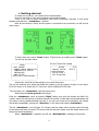
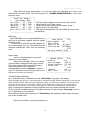
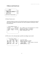
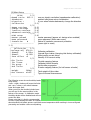
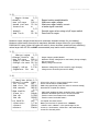
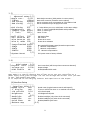
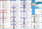
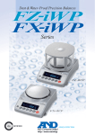
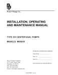
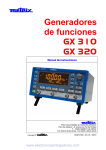
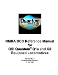
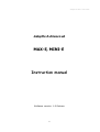
Adaptto E-drives Lab. 2013
Adaptto E-drives Lab
MAX-E, MINI-E
Instruction manual
Software version: 1.0 Release
1
Adaptto E-drives Lab. 2013
Table of Contents
1.
Getting started
2.
Main screen
3.
Menu and functions
4.
Info and error messages
5.
Health Monitor screen
6.
Stats\Watt-meter screens
7.
Connectors and pin-outs
8.
Charging and DCDC mode connection
9.
Serial number and hardware related data
2
Adaptto E-drives Lab. 2013
1. Getting started
To make your e-bike go, you need to follow several steps:
Connect controller to your motor, batteries and throttle\e-brake.
There is no need to match hall\phase wires while connecting controller to the motor
because controller has <Autodetect> function.
After all connections is done, and the power is connected to the controller you will see the
main screen:
To enter main menu press “Down” button. If Quick menu is enabled, press “Down” again.
You will see the main menu:
--------------------|
Menu
|
| >SET RANGE
|
| POWER MODE PROFILES|
| CONTROLLER SETUP
|
| INTERFACE
|
| BMS SETUP
|
| Activate SmartPower |
|
|
---------------------
Go to Controller setup
--------------------|
SETUP
1/3|
| Speed ratio: 085.4 |
|>Autodetect
|
| Direction +
|
| Calibration
|
|
|
|
|
---------------------
Speed ratio should be set according to your wheel and motor.
The you can measure your wheel and divide the number in mm by number of poles of your motor.
Ex for 9C motor in 24 wheel with 2.5 inch tire it will be 1965mm/23=85.4mm
The next step is to <Autodetect> hall and phase wires.
Wheel must be of the ground at this stage!
Enter the <Autodetect> menu by pressing “Right” button, then turn the throttle and hold it for
a while, wheel will start turning in several seconds. Be careful, it could start turning backwards and
will result in turning pedals backward as well. If you see your wheel turns backward, just release
the throttle immediately, change the <Direction> in the menu and repeat <Autodetect>.
The full <Autodetect> cycle will take 2-3 minutes, and the wheel will be turning slowly first part
of procedure and than at around 75% pwm while the last part. Please note the wheel must be off
the ground and freewheeling.
When <Autodetect> completes you will see <RetCode:001> message at the screen.
3
Adaptto E-drives Lab. 2013
After halls and phase configuration is set up and angles are calibrated it is time to set
current limits for each profile. This could be done via <POWER MODE PROFILES> menu from
the main menu:
--------------------|
Profiles Setup
|
|
|ECO|NORM |BST
|
|Ib A|10 | 25 | 100 | The first string is Battery current limit for each profile,
|Ip A|99 | 120 | 180 | Second string is for Phase current
|IprA|10 | 20 | 75 | Third string is regen phase current (regen power )
|Skph|25 | 99 | 120 | Fourth string is for speed limit
|Acc |016| 025 | 032 | Fifth string is Acceleration rise limit setting (limit your max
|
| acceleration)
--------------------BMS setup
While MAX-BMS is not connected\disabled you
still have to set battery capacity and low voltage
discharge cutoff.
You may set up both AH and WH capacity for
the current battery you use. This values could be
changed automatically while first full discharge
cycle.
Regen setup
Also it is recommended to set correct
settings for regen-braking.
When using hall effect sensor you need to
set max battery voltage and max regen current.
The brake signal could be inverted if requred.
When using regular on\off switch it is
recommended to enable <Smooth> option as
well. This will make current ramp up smooth and
will lessen the stress on dropouts.
--------------------|
BMS SETUP
1/2|
|>BMS enable
NO
|
| BMS SETUP
|
| Battery AH
10.2AH |
| Battery WH
00350Wh|
|
2/2|
| Dischg cutoff 026V |
----------------------------------------|
REGEN SETUP
1/2|
|>Enable
ON
|
| Max Voltage
098 V|
| Rated Current 35.2A|
| Inversion
N
|
|
2/2|
| Smooth
NO
|
| PWM limit
95.3%|
---------------------
Throttle/E-Brake calibration
Go to Controller setup->Calibration and set <Thr limits> (see page 7 for details)
After changing the limits it is recommended to calibrate throttle linearity, especially if you use hallsensor based throttle. After entering calibration mode, you will have to steadily turn the throttle
from min to max within 2-3 seconds 4 times. Cycles longer than 3 seconds or shorter than 2
seconds will be ignored. If the cycle is accepted, you will see the actual graph on the display.
After 4th iteration the calibration will be completed and your throttle response will be linear.
If you would like to add progression to throttle response, you may change <thr progr.> from 0
to 1-3 depending of your requests.
After setting up the throttle, please go to <Brk limits> and calibrate e-brake sensor the same
way as the throttle limits.
Now your controller is set up and ready to go!
4
Adaptto E-drives Lab. 2013
2. Main screen
The main screen displays the most important information while you drive:
1. Actual power in Watts
2. TCS (traction control system) enabled\activated
3. Current in Amps
4. Smart-Range data (when enabled)
5. Battery SOC in %
6. Speed units
7. Battery “fuel” gauge
8. Speedometer
9. Estimated remaining rage at current SOC
10. Current trip distance
11. Battery voltage
12. Motor temperature (when temperature sensor connected and enabled)
13. Temperature\Overheat current limit bar
14. Mode\info messages display (eco\normal\boost\cruise\brake\charge etc.)
15. Power bar
From the main screen you may press <down> to enter menu\quick menu,
<left> and <right> will move you to Health monitor or Stats\Watt-meter screens.
5
Adaptto E-drives Lab. 2013
3.Menu and functions
--------------------|
Menu
|
|> SET RANGE
|
| POWER MODE PROFILES|
| CONTROLLER SETUP
|
| INTERFACE
|
| BMS SETUP
|
| Activate SmartPower |
|
|
---------------------
1)
2)
3)
4)
5)
(1) Smart Power menu.
Using this feature you can set the limit of capacity you are planning to spend
per known range and the controller will limit your power to allow you reach
the destination.
--------------------| SmartRange setup
|
|>Range
010.0Km|
| Power amount 04.0Ah |
| Power range 01.3Ah |
| Go
|
|
|
|
|
|
|
---------------------
The range you are planning to cover
Amount of power to spend
Additional power allowed.
Start current trip
(2) This menu is for setting 3 power profiles according to your needs.
--------------------|
Profiles Setup
|
|
|ECO|NORM |[BST] |
|Ib A|10 | 25 | 100 |
|Ip A|99 | 120 | 180 |
|IprA|10 | 20 | 75 |
|Skph|25 | 99 | 120 |
|Acc |16 | 25 | 32
|
|
|
---------------------
profile name
battery current limit
phase current limit
regen power = regen phase current
speed limit
acceleration limit
6
Adaptto E-drives Lab. 2013
(3) Main Setup
--------------------|
SETUP
1/3|
|>Speed ratio: 085.4 |
mm per electric revolution (speedometer calibration)
| Autodetect
|
autoset halls\phase wires combination
| Direction +
|
if your wheel rotates backwards, change the direction
| Calibration
|3.1)
|
2/3|
| Regen settings
|3.2)
| Charge settings
|3.3)
| Traction settings
|3.4)
| Advanced settings
|3.5)
|
3/3|
| DCDC setup
|3.6)
| Master passwd
|
master password (appear at startup when enabled)
| Menu passsword
|
menu password (locks main menu)
| Protection
N
|
Status of hardware overcurrent protection
--------------------(press right to reset)
3.1)
--------------------|
Calibration
1/3|
|>Voltage adj 078.6v |
Voltmeter calibration
| ShuntR
0.301m |
Internal Shunt value (changing this factory calibrated)
| Shunt2
+0.00% |
Affect profile current setup
| Zero offset +0
|
Standby 0.0A current setup
|
2/3|
|>Thr limits
|
Throttle mapping feature
| Thr linear
|
Calibrate throttle linearity
| Thr progr.
1
|
Set throttle progression
| Brk limits
|
E-brake mapping feature (for hall sensor e-brake)
|
3/3|
| Weight
148Kg |
Total weight of bike+rider
|>Int TSensor KTY83 |
Type of internal thermosensor
|
|
--------------------The following screen shows throttle\e-brake
limits setup.
<left>-<right> buttons will move the limits
and <up>-<down> will switch between
lower and upper limit.
When you move the throttle\e-brake lever
you will see it’s the exact position in the
bottom of the screen. In calibration mode
throttle\e-brake will be disabled and will not
control the bike.
Please note that it is highly recommended
to leave a gap between the start of throttle/e-brake move and actual limit as shown on the picture
above because hall-effect sensors could have some temperature drift resulting in incorrect signals
processing and sudden e-bike move\braking.
7
Adaptto E-drives Lab. 2013
3.2)
--------------------|
Regen Setup
1/2|
|>Enable
ON
|
| Max Voltage
100 V|
| Rated Current 35.2A|
| Inversion
N
|
|
2/2|
| Smooth
NO
|
| PWM limit
95.3%|
|
|
---------------------
Regen braking enable\disable
Maximum regen voltage
Maximum regen battery current
e-brake signal inversion
Smooth regen when using on\off regen switch
Pwm limit for regen
Maximum regen voltage(should be set to maximum allowable voltage for your battery)
Maximum regen-brake current(set to maximum allowable charge current for your battery)
PWM limit for regen (higher the value will result in lower minimum speed but lower efficiency)
values larger than 95.3% are NOT recommended (may lead to motor overheating)
3.3)
--------------------|
Charge setup
1/2|
|>Charge Enable ON
|
| Max Voltage
100 V|
| Supply Current 35.2A|
| Charge Current 28.5A|
|
2/2|
|>Supply Vdrop
1.23V|
| ChgSensor inv NO
|
|
|
--------------------3.4)
--------------------|
TRACTION SETUP 1/3|
|>Throttle mode TORQ |
| Thr cruise
OFF |
| PWM rise lim
00016|
| SPD smooth
08192|
|
2/3|
|>2WD Enable
OFF |
| Slave SL:
24kph|
| TRK dV:
0.00#|
| TRK dA:
00000|
|
3/3|
|>LS Enable
OFF |
| LSCurrent:
3.51A|
| LSstart
05KPH|
| HSstart
10KPH|
|
|
---------------------
Regen-charging enable\disable
Maximum charge voltage(set to max battery charge voltage)
PSU current limit
Battery charge current limit
Maximum voltage drop of PSU used for regen-charging
Charge sensor inversion(reserved for OEM)
Select either speed or torque based throttle control
Cruise control feature enable\disable.
PWM rising speed limit (lower the value for smooth startup)
Smoothness of speed limit feature
2WD mode enables the slave controller when connected
Maximum allowable speed for the second controller
Traction control: acceleraton limit 0=disabled
Traction control: anti-skid feature
Low Speed slow start feature
Battery current limit for speed lower <LSstart>
<LSstart> and <HSstart> is the speed range for the
current to rise between <LSCurrent> and rated battery
current for choosed profile.
8
Adaptto E-drives Lab. 2013
3.5)
--------------------|
Advanced setup 1/5|
|>Angle corr.
-4.99°|
| Timing
+034uS|
| Ind timing
0628uS|
| PWR timing
+0.53 |
|
2/5|
|>OVS timing
007° |
|>Termosensor
YES
|
| TSensor type KTY84 |
| T° limit
180°C |
|
3/5|
|>Hall Offset
300° |
| Hall Reverse NO
|
| Wire Reverse YES
|
| Wire R, mOhm 100
|
|
4/5|
| ControlMethod SLESS |
| SIN5X
0000 |
| SIN7X
0000 |
| SIN11X
0000 |
|
5/5|
|>System Reset
|
|
|
--------------------3.6)
--------------------|
DCDC setup
1/1|
|>Current limit 9.62A|
| Voltage out
6.29V|
| DCDC Enable
NO
|
|
|
---------------------
Static Angle correction (halls position in current motor)
Static time correction (firmware version related)
Set for minimum power consumption at 75% PWM no load
Set for maximum torque at high power levels
0-7 value allows you to run a bit faster on the same voltage
Motor T° sensor Disable\Enable\Enable with prediction.
Motor T° sensor type
Motor T° limit
Hall Angle offset
Hall reverse
Phase wires revers
Phase wires resistance
Sin-wave(AUTO)\Square-wave\Sensorless square-wave
5 Harmonic compensation
7 Harmonic compensation
11 Harmonic compensation
Full system reset to factory defaults
Set Current limit (will hiccup when overcurrent detected)
Output voltage
Enable\Disable DCDC mode
DCDC mode is a special feature that allows you to use your controller as a
power supply with given voltage. You can set voltage and current limit you want
to get, than enable DCDC mode.
It is required to use charging inductor and capacitors at the output.
(4) Interface Setup
--------------------| Interface SETUP 1/2|
|>Speed Units
KPH |
Speed unuts (toggles between metric and imperial)
| t° display
OVH |
t° bar on main screen show t° or overheat current limit
| LCD refresh
0.2S |
LCD refresh speed
| Brightness
HI
|
LCD Brightness HI/LOW
|
2/2|
| BackLight
off |
Enables back-light (only when dc-dc connected)
| HeadLight
str |
Enables headlight (only when dc-dc connected)
| Quick menu
NO
|
Enables\disables Quick menu
| Buttons map
|4.1)
|
|
--------------------9
Adaptto E-drives Lab. 2013
4.1) Quick menu buttons setup
--------------------| Buttons Mapping 1/2|
|
Quick menu:
|
|> Button UP
TRK
|
| Button Left Light |
| Button Right Cruise|
|
|
|
Traction Control |
|
|
| Throttle buttons 2/2|
|> Button A
Charge|
| Button B
Light |
| Button C
Cruise|
| Button D
Horn |
|
|
|Charge enable\disable|
|
|
---------------------
Charge
Regen-Charging mode enable\disable
Cruise
Throttle Cruise enable\disable
Backwd
Reverse on\off
TSC
Traction control
LCD Br
Display brightness LOW\HIGH
2WD
2nd controller enable\disable
LS en
LS mode enable\disable
DCDC
DCDC mode on\off
Horn
Horn ON
Light
Low Beam Light on\off
HiBeam
Hi Beam Light on\off
Strobe
Strobe mode ON
StrHrn
Strobe with Horn ON
(5) BMS Setup
--------------------|
BMS SETUP
1/2|
|>BMS enable
NO
|
Max-BMS enable\disable
|>BMS SETUP
|5.1)Only when using MAX-BMS
| Battery AH
10.2AH |
Battery capacity AH
| Battery WH
00350Wh|
Battery capacity WH
|
2/2|
| Dischg cutoff 026V |
Low Voltage Discharge cutoff
|
|
---------------------
4.Info and error messages
!THR!
show when more than 4.5v appear at the throttle input.
!BMS!
show when bms enabled but not connected\misconfigured
LowBat
means your battery voltage is lower than set in BMS section
!HALLS!
means hall sensors are not connected\not workable
Cruise
shows when cruise control is active
brake
will show up while regen-braking.
Charge
will show up when regen-charging mode enabled (by pressing “up” while charging
you will go to Charge monitor)
Protect
means than over-current protection is on.
10
Adaptto E-drives Lab. 2013
5.Health Monitor
There are several parameters that could be
useful for controller setup and diagnostics.
First string: important controller voltages.
Second string: motor hall sensor voltage.
Third string: motor temperature.
Forth string: hall sensors positions.
Fifth string: service information and protection.
Last string: internal controller temperature.
6. Stats\Watt-meter
The following screen shows trip and battery statistics:
Upper left corner: current SOC (state of charge)
Current trip fom last reset
: Used power in WH
Moving time from last reset
: Used power in AH
Remaining range
: Remaining WH
Average moving speed
: Avg consumption
Maximum recorded speed
: Max consumption
Regen capacity AH
: Regen WH
Average battery voltage
: Battery iRe
To reset current trip\or set Full Charge after charging please press <up> button.
From the stats\watt-meter screen you can also go <down> to Total Statistics:
Odometer
Number of cycles
Current battery WH
Current battery AH
Current battery iRe
: Total KWH used
: Full battery cycles
: Maximum recorded WH
: Maximum recorded AH
: Minimum recorded iRe
From Total Statistics screen you can go <down> to Charge screen (also appear when you press
<up> button from the main screen in Charge mode):
Current SOC counted in WH : Charge power W
How much WH is remaining to : full charge WH
Power supply Current : Battery charge current
How much time is remaining to Full charge.
11
Adaptto E-drives Lab. 2013
7. Connectors and pin-outs
1)
2)
3)
4)
5)
6)
7)
8)
9)
Positive power lead (red housing male)
Negative power lead (black housing male)
BMS connector (red heat shrink)
Display connector (blue heat shrink)
Hall\motor connector
Negative charge lead (black housing female)
motor phase 1 (blue housing female)
motor phase 2 (blue housing female)
motor phase 3 (blue housing female)
Hall\motor connector pin-out (male motor side):
1)
2)
3)
4)
5)
6)
hall 1
hall 2
hall 3
motor temperature sensor
GND
+5v
Throttle\E-brake connector pin-out:
1)
2)
3)
4)
+5v (brown wire)
Brake hall out (white wire)
GND (black wire)
Throttle hall out (blue wire)
USB female connector
Uses regular pin-out with shorted data+ and data- for most phones compatibility.
12
Adaptto E-drives Lab. 2013
8.Charging and DCDC mode connection
To charge your battery via regen-charging mode you must connect PSU (Power Supply
Unit) to the controller via Inductor according to the following picture.
Inductor L1 must be 15-30uH with sufficient current rating (>than PSU max current)
Capacitor C1 must be 470-1000uF with voltage greater than PSU voltage
Left side of L1 connected to ANY of 3 phase wires, while they still must be connected to
the motor. Negative lead of the PSU must be connected to Negative Charging lead of the
controller (black female XT150 connector)
In charge mode when Charge is enabled and PSU connected, charging will start
automatically. For setting Charge parameters please see page 8 <Charge setup> menu.
In DC-DC mode load must be connected instead of PSU, but L1 and C1 is mandatory.
13
Adaptto E-drives Lab. 2013
10.Serial number and hardware related data
Serial Number ______________________________________________
Shunt Resistance ____________________________________________
Initial firmware version _______________________________________
Notes _____________________________________________________
__________________________________________________________
__________________________________________________________
__________________________________________________________
__________________________________________________________
__________________________________________________________
14