1
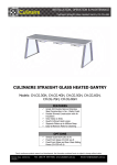
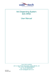
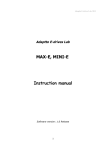
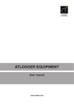
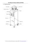
ASTA Handling System
Installation & Operating Instructions
Part #s V2HS-03, V2HS-05LS & V2HS
01/25/11
Handling System Serial #
ASTA Serial #
Date:
PRACTICAL SYSTEMS, INC.
11617 Prospect Road • Odessa, FL 33556
(800) 237-8154 • Fax (800) 330-3800
www.LookToPSI.com
ASTA Handling System
Installation & Operating Instructions
Transportation & Storage
1. The ASTA Handling System is fully inspected before leaving the manufacturer. Inspect the packaging upon arrival for any damage. Report any damage immediately to the freight company.
2. The ASTA Handling System is shipped in a wooden crate. Use a fork lift to move the crate. Make
sure it is not tilted. Keep the crate in a clean, dry area that is above freezing until ready to unpack.
Safety Precautions
• Neverattempttooperatethismachinebeforeyouhavethoroughlyreadandunderstandallthe
instructions. Keep this user’s manual on hand and review it frequently to ensure continued safe
operation.
• Turnofftheelectricalandairconnectionsbeforedoingmaintenanceorrepairsonthemachine.
• Theapplicatorisdrivenbyelectricalandpneumaticpower.
• Themachinewillonlyoperatewhentheupperlidisclosed.
• Themanufacturerdoesnotassumeanyresponsibilityorliabilityforanydamagescausedby
negligence or ignorance of the precautions in this manual or use of the machine for any purpose
other than to apply surface tape to optical lenses. Inappropriate use, installation, maintenance or
modifications to the machine will render the warranty null and void.
• MakesuretheASTAHandlingSystemisplacedonthegroundwhereitislevelandvibration-free.
• TheASTAHandlingSystemshouldonlybeoperatedbytrainedstaffwhohavereadtheoperating
manual and are at least 16 years of age.
• Makesuretheworkstationandsurroundingareaiscleanandworkerfriendly.
Operator Training
1. Train operators on the operation of the handling system as described in this manual.
2. Allow only trained employees to operate the ASTA Handling System.
3. Make sure operators have been informed of all safety measures when operating this machine.
4. Provide training at regular intervals, at least once every year.
2
ASTA Handling System Technical Information
Technical Data
Dimensions:
4’ 10” W x 3’ 5” D x 5’6” – 6’5” H (adjustable)
1470mm W x 1050mm D x 1670 – 1965mm H (adjustable)
Weight:
518 lbs. (235 kg)
Electrical:
110-240 volt AC, 50-60 HZ
Air:
filtered, compressed air
Working pressure:
72 - 82psi; 5-6 bar
Sound:
under 70 decibels
Lens Blanks:
plastic or glass
Diameters:
55-82mm
Edge height:
min. 2mm
Total height:
max. 24mm
Capacity per cycle:
2 lenses
Cycle time:
approximately 15 seconds
Productivity:
up to 400 lenses per hour
Materials:
All standard, liner or linerless surface tapes. It is recommended that you use
PSI’s double roll tape for higher efficiency (available in green or blue).
3
ASTA Handling System Parts
o
u
t
r
y
w
e
a
s
i
q
4
ASTA Handling System Parts
Parts Listing:
q
w
e
r
t
y
u
i
o
Adjustable legs - for adjusting the conveyor belt height 29.5” - 37.4” (750mm-950mm)
a
s
Main power switch -turnshandlingsystemonandoff
Automatic Surface Tape Applicator (ASTA) on swivel table
Conveyor belt with drive motor and pneumatic stops
Left side arm with four finger grab
Right side arm with four-finger grab
Doors with contact safety switch
Operation control panel - see below
Cabinet
Signal Lamp - indicates level of operation
Alarm - sounds when ASTA is out of tape
Red Light - solid - trouble has occurred; flashing - out of tape
Orange Light - jam on conveyor belt
White Light - Main Power Switch is on
Set-up control knobs - used to customize the operation of the handling system to the
owner’s needs.
uOperation control panel
f g h j
Stop Button - stops ASTA
d Emergency
and conveyor belts while in operation.
d
Button - sets the unit to home
f “Reset”
position
g “Start” Button - starts operation
h “Stop” Button - stops operation
Switch (key operated) j to“Auto/Hand”
switch between automatic and
manual operation modes.
5
ASTA Handling System Parts
t
q
ASTA Swivel Table in the operating position
k
e
y
r
w
ASTA Swivel Table in the open position
Parts Listing:
k
q
w
e
r
t
y
ASTA Swivel Table Transport Safety Device - must be removed before operating the system
ASTA Swivel Table in the operating position
ASTA Swivel Table in the open position
ASTA Transport Safety Devices - must be removed before operating the system
ASTA Reset Button
ASTA On/Off Switch
ASTA Upper Cylinder Unit
6
Installation Instructions
The ASTA Handling System is fully automated to apply protective tape to semi-finished lenses. Job
trays are transported via a conveyor belt, while robotic arms with four-finger grab pick up the lenses
and place them in the ASTA to be taped and place them back in the tray to be taken to the next station. The ASTA applies tape to plastic or glass lenses on the convex side of the lens blank. Using the
ASTA Handling System for any other purpose than applying lens tape to lenses will null and void the
warranty. To ensure proper operation, follow the instructions in this manual. Safety devices have
been designed into the handling system for the operator’s safety. Disengaging or modifying these
devices will void the warranty. Only use tape designed for lenses such as PSI’s LenSaver tapes in
single and double rolls.
Installation Instructions
1. Locate the unit where it can be hooked up to the lab’s existing conveyor belt system but also allows room for the ASTA Swivel Table to open ( w ) and provide room for the operator to perform
maintenance and change out the tape.
2. The ASTA Handling System must be level before securing the unit to the floor by screwing the 4
angled feet to the ground ( q ) .
3. Unscrew the Transport Safety Device ( k ) on the right that holds the ASTA Swivel Table ( q )
secure for shipping.
4. Once the ASTA Swivel Table’s Transport Safety Device has been removed, swing the ASTA into the
open position ( w ) so you can remove the two Transport Safety Devices ( e ) on the drawer of the
ASTA.
5. Swing the ASTA back into the operating position ( q ).
6. Hook up the appropriate electrical and air connections as specified in the Technical Specifications
Section. The hookups are located on the left side of the unit
7
Installation Instructions
Turning the ASTA Handling System On
1. Make sure the Emergency Stop Button ( d ) is not engaged. If so, release it by turning it to the
right.
2. Make sure the plexiglass doors are closed firmly ( y ).
3. Turn the Auto/Hand Switch ( j ) to AUTO.
4. Make sure the ASTA is in the operating position ( q ).
5. Make sure the ASTA Reset Button ( r ) is not pressed in. If in, press the button to release it.
6. TurntheASTAOn/OffSwitch(t )totheONposition.
7. Turn the Main Power Switch ( a ) on the handling system to “1”. The SPS control system and air
supply is now activated. The Reset Button ( f ) will flash green.
8. Press the Reset Button ( f ). The system will go to home position. The white Start Button ( g ) will
flash.
IMPORTANT:
If the red light on the Signal Lamp ( o ) does not go out, call PSI for assistance at
727-376-7900 or toll free in the US at 800-237-8154.
Turning the ASTA Handling System Off
Donotswitchthesystemoffwhileitisinoperation.
1. Press the Stop Button ( h ).
2. Turn the Main Power Switch ( a ) to “0” .
3. Perform daily cleaning and maintenance as described in the Maintenance Manual.
IMPORTANT SAFETY INFORMATION!
Emergency Stop Button
1. An Emergency Stop Button ( d ) has been provided to stop all operations immediately if necessary.
2. The Emergency Stop Button ( d ) is on the upper right of the operating panel of the ASTA Handling System.
3. When the Emergency Stop Button ( d ) is pressed, all functions of the ASTA Handling System are
immediately ceased.
4. To disengage, turn the button to the right.
8
Set-Up Instructions
Installing Liner Tape To The ASTA
Recommended liner tapes to be used with this unit are PSI’ Blue Lens Saver Tape (part #s: 1007 - single roll;
1007-1 - double roll) and PSI’s Green LensSaver Tape (part #s: 1005 - single roll; 1005-1 double roll) or Eurolens
Saver Tape (part #1400) for alloy or PSI’s Clear Tape (part #1006) for wax blocking. If you are using linerless
tape in the unit, consult the ASTA Owner’s Manual for Set-Up for Linerless Tape.
Manual Transport Button
Tape Spool (2)
Take-Up Guide (8)
Liner Take-Up Reel (1)
Take-Up Reel (7)
Drive Shaft (6)
Alignment Shaft (5) Conveyor Belt
w/tape (4)
Alignment Shaft (3)
1.
Swing the ASTA Swivel Table to the open position ( w ).
2.
Open the side doors on the ASTA.
3.
Release the fast-locks located on the inside of the upper cylinder unit. Lift the cylinder unit up and lay it
back on the housing of the machine.
4.
Lift up the take-up guide (8).
5.
Unscrew the positioning knob on the take-up reel (7) on the left side of the machine. Put an empty takeup core on the reel and screw in the knob.
6.
Remove the positioning knob from the tape spool (2) on the bottom right. Put on a roll of surfacing tape
with a liner and screw on the positioning knob.
7.
Separate the liner from the tape and position the tape onto the tape conveyor belt (4) adhesive side
down, in front of the alignment shaft (3).
8.
While holding the liner, advance the tape to the left side of the machine using the manual tape transport
button on the right.
9.
Insert the liner in the slot in the liner take-up reel (1) on the top right. Screw on the positioning knob.
10. Advance the tape to the take-up reel (7) on the left.
11. Place the end of the tape over the empty core and advance the tape to secure. Lower the take-up guide.
12. Close the upper cylinder unit and the side doors.
13. Swing the ASTA Swivel Table back into operating position ( q ).
9
Operating Instructions
Before processing check the ASTA to make sure of the following:
• TheASTAhastape.
• TheconveyorbeltiscleanandundamagedontheASTA.
• TapeisloadedcorrectlyontheconveyorbeltoftheASTA.
• Thetake-upspoolisworkingproperly.
• Cylindertopsareundamaged.
• TheSealingRing(V2A-362)onthecylindertopsiscleanandundamaged.
• Theplasticinsertinthecylindertopsiscleanandinsertedcorrectly.
• ThepositionO-Ring(V2A-361)iscleanandundamaged.
• Thepiston’sAeratorInsert(V2A-360)iscleanandundamaged.
• TheVacuumFilters(V2A-358)arecleanandundamaged.
BEFORE PROCESSING MAKE SURE OF THE FOLLOWING:
• TheASTAOn/OffSwitch(t )is“ON”.
• TheASTAisloadedwithtape.
• TheASTAisengagedintheoperatingposition(k ).
• ThehandlingsystemsMainPowerSwitch(a ) is on “I”.
• ThekeyoperatedAuto/HandSwitch(j ) is in the AUTO position.
• Therearenojobtraysontheconveyorbelt.
• ThewhiteStartButton(g ) is flashing and the red light element of the Signal Lamp ( o )isoff.
Job Trays
• UseonlyjobtraysthatmeetthespecificationsoftheASTAHandlingSystem’sconfiguration.See
available configurations on page 14.
• Makesurethejobtraysareundamagedandclean.
• Makesurethejobtrayhasacontactplate.
CAUTION: Do not use damaged job trays in the ASTA Handling System.
10
Operating Instructions
Placing the Lenses In The Job Tray
The ASTA Handling System is designed to tape round, plastic or glass lens blanks.
• Placeoneortwolensblanksperjobtray.
• Placethelenseswiththeconvexsideupintothereceptionareaofthejobtray.
• Makesureallitemsandpapersinthejobtrayarewithintheconfinesofthetrayanddonothang
over the edges.
WARNING:
Lenses not placed properly in the job tray can be damaged and may cause the
system to malfunction.
Start Processing
1. Place the job tray with the lenses on the conveyor belt ( e ) - the job tray must be placed between
the two skids.
2. Make sure the lenses are positioned on the conveyor belt based on how the handling system has
been configured. (See available configurations on page 14)
3. Turn the Auto/Hand Switch ( j ) to the AUTO position.
4. Press the Start Button ( g ) - the conveyor belt will move, taking the job tray into the handling system where the arms with four-finger grab ( r & t ) will place the lenses into the ASTA for taping
and back into the job tray.
5. After the tape has been applied, the job tray will continue down the conveyor.
6. The next job tray will be processed automatically.
SAFETY NOTE:
If any problems occur during operation, press the Emergency Stop
Button ( d ) on the Operating Control Panel ( u ) to immediately stop all functions.
Once the problem has been resolved, turn the Emergency Stop Button to the right to release.
Stop Processing
1. Press the Stop Button ( h ) - the conveyor belt will stop after the current job has finished processing. If there are no jobs in process, the conveyor belt will stop immediately.
11
Operating Instructions
Changing out tape
The red light element of the Signal Lamp flashes and an alarm sounds when the tape roll needs to be
replaced.
NOTE: To reduce tape roll change outs, utilize PSI’s Double Roll Tape. Available in PSI Green LenSaver
Tape (Part #1005-1) and PSI Blue LenSaver Tape (Part #1007-1).
1.
2.
3.
4.
Turn the key-operated Auto/Hand Switch ( j )totheHANDposition.
Replace the tape as described on page 9.
Turn the key-operated Auto/Hand Switch ( j ) to the AUTO position.
Restart the machine following the “Start Processing” instructions on the previous page.
Shutting Down At The End Of The Day
1. Press the Stop Button ( h ) - the conveyor belt will stop after the current job has finished processing. If there are no jobs in process, the conveyor belt will stop immediately.
2. Put the key-operated Auto/Hand Switch ( j )intheHANDposition.
3. SwitchtheASTAOn/OffSwitch(t )totheOFFposition.
4. Turn the Main Power Switch ( a ) to the handling system to the “0” position. The electrical and air
supplyisnowoff.
5. Perform the daily maintenance procedures on the Handling System and ASTA as described in the
owners manual.
VERY IMPORTANT - In order to keep the ASTA Handling System functioning properly and to
extend its life, daily, monthly and yearly maintenance procedures must be performed as specified
intheowner’smanuals.Failuretodosowillshortentheequipment’slifeaswellasleadtooperating malfunctions.
12
Safety Instructions for Maintenance:
1. Make sure electrical is disconnected before cleaning with any detergents.
2. Use of a vacuum cleaner and brush are recommended. Mild detergent and water may be used to
clean the machine. Do not use solvents or solvent based cleaners.
3. Maintenance operations should be carried out by a trained employee at regular intervals.
4. Somemaintenanceoperationsshouldbecarriedoutwiththemachinecompletelyshutoff.Follow all maintenance instructions carefully.
5. Make sure any electrical maintenance or repairs are performed by qualified personnel.
6. Allow only authorized trained personnel to open the cabinet.
7. Make sure the Main Power Switch ( a ) is turned to “0” before working on any elements inside the
cabinet.
8. Use a voltage meter to detect dead circuits or broken wires.
9. To avoid electrical shock, make sure the machine is grounded.
10.Fusesmustnotbepatchedorbridged.
Daily Maintenance To Be Performed On The ASTA Before Processing:
• Beforeperformingmaintenance,turntheATSAMainPowerSwitch( t )toOFF.
• Opentheuppercylinderunit( y )and make sure the interior of the cutting units are clean of debris and smooth running.
• Makesuretheshankspringhassufficienttensiontopressthecutterbladestotheoutsideofthe
bell.
• Checkthecutterbladestomakesuretheyarecleanandsharp.
CAUTION:
Worn cutter blades must be replaced. Instructions for changing out the cutter blades
can be found in the ASTA Manual.
13
14
Job Tray Configurations