1
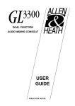
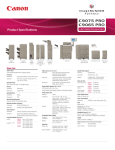
®
OPERATION and CARE MANUAL
SC-30
MCD-30
MERCHANDISING DISPLAY CASE
MODELS: MCD-30, MCD-30/P
SC-30
COOK/HOLD/SERVE SYSTEMS
W 1 6 4 N 9 2 2 1 W a t e r S t r e e t ● P.O. Box 450 ● Menomonee Falls, Wisconsin 53052-0450 U.S.A.
PHONE: 262.251.3800
FAX: 262.251.7067 • 800.329.8744 U.S.A. ONLY
WEBSITE:
800.558.8744 U.S.A./CANADA
262.251.1907 INTERNATIONAL
www.alto-shaam.com
PRINTED IN U.S.A.
#811 • 12/01
O P E R AT I O N A L P R O C E D U R E S
U N PA C K I N G a n d S E T- U P
The Alto-Shaam Display Case has
been thoroughly tested, checked for
calibration, and inspected to insure
only the highest quality unit is
provided. When you receive your
unit, check for any possible shipping
damage and report it at once to the
delivering carrier. See Transportation Damage and Claims section located
in this manual.
Save all the information and instructions packed inside
the carton. Complete and return the warranty card to the
factory as soon as possible to assure prompt service in the
event of a warranty parts and labor claim.
NOTE: Any and all claims for warranty must include the full
model number and serial number of the unit.
E L E C T R I C A L I N S TA L L AT I O N
1. An identification tag is permanently mounted on the case.
EXAMPLE
S E R I A L N U MBER AN D WAR R AN T Y C O D E
MA X IM U M R AT E D
WAT TA G E
ID EN T I F I C AT I O N MO D EL N U MBER
MODEL
xxx-xx
SERIAL NO.
VOLTS
xxx
xxxx-xx
AC
WATTS
xxxx
1 PH
xx
HZ
ALTO-SHAAM INC. MILW. WI. PAT. NO. 3521030
MA X I MU M R AT ED VO LTAG E
MAXI MU M R AT E D F R E Q U E N C Y
2. Plug the case into a properly grounded receptacle ONLY.
Arcing will occur when connecting or disconnecting the
display case unless all controls are in the “OFF” position.
3. If necessary, a proper receptacle or outlet configuration
must be installed by a licensed electrician in accordance
with applicable, local electrical codes.
Ensure Power Source
Matches Voltage Stamped
on Unit Nameplate
1. DO NOT ADD WATER TO THE DISPLAY CASE.
Halo Heat display cases maintain a constant but gentle
temperature and eliminate much of the moisture loss
associated with conventional display cases. Because of
this gentle heat, it is not necessary to add water to the
unit. As a matter of fact, adding water is not
recommended since water will accelerate the
deterioration of the product, and may damage the unit.
2. FOR MODEL MCD-30: PLACE DIVIDER BARS
AND PANS (OR PAN GRID) INTO UNIT.
The divider bars (or pan grids) must be used to close all
gaps between pans and the edges of the display case. If
these gaps are not closed, the heat can be pulled out of
the bottom of the case into the display area. As a consequence, heat distribution will be uneven and uniform
temperature will be difficult to hold. Refer to pan layout
diagrams for different types of pan accommodations that
located in this manual. Note that the pan grid is used in
the self-serve model only.
3. TURN DISPLAY LIGHTS “ON”AND SET THE
THERMOSTAT AT NUMBER "10" TO PREHEAT.
An indicator light will illuminate when the thermostat is
turned 'ON". The indicator will remain lit as long as the
unit is preheating or calling for heat. The unit should be
preheated at the number 10 setting for a minimum of 25
minutes before loading the merchandiser with food.
When preheating is completed, or whenever the unit
reaches any temperature set by the operator between 1
and 10, the indicator light will go "OUT".
4. LOAD HOT FOODS INTO THE DISPLAY CASE.
Be certain only hot food is transferred into the case.
Before loading food, use a pocket-type meat thermometer
to make certain all products have reached an internal
temperature of 140° to 160° F. (60° to 71°C). If any food
product is not at proper serving temperature, bring the
product within the correct temperature range. Be certain
only hot PREPACKAGED foods in heat tested
containers are used in the self-service section of the
display case.
.
H E AT I N G C H A R A C T E R I S T I C S
The unit is equipped with a special, low-heat-density,
heating cable. Through the Halo Heat concept, the heating
cable is mounted against the top surface of the unit to
provide an evenly applied, thermostatically controlled, heat
source. Through even heat application, food quality is
maintained up as much as several hours.
S TA RT- U P
Install the legs that are supplied with the unit. Before
operating the case, clean the interior and exterior of the unit
with a damp cloth and mild soap solution. Remove all
detachable items and clean separately. Rinse carefully.
Clean the glass with a standard commercial glass cleaner.
This unit should NOT be installed in any area where it may
be affected by steam, grease, dripping water, high
temperatures or any other severely adverse conditions. Do
not install directly adjacent to heat producing equipment.
5. RESET THERMOSTAT AS NEEDED.
After all products are loaded into the display case and the
doors are closed, reset the thermostat to the number “8”
setting. This will not necessarily be the final setting.
Since proper temperature range depends on the type of
products and the quantities being held, it is necessary to
periodically use a pocket thermometer to check each item
to make certain the correct temperatures are being
maintained. Proper temperature range is between 140°
and 160°F (60° and 71°C). Normally, this will require a
thermostat setting of between number “6” and “8,”
although a higher or lower setting may sometimes be
required.
6. SERVE FRESH HOT FOOD.
Keep hot foods looking fresh. Occasionally stir or rotate
foods as needed. Serve products in the proper package or
container. Keep display case doors closed after serving.
Wipe spills immediately to assure maximum eye appeal
and ease end of the day cleanup.
#811 Operation and Care Manual • 1.
CARE and CLEANING
14"
(356mm)
25-1/4"—(641mm)
6-3/4"
(172mm)
21-1/8 "
(537mm)
30-9/16"—(776mm)
22-1/8 "
(562mm)
o o
1"(25mm)
FOR LEGS
SC-30
SC-80
OUTSIDE DIMENSIONS
40-1/4" (1022mm)
CLEAN THE DISPLAY CASE DAILY
1. Disconnect the unit from the power source. Let unit cool.
2. Remove all detachable items such as pan separator bars,
pan grid, etc. Clean these separately.
3. Clean the interior metal surfaces of the cabinet with a
damp cloth and any good alkaline or alkaline
chlorinated based commercial detergent or grease
solvent at the recommended strength. Use a
plastic scouring pad or oven cleaner for difficult
areas. Avoid the use of abrasive cleaning
compounds, chloride based cleaners, or cleaners
containing quaternary salts. Rinse well to remove
all residue and wipe dry.
4. Clean all window areas with a standard commercial glass
cleaner.
5. To help maintain the protective film coating on polished
steel, clean the exterior of the cabinet with a cleaner
recommended for stainless steel surfaces. Spray the
cleaning agent on a clean cloth and wipe with the grain of
the stainless steel.
NOTE: Never use hydrochloric acid (muriatic acid) on
stainless steel.
Always follow appropriate state and local health (hygiene)
regulations regarding all applicable cleaning and sanitation
requirements for equipment.
At no time should the inside or
outside of the cabinet be washed
down, flooded with water or liquid
solution.
30-5/8" (778mm)
3-1/4"
(83mm)
Do not use water jet to clean.
NEVER STEAM CLEAN.
Severe damage or electrical hazard
could result, voiding the warranty.
23-1/8"
(587mm)
MCD-30
MCD-30/P
25" (635mm)
4" (102mm)
FOR LEGS
2-3/4" (70mm)
MCD-750
MCD-750/GP
36-7/8" (935mm)
50-7/16" (1281mm)
This units performance has been
optimized using the factory provided
bulbs. These bulbs should be
replaced with an exact
replacement or with a factory
recommended replacement. These bulbs have
been treated to resist breakage and
must be replaced with similarly
treated bulbs in order to maintain
compliance with NSF standards.
57-3/16" (1473mm)
SAFETY ALERT
3-1/2" (89mm)
TO CORD
6-3/4"
(171mm)
#811 Operation and Care Manual • 2.
3/4" (19mm)
55-1/4" —( 1403mm)
48-1/2" — (1232mm)
21-1/16"
(535-mm)
The cleanliness and appearance of this unit
will contribute considerably to operating
efficiency and savory, appetizing food. Good
equipment that is kept clean works better and
lasts longer.
S A N I TAT I O N G U I D E L I N E S
Food flavor and aroma are usually so closely related that
it is difficult, if not impossible, to separate them. There is also
an important, inseparable relationship between cleanliness
and food flavor. Cleanliness, top operating efficiency, and
appearance of equipment contribute considerably to savory,
appetizing foods. Good equipment that is kept clean, works
better and lasts longer.
Most food imparts its own particular aroma and many
foods also absorb existing odors. Unfortunately, during this
absorption, there is no distinction between GOOD and BAD
odors. The majority of objectionable flavors and odors
troubling food service operations are caused by bacteria
growth. Sourness, rancidity, mustiness, stale or other OFF
flavors are usually the result of germ activity.
The easiest way to insure full, natural food flavor is
through comprehensive cleanliness. This means good control
of both visible soil (dirt) and invisible soil (germs). A
thorough approach to sanitation will provide essential
cleanliness. It will assure an attractive appearance of
equipment, along with maximum efficiency and utility.
More importantly, a good sanitation program provides one of
the key elements in the prevention of food-borne illnesses.
A controlled holding environment for prepared foods is
just one of the important factors involved in the prevention of
food-borne illnesses. Temperature monitoring and control
during receiving, storage, preparation, and the service of
foods are of equal importance.
The most
INTERNAL FOOD PRODUCT TEMPERATURES
accurate
method of
HOT FOODS
DANGER ZONE
40° TO 140°F
(4° TO 60°C)
measuring
CRITICAL ZONE
70° TO 120°F
(21° TO 49°C)
safe
SAFE ZONE
140° TO 165°F
(60° TO 74°C)
temperaCOLD FOODS
tures of
DANGER ZONE
ABOVE 40°F
(ABOVE 4°C)
SAFE ZONE
36°F TO 40°F
(2°C TO 4°C)
both hot
and cold
FROZEN FOODS
DANGER ZONE
ABOVE 32°F
(ABOVE 0°C)
foods is by
CRITICAL ZONE
0° TO 32°F
(-18° TO 0°C)
internal
SAFE ZONE
0°F OR BELOW
(-18°C OR BELOW)
product
temperature. A quality thermometer is an effective tool for
this purpose, and should be routinely used on all products
that require holding at a specific temperature.
A comprehensive sanitation program should focus on the
training of staff in basic sanitation procedures. This includes
personal hygiene, proper handling of raw foods, cooking to a
safe internal product temperature, and the routine
monitoring of internal temperatures from receiving through
service.
Most food-borne illnesses can be prevented through
proper temperature control and a comprehensive program of
sanitation. Both these factors are important to build quality
service as the foundation of customer satisfaction. Safe food
handling practices to prevent food-borne illness is of critical
importance to the health and safety of our customers.
HACCP, an acronym for Hazard Analysis (at) Critical
Control Points, is a quality control program of operating
procedures to assure food integrity, quality, and safety.
Taking steps necessary to augment food safety practices are
both cost effective and relatively simple. While HACCP
guidelines go far beyond the scope of this manual, additional
information is available by contacting the USDA/FDA Foodborne Illness Education Information Center at (301)504-6803.
GENERAL HOLDING GUIDELINES
Chefs, cooks and other specialized food service
personnel employ varied methods of cooking. Proper
holding temperatures for a specific food product must be
based on the moisture content of the product, product
density, volume, and proper serving temperatures. Safe
holding temperatures must also be correlated with
palatability in determining the length of holding time for a
specific product.
Halo Heat maintains the maximum amount of product
moisture content without the addition of water, water vapor,
or steam. Maintaining maximum natural product moisture
preserves the natural flavor of the product and provides a
more genuine taste. In addition to product moisture
retention, the gentle properties of Halo Heat maintain a
consistent temperature throughout the unit without the
necessity of a heat distribution fan, thereby preventing
further moisture loss due to evaporation or dehydration.
In an enclosed holding environment, too much moisture
content is a condition which can be relieved. A product
achieving extremely high temperatures in preparation must
be allowed to decrease in temperature before being placed in
a controlled holding atmosphere. If the product is not
allowed to decrease in temperature, excessive condensation
will form increasing the moisture content on the outside of
the product.
Most Halo Heat Holding Equipment is provided with a
thermostat control between 60° and 200°F (16° to 93°C). If the
unit is equipped with vents, close the vents for moist holding
and open the vents for crisp holding.
If the unit is equipped with a thermostat indicating a
range of between 1 and 10, use a metal-stemmed indicating
thermometer to measure the internal temperature of the
product(s) being held. Adjust the thermostat setting to
achieve the best overall setting based on internal product
temperature.
HOLDING TEMPERATURE RANGE
MEAT
BEEF ROAST — Rare
BEEF ROAST — Med/Well Done
BEEF BRISKET
CORN BEEF
PASTRAMI
PRIME RIB — Rare
STEAKS — Broiled/Fried
RIBS — Beef or Pork
VEAL
HAM
PORK
LAMB
POULTRY
CHICKEN — Fried/Baked
DUCK
TURKEY
GENERAL
FISH/SEAFOOD
FISH — Baked/Fried
LOBSTER
SHRIMP — Fried
BAKED GOODS
BREADS/ROLLS
MISCELLANEOUS
CASSEROLES
DOUGH — Proofing
EGGS —Fried
FROZEN ENTREES
HORS D'OEUVRES
PASTA
PIZZA
POTATOES
PLATED MEALS
SAUCES
SOUP
VEGETABLES
FAHRENHEIT
CELSIUS
140°F
160°F
160° — 175°F
160° — 175°F
160° — 175°F
140°F
140° — 160°F
160°F
160° — 175°F
160° — 175°F
160° — 175°F
160° — 175°F
60°C
71°C
71° — 79°C
71° — 79°C
71° — 79°C
60°C
60° — 71°C
71°C
71° — 79°C
71° — 79°C
71° — 79°C
71° — 79°C
160°
160°
160°
160°
71°
71°
71°
71°
—
—
—
—
175°F
175°F
175°F
175°F
—
—
—
—
79°C
79°C
79°C
79°C
160° — 175°F
160° — 175°F
160° — 175°F
71° — 79°C
71° — 79°C
71° — 79°C
120° — 140°F
49° — 60°C
160° — 175°F
80° — 100°F
150° — 160°F
160° — 175°F
160° — 180°F
160° — 180°F
160° — 180°F
180°F
180°F
140° — 200°F
140° — 200°F
160° — 175°F
71°
27°
66°
71°
71°
71°
71°
— 79°C
— 38°C
— 71°C
— 79°C
— 82°C
— 82°C
— 82°C
82°C
82°C
60° — 93°C
60° — 93°C
71° — 79°C
THE HOLDING TEMPERATURES LISTED ARE SUGGESTED GUIDELINES ONLY.
#811 Operation and Care Manual • 3.
PA NCONFIGURATIONS
C O N F I G U R AT I O N S
PAN
MMCD-30
CD-30
FULL-SIZE PAN
FULL-SIZE PAN
#1455
FULL-SIZE PAN
#1455
ONE-HALF
SIZE PAN
1: #1338
ONE-HALF
SIZE PAN
ONE-HALF
SIZE PAN
#1455
20"—(508mm)
26-1/4"—(667mm)
ONE-THIRD
SIZE PAN
ONE-HALF
SIZE PAN
FULL-SIZE PAN
2: #1338
ONE-HALF
SIZE PAN
1: #1338
ONE-HALF
SIZE PAN
#1455
ONE-HALF
SIZE PAN
#1455
1: #1338
ONE-THIRD
SIZE PAN
ONE-THIRD
SIZE PAN
ONE-THIRD
SIZE PAN
ONE-THIRD
SIZE PAN
ONE-THIRD
SIZE PAN
ONE-THIRD
SIZE PAN
ONE-THIRD
SIZE PAN
ONE-THIRD
SIZE PAN
ONE-THIRD
SIZE PAN
3: #1338
ONE-HALF
SIZE PAN
1: #1472
1: #1473
#1455
2: #1338
ONE-THIRD
SIZE PAN
2: #1338
AAAAAAAAAA
AAAAAAAAAA
A
A
A
A
A
A
A
A
FULL-SIZE SHEET PAN
ONE-THIRD
SIZE PAN
STANDARD PAN DIVIDER BARS
ITEM
DESCRIPTION
QTY
1455
FULL, HALF & THIRD SIZE PANS (LONG)
1
1472
SHEET PAN (LONG)
1
1473
SHEET PAN (SHORT)
1
11318
FULL, HALF & THIRD SIZE PANS (SHORT)
4
STANDARD PAN SIZES
FULL SIZE PANS
12" x 20" x 4"
12" x 20" x 2-1/2"
GASTRONORM PANS
325mm x 530mm x100mm
325mm x 530mm x 65mm
GN 1/1
GN 1/1
325mm x 265mm x100mm
325mm x 265mm x 65mm
GN 1/2
GN 1/2
325mm x 176mm x100mm
325mm x 176mm x 65mm
GN 1/3
GN 1/3
ONE-HALF SIZE PANS
12" x 10" x 4"
12" x 10" x 2-1/2"
ONE-THIRD SIZE PANS
12" x 6" x 4"
12" x 6" x 2-1/2"
FULL-SIZE SHEET PANS
18" x 26" x 1"
#811 Operation and Care Manual • 4.
N/A
M C D - 3 0 • C U S T O M E R H E AT G U A R D
I N S TA L L AT I O N I N S T R U C T I O N S
#811 Operation and Care Manual • 5.
S E RV I C E V I E W PA RT S L I S T S
MCD-30
5/3/00
PART DESCRIPTION
MCD-30/P
UNIT
ALTO-SHAAM
QUANTITY PART NUMBER
1.
LEGS
4
LG-2044
2.
BOTTOM
1
4451
3.
BOTTOM MOUNTING SCREWS
4.
INSULATION: 24” x 29” (610mm x 737mm)
5.
CABLE CONNECTION HARDWARE
6.
HEATING CABLE (length): 63’ (19202mm)
1
CB-3045
7.
THERMOSTAT
THERMOSTAT KNOB
1
1
TT-3498
KN-3473
8.
INDICATOR LIGHT (125V)
INDICATOR LIGHT (230V)
1
1
LI-3027
LI-3025
9.
LIGHT SWITCH
1
SW-3616
10.
POWER “ON” SWITCH
1
SW-3041
11.
CORD & PLUG SET (125V)
BUSHING (NOT SHOWN)
CORD (230V) 6’ (1829mm)
1
1
1
CD-3397
BU-3311
CD-3031
12.
OUTER TOP
1
4168
13.
OUTER TOP MOUNTING SCREWS
4
SC-2459
14.
BULB (120V)
BULB (230V)
6
6
LP-3542
LP-3543
15.
BULB RECEPTACLES (125V)
O-RING (125V)
BULB RECEPTACLES (230V)
6
6
6
RP-3952
SA-22377
RP-3955
16.
FRONT GUARD
1
GD-22123
17.
LIGHT GUARD
1
GD-22124
18.
FRONT GLASS (CUSTOMER SIDE)
1
GL-2706
19.
END GLASS
2
GL-22126
20.
DOOR, LEFT-HAND
DOOR HINGE, LEFT-HAND
DOOR HINGE, LEFT-HAND
1
2
2
5894
HG-22169
HG-22167
DOOR, RIGHT-HAND
DOOR HINGE, RIGHT-HAND
DOOR HINGE, RIGHT-HAND
1
2
2
5895
HG-22170
HG-22168
22.
HANDLE
2
HD-2910
23.
CONTROL PANEL OVERLAY
CONTROL PANEL MOUNTING SCREWS
1
6
PE-2978
SC-2459
24.
PAN DIVIDER BARS (NOT SHOWN)
—FULL, HALF & THIRD SIZE (LONG)
—SHEET PAN (LONG)
—SHEET PAN (SHORT)
—FULL, HALF & THIRD SIZE (SHORT)
1
1
1
4
1455
1472
1473
11318
OPTIONS (NOT SHOWN)
MIRRORED GLASS DOOR ASSEMBLY, LEFT HAND
MIRRORED GLASS DOOR ASSEMBLY, RIGHT HAND
1
1
14469
14470
21.
25.
Disconnect Unit
From Power Source
Before Cleaning and
Servicing
12
SC-2425
1
IN-22364
5/3/00
PART DESCRIPTION
UNIT
ALTO-SHAAM
QUANTITY PART NUMBER
1.
LEGS
4
LG-2044
2.
BOTTOM
1
4451
3.
BOTTOM MOUNTING SCREWS
4.
INSULATION: 24” x 29” (610mm x 737mm)
5.
CABLE CONNECTION HARDWARE
6.
12
SC-2425
1
IN-22364
HEATING CABLE (length): 63’ (19202mm)
1
CB-3045
7.
THERMOSTAT
THERMOSTAT KNOB
1
1
TT-3498
KN-3473
8.
INDICATOR LIGHT (125V)
INDICATOR LIGHT (230V)
1
1
LI-3027
LI-3025
9.
LIGHT SWITCH
1
SW-3616
10.
POWER “ON” SWITCH
1
SW-3041
11.
CORD & PLUG SET (125V)
BUSHING (NOT SHOWN)
CORD (230V) 6’ (1829mm)
1
1
1
CD-3397
BU-3311
CD-3031
12.
OUTER TOP
1
4168
13.
OUTER TOP MOUNTING SCREWS
4
SC-2459
14.
BULB (120V)
BULB (230V)
6
6
LP-3542
LP-3543
15.
BULB RECEPTACLES (125V)
O-RING (125V)
BULB RECEPTACLES (230V)
6
6
6
RP-3952
SA-22377
RP-3955
16.
FRONT GUARD
1
GD-22360
17.
LIGHT GUARD
1
GD-22124
18.
FRONT GLASS (CUSTOMER SIDE)
1
GL-22362
19.
END GLASS
2
GL-22126
20.
DOOR, LEFT-HAND
DOOR HINGE, LEFT-HAND
DOOR HINGE, LEFT HAND
1
2
2
5894
HG-22169
HG-22167
21.
DOOR, RIGHT HAND
DOOR HINGE, RIGHT-HAND
DOOR HINGE, RIGHT-HAND
1
2
2
5895
HG-22170
HG-22168
22.
HANDLE
2
HD-2910
23.
CONTROL PANEL OVERLAY
CONTROL PANEL MOUNTING SCREWS
1
6
PE-2878
SC-2459
24.
PAN GRID (NOT SHOWN)
1
PN-2115
25.
OPTIONS (NOT SHOWN)
MIRRORED GLASS DOOR ASSEMBLY, LEFT-HAND
MIRRORED GLASS DOOR ASSEMBLY, RIGHT HAND
1
1
14469
14470
SERVICE VIEWS • See following pages.
#811 Operation and Care Manual • 6.
#811 Operation and Care Manual • 7.
#811 Operation and Care Manual • 8.
SERVICE VIEW PARTS LIST
5-3-00
SAFETY ALERT
SC-30
Part Description
Qty.
This units performance has been
optimized using the factory provided
bulbs. These bulbs should be
replaced with an exact
replacement or with a factory
recommended replacement. These bulbs have
been treated to resist breakage and
must be replaced with similarly
treated bulbs in order to maintain
compliance with NSF standards.
Alto-Shaam
Part No.
1. LEGS, 1" (25mm)
4
LG-2043
2. BOTTOM ASSEMBLY
1
4502
3. BOTTOM ASSEMBLY MOUNTING SCREWS
14
SC-2459
4. INSULATION:
-SIZE: 24-1/2" X 30" (622mm x 762mm)
1
IN-2381
5. ELEMENT CLAMP
1
1761
6. ELEMENT CLAMP MOUNTING SCREWS
2
SC-2459
7. BUTT CONNECTOR
2
CR-3067
8. HEATING CABLE ELEMENT
1
CB-3524
9. THERMOSTAT
THERMOSTAT KNOB
1
1
TT-3978
KN-3473
10. HEAT INDICATOR LIGHT, 125V
HEAT INDICATOR LIGHT, 220V
1
1
LI-3027
LI-3025
11. POWER SWITCH
1
SW-3041
12. LIGHT SWITCH
1
SW-3616
13. CORD & PLUG SET, 125V
CORD, 220V, 6' (1829mm)
1
1
CD-3232
CD-3508
14. TOP
1
1064
15. TOP MOUNTING SCREWS
4
SC-2459
16. BULB, 120V
BULB, 220V
4
4
LP-3542
LP-3543
17. BULB SOCKET, 125V
BULB SOCKET, 220V
4
4
RP-3952
RP-3955
18. SNEEZE GUARD ASSEMBLY
WINDOW LATCH
WINDOW LATCH MOUNTING SCREWS
1
6
6
4507
LT-2195
SC-2472
19. FRONT GLASS ASSEMBLY
WINDOW LATCH
WINDOW LATCH MOUNTING SCREWS
1
2
2
4506
LT-2195
SC-2472
20. ADJUSTABLE RACK
1
SR-2673
21. CHUTE DIVIDERS
CHUTE DIVIDER MOUNTING SCREWS
4
4
1979
SC-2459
22. CONTROL PANEL OVERLAY
1
PE-2855
Cable Heating Service Kit . . . . . . . . . . . . . . . . . . . . . . . . . . . . . . 4878
includes:
CB-3045
CR-3226
IN-3488
BU-3105
BU-3106
SL-3063
TA-3540
ST-2439
NU-2215
BX-2588
BX-2591
Cable Heating Element . . . . . . . . . . . . . . . . . . . . . . . . . . 72 feet
Ring Connector . . . . . . . . . . . . . . . . . . . . . . . . . . . . . . . . . . . . . 4
Insulation Corner . . . . . . . . . . . . . . . . . . . . . . . . . . . . . . . 1 foot
Shoulder Bushing . . . . . . . . . . . . . . . . . . . . . . . . . . . . . . . . . . . 4
Cup Bushing . . . . . . . . . . . . . . . . . . . . . . . . . . . . . . . . . . . . . . . 4
Insulating Sleeve . . . . . . . . . . . . . . . . . . . . . . . . . . . . . . . . . . . . 4
High Temperature Tape. . . . . . . . . . . . . . . . . . . . . . . . . . 1 foot
Stud, 10/32. . . . . . . . . . . . . . . . . . . . . . . . . . . . . . . . . . . . . . . . . 4
Hex Nut . . . . . . . . . . . . . . . . . . . . . . . . . . . . . . . . . . . . . . . . . . . 8
Cable Box . . . . . . . . . . . . . . . . . . . . . . . . . . . . . . . . . . . . . . . . . . 1
Cable Box . . . . . . . . . . . . . . . . . . . . . . . . . . . . . . . . . . . . . . . . . . 1
Disconnect Unit
From Power Source
Before Cleaning and
Servicing
MCD-30 Options & Accessories
SERVICE VIEW • See following page.
SC-30 Options & Accessories
Chute Dividers . . . . . . . . . . . . . . . . . . . . . . . . . . . . . .SR-2673
For System Bases:
Legs, 6" (152mm) . . . . . . . . . . . . . . . . . . . . . . . . . . . . . . . .5205
Shelves, Chrome Plated Wire
– 750-GDU or CTUS reach-in angled . . . . . . . . . . .SH-2851
– 750-GDU reach-in, flat . . . . . . . . . . . . . . . . . . . . . .SH-2114
– 750-GDU/PT pass-thru, flat . . . . . . . . . . . . . . . . .SH-2114
Wire Pan Grid . . . . . . . . . . . . . . . . . . . . . . . . . . . . . . .PN-2115
Custom Panels . . . . . . . . . . . . . . . . . . . . . . . . . .FACTORY QUOTE
Doors, reflective tempered glass . . . . . . . . . . . . . . .GL-23487
Glass, End, mirrored, tempered, RH . . . . . . . . . . . .GL-24121
Glass, End, mirrored, tempered, LH . . . . . . . . . . .LGL-24122
Pan Separator Bars
– full/half/third size (long) . . . . . . . . . . . . . . . . . . . . . . .1455
– full/half/third size (short) . . . . . . . . . . . . . . . . . . . . . . .1473
– sheet pan separators . . . . . . . . . . . . . . . . . . . . . . .1472/1473
Menu Board . . . . . . . . . . . . . . . . . . . . . . . . . . . . . . . .MB-23091
Mirrored Glass Doors:
– Left-hand assembly . . . . . . . . . . . . . . . . . . . . . . . . . . . .14469
– Right-hand assembly . . . . . . . . . . . . . . . . . . . . . . . . . .14470
Self-serve pan grid . . . . . . . . . . . . . . . . . . . . . . . . . . . .PN-2115
#811 Operation and Care Manual • 9.
#811 Operation and Care Manual • 10.
#811 Operation and Care Manual • 11.
#811 Operation and Care Manual • 12.
#811 Operation and Care Manual • 13.
#811 Operation and Care Manual • 14.
T R A N S P O RTAT I O N
DAMAGE and CLAIMS
All Alto-Shaam equipment is
sold F.O.B. shipping point,
and when accepted by the
carrier, such shipments
become the property of
the consignee.
Should damage occur in shipment, it is a matter between the carrier
and the consignee. In such cases, the carrier is assumed to be
responsible for the safe delivery of the merchandise, unless
negligence can be established on the part of the shipper.
L I M I T E D WA R R A N T Y
Alto-Shaam, Inc. warrants to the original purchaser that any original
part that is found to be defective in material or workmanship will, at
our option, subject to provisions hereinafter stated, be replaced with
a new or rebuilt part.
The labor warranty remains in effect one (1) year from installation or
fifteen (15) months from the shipping date, whichever occurs first.
The parts warranty remains in effect one (1) year from installation or
fifteen (15) months from the shipping date, whichever occurs first.
Exceptions to the one year part warranty period are as listed:
A. Halo Heat cook/hold ovens include a five (5) year parts warranty
on the heating element. Labor will be covered under the terms of
the standard warranty period of one (1) year or fifteen (15) months.
1. Make an immediate inspection while the equipment is still in
the truck or immediately after it is moved to the receiving area.
Do not wait until after the material is moved to a storage area.
B. Alto-Shaam Quickchillers include a five (5) year parts warranty
on the refrigeration compressor. Labor will be covered under the
terms of the standard warranty period of one (1) year or fifteen
(15) months.
2. Do not sign a delivery receipt or a freight bill until you have
made a proper count and inspection of all merchandise received.
This warranty does not apply to:
3. Note all damage to packages directly on the carrier’s delivery
receipt.
4. Make certain the driver signs this receipt. If he refuses to sign,
make a notation of this refusal on the receipt.
5. If the driver refuses to allow inspection, write the following on
the delivery receipt:
Driver refuses to allow inspection of
containers for visible damage.
6. Telephone the carrier’s office immediately upon finding
damage, and request an inspection. Mail a written confirmation
of the time, date, and the person called.
7. Save any packages and packing material for further inspection
by the carrier.
1.
Calibration
2.
Replacement of light bulbs and/or the replacement of display
case glass due to damage of any kind.
3.
Equipment damage caused by accident, shipping, improper
installation or alteration.
4.
Equipment used under conditions of abuse, misuse, carelessness
or abnormal conditions.
5.
Any losses or damage resulting from malfunction, including loss
of product or consequential or incidental damages of any kind.
6.
Equipment modified in any manner from original model,
substitution of parts other than factory authorized parts,
removal of any parts including legs, or addition of any parts.
This warranty is exclusive and is in lieu of all other warranties,
expressed or implied, including the implied warranties of
merchantability and fitness for purpose. In no event shall the
Company be liable for loss of use, loss of revenue, or loss of product
or profit, or for indirect or consequential damages. This warranty is
in lieu of all other warranties expressed or implied and Alto-Shaam,
Inc. neither assumes or authorizes any persons to assume for it any
other obligation or liability in connection with Alto-Shaam
equipment.
8. Promptly file a written claim with the carrier and attach copies
of all supporting paperwork.
ALTO-SHAAM, INC.
We will continue our policy of assisting our customers in collecting
claims which have been properly filed and actively pursued. We
cannot, however, file any damage claims for you, assume the
responsibility of any claims, or accept deductions in payment for
such claims.
Record the model and serial numbers of the unit for easy reference.
Always refer to both model and serial numbers in your
correspondence regarding the unit.
Model: _____________________________________________
Serial Number: _______________________________________
Purchased From: ______________________________________
Date Installed: ____________
Voltage: ________________
Warranty effective January 1, 2000
HALO HEAT COOK/HOLD/SERVE SYSTEMS BY
W164 N9221 Water Street
PHONE:
262.251.380 0
800.558.87 4 4 U . S . A ./ C A N A D A
●
®
P.O. Box 450 ● Menomonee Falls, Wisconsin 53052-0450 ● U.S.A.
FAX:
2 6 2 . 2 5 1 . 7 0 6 7 ● 8 0 0 . 3 2 9 . 8 7 4 4 U . S . A ./ C A N A D A
WEBSITE:
262.251.1907 INTERNATIONAL
W W W .alto-shaam.com
PRINTED IN U.S.A.