1
Release Note
Software Release 2.6.4
For AT-8600, AT-8700XL, AT-8800, Rapier, and Rapier i
Series Switches
Introduction ...................................................................................................... 3
Upgrading to Software Release 2.6.4 ................................................................ 3
Hardware Platforms .......................................................................................... 4
New platform - AT-8600 Series switch ........................................................ 4
Overview of New Features ................................................................................ 5
NEBS Compliant Models ................................................................................... 6
Importing BGP routes into OSPF ........................................................................ 6
Enabling BGP route import ......................................................................... 6
Limiting the number of routes .................................................................... 6
Advertising desired routes .......................................................................... 7
Configuration example ............................................................................... 7
SNMPv3 ............................................................................................................ 8
Stacking ........................................................................................................... 8
What is Stacking? ....................................................................................... 8
Topologies .................................................................................................. 8
How Stacking Works .................................................................................. 9
ICMP Router Discovery Advertisements ............................................................. 9
Router Discovery Process ............................................................................ 9
Router Advertisement Messages ............................................................... 10
Router Solicitation Messages .................................................................... 10
Router Advertisement Interval .................................................................. 10
Preference Level ....................................................................................... 11
Lifetime .................................................................................................... 11
Configuration Procedure .......................................................................... 11
Support for Long File Names (DOS 28.3) ......................................................... 12
Upgrading to new software releases ......................................................... 12
Regressing to previous software releases .................................................. 13
Testing Asynchronous and Switch Ports ........................................................... 13
Interrupting Text Flow with the CLI ................................................................. 13
Disable 10/100 Ports at the Hardware Level .................................................... 14
Specifying the Mode of Operation When IGMP Snooping is Enabled ............... 14
IP Route Filter Changes to Protocol Parameter ................................................. 15
Remote Security Officer (RSO) Login ................................................................ 16
Remote Security Officer Login and IPv4 Only ............................................ 16
Remote Security Officer Login, IPv4 and IPv6 ............................................ 16
Enable IPV6 MLD Interface Command ............................................................. 17
Text Message at Login (Welcome banner) ........................................................ 17
Private VLANs ................................................................................................. 18
Software Release 2.6.4
2
Membership Rules for Private VLANs ........................................................
Private VLANs on Rapier 48i Switches .......................................................
Configuring Private VLANs .......................................................................
Modified Commands ................................................................................
Configuration Example .............................................................................
Probing IP Addresses .......................................................................................
Virtual Bridge (VLAN) MIB ...............................................................................
Valid Values for IPv6 Router Advertisement AdvRetransTimer ..........................
Valid Characters for File Names - Show File and Delete File Commands ...........
Extended Show Debug Command ..................................................................
Extended Syslog Format ..................................................................................
TACACS+ Authentication and Telnet ...............................................................
Adopting the VRRP IP Address ........................................................................
Benefits of VRRP IP Address Adoption ......................................................
Risks of VRRP IP Address Adoption ...........................................................
Recommendations ....................................................................................
Configuration of VR IP Address Adoption .................................................
BCP Option 8 ..................................................................................................
Firewall Enhancements ....................................................................................
ICMP protocol for firewall policy rule ........................................................
Debug and display firewall ARP requests ...................................................
Software Release 2.6.4
C613-10404-00 REV A
19
20
20
21
22
23
24
25
25
26
28
29
30
30
30
30
31
32
32
32
32
Software Release 2.6.4
3
Introduction
Allied Telesyn announces the release of Software Release 2.6.4 for the AT-8600,
AT-8700XL, AT-8800, Rapier, and Rapier i Series switches. To see which new
features and enhancements apply to each product type, see Overview of New
Features on page 5.
This Release Note describes:
■
important factors you need to consider when upgrading to Software
Release 2.6.4 from an earlier software release, in Upgrading to Software
Release 2.6.4 on page 3
■
the names of the software release, GUI and help files for this release, in
Upgrading to Software Release 2.6.4 on page 3
■
the new and existing hardware platforms supported by Software Release
2.6.4
■
the new features in Software Release 2.6.4 since Software Release 2.6.1
This Release Note should be read in conjunction with the Quick Install Guide,
User Guide, Hardware Reference, and Software Reference for your switch.
These documents can be found on the Documentation and Tools CD-ROM
packaged with your switch, or at:
www.alliedtelesyn.co.nz/documentation/documentation.html
WARNING: Information in this Release Note is subject to change without
notice and does not represent a commitment on the part of Allied Telesyn
International. While every effort has been made to ensure that the information
contained within this document and the features and changes described are
accurate, Allied Telesyn International can not accept any type of liability for
errors in, or omissions arising from the use of this information.
Upgrading to Software Release 2.6.4
Software Release 2.6.4 is available as a flash release that can be downloaded
directly from the Software Updates area of the Allied Telesyn web site at:
www.alliedtelesyn.co.nz/support/updates/patches.html
Software releases must be licenced and require a password to activate. To
obtain a licence and password, contact your authorised Allied Telesyn
distributor or reseller.
The files included in this software release are shown in Table 1.
Table 1: File names for Software Release 2.6.4
Product name
Software release file
GUI resource file
CLI help file
AT-8624T/2M
sr-264.rez
dsr24e10.rsc
SR-264A.HLP
AT-8724XL
87-264.rez
d8724e04.rsc
8700264A.HLP
AT-8748XL
87-264.rez
d8748e04.rsc
8700264A.HLP
AT-8824
86s-264.rez
d8824e10.rsc
8800264A.HLP
Software Release 2.6.4
C613-10404-00 REV A
4
Release Note
Table 1: File names for Software Release 2.6.4 (Continued)
Product name
Software release file
GUI resource file
CLI help file
AT-8848
86s-264.rez
d8848e04.rsc
8800264A.HLP
Rapier G6
86s-264.rez
d_rg6e04.rsc
RP-264A.HLP
Rapier G6F
86s-264.rez
drg6fe04.rsc
RP-264A.HLP
Rapier 16F
86s-264.rez
dr16fe04.rsc
RP-264A.HLP
Rapier 16Fi
86s-264.rez
dr16ie04.rsc
RP-264A.HLP
Rapier 24
86s-264.rez
d_r24e04.rsc
RP-264A.HLP
Rapier 24i
86s-264.rez
dr24ie04.rsc
RP-264A.HLP
Rapier 48
86s-264.rez
d_r48e04.rsc
RP-264A.HLP
Rapier 48i
86s-264.rez
dr48ie04.rsc
RP-264A.HLP
AT-RP24i/DS3
86s-264.rez
dr24ie04.rsc
RP-264A.HLP
Hardware Platforms
Software Release 2.6.4 supports the following existing hardware platforms:
■
AT-8700XL Series switches
■
AT-8800 Series switches
■
Rapier Series switches
■
Rapier i Series switches
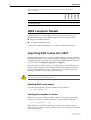
New platform - AT-8600 Series switch
Allied Telesyn announces the AT-8600 Series Advanced Fast Ethernet Switches.
These switches are available in 2004 with Software Release 2.6.4. There is
currently one model in the AT-8600 Series:
■
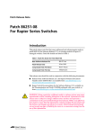
AT-8624T/2M has 24 ports with 10BASE-T/100BASE-TX RJ-45 connectors
(see Figure 1).
This switch:
•
has 2 expansion module bays.
•
includes the AlliedWare features available in Software Release 2.6.4. For
details, see Table 2 on page 5.
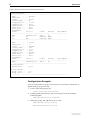
Figure 1: Front and rear panels of the AT-8624T/2M
1
3
5
7
9
11
13
15
17
19
21
23
AT-8624T/2M Advanced Fast Ethernet Switch
1
25
26
2
4
6
8
10
12
14
16
18
20
22
24
3
5
7
9
11
13
15
17
19
21
23
MODE
RS-232
TERMINAL PORT
STATUS
LINK
COL
MODE
100
LINK
FULL
RPS
MODE
ACT
PWR
2
4
6
8
10
12
14
16
18
20
22
FAULT
MASTER
24
Contact your authorised distributor or reseller for ordering information.
Software Release 2.6.4
C613-10404-00 REV A
Software Release 2.6.4
5
Overview of New Features
Table 2 summarises the new features and enhancements in Software Release
2.6.4 by product series. Each new feature and enhancement is described in the
following sections.
Stacking was first released in Software Release 2.6.2, and SNMPv3 was first released in
Software Release 2.6.3 on AT-8700XL, AT-8800, Rapier, and Rapier i Series switches.
Both features are now available on AT-8600 Series switches.
RAPIER I
RAPIER
!
NEBS Compliant Models
!
Importing BGP routes into OSPF
!
!
!
!
!
SNMPv3
!
!
!
!
!
Stacking
!
!
!
!
!
ICMP Router Discovery Advertisements
!
!
!
!
!
Support for Long File Names (DOS 28.3)
!
!
!
!
!
Testing Asynchronous and Switch Ports
!
!
!
!
!
Interrupting Text Flow with the CLI
!
!
!
!
!
Disable 10/100 Ports at the Hardware Level
!
!
!
!
!
Specifying the Mode of Operation When IGMP Snooping is
Enabled
!
!
!
!
!
IP Route Filter Changes to Protocol Parameter
!
!
!
!
!
Remote Security Officer (RSO) Login
!
!
!
!
!
!
!
!
!
!
!
Enable IPV6 MLD Interface Command
Text Message at Login (Welcome banner)
!
!
!
Private VLANs
!
Probing IP Addresses
!
!
!
!
!
Virtual Bridge (VLAN) MIB
!
!
!
!
!
!
!
!
Valid Values for IPv6 Router Advertisement AdvRetransTimer
Software Release 2.6.4
C613-10404-00 REV A
AT-8800
AT-8700XL
AT-8600
Table 2: New features and enhancements in Software Release 2.6.4 by product
series
Valid Characters for File Names - Show File and Delete File
Commands
!
!
!
!
!
Extended Show Debug Command
!
!
!
!
!
Extended Syslog Format
!
!
!
!
!
TACACS+ Authentication and Telnet
!
!
!
!
!
Adopting the VRRP IP Address
!
!
!
!
!
6
Release Note
BCP Option 8
Firewall Enhancements
!
RAPIER I
RAPIER
AT-8800
AT-8700XL
AT-8600
Table 2: New features and enhancements in Software Release 2.6.4 by product
series (Continued)
!
!
!
!
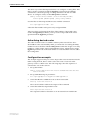
NEBS Compliant Models
Software Release 2.6.4 adds support for the following two new Network
Equipment Building Systems (NEBS) compliant Layer 3 switch models:
■
Rapier 24i (NEBS compliant)
■
AT-8724XL (NEBS compliant)
Contact your authorised distributor or reseller for ordering information.
Importing BGP routes into OSPF
With this enhancement you can import routes from BGP into OSPF. OSPF will
then redistribute these routes. This enhancement adds three parameters to the
set ospf command, and modifies the output of the show ospf command. The
new parameters are bgpimport, bgpfilter and bgplimit.
BGP can learn thousands of routes, so it’s important to consider the network
impact of importing these routes. Routing devices in the OSPF domain may
become overloaded if they store too many routes. You can prevent this by
limiting the number of routes that will be imported.
Do not enable the importing of BGP routes into OSPF unless you are sure about
the consequences for the OSPF domain.
Enabling BGP route import
To enable importing BGP routes into OSPF, use the command:
set ospf bgpimport=on
Limiting the number of routes
There are two ways to limit the number of BGP routes imported into OSPF.
One way is to specify a maximum number of routes with the command:
set ospf bgplimit=1...300
When the limit is reached, the importing of routes will stop until existing
routes are removed. Because they are BGP routes, actions of BGP control when
the routes disappear.
Software Release 2.6.4
C613-10404-00 REV A
Software Release 2.6.4
7
The other way to limit the imported routes is to configure a routing filter. This
filter is used in conjunction with the bgpfilter parameter in the set ospf
command to control the passing of routing information in and out of the
device. To configure a filter, use the add ip filter command:
add ip filter=filter-number {action=include|exclude}
source=ipadd [smask=ipadd] [entry=entry-number]
Use this filter to limit imported BGP routes with the command:
set ospf bgpfilter=300...399
where the filter number is the previously configured filter.
Take care when configuring the IP filter. If the number of imported routes
reaches the bgplimit parameter, you may not have imported all the routes
specified with the bgpfilter parameter.
Advertising desired routes
The order in which routes are added is arbitrary. This means that to have
desired BGP routes advertised by OSPF, you must take care setting the entry
number for the route filter with the add ip route command. Assign a low entry
number to a filter used to import preferred BGP routes. Alternatively, set the
bgplimit parameter above the total number of routes that BGP will ever add to
the routing table.
Configuration example
This example supposes that you want to import the route 192.168.72.0 into the
OSPF routing domain, but no other routes. This route is received on the
gateway router as a BGP route. The following steps show the sequence of
commands to use in this scenario.
1.
Set up the IP filter:
add ip filter=300 source=192.168.72.0 smask=255.255.255.255
action=include
2.
Set up OSPF BGP import parameters:
set ospf bgpimport=on bgpfilter=300 bgplimit=1
3.
Check that BGP has added the route to the IP route table:
show ip route=192.168.72.0
The route should be visible in the output of the command.
4.
Check that OSPF has imported the route:
show ospf lsa=192.168.72.0
The output should show that there is an AS external LSA with this ID.
Software Release 2.6.4
C613-10404-00 REV A
8
Release Note
SNMPv3
SNMPv3 provides enhanced security management features whilst maintaining
compatibility with earlier versions SNMPv1 and SNMPv2. The basic additional
features of version 3 are:
■
Message Authentication:
■
Hashing and time stamping is employed to ensure that messages are
received from valid sources.
■
Message Confidentiality
■
Encryption can be applied to messages to ensure content privacy.
■
Compatibility with previous versions SNMPv1 and SNMPv2
For more information, see the SNMP chapter in the Software Reference.
Stacking
Stacking affords the following advantages when managing a group of
switches:
■
Because stack members are connected by open standard Ethernet or uplink
switch ports, the switches can be at the same physical location or across
geographical areas.
■
Management interfaces are conserved because each stack is managed from
a single IP address or terminal connection.
■
Because a stack has one configuration file that is simple to maintain for all
member switches, it efficiently manages individual switches. Stacks are
easy to reconfigure in tune with changing network needs.
■
Stacks offer an alternative to managing a group of switches by using a CLI
or GUI on each switch, which is often tedious and time-consuming.
What is Stacking?
Stacking is a way to synchronise information across multiple switches and
manage them as one logical device. Stacking uses a proprietary protocol to
manage a group of separate switches as one.
When several switches perform similar functions, you can manage them as
one. For ease and simplicity, a stack can be managed from any stack member.
Topologies
A stack consists of a maximum of nine switches connected by switch ports in
the same Stacking VLAN. Stack members must be on the same LAN; however,
they can be in different physical locations. No extra hardware is required
because stack members use open standards interfaces. This allows flexible
topologies; typical ones are ring and star.
Software Release 2.6.4
C613-10404-00 REV A
Software Release 2.6.4
9
How Stacking Works
The Stacking feature centralises management by distributing and maintaining
system-wide information about stack members. It also:
■
Synchronises and propagates information about individual stack members
■
Propagates CLI and GUI commands
■
Manages responses and acknowledgements
■
Synchronises the stack configuration file
Switches have individual host IDs, which you set, so that they know which
device they are in the stack. Stacks have unique stack IDs, which you also set,
so that switches know to which stack they belong. Stack IDs are essential when
you have multiple stacks.
Stacked switches communicate with each other over a Stacking interface,
which is a user-defined virtual interface such as a VLAN. Ports in the Stacking
VLAN should be added as tagged VLAN ports to data VLANs. This ensures
that the Stacking VLAN carries user data.
For more information, see the Stacking chapter in the Software Reference.
ICMP Router Discovery Advertisements
This release supports all of RFC 1256, ICMP Router Discovery Messages, 1991 as
it applies to routers. If this feature is configured, the switch sends router
advertisements periodically and in response to router solicitations. It does not
support the Host Specification section of this RFC.
Before an IP host can send an IP packet, it has to know the IP address of a
neighbouring router that can forward it to its destination. ICMP Router
Discovery messages allow routers to automatically advertise themselves to
hosts. Other methods either require someone to manually keep these addresses
up to date, or require DHCP to send the router address, or require the hosts to
be able to eavesdrop on whatever routing protocol messages are being used on
the LAN.
Router Discovery Process
For a summary of the processes that occur when Router Discovery
advertisements are enabled for interfaces on the switch see Table 3 on page 9
Table 3: Router Discovery Process
When ...
Then ...
Router Discovery advertising starts on a
the switch multicasts a router advertisement
switch interface because:
and continues to multicast them periodically
- the switch starts up, or
until router advertising is disabled.
- advertisements are enabled on the switch
or on an interface
a host starts up
Software Release 2.6.4
C613-10404-00 REV A
the host may send a router solicitation
message.
10
Release Note
Table 3: Router Discovery Process (Continued)
When ...
Then ...
the switch receives a router solicitation
the switch multicasts an early router
advertisement on the multicast interface on
which it received the router solicitation.
a host receives a router advertisement
the host stores the IP address and preference
level for the advertisement lifetime.
the lifetime of all existing router
advertisements on a host expires
the host sends a router solicitation.
the host waits for the next unsolicited router
a host does not receive a router
advertisement after sending a small number advertisement
of router solicitations
a host needs a default router address
the host uses the IP address of the router or
L3 switch with the highest preference level.
Router Discovery advertising is deleted from
the physical interface (delete ip advertise
command), or the logical interface has
advertise set to no (set ip interface
command)
the switch multicasts a router advertisement
with the IP address(es) that stopped
advertising, and a lifetime of zero (0). It
continues to periodically multicast router
advertisements for other interfaces.
the switch receives a router advertisement
from another router
the switch does nothing but silently discards
the message.
Router Advertisement Messages
A router advertisement is an ICMP (type 10) message containing:
■
In the destination address field of the IP header, the interface's configured
advertisement address, either 224.0.0.1 (ALL) or 255.255.255.255
(LIMITED).
■
In the lifetime field, the interface's configured advertisement lifetime.
■
In the Router Address and Preference Level fields, the addresses and
preference levels of all the logical interfaces that are set to advertise.
Router Solicitation Messages
A router solicitation is an ICMP (type 10) message containing:
■
Source Address: an IP address belonging to the interface from which the
message is sent
■
Destination Address: the configured Solicitation Address, and
■
Time-to-Live: 1 if the Destination Address is an IP multicast address; at
least 1 otherwise.
Router Advertisement Interval
The router advertisement interval is the time between router advertisements.
For the first few advertisements sent from an interface (up to 3), the switch
sends the router advertisements at intervals of at most 16 seconds. After these
initial transmissions, it sends router advertisements at random intervals
between the minimum and maximum intervals that the user configures, to
reduce the probability of synchronization with the advertisements from other
routers on the same link. By default the minimum is 450 seconds (7.5 minutes),
and the maximum is 600 seconds (10 minutes).
Software Release 2.6.4
C613-10404-00 REV A
Software Release 2.6.4
11
Preference Level
The preference level is the preference of the advertised address as a default
router address relative to other router addresses on the same subnet. By
default, all routers and layer 3 switches have the same preference level, zero
(0). While it is entered as a decimal in the range -2147483648..2147483647, it
is encoded in router advertisements as a twos-complement hex integer in the
range 0x8000000 to 0x7fffffff. A higher preferencelevel is preferred over a
lower value.
Lifetime
The lifetime of a router advertisement is how long the information in the
advertisement is valid. By default, the lifetime of all advertisements is 1800
seconds (30 minutes).
Configuration Procedure
By default, the switch does not send router advertisements.
To configure the router to send router advertisements:
1.
Set the physical interface to advertise.
For each physical interface that is to send advertisements, add the
interface. In most cases the default advertising parameters will work well,
but you can change them if required. By default, the switch sends router
advertisements every 7.5 to 10 minutes, with a lifetime of 30 minutes.
These settings are likely to work well in most situations, and will not cause
a large amount of extra traffic, even if there are several routers on the LAN.
If you change these settings, keep these proportions:
lifetime=3 x maxadvertisementinterval
minadvertisementinterval=0.75 x maxadvertisementinterval
To change these settings, use one of the commands:
add ip advertise interface=interface
[advertisementaddress={all|limited}]
[maxadvertisementinterval=4..1800]
[minadvertisementinterval=3..maxadvertisementinterval]
[lifetime=maxadvertisementinterval..9000]
set ip advertise interface=interface
[advertisementaddress={all|limited}]
[maxadvertisementinterval=4..1800]
[minadvertisementinterval=3..maxadvertisementinterval]
[lifetime=maxadvertisementinterval..9000]
2.
Stop advertising on other logical interfaces.
By default, logical interfaces are set to advertise if their physical interface is
set to advertise. If the physical interface has more than one logical interface
(IP multihoming), and you only want some of them to advertise, set the
other logical interfaces not to advertise, using one of the commands:
add ip interface=interface ipaddress={ipadd|dhcp}
advertise=no [other-parameters...]
set ip interface=interface advertise=no
[other-parameters...]
Software Release 2.6.4
C613-10404-00 REV A
12
Release Note
3.
Set preference levels.
By default, every logical interface has the same preference for becoming a
default router (mid range, 0). To give a logical interface a higher preference,
increase the preferencelevel. To give it a lower preference, decrease this
value. If it should never be used as a default router, set it to notdefault.
add ip interface=interface ipaddress={ipadd|dhcp}
preferencelevel={-2147483648..2147483647|notdefault}
[other-parameters...]
set ip interface=interface
[preferencelevel={-2147483648..2147483647|notdefault}]
[other-parameters...]
4.
Enable advertising.
Enable router advertisements on all configured advertising interfaces,
using the command:
enable ip advertise
5.
Check advertise settings.
To check the router advertisement settings, use the command:
show ip advertise
For full descriptions of these commands, see the Internet Protocol (IP) chapter of
the Software Reference.
Support for Long File Names (DOS 28.3)
File names of up to twenty eight characters long and extensions of three
characters (DOS 28.3 format) are now supported.
All software releases support short filenames (DOS 8.3 format). Software
release 2.5.1 and later support long file names in either DOS 16.3 or DOS 28.3
format. The table below summarises which software releases support different
DOS filename formats.
Table 4: The DOS filename formats supported by different software releases
Software release
Dos 8.3 format
DOS 16.3 format
DOS 28.3 format
2.4.x and earlier
Yes
No
No
2.5.1 and later
Yes
Yes
No
2.6.4 and later
Yes
Yes
Yes
Upgrading to new software releases
When upgrading to software release 2.6.4 from any previous software release
file names retain their DOS naming format. DOS 8.3 format filenames remain
in DOS 8.3 format and DOS 16.3 format filenames remain in DOS 16.3 format.
Software Release 2.6.4
C613-10404-00 REV A
Software Release 2.6.4
13
Regressing to previous software releases
If software release 2.6.4 is installed on the switch and then a previous software
release that supports only DOS 8.3 format is installed (see Table 4), long file
names that were in DOS 28.3 format are truncated to DOS 8.3 format. When
software release 2.6.4 or later is reinstalled, these truncated file names are
restored to their DOS 28.3 format and no information is lost. Support for long
file names in only DOS 8.3 format is a feature of software releases prior to
software release 2.5.1.
If software release 2.6.4 is installed on the switch and then a previous software
release that supports DOS 16.3 format is installed (see Table 4), long file names
in DOS 28.3 format are permanently truncated to DOS 8.3 format. For example,
the file AB12345678.SCP is permanently renamed AB123~01.SCP. Any long file
names that were in DOS 28.3 format remain truncated in DOS 8.3 format when
software release 2.6.4 is reinstalled. Support for long file names in DOS 16.3
format is a feature of software release 2.5.1 up to software release 2.6.4.
For more information, see the Operations chapter of the Software Reference.
Testing Asynchronous and Switch Ports
For the enable test interface and disable test interface commands, the
interface parameter has been expanded. As well as the existing testable
interfaces, you can now test the following interfaces on all products with
switch ports:
■
asyn port n, using interface=asynn (for example, interface=asyn0)
■
switch port n, using interface=portn (for example, interface=port8)
This functionality is already available on AR400 series routers.
For more information, see the Test Facility chapter of the Software Reference.
Interrupting Text Flow with the CLI
A new function has been added for users of the Command Line Interface (CLI)
to let them interrupt (or “break”) text paging or continuously streaming text.
The key combination is Ctrl-Q.
This capability will be useful with stand alone commands such as show
commands that display many output screens. The text is buffered and
undisplayed text is deleted. The command prompt is then restored.
The paging prompt will continue giving users the option to display the next
line of text output or next page, print text continuously with no further
prompts, or abort text output.
This functionality will not work on commands that produce output of
indeterminate length, such as enable and disable commands where output
starts with enable and stops with disable.
For more information, see the Operations chapter of the Software Reference.
Software Release 2.6.4
C613-10404-00 REV A
14
Release Note
Disable 10/100 Ports at the Hardware
Level
When disabling a port or group of ports on the switch, you can now specify
that 10/100 Ethernet ports are disabled at the hardware level, using the
command:
disable switch port={port-list|all} [link={enable|disable}]
[other-parameters...]
The link parameter specifies whether 10/100 Ethernet ports are either enabled
or disabled at the hardware level. If disable is specified, this is the equivalent
of disconnecting the cable. If the link parameter is not specified, the link
remains physically enabled. The default is enable.
If a port has been disabled at the hardware level, when it is reset it is enabled at
the hardware level and autonegotiation of speed and duplex mode is activated.
For more information, see the Switching chapter of the Software Reference.
Specifying the Mode of Operation When
IGMP Snooping is Enabled
You can now specify the mode of operation when IGMP Snooping is enabled
with the command:
set igmpsnooping routermode=[all|default|ip|multicastrouter|
none]
If all is specified, all reserved multicast addresses (i.e. 224.0.0.1 to 224.0.0.255)
are treated as router multicast addresses.
If default is specified, the following addresses are treated as router multicast
addresses:
•
IGMP Query, 224.0.0.1
•
All routers on this subnet, 224.0.0.2
•
DVMRP Routers, 224.0.0.4
•
OSPFIGP all routers, 224.0.0.5
•
OSPFIGP designated routers, 224.0.0.6
•
RIP2 routers, 224.0.0.9
•
All PIM routers, 224.0.0.13
•
All CBT routers, 224.0.0.15
If ip is specified, you specify addresses treated as router multicast addresses
using the add igmpsnooping routeraddress and the delete igmpsnooping
routeraddress commands. When in this mode, your switch retains previous
addresses that have already been specified.
If multicastrouter is specified, the following addresses are treated as router
multicast addresses:
•
DVMRP Routers, 224.0.0.4
•
All PIM routers, 224.0.0.13
Software Release 2.6.4
C613-10404-00 REV A
Software Release 2.6.4
15
If none is specified, the switch does not create router ports at all.
To add and delete reserved IP multicast addresses to and from the list of router
multicast addresses specified by the set igmpsnooping routermode command
when the ip parameter is selected, use the commands:
add igmpsnooping routeraddress
delete igmpsnooping routeraddress
The IP addresses specified must be from 224.0.0.1 to 224.0.0.255.
To display information about the current list of configured IP multicast router
addresses configured on your switch, use the command:
show igmpsnooping routeraddress
For more information about IGMP Snooping, see the IP Multicasting chapter of
the Software Reference.
IP Route Filter Changes to Protocol
Parameter
IP routing filters affect the interaction between routing protocols, such as RIP
and OSPF, and the IP route table. Route filters control which routes received by
routing protocols are added to the IP route table, and which routes in the route
table can be advertised by routing protocols.
IP routing filters can no longer be applied to static routes and interface routes.
The list of options accepted by the protocol parameter in the add ip route filter
and set ip route filter commands has been modified. The new syntax is:
add ip route filter[=filter-id] ip=ipadd mask=ipadd
action={include|exclude} [direction={receive|send|both}]
[interface=interface] [nexthop=ipadd] [policy=0..7]
[protocol={any|egp|ospf|rip}]
set ip route filter=filter-id [ip=ipadd] [mask=ipadd]
[action={include|exclude}] [direction={receive|send|
both}] [interface=interface] [nexthop=ipadd] [policy=0..7]
[protocol={any|egp|ospf|rip}]
For more information about static routes and interface routes, see the Internet
Protocol (IP) chapter of the Software Reference.
Software Release 2.6.4
C613-10404-00 REV A
16
Release Note
Remote Security Officer (RSO) Login
There are two section to this enhancement. The first section applies to switches
that support Remote Security Officer (RSO) and IPv4 only. The second section
applies to switches and routers that support RSO, IPv4, and IPv6.
Remote Security Officer Login and IPv4 Only
This section applies to the AT-8600, AT-8700XL, AT-8800, Rapier, and Rapier i
Series switches.
The Remote Security Officer (RSO) feature lets a remote user connect to a
switch via Telnet from an authorised IP address, and login using a name with
Security Officer privilege as if the user were at a terminal connected directly to
the switch. The RSO feature is configured by defining authorised IP addresses
using the ADD USER RSO and DELETE USER RSO commands. These
commands now accept ranges of IP addresses:
add user rso ip=ipadd [mask=ipadd]
add user rso ip=ipadd[-ipadd]
delete user rso ip=ipadd[-ipadd]
where ipadd is an IP address in dotted decimal notation. If a mask is not
specified, the default is 255.255.255.255.
Remote Security Officer Login, IPv4 and IPv6
This section only applies to the AT-8800, Rapier, and Rapier i Series switches.
IPv6 addresses are now also supported, enabling Remote Security Officers to
login over an IPv6 network:
add user rso ip=ipv6add[/prefix-length]
add user rso ip=ipv6add[-ipv6add]
delete user rso ip=ipv6add/prefix-length
delete user rso ip=ipv6add[-ipv6add]
where ipv6add is an IPv6 address. If a prefix length is not specified, the default
is 128.
For more information about Remote Security Officer, see the Operations chapter
of the Software Reference.
Software Release 2.6.4
C613-10404-00 REV A
Software Release 2.6.4
17
Enable IPV6 MLD Interface Command
This enhancement is available on AT-8800, Rapier, and Rapier i Series switches.
This command lets users enable the Multicast Listener Discovery (MLD)
protocol on an interface that already exists. For Release 2.6.4, the v1compatible
parameter for the command has been replaced with the queryversion
parameter. The new syntax is:
enable ipv6 mld interface=interface [queryversion={1|2}]
where interface is a valid interface
Queryversion specifies the version of MLD Query to us on the interface. It is a
more accurate way to specify interoperability between MLDv2 and MLDv1.
The default is 2.
To avoid unnecessary error messages, we recommend that users replace
v1compatible with queryversion along with their related values in scripts
currently being used. For more information about Multicast Listener
Discovery, see the IPv6 Multicasting chapter of the Software Reference.
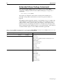
Text Message at Login (Welcome banner)
Before users get the prompt that lets them log in, contents from a file named
login.txt is displayed if it exists in flash memory. The login.txt file lets
various kinds of messages be sent to users. The following diagram is an
example of output from the login.txt file for the AT-8700, AT-8800, Rapier,
and Rapier i series switches.
INFO:
INFO:
PASS:
INFO:
…………
…………
INFO:
Self tests beginning.
RAM test beginning.
RAM test, 65536k bytes found.
BBR tests beginning.
Switch startup complete
Warning: This equipment is for authorised persons only. If you
do not have proper clearance, please logout now.
Login:
The following diagram is an example of output from the login.txt file for the
AT-8600 series switch.
Software Release 2.6.4
C613-10404-00 REV A
18
Release Note
INFO:
INFO:
PASS:
…………
…………
INFO:
Self tests beginning.
RAM test beginning.
RAM test, 65536k bytes found.
Switch startup complete
Warning: This equipment is for authorised persons only. If you
do not have proper clearance, please logout now.
Login:
Users with Manager privileges or higher create the file named login.txt by
using the edit command or by loading an existing text file. The contents of the
file must be in printable ASCII characters but with no control characters. When
no login.txt file exists, the login prompt is displayed without a message.
For more information to help create a login.txt file, see the edit command and
the load command in the Software Reference.
After someone with User privileges successfully logs in, the switch activates an
auto-executing file, autoexec.scp, if one is in flash memory. Users with
Manager privileges or higher also create these script files. For more
information about scripts, see the Scripting chapter of the Software Reference.
Private VLANs
Private VLANs are available on AT-8800 and Rapier i Series switches.
A private VLAN contains switch ports that are isolated from other ports in the
VLAN, but can access another network through an uplink port or uplink trunk
group. These ports are called private ports. Private ports may be stand alone or
be combined into groups. Stand alone private ports can only communicate
with the uplink port, not with other ports in the VLAN. Private ports that are in
a group can communicate with other ports in the group and with the uplink
port, but cannot communicate with the other private ports in the VLAN.
The switch forwards traffic between private ports and the uplink port, and
between private ports within a group, according to its normal forwarding
rules. The only difference is that forwarding to other private ports is blocked
unless the ports are in the same group. Note that all traffic between private
ports is blocked, not only Layer 2 traffic.
A typical application is a hotel installation where each room has a port that can
access the Internet. In this situation it is undesirable to allow communication
between rooms. Another application is to simplify IP address assignment.
Ports can be isolated from each other while belonging to the same subnet.
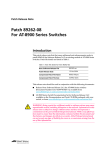
Figure 2 on page 19 shows an example of a network using private VLANs. In
this scenario, two service providers are each providing multiple services
through multiple VLANs over separate uplinks. Customers are subscribed to
services from one or both service providers. Each customer’s ports are isolated
from other customers, but communicate with the ISP or ISPs through the
Software Release 2.6.4
C613-10404-00 REV A
Software Release 2.6.4
19
appropriate uplink port. A single customer may use multiple ports, connected
to individual PCs or trunked together to increase bandwidth. If a customer
uses multiple ports, these ports are able to communicate with each other.
On Rapier i and AT-8800 Series switches, private VLANs obsolete protected VLANs
and the protected parameter of the create vlan command. If you run a configuration
that uses the protected parameter, the VLAN will be converted to a private VLAN.
Figure 2: Example network configuration using private VLANs
ISP 1
ISP 2
VLANs 2 and 3
VLANs 11 and 12
Uplink
(trunk group)
Uplink
17
18
19
20
21
22
23
24
1
2
3
4
5
6
7
8
private
port
private
port
private group
(may be a
trunk group)
Customer 1
VLAN 12
ISP 2
25
Customer 3
Customer 2
VLANs 2 and 3
ISP 1
VLANs 2, 3 and 11
ISPs 1 and 2
private-vlan
Membership Rules for Private VLANs
Each private VLAN:
■
Must contain one uplink port or uplink trunk group
■
May contain multiple private ports
■
Cannot contain any non-private ports
■
Cannot be the default VLAN (vlan1)
Each private port:
■
Can be a member of multiple private VLANs
■
Cannot be a private port in some VLANs and a non-private port in other
VLANs
■
Cannot be an uplink port in another VLAN
Each uplink port:
Software Release 2.6.4
C613-10404-00 REV A
■
Can be a member of multiple private VLANs
■
Cannot be a member of both private and non-private VLANs
20
Release Note
Each private or uplink port:
■
May be tagged or untagged, but can only be an untagged member of one
port-based VLAN
■
May be trunked with other ports of the same type
Private VLANs on Rapier 48i Switches
The ports on Rapier 48i switches are divided into two instances:
■
ports 1-24 plus uplink port 49
■
ports 25-48 plus uplink port 50
Private VLANs on a Rapier 48i switch can only consist of ports from one
instance. Both the private ports and the uplink port must be in the same
instance.
Configuring Private VLANs
To create a private VLAN and add ports to it:
1.
Create the VLAN
To create a VLAN and specify that it is private, use the command:
CREATE VLAN=vlan-name VID=2..4094 PRIVATE
2.
Add the uplink port or trunk group
To add the uplink to a private VLAN, use one of the commands:
ADD VLAN={vlan-name|1..4094} PORT=port-list
[FRAME={UNTAGGED|TAGGED}] UPLINK
where portlist is either a single port number for a single uplink port, or a
list of port numbers for a trunk group. If you are adding a trunk group to
the VLAN as an uplink, the ports must already be trunked together, and
you must specify all the ports.
3.
Add the private ports
To add a private port or ports to a private VLAN, use one of the
commands:
ADD VLAN={vlan-name|1..4094} PORT={port-list|ALL}
[FRAME={UNTAGGED|TAGGED}] [GROUP]
The GROUP parameter specifies that the listed ports may communicate
with each other, but not with any other private ports in the VLAN.
To delete ports from a private VLAN:
To delete private ports from a private VLAN, use one of the commands:
DELETE VLAN={vlan-name|1..4094} PORT=port-list
DELETE VLAN={vlan-name|1..4094} PORT=ALL
A private VLAN cannot contain any private ports when an uplink is
deleted from the VLAN, because a private VLAN must always have an
uplink. To delete the uplink port or ports and any private ports from a
private VLAN, use the PORT=ALL option in the above command.
If the port is a member of a private group, you must delete all ports in the
group at once. This stops groups from having different member ports in
different VLANs.
Software Release 2.6.4
C613-10404-00 REV A
Software Release 2.6.4
21
Modified Commands
The create vlan and add vlan port commands have been modified as described
below.
create vlan=vlan-name vid=2..4094 [private]
The private parameter specifies that the VLAN is a private VLAN. A private
VLAN contains ports or groups of ports that are isolated from the other ports
in the VLAN.
add vlan={vlan-name|1..4094} port={port-list|all}
[frame={tagged|untagged}] [uplink] [group]
The group parameter specifies that the listed ports may communicate with
each other, but not with any other private ports in the VLAN, and is only valid
for private VLANs. You can add a group of ports to multiple private VLANs,
as long as the group contains identical ports in each VLAN.
The uplink parameter specifies that the ports are to be added to the VLAN as
uplink ports, and is only valid for private VLANs. If more than one port is
specified then they must be a trunked group. Each private VLAN can only
have one uplink. The port must not be a member of any non-private VLAN
except the default VLAN. The ports can only be in another private VLAN if
they are the uplink for that VLAN.
If the VLAN is a private VLAN and you do not specify the uplink or group
parameter, then the ports will be added as individual private ports. Private
ports cannot be added to a private VLAN until the VLAN has an uplink port or
uplink trunk group added to it. The port must not be in any non-private
VLANs.
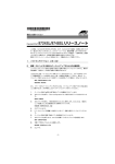
Output of the show vlan command has been modified to show whether the
VLAN is private or not, and the ports in private VLANs. See Figure 3 on
page 22.
Software Release 2.6.4
C613-10404-00 REV A
22
Release Note
Figure 3: Example output from the SHOW VLAN command.
VLAN Information
--------------------------------------------------------------------------Name ............... default
Identifier ......... 1
Status ............. static
Private VLAN ....... No
Untagged ports ..... 1,3-23
Tagged ports ....... None
Spanning Tree ...... default
Trunk ports ........ None
Mirror port ........ None
Attachments:
Module
Protocol
Format
Discrim
MAC address
------------------------------------------------------------------GARP
Spanning tree
802.2
42
IP
IP
Ethernet 0800
IP
ARP
Ethernet 0806
------------------------------------------------------------------Name ............... vlan2
Identifier ......... 2
Status ............. dynamic
Private VLAN ....... Yes
Untagged ports ..... 2,24
Tagged ports ....... None
Spanning Tree ...... default
Trunk ports ........ None
Mirror port ........ None
Attachments:
Module
Protocol
Format
Discrim
MAC address
------------------------------------------------------------------GARP
Spanning tree
802.2
42
------------------------------------------------------------------Private Uplink:
Uplink ports ...... 21-24
Private Groups:
Group ports ...... 3-5
Group ports ...... 6-9
--------------------------------------------------------------------
Configuration Example
To create vlan2 with two groups of private ports (3-5 and 6-9) connected to an
uplink trunk group (ports 21-24):
1.
Create vlan2, making it private.
create vlan=vlan2 vid=2 private
2.
Add the uplink trunk group to the VLAN. The ports must already be
trunked together.
add vlan=vlan2 port=21-24 uplink
3.
Define the groups and add their ports to vlan2.
add vlan=vlan2 port=3-5 group
add vlan=vlan2 port=6-9 group
Software Release 2.6.4
C613-10404-00 REV A
Software Release 2.6.4
23
Probing IP Addresses
When creating a DHCP range, you can now specify how the DHCP server
checks whether an IP address is being used by other hosts by specifying the
new probe parameter, with the command:
create dhcp range=name ip=ipadd number=number policy=name
[gateway=ipadd] [probe={arp|icmp}]
The probe parameter specifies how the DHCP server checks whether an IP
address is being used by other hosts. If arp is specified, the server sends ARP
requests to determine if an address is in use. If icmp is specified, the server
sends ICMP Echo Requests (pings). The default is icmp.
To modify the server’s method for probing IP addresses, use the new
command:
set dhcp range=name probe={arp|icmp}
Note that arp cannot be specified if the range includes a gateway (by specifying
the gateway parameter when it was created), or if the network uses Proxy ARP.
Note that arp cannot be specified if the range includes a gateway (by specifying the
gateway parameter when it was created), or if the network uses Proxy ARP.
For more information, see the Dynamic Host Configuration Protocol (DHCP)
chapter of the Software Reference.
Software Release 2.6.4
C613-10404-00 REV A
24
Release Note
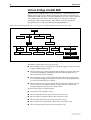
Virtual Bridge (VLAN) MIB
Support has been added for RFC 2674, “Definitions of Managed Objects for
Bridges with Traffic Classes, Multicast Filtering and Virtual LAN Extensions”
which defines MIB objects for managing IEEE 802.1Q VLANs. Objects defined
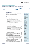
in this MIB reside in the mib(1) sub-tree (Figure 4 on page 24), under the
dot1dBridge sub-tree defined in RFC 1493, and have the object identifier
qBridgeMIBObjects ({ mib-2 dot1dBridge(17) qBridgeMIB(7) 1 }).
Figure 4: The Virtual Bridge (VLAN) sub-tree of the Internet-standard Management Information Base (MIB)
internet (1)
directory (1)
mgmt (2)
experimental (3)
mib (1)
cmot (9)
egp (8)
enterprises (1)
snmp (11)
transmission (10)
private (4)
appletalk (13)
ifExtensions (12)
bgp (15)
ospf (14)
dot1dBridge (17)
qBridgeMIB (7)
rmon (16)
qBridgeMIBObjects (1)
MIB12
The MIB is organised into four logical groups:
■
The dot1qBase Group contains general objects that apply to any device that
supports IEEE 802.1Q VLANs.
■
The dot1qTp Group contains objects that describe the operation and status
of transparent bridging, including the dynamic filtering databases for
unicast and multicast forwarding.
■
The dot1qStatic Group contains objects that describe static configurations
for transparent bridging, including static entries in the filtering databases
for unicast and multicast forwarding.
■
The dot1qVlan Group contains objects that describe the configuration and
status of VLANs, including statically configured VLANs and VLANs
configured dynamically by protocols like GVRP.
The following objects are implemented:
■
All objects in the dot1qBase Group.
■
The dot1qVlanNumDeletes object in the dot1qVlan Group.
■
The dot1qVlanCurrentTable object in the dot1qVlan Group.
■
The dot1qVlanStaticTable object in the dot1qVlan Group.
■
The dot1qNextFreeLocalVlanIndex object in the dot1qVlan Group.
■
The dot1qPortVlanTable object in the dot1qVlan Group.
Software Release 2.6.4
C613-10404-00 REV A
Software Release 2.6.4
25
Valid Values for IPv6 Router
Advertisement AdvRetransTimer
This enhancement is available on AT-8800, Rapier, and Rapier i Series switches.
The value you enter for the AdvRetrans timer is now rounded up to the nearest
100 milliseconds (for example, 301 becomes 400). The AdvRetrans timer is the
interval between repeats of each Router Advertisement message sent by the
switch, and is specified by using the retrans parameter in the command:
set ipv6 nd interface=interface retrans=0..4294967295
[other-parameters]
The default is 0, which indicates that this timer is not specified.
For more information, see the Internet Protocol Version 6 (IPv6) chapter of the
Software Reference.
Valid Characters for File Names - Show
File and Delete File Commands
For the show file and delete file commands only, the characters * > [ ] | : can
now be specified in the filename.
Files are uniquely identified by a file name in the format:
[device:]filename.ext
■
filename is a descriptive name for the file, and may be one to twenty eight
characters long. Invalid characters are “ \ ; ? / , <. Valid characters are:
•
uppercase and lowercase letters
•
digits (0–9)
•
the characters ~ ’ ! @ # $ % ^ & ( ) _ - { } * > [ ] | :
Wildcard characters * may appear anywhere in the filename. The wildcard
character matches any string.
Character ranges may be specified using the > character, for example a>z
matches any letter in the alphabet. The + character may be used to specify a list
of options, for example a*.scp+b*.scp would specify files that match a*.scp or
b*.scp.
Square brackets may be used, for example ppp*.[scp+cfg] matches scripts and
configuration files whose names start with “ppp”.
The vertical bar | character matches any single character. For example,
|||.scp matches script files with names three characters long (excluding
extension and device name).
If a colon is seen anywhere in the filename, the device parameter is ignored and
it is assumed that the filename includes the device name.
Software Release 2.6.4
C613-10404-00 REV A
26
Release Note
Extended Show Debug Command
The command show debug displays the output of a list of other show
commands. A full parameter has been added and displays a longer list of
commands:
show debug [stack|full]
The output also depends on the switch’s security mode and the user’s
privileges. The possible command list variations are given in Table 5 on
page 26.
The stack parameter limits the output to a stack dump, if one is available. The
output depends on whether the last fatal condition was a hardware reset or a
software reboot. After a software reboot, the output is a stack dump. After a
hardware reset, no stack dump information is available and a message to this
effect is displayed. If the stack parameter is not specified, both a stack dump if
available and the output of a list of show commands is generated.
Table 5: The list of show commands that are executed by the show debug command, when the full parameter is or is not
specified, under different combinations of security mode and privilege level
Full parameter specified? Security mode Privilege level
List of commands executed
No
normal
manager
No
secure
security officer
show system
show files
show install
show feature (AR400, AR700, AT-8800, Rapier and
Rapier i series)
show release
show config dynamic
show buffer scan
show cpu
show log
show exception
show ffile check
No
secure
manager
show system (without current configuration file)
show files
show install
show release
show buffer scan
show cpu
show log
show exception
show ffile check
Software Release 2.6.4
C613-10404-00 REV A
Software Release 2.6.4
27
Table 5: The list of show commands that are executed by the show debug command, when the full parameter is or is not
specified, under different combinations of security mode and privilege level (Continued)
Full parameter specified? Security mode Privilege level
List of commands executed
Yes
normal
manager
Yes
secure
security officer
show system
show files
show install
show feature (AR400, AR700, AT-8800, Rapier and
Rapier i series)
show release
show config dynamic
show interface
show ip interface
show ip arp
show ip route full
show ip count
show switch (AR400, AT-8700XL, AT-8800, Rapier and
Rapier i series)
show switch counter (AR400, AT-8700XL, AT-8800,
Rapier and Rapier i series)
show switch fdb (AR450, AT-8700XL, AT-8800, Rapier
and Rapier i series)
show startup
show flash
show switch port=all (AR400, AT-8700XL, AT-8800,
Rapier and Rapier i series)
show switch port=all counter (AR450, AT-8700XL,
AT-8800, Rapier and Rapier i series)
show buffer scan
show cpu
show log
show exception
show ffile check
Software Release 2.6.4
C613-10404-00 REV A
28
Release Note
Table 5: The list of show commands that are executed by the show debug command, when the full parameter is or is not
specified, under different combinations of security mode and privilege level (Continued)
Full parameter specified? Security mode Privilege level
List of commands executed
Yes
show system (without current configuration file)
show files
show install
show release
show interface
show ip interface
show ip arp
show ip route full
show ip count
show switch (AR400, AT-8700XL, AT-8800, Rapier and
Rapier i series)
secure
manager
show switch counter (AR400, AT-8700XL, AT-8800,
Rapier and Rapier i series)
show switch fdb (AR450, AT-8700XL, AT-8800, Rapier
and Rapier i series)
show startup
show flash
show switch port=all (AR400, AT-8700XL, AT-8800,
Rapier and Rapier i series)
show switch port=all counter (AR450, AT-8700XL,
AT-8800, Rapier and Rapier i series)
show buffer scan
show cpu
show log
show exception
show ffile check
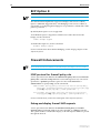
Extended Syslog Format
A new parameter, syslogformat, has been added to the create log output and
set log output commands:
create log output={temporary|permanent|output-id}
destination={email|memory|asyn|router|syslog}
[syslogformat=extended|normal] [other-parameters...]
set log output={temporary|permanent|output-id}
[syslogformat=extended|normal] [other-parameters...]
The permanent option for the output parameter is not available on AT-8600 Series
switches.
The syslogformat parameter specifies whether or not the log messages sent to
the syslog server contain the date, time and system name. If the parameter is
set to extended the date, time and system name are included. If the parameter
is set to normal the date, time and system name are not included in the syslog
message. This parameter is only valid if destination is syslog. The default is
normal.
Software Release 2.6.4
C613-10404-00 REV A
Software Release 2.6.4
29
Table 6: Examples of syslog messages with syslogformat=normal
<12>SSH:SSH/ACPT, SSH connection accepted - pwduser
<14>CH:CMD/USER, logoff
<12>USER:USER/LOFF, pwduser logoff on TTY17
Table 7: Examples of syslog messages with syslogformat= extended
23-Oct-2003 16:39:37 <12>SSH:SSH/ACPT, Src: AR450 ,SSH connection accepted - pwduser
23-Oct-2003 16:39:41 <14>CH:CMD/USER, Src: AR450 ,logoff
23-Oct-2003 16:39:41 <12>USER:USER/LOFF, Src: AR450 ,pwduser logoff on TTY17
To set the system name to a unique identifier, use the command set system
name.
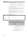
TACACS+ Authentication and Telnet
If your login to the switch is authenticated using TACACS+, you can only use
outbound telnet if your TACACS+ privilege level is also equal to or higher than
the minimum TACACS+ privilege level required for using telnet on the device.
By default, no TACACS+ users can telnet from the switch. To set a privilege
level, use the command:
set tacplus telnet={0..15|none}
A value of none is the default and disables telnet for all TACACS+
authenticated users. A value of 1 indicates that all users can telnet. TACACS+
privilege levels of 1-6 correspond to User level privilege, privilege levels 7-14
are mapped to Manager, and privilege level 15 are mapped to Security Officer.
Therefore a value of 7-14 indicates that Manager privilege or better is required.
A value of 15 is equivalent to Security Officer privilege.
Note that a user can have a TACACS+ privilege level that is equivilent to User
or Manager but be unable to use telnet on the device if the TACACS+ privilege
level required for using telnet is higher than the privilege level they have been
assigned. For example, if the TACACS+ privilege level required for using telnet
is set to 10 and there are two users with Manager privileges, one with a
TACACS+ privilege level of 9 and one with a privilege level of 10, only the user
with a privilege level of 10 can use telnet on the device.
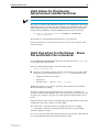
For example, to allow telnet for TACACS+ authenticated Security Officers, use
the command:
set tacplus telnet=15
To see the required privilege level, use the command:
show tacplus telnet
Figure 5: Example output from the show tacplus telnet command.
TACACS+ telnet privilege level: NONE
Software Release 2.6.4
C613-10404-00 REV A
30
Release Note
Table 8: Parameters displayed in the output of the show tacplus telnet command.
Parameter
Meaning
TACACS+ telnet privilege level The level of TACACS+ privilege required for using telnet on
the switch; a number in the range 0 to 15, or none. None
indicates that no TACACS+ authenticated user can use
telnet.
Adopting the VRRP IP Address
Benefits of VRRP IP Address Adoption
The VRRP master router can adopt the IP address of the virtual router (VR), and
respond to the following packets destined for the VR IP address, even if it does
not own this IP address on any of its interfaces:
■
ICMP echo requests (pings)
■
Telnet and SSH connection requests
■
HTTP and SSL GUI management requests
■
SNMP requests, and
■
DNS relay requests
VRRP IP Address Adoption allows continuous accessibility of the VR IP
address even as the VR master changes. Using this feature:
■
You can easily tell whether the VR is functioning, by pinging the single VR
IP address.
■
You can easily monitor the performance of the VR, regardless of which
participating router is acting as master.
■
DNS relay can continue functioning via the same IP address at all times.
Risks of VRRP IP Address Adoption
When VRRP IP Address Adoption is used, the master router accepts packets
destined for the virtual router, even though it may not own this IP address.
This does not conform to RFC 2338. Because the same IP address refers to
different devices at different times, there is a risk of confusion arising. This risk
can be reduced by a suitable network management policy.
Recommendations
Before using VR IP address adoption, consider the following guidelines to
avoid confusion:
■
Ensure that the VR has an IP address that is different from the interface IP
addresses of any of the individual routers in the VR.
■
Ensure that all routers in the virtual router use VRRP IP Address Adoption
(or that none do).
■
Use the VRRP IP address to monitor the VR master. Be aware that this does
not give information about one particular participating router, but about
the current VR master, whichever participating router is acting as the
master at the time.
Software Release 2.6.4
C613-10404-00 REV A
Software Release 2.6.4
31
■
When changing the configuration of the participating routers using Telnet,
GUI or SNMP, configure each device individually by pointing to their
individual IP addresses.
■
When changing the configuration of the participating routers, do not use
the VR IP address. Only one device, the VR master, is responding to this IP
address, and you may not know which device it is.
Configuration of VR IP Address Adoption
To configure VRRP IP Address Adoption, use the new parameter, adoptvrip,
that has been added to the create vrrp and set vrrp commands:
create vrrp=vr-identifier over=physical-interface
ipaddress=ipadd [adoptvrip={on|off}]
[other-parameters...]
set vrrp=vr-identifier [adoptvrip={on|off}]
[other-parameters]
The adoptvrip parameter specifies that when the switch is acting as the VRRP
master it should respond to requests directed at any IP address that it is
backing up, even if it does not own that address. If it does not own the address
the access requests that the switch will permit are limited to: ICMP echo
requests (pings), Telnet, SSH, HTTP and SSL GUI, SNMP and DNS relay. All
other types of access to the address will be ignored. The default is OFF.
If you set adoptvrip to on, give the VR an IP address that is different from the
interface IP addresses of any of the individual routers in the VR, and only use
the VR IP address to monitor the VR, not to configure any of its participating
routers. Otherwise you risk confusion when you monitor or configure
individual routers. See Synchronising Time Across Stacks on page 9 for more
about risks and recommendations.
Configure all the switches in a virtual router with the same values for the
VRRP virtual router identifier, IP address, adopt VR IP address mode,
advertisement interval, preempt mode, authentication type and password.
Inconsistent configuration will cause advertisement packets to be rejected and
the virtual router will not perform properly.
To display the value of the new parameter, use the show vrrp command.
Table 9: New parameter displayed in the output of the show vrrp command
Software Release 2.6.4
C613-10404-00 REV A
Parameter
Meaning
Adopt VR IP Address(es)
Whether or not the switch should respond to ICMP
echo, Telnet, GUI, SNMP and DNS relay service
requests targeted at the VR IP address(es) associated
with the virtual router, even if it does not own those
address(es).
32
Release Note
BCP Option 8
This enhancement is available on Rapier and Rapier i Series switches.
This enhancement implements support for Bridge Control Protocol (BCP)
Option 8 (IEEE 802 Tagged Frames). The Bridging Control Protocol (BCP) is
responsible for configuring the bridge protocol parameters on both ends of the
point-to-point link.
By default, BCP Option 8 is not supported.
To enable BCP Option 8 negotiation with the Peer at the other end of the
bridge, use the command:
enable bridge tagged
To disable BCP Option 8, use the command:
disable bridge tagged
For more information about Remote Bridging, see the Bridging chapter of the
Software Reference.
Firewall Enhancements
These enhancements are available on AT-8800, Rapier, and Rapier i Series switches.
ICMP protocol for firewall policy rule
A new option has been added to the add firewall policy rule and set firewall
policy rule commands. Icmp (Internet Control Message Protocol) can now be
specified as a protocol parameter option for rules with action=nat or
action=nonat. To specify icmp, use the commands:
add firewall policy=policy rule=rule-id action={allow|deny|
nat|nonat} interface=interface protocol={protocol|all|egp|
gre|icmp|ospf|sa|tcp|udp} [other-parameters...]
set firewall policy=name rule=rule-id [protocol={protocol|
all|egp|gre|icmp|ospf|sa|tcp|udp}] [other-parameters...]
For more information, see the Firewall chapter of the Software Reference.
Debug and display firewall ARP requests
A new option has been added to the disable firewall policy and enable
firewall policy commands. Arp can now be specified as a debug parameter.
This option enables or disables the display of all ARP requests that have passed
through the firewall.
Software Release 2.6.4
C613-10404-00 REV A
Software Release 2.6.4
33
To specify arp, use the commands:
[debug={all|arp|http|packet|
pkt|process|proxy|smtp}] [other-parameters...]
enable firewall policy=name
[debug={all|arp|http|packet|
pkt|process|proxy|smtp}] [other-parameters...]
disable firewall policy=name
A switch that is also acting as a NAT device will now respond to ARP requests
for any of its global IP addresses.
A new command, show firewall arp, displays information about IP addresses
specified in Firewall NAT configurations for which ARP responses from the
switch may be required. To display this information, use the command:
show firewall arp [policy=name]
The policy parameter specifies a firewall policy and displays IP addresses for
NAT configurations with that policy. If this parameter is not specified, IP
addresses are displayed for all policies.
An example output and the parameter descriptions for the show firewall arp
are shown below.
Figure 6: Example output from the show firewall arp command
IP
ARP Interfaces NAT Type
Int
Gbl Int
Rule
(range)
Policy
-------------------------------------------------------------------------------172.20.8.50
Public
Int based
eth0-0
eth1-0
Office
172.20.8.57
All Public
Rule
eth0-1
1
-172.20.8.62
LAN
--------------------------------------------------------------------------------
Table 10: Parameters in the output of the show firewall arp command
Parameter
Meaning
IP (range)
An IP address or range for which the switch may be required to
send ARP responses.
Policy
The name of the policy whose NAT configuration the IP address
(range) belongs to.
ARP Interfaces
Interfaces in the policy on which ARP requests are permitted:
Public
- ARP requests are permitted on the public interface
specified by the Gbl Int parameter
All Public - ARP requests are permitted on all of the policy's public
interfaces
Private
- ARP requests are permitted on the private interface
specified by the Int parameter
All Private - ARP requests are permitted on all of the policy's
private interfaces
An address in an ARP request must match the subnet of the
interface on which the ARP request is received.
Software Release 2.6.4
C613-10404-00 REV A
34
Release Note
Table 10: Parameters in the output of the show firewall arp command (Continued)
Parameter
Meaning
NAT Type
The type of NAT configuration associated with the IP address:
Int Based - The address (range) was specified by an interfacebased NAT configured with the add firewall policy
nat command
Rule
Int
- The address (range) was specified by a NAT rule
configured by the add firewall policy rule
command, where the ACTION parameter was
specified as NAT
The private interface associated with the NAT configuration. If the
NAT Type is Int based, this is the private interface specified by the
INTERFACE parameter in the add firewall policy nat command.
If the NAT Type is Rule, this is the interface to which the rule is
attached.
If this is a private interface, a dash indicates that the rule is
attached to a public interface (see the Gbl Int parameter).
Gbl Int
The public interface associated with the NAT configuration. If the
NAT Type is Int based, this is the public interface specified by the
GBLINTERFACE parameter in the add firewall policy nat
command.
If the NAT Type is Rule, this is the interface to which the rule is
attached.
if this is a public interface, a dash indicates that the rule is attached
to a private interface (see the Int parameter).
Rule
The number of the rule associated with this entry. When the NAT
Type is Int based, no value is displayed.
For more information, see the Firewall chapter of the Software Reference.
Software Release 2.6.4
C613-10404-00 REV A
Software Release 2.6.4
Software Release 2.6.4
C613-10404-00 REV A
35
36
Release Note
Software Release 2.6.4
C613-10404-00 REV A