1
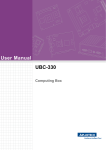
User Manual WISE-3310 Copyright The documentation and the software included with this product are copyrighted 2015 by Advantech Co., Ltd. All rights are reserved. Advantech Co., Ltd. reserves the right to make improvements in the products described in this manual at any time without notice. No part of this manual may be reproduced, copied, translated or transmitted in any form or by any means without the prior written permission of Advantech Co., Ltd. Information provided in this manual is intended to be accurate and reliable. However, Advantech Co., Ltd. assumes no responsibility for its use, nor for any infringements of the rights of third parties, which may result from its use. Acknowledgements Linear Dust is a trademark of Linear Technology Corporation. ARM is a trademark of ARM Corporation. All other product names or trademarks are properties of their respective owners. Packing List Before setting up the system, check that the items listed below are included and in good condition. If any item does not accord with the table, please contact your dealer immediately. Gateway – WISE-3310 (P/N: WISE-3310-D200L1E) Accessory – 2.4 GHz Antenna *2 (P/N: 1750007622-01) – Adapter *1 (P/N: 96PSA-A36W12R1) WISE-3310 User Manual Part No. Edition 1 Printed in Taiwan September 2015 ii Safety Instructions 1. 2. 3. Read these safety instructions carefully. Keep this User Manual for later reference. Disconnect this equipment from any AC outlet before cleaning. Use a damp cloth. Do not use liquid or spray detergents for cleaning. 4. For plug-in equipment, the power outlet socket must be located near the equipment and must be easily accessible. 5. Keep this equipment away from humidity. 6. Put this equipment on a reliable surface during installation. Dropping it or letting it fall may cause damage. 7. The openings on the enclosure are for air convection. Protect the equipment from overheating. DO NOT COVER THE OPENINGS. 8. Make sure the voltage of the power source is correct before connecting the equipment to the power outlet. 9. Position the power cord so that people cannot step on it. Do not place anything over the power cord. 10. All cautions and warnings on the equipment should be noted. 11. If the equipment is not used for a long time, disconnect it from the power source to avoid damage by transient overvoltage. 12. Never pour any liquid into an opening. This may cause fire or electrical shock. 13. Never open the equipment. For safety reasons, the equipment should be opened only by qualified service personnel. 14. If one of the following situations arises, get the equipment checked by service personnel: The power cord or plug is damaged. Liquid has penetrated into the equipment. The equipment has been exposed to moisture. The equipment does not work well, or you cannot get it to work according to the user's manual. The equipment has been dropped and damaged. The equipment has obvious signs of breakage. 15. DO NOT LEAVE THIS EQUIPMENT IN AN ENVIRONMENT WHERE THE STORAGE TEMPERATURE MAY GO BELOW -40° C (-40° F) OR ABOVE 85° C (185° F). THIS COULD DAMAGE THE EQUIPMENT. THE EQUIPMENT SHOULD BE IN A CONTROLLED ENVIRONMENT. 16. CAUTION: THERE IS DANGER OF EXPLOSION IF BATTERY IS INCORRECTLY REPLACED. REPLACE ONLY WITH THE SAME OR EQUIVALENT TYPE RECOMMENDED BY THE MANUFACTURER, DISCARD USED BATTERIES ACCORDING TO THE MANUFACTURER'S INSTRUCTIONS. The sound pressure level at the operator's position according to IEC 704-1:1982 is no more than 70 dB (A). DISCLAIMER: This set of instructions is given according to IEC 704-1. Advantech disclaims all responsibility for the accuracy of any statements contained herein. iii WISE-3310 User Manual WISE-3310 User Manual iv Contents Chapter 1 General Introduction ...........................1 1.1 1.2 1.4 1.5 Introduction ............................................................................................... 2 Product Features....................................................................................... 2 1.2.1 Key Features................................................................................. 2 1.2.2 Key Specification .......................................................................... 2 Mechanical Specification........................................................................... 3 1.3.1 Dimensions: .................................................................................. 3 Power Requirement .................................................................................. 3 Environment Specifications....................................................................... 3 2 Hardware Functionality .......................5 2.1 2.2 Introduction ............................................................................................... 6 WISE-3310 I/O Indication.......................................................................... 6 Figure 2.1 WISE-3310 front view................................................. 6 Figure 2.2 WISE-3310 Back view ................................................ 6 WISE-3310 Antenna Connectors .............................................................. 6 2.3.1 Spare Antenna Hole...................................................................... 6 2.3.2 Power Input Connector ................................................................. 7 2.3.3 Power Switch ................................................................................ 7 2.3.4 COM Connector ............................................................................ 7 Table 2.1: COM Connector Pin Assignment................................ 7 2.3.5 Reset Button ................................................................................. 8 2.3.6 Ethernet Connector (LAN) ............................................................ 8 Table 2.2: LAN Connector Pin Assignment ................................. 8 2.3.7 SD Connector ............................................................................... 9 Table 2.3: SD Connector Pin Assignment ................................... 9 WISE-3310 Hardware Installation ............................................................. 9 2.4.1 SD Card Installation ...................................................................... 9 Figure 2.3 WISE-3310 SD Card Installation ................................ 9 2.4.2 Mounting Assembly Method........................................................ 10 Figure 2.4 Flexible wall mounting .............................................. 10 Test Tools ............................................................................................... 10 2.5.1 SD Test ....................................................................................... 10 2.5.2 Mini PCIe (Wi-Fi) Test................................................................. 11 2.5.3 LAN Test ..................................................................................... 11 2.5.4 RS232 Test ................................................................................. 12 1.3 Chapter 2.3 2.4 2.5 Chapter 3 Building a WSN Network...................13 3.1 3.2 3.3 Default Setting......................................................................................... 14 Login ....................................................................................................... 14 Web Setting Functions ............................................................................ 15 3.3.1 Webmin....................................................................................... 15 3.3.2 System ........................................................................................ 15 Table 3.1: Bootup and Shutdown .............................................. 16 3.3.3 Networking .................................................................................. 18 Table 3.2: WISE WSN Setting................................................... 19 Table 3.3: WSN Network Statistic ............................................. 20 Table 3.4: WSN Network Statistic ............................................. 20 3.3.4 Hardware .................................................................................... 20 v WISE-3310 User Manual Chapter 4 Basic COM Port Settings.................. 23 4.1 Introduction ............................................................................................. 24 4.1.1 CLI Access.................................................................................. 24 4.1.2 Managing user and viewer Passwords ....................................... 25 4.1.3 Mote Commands ........................................................................ 25 Commands.............................................................................................. 25 4.2.1 Login ........................................................................................... 25 4.2.2 Logout......................................................................................... 26 4.2.3 Reset .......................................................................................... 26 4.2.4 Show Config & Show Curconfig.................................................. 27 4.2.5 Show Mote.................................................................................. 28 4.2.6 Show Stat ................................................................................... 29 4.2.7 Set Netid & Set Commonjoinkey ................................................ 30 4.2.8 exec exchNetId ........................................................................... 31 4.2.9 exec exchJoinKey....................................................................... 31 4.2.10 sm ............................................................................................... 32 4.2 WISE-3310 User Manual vi Chapter 1 1 General Introduction 1.1 Introduction Advantech Wireless IoT Gateway, WISE-3310, is powered by Freescale ARM® Cortex™-A9 i.MX6 Dual 1 GHz high performance processor. With high-reliability wireless mesh network solution and remote management, WISE-3310 creates a cost-effective open platform for easy integration and development in different M2M/IoT applications. Connect with Advantech Wireless IoT nodes, by Smartmesh IP protocol for applications in wireless sensor networks where seamless internet protocol (IP) is valued. Also, WISE-3310 supportS SUSIAccess for an IoT PaaS Solution; it allows users to easily remote control and manage their devices through WISE CLOUD. 1.2 Product Features 1.2.1 Key Features Freescale ARM® Cortex™-A9 i.MX6 Dual 1 GHz high performance processor Onboard DDR3 1 GB memory and 4 GB flash capability Linear Tech Dust WSN IP Smartmesh solution Complaint with IPv6, 6LowPAN Internet Protocol and IEEE802.15.4e standard Supports wallmount, VESA mount for flexible mounting methods 1.2.2 Key Specification Kernel: Linux V3.0.35 System Memory: Onboard 1GB DDR3 memory Flash: Onboard 4 GB e.MMC flash COM Port: 1 x RS232 Port (2 wires) LED: 2 LED for WSN network power status SD slot: 1 x SD Slot Power input: 12 V DC Power reset: 1 x reset button for system reboot WISE-3310 User Manual 2 Chapter 1 1.3 Mechanical Specification 1.3.1 Dimensions: 205 x 126 x 31 mm (L x W x H) with the metal plate 180 x114 x 31 mm without metal plate General Introduction 1.4 Power Requirement System Power: DC 12 V RTC Battery: 3 V/210 mAh 1.5 Environment Specifications Operating Temperature: 0 ~ 40° C (32 ~ 104° F) Relative Humidity: 95% @ 40° C (non-condensing) Storage Temperature: -20 ~ 60° C (-4 ~ 104° F) Vibration Loading During Operation: 1 Gms, IEC 60068-2-64, random, 5 ~ 500 Hz, 1 Oct/min, 1 hr/axis. EMC: CE, FCC Class B 3 WISE-3310 User Manual WISE-3310 User Manual 4 Chapter 2 Hardware Functionality 2 2.1 Introduction The following sections show the external connectors and pin assignments for applications. 2.2 WISE-3310 I/O Indication Figure 2.1 WISE-3310 front view Figure 2.2 WISE-3310 Back view 2.3 WISE-3310 Antenna Connectors 2.3.1 Spare Antenna Hole The WISE-3310 provides 2 spare antenna holes for standard SMA connectors. WISE-3310 User Manual 6 The WISE-3310 comes with a DC-jack header for 12V DC external power input. Hardware Functionality 2.3.3 Power Switch The WISE-3310 has a power switch on the front side. 2.3.4 COM Connector The WISE-3310 provides one D-sub 9-pin connector serial communication interface port. The port can support RS-232 mode communication. Table 2.1: COM Connector Pin Assignment Pin Description Pin Description 1 N/C 2 UART1_RXD 3 UART1_TXD 4 N/C 5 GND 6 N/C 7 N/C 8 N/C 9 N/C 7 Chapter 2 2.3.2 Power Input Connector WISE-3310 User Manual 2.3.5 Reset Button The WISE-3310 has a reset button on the front side. Press this button to activate the hardware reset function. 2.3.6 Ethernet Connector (LAN) The WISE-3310 provides one RJ45 LAN interface connector, it is fully compliant with IEEE 802.3u 10/100/1000 Base-T CSMA/CD standards. The Ethernet port provides standard RJ-45 connector with LED indicators on the front side to show Active/Link status. Table 2.2: LAN Connector Pin Assignment Pin Description 1 TX+(10/100),BI_DA+(GHz) 5 BI_DC-(GHz) 2 TX-(10/100),BI_DA-(GHz) 6 RX-(10/100),BI_DB-(GHz) 3 RX+(10/100),BI_DB+(GHz) 7 BI_DD+(GHz) 4 BI_DC+(GHz) 8 BI_DD-(GHz) WISE-3310 User Manual Pin 8 Description The WISE-3310 provides an SD slot. Users can insert an SD card easily. Hardware Functionality Table 2.3: SD Connector Pin Assignment Pin Description Pin 1 SD2_DATA3 2 SD2_CMD 3 GND 4 +V3.3 5 SD2_CLK 6 GND 7 SD2_DATA0 8 SD2_DATA1 Description 9 SD2_DATA2 10 SD2_CD# 11 GND 12 SD2_WP 2.4 WISE-3310 Hardware Installation 2.4.1 SD Card Installation 1. 2. Switch off the Power switch. Insert SD Card directly into the WISE-3310 SD slot, as Figure 2.3. Figure 2.3 WISE-3310 SD Card Installation 9 Chapter 2 2.3.7 SD Connector WISE-3310 User Manual 2.4.2 Mounting Assembly Method You can fix WISE-3310 to a wall by using wall mounting kit, as Figure 2.4. Figure 2.4 Flexible wall mounting 2.5 Test Tools All test tools must be verified on WISE-3310, please prepare required test fixtures before verifying each specified I/O. If you have any problems getting test fixtures, please contact Advantech for help. 2.5.1 SD Test 1. When booting from eMMC, you should see only the directories below: #ls /dev/mmcblk* /dev/mmcblk0 /dev/mmcblk0boot0 /dev/mmcblk0boot1 /dev/ mmcblk0p1 2. Insert SD card to SD card slot (SD1) and check your device again. You should be able to see more directories. /dev/mmcblk1 is the SD card storage. #ls /dev/mmcblk* /dev/mmcblk0 /dev/mmcblk0boot1 /dev/mmcblk1 /dev/mmcblk1p2 /dev/mmcblk0boot0 /dev/mmcblk0p1 /dev/mmcblk1p1 3. Create a file and copy to SD. #echo 123456789ABCDEF > test.txt #dd if=./test.txt of=/dev/mmcblk1 bs=1024 count=1 seek=25118 0+1 records in 0+1 records out 16 bytes (16 B) copied, 0.000109331 s, 146 kB/s WISE-3310 User Manual 10 Note! 2.5.2 Mini PCIe (Wi-Fi) Test The command used to test Wi-Fi module is as follows, the supported module P/N is EWM-W142H01E. #ifconfig wlan0 up #iwlist wlan0 scanning #wpa_passphrase “Wifi name” password > /tmp/wpa.conf #wpa_supplicant –Bdwext –iwlan0 –c/tmp/wpa.conf #dhclient wlan0 2.5.3 LAN Test WISE-3310 sets DHCP as default network protocol. #ifconfig eth0 Link encap:Ethernet HWaddr 00:04:9F:01:30:E0 inet addr:172.17.21.96 Bcast:172.17.21.255 Mask:255.255.254.0 UP BROADCAST RUNNING MULTICAST MTU:1500 Metric:1 RX packets:129 errors:0 dropped:18 overruns:0 frame:0 TX packets:2 errors:0 dropped:0 overruns:0 carrier:0 collisions:0 txqueuelen:1000 RX bytes:15016 (14.6 KiB) TX bytes:656 (656.0 B) lo Link encap:Local Loopback inet addr:127.0.0.1 Mask:255.0.0.0 UP LOOPBACK RUNNING MTU:16436 Metric:1 RX packets:0 errors:0 dropped:0 overruns:0 frame:0 TX packets:0 errors:0 dropped:0 overruns:0 carrier:0 collisions:0 txqueuelen:0 RX bytes:0 (0.0 B) TX bytes:0 (0.0 B) 11 WISE-3310 User Manual Hardware Functionality Please make sure that parameter “seek” is equal to 25118 as indicated in the above codes. If you create the file to a wrong sector, that may damage the system. Chapter 2 4. Check if the file was created successfully. #hexdump -C /dev/mmcblk1 -s 25720832 -s 32 01887800 31 32 33 34 35 36 37 38 39 41 42 43 44 45 46 0a |123456789ABCDEF.| 01887810 1d 4f e2 19 d3 05 8b df ab 4a 40 5a c5 23 3c f2 |................| If you would like to config IP manually, please use the command below: #ifconfig eth0 xxx.xxx.xxx.xxx up Here is a real case for your reference.The host’s (WISE-3310) IP is 172.17.21.97; the target (a desktop computer) IP is 172.17.20.192. #ifconfig eth0 172.17.21.97 up #ifconfig eth0 eth0 Link encap:Ethernet HWaddr 00:04:9F:01:30:E0 inet addr:172.17.21.97 Bcast:172.17.255.255 Mask:255.255.0.0 UP BROADCAST RUNNING MULTICAST MTU:1500 Metric:1 RX packets:2851 errors:0 dropped:271 overruns:0 frame:0 TX packets:30 errors:0 dropped:0 overruns:0 carrier:0 collisions:0 txqueuelen:1000 RX bytes:291407 (284.5 KiB) TX bytes:2000 (1.9 KiB) The target computer (Client) IP address is 172.17.20.192, so we can use the below command to see if we can get any response from the client. #ping 172.17.20.192 PING 172.17.20.192 (172.17.20.192): 56 data bytes 64 bytes from 172.17.20.192: seq=0 ttl=128 time=7.417 ms 64 bytes from 172.17.20.192: seq=1 ttl=128 time=0.203 ms 64 bytes from 172.17.20.192: seq=2 ttl=128 time=0.300 ms --- 172.17.20.192 ping statistics --3 packets transmitted, 3 packets received, 0% packet loss round-trip min/avg/max = 0.203/2.640/7.417 ms 2.5.4 RS232 Test RS232 port is debug console for WISE-3310. WISE-3310 User Manual 12 Chapter 3 Building a WSN Network 3 This chapter will show you how to configure WISE-3310 by using the web-based configuration interface. 3.1 Default Setting Please use your Ethernet port to connect to WISE-3310. IP Address 192.168.0.1 User Name/ Password admin/admin Network ID WSN1/ WSN2 2001/2002 Join Key JOINADVANTECHIOT 3.2 Login 1. Open a web browser (Chrome is suggested) and enter the IP Address. http://192.168.0.1 Note! 2. If you have changed the default LAN IP Address of this device, ensure you enter the correct IP Address. The default username and password are both admin. Once you have entered the correct username and password, click the Login button to open the webbase configuration page. WISE-3310 User Manual 14 If successful, you will be logged in and see the following page. The main functions of WISE-3310 web setting will be introduced in this section. 3.3.1 Webmin Under Webmin, you can change Username and Password on Webmin Users page. 3.3.2 System The System section contains the following items: Back to Factory Default, Bootup and Shutdown, Firmware Update and Running Process. 3.3.2.1 Back to Factory Default Click on Back to Advantech factory default, to revert the values of all web settings will be back to original setting. 15 WISE-3310 User Manual Building a WSN Network 3.3 Web Setting Functions Chapter 3 3. 3.3.2.2 Bootup and Shutdown In this page, all actions running in the system appearing in the table. Table 3.1: Bootup and Shutdown Start Start immediately Stop Stop immediately Restart Restart immediately Start On Boot Start when device on boot Disable On Boot Disable when device on boot Start Now and On Boot Start immediately and start when device on boot Disable Now and On Boot Disable immediately and disable when device on boot Reboot System Click on this button to immediately reboot the system. All currently logged in users will be disconnected and all services will be re-started. 3.3.2.3 Firmware Update Please download the most updated Firmware version from Advantech Website and upload the image into SD card. After plugging the SD card into SD card slot, Firmware update process can be started. Click browse icon to view image file in the SD card. WISE-3310 User Manual 16 Chapter 3 Double click “mmcb1p1” folder. Building a WSN Network Select the file with “emmc.img.gz”. Click update icon to start firmware update. The firmware update process may take around 5~10 minutes; please don’t turn off the power or press the reset button. After the process completes, please type the default IP address to return to login page. 17 WISE-3310 User Manual Please note, after firmware upgrade, the system will restore its default setting, the IP address will return to 192.168.0.1. Note! The device is unavailable during the upgrade process. Any connections to or through the device will be lost. 3.3.2.4 Running Process This page shows all running processes on your system, with child processes indented and displayed below their parent. For each process the PID, owner and command are displayed. Please click Help to get more information. 3.3.3 Networking The Networking section contains the following options: Network Configuration and WISE WSN Setting. 3.3.3.1 Network Configuration On this page, you can set Network Interface, Routing Gateways, Hostname and DNS Client based on your networking environment. 3.3.3.2 WISE WSN Setting There are 2 WSN networks available to be set up in WISE-3310. Each network has its default Network ID and JoinKey, both of the settings can be changed on this page. WISE-3310 User Manual 18 Chapter 3 Network ID The network identifier is the identifier of your network. It is set to 2001/2002 by default. JoinKey The Joinkey is the password to join the network. It is set to JOINADVANTECHIOT by default. Save WSN config/ Click Save WSN config to apply the new settings to gateway/ Click Save&Exchange WSN Save&Exchange WSN config to apply new settings to both gateconfig way and nodes. Network Statistic Click Network Statistic to see nodes status and WSN network health report. 3.3.3.3 Network Statistic In Network Statistic page, nodes status and network health can be monitored in the table. 19 WISE-3310 User Manual Building a WSN Network Table 3.2: WISE WSN Setting Table 3.3: WSN Network Statistic Net Reliability Network reliability as a percentage Net Path Stability Path stability as a percentage Net Latency Average latency, in milliseconds Table 3.4: WSN Network Statistic MAC address MAC address (EUI-64) of the note. Mote ID Short address assigned to this note by the manager, MoteID 1 is always the AP State “Lost” = Note is not currently part of the network. “Negotiating” = Note is in the process of joining the network. “Operational” = Note is operational. Routing Enable routing function = Yes Disable routing function = No Reliability Network reliability as a percentage Latency (msec) Average latency, in milliseconds 3.3.4 Hardware 3.3.4.1 System Time 1. Set Time This form is for changing the system's current time, which is used by all running processes. On operating systems that have a separate hardware clock, it can be used to set that too. 2. Change time zone This form allows you to set the system's default time zone, which is used to convert the system time to a human-readable format and offset. WISE-3310 User Manual 20 Chapter 3 3. Time server sync This form is for configuring the system to automatically synchronize the time with a remote server. Synchronization will be done using the UNIX time protocol or NTP, depending on which commands are installed and what the remote system supports. Building a WSN Network 21 WISE-3310 User Manual WISE-3310 User Manual 22 Chapter 4 Basic COM Port Settings 4 4.1 Introduction This guide describes some basic commands that you can send to a SmartMesh IP Manager by logging on to its Command Line Interface (CLI). The CLI is available by connecting a serial terminal program to the Manager. The CLI is intended for human interaction with a manger, e.g., during development, or for interactive troubleshooting. Most commands are atomic – a command and its arguments are typed into the CLI, and a response is returned. For example, the help command returns a list of possible commands. Traces are not atomic - once started, they generate output asynchronously until canceled. Note! Chapter 4 was abstracted from “SmartMesh_IP_Manager_CLI_Guide”. If you need more CLI information, Please refer to SmartMesh_IP_Manager_CLI_Guide” which can be downloaded from Linear Technology website. 4.1.1 CLI Access There are two dedicated serial ports on the SmartMesh IP manager: one is for API communication with an external application, and the other is dedicated to this command line interface. You can log on to the CLI from any serial terminal program (such as HyperTerminal or Tera Term): Serial 0 — If connecting to an evaluation board integrated with an FTDI serial-to-usb interface, the CLI will be found on the 3rd COM port mapped onto your system. The following are the steps to log on to CLI using minicom: 1. Establish a console connection to WISE-3310. 2. freescale login: root 3. root@freescale -$ minicom –s 4. In configuration menu, select “serial port setup” and press Enter 5. A→dev/ttyUSB2; E→9600 8N1; F→No (dev/ttyUSB2 _WSN1, dev/ttyUSB3_WSN2) 6. Select Exit to leave. WISE-3310 User Manual 24 login viewer login user logout 4.1.2 Managing user and viewer Passwords The default passwords should be changed with the following commands (after logging in with "user" privileges): set config pwdviewer <newpassword> set config pwduser <newpassword> 4.1.3 Mote Commands Commands beginning with an 'm' such as mtrace or minfo are specific to the Access Point "mote" and are described in the WISE-3310_User_Manual documentation. 4.2 Commands This manual describes the CLI commands available in the SmartMesh IP manager. The CLI is case-insensitive. In most cases a command will be recognized by the shortest unambiguous string, so the following are all equivalent: > trace rawio_enc on > trace rawio on > trace raw on 4.2.1 Login Description The CLI interface requires a login, and the password entered determines the privilege used for the session. The default passwords match the two privilege levels: viewer and user. The viewer cannot make any configuration changes to the manager. The user has access to all commands. The login command can be used repeatedly without logging out to switch between privilege levels. Passwords for the two privilege levels can be changed using the set config command. Syntax login [<user>:] <password> 25 WISE-3310 User Manual Basic COM Port Settings To logout of the Manager CLI: Chapter 4 There are two sets of privileges on this system, namely user and viewer. The user privilege allows for system settings to be set and the viewer privilege only allows the viewing of manager and network information. For example, to login to the manager CLI from the terminal program, enter either of the following usernames and passwords: Parameters Parameter Description user viewer or user password password for the privilege level. default passwords as shipped are "user" for user and "viewer" for viewer Note: passwords can be changed with the set config command Example login user: me$h login me$h 4.2.2 Logout Description Logout from the current CLI session. Syntax Logout Example Logout 4.2.3 Reset Description Reset a specified entity in the network: either a mote or the manager. This command requires user privilege. Syntax reset <entity> Parameters Parameter Description entity WISE-3310 User Manual When called with "system", resets the manager and by extension the entire network. When called with "mote", mote can be referenced by Mote ID or MAC address. 26 Chapter 4 Example reset mote 2 reset system 4.2.4 Show Config & Show Curconfig Both of these commands return the same data structure. The show config command will display the persistent parameters, i.e., the ones used after the next boot. The show curconfig command displays the current parameters being used. 27 WISE-3310 User Manual Basic COM Port Settings > show config netid = 302 txpower = 8 frprofile = 1 maxmotes = 33 basebw = 9000 dnfr_mult = 1 numparents = 2 cca = 0 channellist = 00:00:7f:ff autostart = 1 locmode = 0 bbmode = 0 bbsize = 1 license = 00:00:00:00:00:00:00:00:00:00:00:00:00 ip6prefix = fe:80:00:00:00:00:00:00:00:00:00:00:00:00:00:00 ip6mask = ff:ff:ff:ff:ff:ff:ff:ff:00:00:00:00:00:00:00:00 radiotest = 0 bwmult = 300 onechannel = 255 4.2.5 Show Mote > show mote 2 Mote #2, mac: 00-17-0D-00-00-38-16-6B State: Oper, Hops: 1.1, Uptime: 0-00:30:39, Age: 1 Regular. Route/TplgRoute. Power Cost: Max 65534, FullTx 110, FullRx 65 Capacity links: 200, neighbours 31 Number of neighbors (parents, descendants): 8 (2, 15) Bandwidth total / mote exist (requested): 90 / 954 (987) Links total / mote exist (requested): 64.0 / 6.0 (5.8) Link Utilization : 1.0 Number of total TX links (exist / extra): 64 / 0 Number of links : 130 Compressed : 5 Upstream tx/rx : 122 (64/58) (Rx10=58.0) Downstream rx : 3 Neighbors: -> # 1 Q: 71% RSSI: -59/0 -> # 7 Q: 55% RSSI: -55/-49 <- # 9 Q: 97% RSSI: -39/-40 <- #15 Q: 94% RSSI: -37/-39 <- #17 Q: 87% RSSI: -40/-43 <- #18 Q: 91% RSSI: -44/-44 <- #20 Q: 29% RSSI: -76/-74 <- #24 Q: 29% RSSI: -76/-75 Description of fields: Mote: Short address of mote mac: EUI-64 of mote State: Manager-assigned current state for the mote, one of Idle, Negot1-2, Conn1-5, Oper, or Lost Hops: The average number of hops taken by this mote's upstream packets, as measured by the TTL when received at the AP Uptime: Time since the mote's most recent state change Age: Time, in seconds, since the manager received the most recent upstream packet from this mote Power type: Power (maxStCurrent in powerSrcInfo param = 0xffff), Regular, or Low Power (maxStCurrent less than needed for routing) Route type reported by the mote: Route, No-route (from routingMode param) Route type as assigned by the manager: TplgRoute, TplgNo-Route Power Cost: powerSrcInfo parameters reported by mote during joining Number of neighbors: first entry is # parents + # children = # nbrs, first entry in parentheses is # parents, second entry in parentheses is descendants. From this # children = # nbrs - # parentsmac: EUI-64 of mote Bandwidth (ms/packet): the bandwidth section is devoted to upstream traffic and upstream links only; the total shows the combination of mote-local and descendant traffic; the mote exist value shows the bandwidth that the mote itself is responsible for; the requested value in parentheses shows the bandwidth that the mote asked for through service requests. Lower values here represent more bandwidth. In general, the mote exist value will be slightly less than the requested value since there is some roundoff as the manager cannot add fractional links. WISE-3310 User Manual 28 Note that "routing type" can be set either on the mote or on the manager. If either the mote or the manager declares a mote to be non-routing, then the mote will not be assigned children or advertisement links. 4.2.6 Show Stat > show stat Manager Statistics -------------------------------established connections: 1 dropped connections: 0 transmit OK: 0 transmit error: 0 transmit repeat: 0 receive OK: 0 receive error: 0 acknowledge delay avrg: 0 msec acknowledge delay max: 0 msec Network Statistics -------------------------------reliability: 100% (Arrived/Lost: 7217/0) stability: 99% (Transmit/Fails: 14304/204) latency: 200 msec Motes Statistics ----------------------------------Mote Received Lost Reliability Latency Hops #2 257 0 100% 580 1.3 #3 249 0 100% 450 1.0 #4 6463 0 100% 250 2.4 #5 248 0 100% 150 1.2 29 WISE-3310 User Manual Basic COM Port Settings Links (links/superframe): the total shows the combination of links added to support mote-local and descendant traffic; the mote exist value shows the number of links added specifically for this mote's service requests; the requested value in parentheses shows a floating point number of links that could support the traffic, so the mote exist value is the requested value rounded up to the nearest integer. Link Utilization: a number between 0 and 1 representing how close to the provisioning limit the manager thinks the mote is. For example, if the manager expects the mote to send 1 pkt/s, the provisioning is 3x, and the mote has 10 link/s upstream, the utilization would be 1*3/10 = 0.3. This value is used to scale traffic requirements to the mote's parent to keep link numbers down in low-traffic networks. Number of total TX links: the exist value shows how many upstream links are currently assigned, and the extra value shows how many will be deleted during the next optimization cycle Number of links: Total links across all slotframes, not just the upstream links; also this is the sum of the next three rows Compressed: Number of compressed links, which are used for advertising, join listen, and discovery; these are assigned during the mote's join and never changed, so the manager saves memory by storing them in a compressed format Upstream: Total, (# Tx / # Rx as an integer), (# Rx needed, not rounded up) Downstream: # Rx links from parents; note that 1-hop motes may have two downstream Rx links from the AP, one broadcast and one multicast Neighbors: relationship (-> to parent, <- to child, – discovered), neighbor's mote ID, path quality (30% or 74% until path stability is measured), RSSI as measured by this mote, RSSI as measured by the neighbor mote Chapter 4 This command displays the mote and network statistics. The counters here are incremented or averaged over the lifetime of the network, or since they have actively been cleared using an exec clearStat CLI command or a clearStatistics API command. In this example, mote 4 is generating data much more often than the other motes. It is also at 2.4 hops, so all its packets are being forwarded through other motes. Mote 3 is at 1.0 hops, so all its packets are going straight to the AP (it is the "single parent" mote). Motes 2 and 5 are forwarding a fraction of their traffic through mote 3. Analyzing the numbers: Reliability: Arrived = 7217 = 257 + 249 + 6463 + 248, Lost = 0. The arrived/lost counters and reliability are kept real-time on the manager so will always be up-to-the-second accurate. Stability: Transmit = 14304 ≈ 7217 (the packets that arrived) + 204 (the packets that failed and needed to be retransmitted) + 6463 (the packets from mote 4 that needed to be forwarded by 2, 3, & 5) + 50 (20% of mote 5's packets forwarded by mote 3) + 77 (30% of mote 2's packets forwarded by mote 3) + 293 (packets from mote 4 that went to motes 2 and 5 and needed to be forwarded through mote 3). The stability counters and average stability are calculated based on mote health reports so they lag the reliability statistics by up to 15 minutes. 4.2.7 Set Netid & Set Commonjoinkey Description Set a new Network ID and common join key in the Manager. The change will take effect upon the next system start (after reset or power cycle). This change is persistent. Note that features that require a license will take two resets - once for the license to take effect (and enable the settings change), and once for the setting to take effect. Syntax set config <param>=<value> Parameters Parameter Description param value Value (refer to the configuration parameter table) netid: network id commonjoinkey: common join key Example set config netid=100 WISE-3310 User Manual 30 Description Exchange the Network ID. This command will change the Network ID of the manager and all motes connected to the network. The new Network ID takes effect the next time the network is restarted. Network IDs 0 and 65535 are reserved and should not be used. This change is persistent. Chapter 4 4.2.8 exec exchNetId Syntax Parameters Parameter Description netId Integer between 1 and 65534 Example exec exchNetId 100 4.2.9 exec exchJoinKey Description Replace the join key for a specified mote. The message is sent to the mote and is also changed in the ACL. This change is persistent. Syntax exec exchJoinKey <address> <joinKey> Parameters Parameter Description address Mote ID or MAC address of mote to be changed joinkey 16-byte join key Example exec exchJoinKey 00-17-0D-00-00-38-00-21 000102030405060708090A0B0C0D0E0F Note! The joinkey showing on CLI is Hex code while in WebUI, it is presented as ASCII code. 31 WISE-3310 User Manual Basic COM Port Settings exec exchNetId <netId> 4.2.10 sm Description Show motes in the network Syntax sm [-v] Parameters Parameter Description -v verbose Example > sm MAC MoteId State Nbrs Links Joins Age StateTime 00-17-0D-00-00-38-07-13 1 Oper 2 25 1 0 0-00:45:39 00-17-0D-00-00-38-06-28 2 Oper 2 15 1 1 0-00:45:21 00-17-0D-00-00-38-04-2F 3 Oper 2 15 2 1 0-00:28:49 Number of motes (max 33): Total 3, Live 3, Joining 0 This command lists all the motes currently or previously in the network. MAC: EUI-64 of the mote MoteID: short address assigned to this mote by the manager. MoteID 1 is always the AP. State: Current state of each mote (Negot, Conn, Oper, Lost) Nbrs: Number of neighbors with which this mote has active links. Links: Total number of links, compressed and normal. Joins: Shows how many times the mote has advanced to the Operational state. Age: Seconds since the most recent packet was received by the manager from this mote. StateTime: Time (d-hh:mm:ss) since the mote was advanced to its current state. When a mote is Operational, StateTime shows how long the mote has been in the network. WISE-3310 User Manual 32 Chapter 4 Basic COM Port Settings WISE-3310 User Manual 33 www.advantech.com Please verify specifications before quoting. This guide is intended for reference purposes only. All product specifications are subject to change without notice. No part of this publication may be reproduced in any form or by any means, electronic, photocopying, recording or otherwise, without prior written permission of the publisher. All brand and product names are trademarks or registered trademarks of their respective companies. © Advantech Co., Ltd. 2015