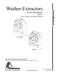
1
Installation
Washer-Extractors
Pocket Hardmount
Variable Speed
UW35AV
UW60AV
UW80AV
UW100AV
UW125AV
®
Para bajar una copia de estas instrucciones
en español, visite www.comlaundry.com
PHM1379C
PHM1379C
Keep These Instructions for Future Reference.
(If this machine changes ownership, this manual must accompany machine.)
www.comlaundry.com
Part No. F232228R2
June 2008
Table of
Contents
Safety Information..............................................................................
Explanation of Safety Messages...........................................................
Important Safety Instructions ...............................................................
Safety Decals ........................................................................................
Operator Safety.....................................................................................
2
2
2
4
5
Installation...........................................................................................
Delivery Inspection...............................................................................
Nameplate Location..............................................................................
Customer Service..................................................................................
Machine Dimensions Requirements .....................................................
Dimensional Clearances...................................................................
Machine Foundation Requirements......................................................
Floor Load Data....................................................................................
6
6
6
6
10
10
12
13
Specifications and Dimensions...........................................................
Mounting Bolt Hole Locations .............................................................
Mounting Bolt Installation Requirements........................................
Drain Connection Requirements...........................................................
Water Connection Requirements..........................................................
Electrical Installation Requirements.....................................................
Steam Requirements (Steam Heat Option Only)..................................
Chemical Injection Supply System.......................................................
Connecting External Liquid Supplies to the Washer-Extractor.......
14
14
18
21
23
25
29
30
31
© Copyright 2008, Alliance Laundry Systems LLC
All rights reserved. No part of the contents of this book may be reproduced or transmitted in any form or by any
means without the expressed written consent of the publisher.
F232228
© Copyright, Alliance Laundry Systems LLC – DO NOT COPY or TRANSMIT
1
Safety Information
Explanation of Safety Messages
Precautionary statements (“DANGER,” “WARNING,”
and “CAUTION”), followed by specific instructions,
are found in this manual and on machine decals. These
precautions are intended for the personal safety of the
operator, user, servicer, and those maintaining the
machine.
Important Safety Instructions
WARNING
To reduce the risk of fire, electric shock,
serious injury or death to persons when
using your washer, follow these basic
precautions:
W023
DANGER
DANGER indicates the presence of a
hazard that will cause severe personal
injury, death, or substantial property
damage if the danger is ignored.
WARNING
WARNING indicates the presence of a
hazard that can cause severe personal
injury, death, or substantial property
damage if the warning is ignored.
CAUTION
CAUTION indicates the presence of a
hazard that will or can cause minor
personal injury or property damage if the
caution is ignored.
Additional precautionary statements (“IMPORTANT”
and “NOTE”) are followed by specific instructions.
IMPORTANT: The word “IMPORTANT” is used
to inform the reader of specific procedures where
minor machine damage will occur if the procedure
is not followed.
NOTE: The word “NOTE” is used to communicate
installation, operation, maintenance or servicing
information that is important but not hazard
related.
1. Read all instructions before using the washer.
2. Refer to the GROUNDING INSTRUCTIONS in
the INSTALLATION manual for the proper
grounding of the washer.
3. Do not wash textiles that have been previously
cleaned in, washed in, soaked in, or spotted with
gasoline, kerosene, waxes, cooking oils, drycleaning solvents, or other flammable or
explosive substances as they give off vapors that
could ignite or explode.
4. Do not add gasoline, dry-cleaning solvents, or
other flammable or explosive substances to the
wash water. These substances give off vapors that
could ignite or explode.
5. Under certain conditions, hydrogen gas may be
produced in a hot water system that has not been
used for two weeks or more. HYDROGEN GAS
IS EXPLOSIVE. If the hot water system has not
been used for such a period, before using a
washing machine or combination washer-dryer,
turn on all hot water faucets and let the water
flow from each for several minutes. This will
release any accumulated hydrogen gas. The gas is
flammable, do not smoke or use an open flame
during this time.
6. Do not allow children to play on or in the washer.
Close supervision of children is necessary when
the washer is used near children. This is a safety
rule for all appliances.
7. Before the washer is removed from service or
discarded, remove the door to the washing
compartment.
8. Do not reach into the washer if the wash drum is
moving.
2
© Copyright, Alliance Laundry Systems LLC – DO NOT COPY or TRANSMIT
F232228
Safety Information
9. Do not install or store the washer where it will be
exposed to water and/or weather.
10. Do not tamper with the controls.
11. Do not repair or replace any part of the washer, or
attempt any servicing unless specifically
recommended in the user-maintenance
instructions or in published user-repair
instructions that the user understands and has the
skills to carry out.
12. To reduce the risk of an electric shock or fire, DO
NOT use an extension cord or an adapter to
connect the washer to the electrical power source.
13. Use washer only for its intended purpose,
washing textiles.
14. Never wash machine parts or automotive parts in
the machine. This could result in serious damage
to the basket.
15. ALWAYS disconnect the washer from electrical
supply before attempting any service. Disconnect
the power cord by grasping the plug, not the cord.
16. Install the washer according to the
INSTALLATION INSTRUCTIONS. All
connections for water, drain, electrical power and
grounding must comply with local codes and be
made by licensed personnel when required.
17. To reduce the risk of fire, textiles which have
traces of any flammable substances such as
vegetable oil, cooking oil, machine oil,
flammable chemicals, thinner, etc., or anything
containing wax or chemicals such as in mops and
cleaning cloths, must not be put into the washer.
These flammable substances may cause the
fabric to catch on fire by itself.
18. Do not use fabric softeners or products to
eliminate static unless recommended by the
manufacturer of the fabric softener or product.
19. Keep washer in good condition. Bumping or
dropping the washer can damage safety features.
If this occurs, have washer checked by a qualified
service person.
F232228
20. If the supply cord is damaged, it must be replaced
by a special cord or assembly available from the
manufacturer or its service agent.
21. Be sure water connections have a shut-off valve
and that fill hose connections are tight. CLOSE
the shut-off valves at the end of each wash day.
22. Loading door MUST BE CLOSED any time the
washer is to fill, tumble or spin. DO NOT bypass
the loading door switch by permitting the washer
to operate with the loading door open.
23. Always read and follow manufacturer’s
instructions on packages of laundry and cleaning
aids. Heed all warnings or precautions. To reduce
the risk of poisoning or chemical burns, keep
them out of the reach of children at all times
(preferably in a locked cabinet).
24. Always follow the fabric care instructions
supplied by the textile manufacturer.
25. Never operate the washer with any guards and/or
panels removed.
26. DO NOT operate the washer with missing or
broken parts.
27. DO NOT bypass any safety devices.
28. Failure to install, maintain, and/or operate this
washer according to the manufacturer’s
instructions may result in conditions which can
produce bodily injury and/or property damage.
NOTE: The WARNINGS and IMPORTANT
SAFETY INSTRUCTIONS appearing in this
manual are not meant to cover all possible
conditions and situations that may occur. Common
sense, caution and care must be exercised when
installing, maintaining, or operating the washer.
Any problems or conditions not understood should be
reported to the dealer, distributor, service agent or the
manufacturer.
© Copyright, Alliance Laundry Systems LLC – DO NOT COPY or TRANSMIT
3
Safety Information
WARNING
CAUTION
This machine must be installed, adjusted,
and serviced by qualified electrical
maintenance personnel familiar with the
construction and operation of this type of
machinery. They must also be familiar
with the potential hazards involved.
Failure to observe this warning may result
in personal injury and/or equipment
damage, and may void the warranty.
SW004
IMPORTANT: Ensure that the recommended
clearances for inspection and maintenance
are provided. Never allow the inspection and
maintenance space to be blocked.
Be careful around the open door,
particularly when loading from a level
below the door. Impact with door edges
can cause personal injury.
SW025
WARNING
Never touch internal or external steam
pipes, connections, or components.
These surfaces can be extremely hot and
will cause severe burns. The steam must
be turned off and the pipe, connections,
and components allowed to cool before
the pipe can be touched.
SW014
WARNING
Install the machine on a level floor of
sufficient strength. Failure to do so may
result in conditions which can produce
serious injury, death and/or property
damage.
W703
Safety Decals
Safety decals appear at crucial locations on the
machine. Failure to maintain legible safety decals
could result in injury to the operator or service
technician.
To provide personal safety and keep the machine in
proper working order, follow all maintenance and
safety procedures presented in this manual. If
questions regarding safety arise, contact the
manufacturer immediately.
Use manufacturer-authorized spare parts to avoid
safety hazards.
4
© Copyright, Alliance Laundry Systems LLC – DO NOT COPY or TRANSMIT
F232228
Safety Information
Operator Safety
Do not bypass any safety devices in the machine.
WARNING
WARNING
NEVER insert hands or objects into
basket until it has completely stopped.
Doing so could result in serious injury.
SW012
To ensure the safety of machine operators, the
following maintenance checks must be performed
daily:
Never operate the machine with a
bypassed or disconnected balance
system. Operating the machine with
severe out-of-balance loads could result
in personal injury and serious equipment
damage.
SW039
1. Prior to operating the machine, verify that all
warning signs are present and legible. Missing or
illegible signs must be replaced immediately.
Make certain that spares are available.
2. Check door interlock before starting operation of
the machine:
a. Attempt to start the machine with the door
open. The machine should not start with the
door open.
b. Close the door without locking it and attempt
to start the machine. The machine should not
start with the door unlocked.
c. Close and lock the door and start a cycle.
Attempt to open the door while the cycle is in
progress. The door should not open.
If the door lock and interlock are not functioning
properly, call a service technician.
3. Do not attempt to operate the machine if any of
the following conditions are present:
a. The door does not remain securely locked
during the entire cycle.
b. Excessively high water level is evident.
c. Machine is not connected to a properly
grounded circuit.
F232228
© Copyright, Alliance Laundry Systems LLC – DO NOT COPY or TRANSMIT
5
Installation
This manual is designed as a guide to the installation
of the Pocket Hardmount washer-extractor equipped
with the AC inverter drive.
NOTE: All information, illustrations, and
specifications contained in this manual are based
on the latest product information available at the
time of printing. We reserve the right to make
changes at any time without notice.
Customer Service
If literature or replacement parts are required, contact
the source from whom the washer-extractor was
purchased or contact Alliance Laundry Systems LLC
at (920) 748-3950 for the name of the nearest
authorized parts distributor.
For technical assistance, call:
(920) 748-3121
Ripon, Wisconsin
Delivery Inspection
Upon delivery, visually inspect crate protective cover,
and unit for any visible shipping damage. If the crate,
protective cover, or unit is damaged or signs of
possible damage are evident, have the carrier note the
condition on the shipping papers before the shipping
receipt is signed, or advise the carrier of the condition
as soon as it is discovered.
A record of each washer-extractor is on file with the
manufacturer. The serial number decal is located on
the left side of the control module at the rear of the
machine. Figure 1 shows an example of the serial
number on the nameplate. Always provide the
machine’s serial number and model number when
ordering parts or when seeking technical assistance.
Remove the crate and protective cover as soon after
delivery as possible. If any damage is discovered upon
removal of the crate and/or protective cover, advise the
carrier and file a written claim immediately.
Nameplate Location
The nameplate is located at the rear of the machine and
near supply valves. Always provide the machine’s
serial number and model number when ordering parts
or when seeking technical assistance. Refer to
Figure 1.
2
1
1
2
3
4
5
6
<
<
P
U
S
H
PHM615N
PHM615N
1
2
Near Supply Valves
Top of Module
Figure 1
6
© Copyright, Alliance Laundry Systems LLC – DO NOT COPY or TRANSMIT
F232228
Installation
Model Number Familiarization Guide
Sample Model Number: UW60AVXU80001
UW
Model Number Prefix
60
Washer-Extractor Capacity (pounds dry weight of laundry)
A
Type of Electrical Control
A = A-Control
V
Washer-Extractor Speed Capabilities
V = Variable Speed
X
Electrical Characteristics
See Electrical Specifications Chart in this section.
U8
0001
Design Series
Option Identification (varies from machine to machine)
UW60AVXU80001
00000000000
200 – 240
15
50 – 60
2/3
60
N/A
10
S3
27
N/A
594
0.0
Drawings:
ETL Listed
Conforms To ANSI/UL Std. 1206, 3rd Ed
Certified To CAN/CSA Std. C22.2 No.53-1968
EXAMPLE OF NAMEPLATE
PHM625N
PHM625N
Figure 2
F232228
© Copyright, Alliance Laundry Systems LLC – DO NOT COPY or TRANSMIT
7
Installation
.
UWAV Pocket Hardmount General Specifications
Specifications
35
60
80
100
125
Overall width, in (mm)
32.5 (826)
36.625 (930)
41.5 (1054)
41.5 (1054)
48 (1219)
Overall height, in (mm)
55.5 (1410)
64.5 (1638)
68.5 (1740)
68.5 (1740)
72 (1829)
Overall depth, in (mm)
43.625 (1108)
45 (1143)
51.5 (1308)
54.5 (1384)
58 (1473)
Overall Dimensions
Weight and Shipping Information
Net weight, lb (kg)
750 (341)
1229 (559)
1640 (744)
1680 (762)
2211 (1005)
Domestic shipping weight, lb (kg)
800 (361)
1268 (575)
1705 (773)
1745 (792)
2525 (1148)
66 (1.9)
84 (2.4)
119 (3.4)
119 (3.4)
166 (4.7)
Domestic shipping dimensions,
WxDxH, in (mm)
38x47x64
(970x1200x1630)
40x49x74.5
(1016x1245x1892)
44x60.5x77.25
(1118x1537x1962)
44x60.5x77.25
(1118x1537x1962)
61.5x60x77.75
(1560x1520x1980)
Export shipping weight, lb (kg)
910 (413)
1392 (631)
1900 (863)
1940 (881)
2591 (1178)
78 (2.2)
96 (2.7)
134 (3.8)
134 (3.8)
184 (5.3)
41x50x65.5
(1050x1280x1670)
43x52x72.5
(1092x1324x1892)
47x63.5x76
(1194x1613x1962)
47x63.5x76
(1194x1613x1962)
59x63x80
(1620x1610x2030)
Cylinder diameter, in (mm)
26.25 (667)
32 (813)
36 (914)
36 (914)
42 (1067)
Cylinder depth, in (mm)
18.375 (467)
20 (508)
21 (533)
27 (686)
24 (610)
Cylinder volume, ft3 (l)
5.76 (163)
9.31 (264)
12.4 (350)
15.9 (450)
19.2 (544)
Perforation size, in (mm)
.1875 (4.8)
.1875 (4.8)
.1875 (4.8)
.1875 (4.8)
.1875 (4.8)
Perforation open area, %
18
22
23
23
24
Door opening size, in (mm)
14.375 (365)
17.5 (445)
17.5 (445)
17.5 (445)
20 (508)
Height of door bottom above floor,
in (mm)
23.75 (603)
28.25 (718)
29 (737)
29 (737)
29 (737)
HOT
45 (170)
61 (231)
90 (341)
106 (401)
114 (431)
COLD
24 (91)
29 (110)
41 (155)
47 (178)
52 (197)
78 (295)
102 (386)
139 (526)
161 (609)
168 (636)
Average power used per cycle, kW/hr
0.18
0.28
0.40
0.40
0.48
Average HVAC load, BTU/hr (kcal/hr)
800 (202)
950 (240)
1050 (265)
1150 (290)
1200 (302)
Domestic shipping volume, ft3 (m3)
Export shipping volume, ft3 (m3)
Export shipping dimensions,
WxDxH, in (mm)
Wash Cylinder Information
Door Opening Information
Water Consumption
Average water
consumption per
cycle, gal (l)
Average hot water used per hour, gal (l)
Power Consumption
8
© Copyright, Alliance Laundry Systems LLC – DO NOT COPY or TRANSMIT
F232228
Installation
UWAV Pocket Hardmount General Specifications (Continued)
Specifications
35
60
80
100
125
1
1
1
1
1
2.3 (1.7)
2.9 (2.2)
5.0 (3.7)
5.0 (3.7)
7.5 (5.6)
Drive Train Information
Number of motors in drive train
Drive motor power, hp (kW)
Cylinder Speeds / Centrifugal Force Data
1/2 Wash/reverse, rpm (g)
26 (.25)
26 (.31)
26 (.35)
26 (.35)
26 (.40)
Wash/reverse, rpm (g)
42 (.66)
40 (.73)
40 (.82)
40 (.82)
37 (.82)
Distribution, rpm (g)
83 (2.57)
71 (2.29)
73 (2.57)
70 (2.50)
62 (2.29)
High extract 1, rpm (g)
328 (40)
297 (40)
280 (40)
280 (40)
260 (40)
High extract 2, rpm (g)
534 (106)
483 (106)
456 (106)
456 (106)
422 (106)
High extract 3, rpm (g)
656 (160)
594 (160)
560 (160)
560 (160)
518 (160)
Vibration safety switch installed
N/A
STD
STD
STD
STD
Safety switch gap setting, in (mm)*
N/A
.008 (.20) GO
.010 (.25) NO-GO
.008 (.20) GO
.010 (.25) NO-GO
.008 (.20) GO
.010 (.25) NO-GO
.006 (.15) GO
.008 (.20) NO-GO
Steam inlet connection size, in
.5
.5
.5
.5
.75
Number of steam inlets
1
1
1
1
1
LOW
2.1 (1.5)
3.3 (2.4)
4.6 (3.3)
5.7 (4.1)
6.7 (4.9)
MED
2.3 (1.7)
3.7 (2.6)
5.2 (3.8)
6.5 (4.7)
7.8 (5.6)
HIGH
2.7 (1.9)
4.1 (2.9)
6.1 (4.4)
7.6 (5.5)
9.1 (6.6)
1.4 (21.4)
2.1 (33.4)
3.1 (48.4)
3.8 (60.4)
4.6 (72.0)
15.6
25.2
37.8
37.8
50.4
6
6
9
9
12
2.6
4.2
4.2
4.2
4.2
LOW
2.4 (3.6)
2.4 (3.7)
2.2 (3.4)
2.8 (4.2)
2.5 (3.8)
MED
2.7 (4.1)
2.7 (4.1)
2.5 (3.9)
3.2 (4.8)
2.9 (4.4)
HIGH
3.1 (4.7)
3.0 (4.6)
3.0 (4.5)
3.7 (5.6)
3.4 (5.1)
Balance Detection
Direct Steam Heating (Optional)
Steam required to
raise bath
temperature
10°F, lb (10°C, kg)
Average consumption per cycle, bhp (kg)
Electrical Heating (Optional)
Total electrical heating capacity, kW
Number of electrical heating elements
Electrical heating element size, kW
Time required to
raise bath
temperature
10°F, min (10°C,
min)
* Gap setting should be made with “GO-NO-GO” type feeler gauge.
F232228
© Copyright, Alliance Laundry Systems LLC – DO NOT COPY or TRANSMIT
9
Installation
Machine Dimensions Requirements
Dimensional Clearances
Allow a minimum of 24 inches (60 cm) at the rear and
18 inches (45 cm) at the sides for maintenance,
inspection, and adjustment. Allow at least 18 inches
(45 cm) between machines in multiple installations.
Machine dimensions are indicated in Figure 3 and
specified in Table 1.
NOTE: The dimensions shown here are for
planning purposes only. They are approximate and
subject to normal manufacturing tolerances. If
exact dimensions are required for construction
purposes, contact the distributor or the
manufacturer. We reserve the right to make
changes at any time without notice.
UWAV Pocket Hardmount Machine Dimensions (Refer to Figure 3.)
35
60
80
100
125
Dimension
in.
mm
in.
mm
in.
mm
in.
mm
in.
mm
A
30.125
765
35.625
905
41.125
1045
41.125
1045
48
1219
B
32.5
826
36.625
930
41.5
1054
41.5
1054
48
1219
C
23.75
603
28.25
718
29
737
29
737
29
737
D
43.625
972
45
1143
51.5
1308
54.5
1384
58
1473
E
1
25
1
25
3
76
3
76
1.5
38
F
55.5
1410
64.5
1638
68.5
1740
68.5
1740
72
1829
G
30.5
775
36
914
43.75
1111
43.75
1111
48
1219
H
7.625
194
15.5
394
16.875
429
16.875
429
11.375
289
I
43.875
1114
55
1397
58.5
1486
58.5
1486
63.375
1610
Table 1
10
© Copyright, Alliance Laundry Systems LLC – DO NOT COPY or TRANSMIT
F232228
Installation
1
2
1
2
3
4
5
6
<
<
3
F
E
C
G (BASE)
A (BASE)
B (OVERALL)
D (OVERALL)
4
5
6
7
I
H
PHM623N
1
2
3
4
Supply Valve Box
Supply Dispenser
Door Handle
Water Inlet Valve
5
6
7
Power Input Area (Inside)
Steam Connector (Optional)
Drain
Figure 3
F232228
© Copyright, Alliance Laundry Systems LLC – DO NOT COPY or TRANSMIT
11
Installation
Machine Foundation Requirements
A proper foundation is absolutely necessary for the
washer-extractor because of the high extract speed and
the G-forces exerted.
NOTE: Do not mount on wooden floors, above
ground level, or over basements. Installation must
be “slab on grade” or equal.
Thoroughness of detail must be stressed with all
foundation work to ensure a stable unit installation,
eliminating possibilities of excessive vibration during
extract.
A concrete base designed to elevate the washerextractor to a comfortable and more accessible height
for loading and unloading laundry may be used. Care
must be exercised in the design of such a base due to
the force exerted by the machine during extract. This
base must be adequately tied in to the existing floor.
Static and dynamic loads on the floor or foundation are
shown in Table 2. This table can be used as a reference
when designing floors and foundations.
CAUTION
Ensure that the machine is installed on a
level floor of sufficient strength and that
the recommended clearances for
inspection and maintenance are provided.
Never allow the inspection and
maintenance space to be blocked.
SW020
The washer-extractor must be anchored to a smooth
level surface so that the entire base of the machine is
supported and rests on the mounting surface. (Do not
support the washer-extractor on only four points.)
12
© Copyright, Alliance Laundry Systems LLC – DO NOT COPY or TRANSMIT
F232228
Installation
Floor Load Data
UW A-Control, Variable Speed Pocket Hardmount
Specifications
UW35AV 160g
UW60AV 160g
Static Load Pressure, kN/sq m
6.33
7.77
8.46
9.18
9.16
Static Load Pressure, lbs/sq ft
132
162
177
192
191
Total Dynamic Load, kN*
5.0
8.6
11.4
14.2
17.8
Total Dynamic Load, lbs*
1122
1922
2562
3203
3996
7.1
10.3
9.8
12.3
11.9
Dynamic Load Pressure, lbs/sq ft
149
216
205
256
249
Dynamic Load Freq, Hz
10.9
9.9
9.3
9.3
8.6
Maximum Vertical Load, kN†
8.5
13.7
19.1
22.3
28.3
Maximum Vertical Load, lbs†
1917
3073
3073
5002
6358
Minimum Vertical Load, kN††
1.45
3.43
3.43
6.24
7.27
Minimum Vertical Load, lbs††
Dynamic Load Pressure, kN/sq m
UW80AV 160g UW100AV 160g UW125AV 160g
326.62
770.90
823.07
1403.64
1634.52
Maximum Moment about Machine Base,
kN-m
3.9
8.2
11.3
14.1
18.0
Maximum Moment about Machine Base,
lb-ft
2893
6053
8322
10,403
13,243
Table 2
† Acting
in the downward direction against the floor.
†† Acting
F232228
in the upward direction against the floor.
© Copyright, Alliance Laundry Systems LLC – DO NOT COPY or TRANSMIT
13
Specifications and Dimensions
Mounting Bolt Hole Locations
28.625 in.
(727 mm)
0.75 in.
(19 mm)
30.5 in.
(775 mm)
39.03 in.
(991 mm)
29 in.
(737 mm)
35.125 in.
(892 mm)
26.125 in.
(664 mm)
2 in.
(51 mm)
22.75 in.
(578 mm)
2 in.
(51 mm)
30.125 in.
(765 mm)
UW35AV
FRONT OF MACHINE
PHM661N
PHM661N
Figure 4
IMPORTANT: Drawing is not to scale.
14
© Copyright, Alliance Laundry Systems LLC – DO NOT COPY or TRANSMIT
F232228
Specifications and Dimensions
0.75 in.
(19 mm)
34.125 in.
(867 mm)
0.75 in.
(19 mm)
4.8125 in.
(122 mm)
0.75 in.
(19 mm)
46.8125 in.
(1189 mm)
9 in.
(229 mm)
1.25 in.
(32 mm)
44.8125 in.
(1138 mm)
36 in.
(914 mm)
39.25 in.
(997 mm)
1.25 in.
(32 mm)
21.4375 in.
(544 mm)
0.75 in.
(19 mm)
2 in.
(51 mm)
31.625 in.
(803 mm)
35.625 in.
(905 mm)
2 in.
(51 mm)
PHM662N
UW60AV
FRONT OF MACHINE
PHM662N
Figure 5
IMPORTANT: Drawing is not to scale.
F232228
© Copyright, Alliance Laundry Systems LLC – DO NOT COPY or TRANSMIT
15
Specifications and Dimensions
0.75 in.
(19 mm)
39.63 in.
(1008 mm)
0.75 in.
(19 mm)
6.75 in.
(171 mm)
9 in.
(229 mm)
52.1875 in.
(1326 mm)
43.75 in.
(1111 mm)
2.25 in.
(57 mm)
46.3125 in.
(1176 mm)
13.625 in.
(346 mm)
2.25 in.
(57 mm)
39.75 in.
(1010 mm)
13.625 in.
(346 mm)
0.75 in.
(19 mm)
3 in.
(76 mm)
35.125 in.
(892 mm)
3 in.
(76 mm)
41.25 in.
(1045 mm)
PHM663N
UW80AV AND UW100AV
FRONT OF MACHINE
PHM663N
Figure 6
IMPORTANT: Drawing is not to scale.
16
© Copyright, Alliance Laundry Systems LLC – DO NOT COPY or TRANSMIT
F232228
Specifications and Dimensions
0.75 in.
(19 mm)
46.25 in.
(1181 mm)
0.75 in.
(19 mm)
7 in.
(178 mm)
10 in.
(254 mm)
61.5 in.
(1562 mm)
48 in.
(1219 mm)
15 in.
(381 mm)
55.47 in.
(1409 mm)
48.94 in.
(1243 mm)
15.25 in.
(387 mm)
23.25 in.
(591 mm)
23.25 in.
(591 mm)
0.75 in.
(19 mm)
48 in.
(1219 mm)
UW125AV
PHM664N
FRONT OF MACHINE
PHM664N
Figure 7
IMPORTANT: Drawing is not to scale.
F232228
© Copyright, Alliance Laundry Systems LLC – DO NOT COPY or TRANSMIT
17
Specifications and Dimensions
Mounting Bolt Installation Requirements
A bolt kit consisting of eight bolts is available as an
option. The UW35AV uses 5/8-11 x 8 inch bolts. The
UW60AV, UW80AV, UW100AV and UW125AV use
3/4-10 x 8 inch bolts. The bolts should be embedded in
a 3500 psi minimum reinforced concrete floor that is a
minimum of 12 inches thick. Use the mounting bolt
layouts in Figure 8 and Figure 9. (The front of the
washer-extractor is the bottom of each diagram.)
A bolt-locator fixture or rebar frame is available as an
option. This rigid welded assembly made of
reinforcing rod and mounting bolts is designed to be
embedded in concrete. Refer to Figure 9.
1
2
3
The threaded end of the bolts should extend 2 inches
above the surface of the floor.
Refer to Figure 8 for a typical installation of individual
mounting bolts.
4
0.75 in.
(19 mm)
1
2
PHM179N
PHM179N
2 in.
(51 mm)
1
2
3
4
8 in.
(203 mm)
Machine Base
Mounting Bolt Threads
Grouting
Reinforcing Rod
Figure 9
PHM178N
1
2
Frame
Grout
Figure 8
18
© Copyright, Alliance Laundry Systems LLC – DO NOT COPY or TRANSMIT
F232228
Specifications and Dimensions
If the existing floor is not reinforced concrete at least
6 inches (153 mm) thick over a solid foundation, cut a
hole approximately 5 feet (1.52 m) square through the
existing floor. Excavate to a depth of 6 inches
(153 mm) from the top of the existing floor. Produce a
pyramid-shaped hole by excavating the bottom of the
hole to a width 6 inches (153 mm) wider on each side
than the width of the top of the hole. Fill with 6 inches
(153 mm) of reinforced concrete. Embed the mounting
bolts or base frame as the concrete is poured. Ensure
that the bolt threads extend 2 inches (51 mm) above
floor level.
9. After the grout is completely dry, tighten the
locknuts by even increments – one after the
other – until all are tightened evenly and the
washer-extractor is fastened securely to the floor.
NOTE: Check and retighten the locknuts after five
to ten days of operation and every month thereafter.
10. Check vibration safety switch and gap setting and
switch function.
After the concrete has cured, proceed as follows:
1. Place the washer-extractor adjacent to the
foundation. Do not attempt to move the machine
by pushing on the sides. Always insert a pry bar
or other device under the bottom frame of the
machine to move it.
7.3125 in.
(186 mm)
30.5 in.
(775 mm)
11 in.
(279 mm)
2. Remove the wood skid by unscrewing the
carriage bolts holding the skid to the bottom
frame of the washer-extractor.
3. Place the washer-extractor carefully over the
anchor bolts. Never attempt to lift the machine by
the door handle or by pushing on the cover panels.
UW35AV
8. Position the mounting bolt washers and locknuts
on the anchor bolts and fingertighten locknuts to
machine base.
F232228
PHM570N
PHM570N
Figure 10
5. Fill the space between the washer-extractor base
and the floor with a good quality non-shrinking
machinery grout to ensure a stable installation.
Grout completely under all frame members.
(Remove front panel and metal back panel to
gain access to all frame members.) Refer to
Figures 10 through 13. Force grout under
machine base until all voids are filled.
7. Before grout sets completely, make a drain
opening in the rear of the washer-extractor
grouting with a stiff piece of wire; this opening
should be approximately 1/2 inch (13 mm) wide
to allow any surface water build-up under the
base of the machine to drain away. Do not omit
this step.
4.0625 in.
(103 mm)
Typical
30.125 in.
(765 mm)
4. Raise and level the washer-extractor 1/2 inch
(13 mm) off the floor on three points, using
spacers such as nut fasteners.
6. Remove the spacers carefully, allowing the
machine to settle into the wet grout.
4.0625 in.
(103 mm)
Typical
35.625 in.
(905 mm)
4.0625 in.
(103 mm)
Typical
9.125 in.
(232 mm)
36 in.
(914 mm)
14.5 in.
(368 mm)
28 in.
(711 mm)
4.0625 in.
(103 mm)
Typical
UW60AV
PHM571N
PHM571N
Figure 11
© Copyright, Alliance Laundry Systems LLC – DO NOT COPY or TRANSMIT
19
Specifications and Dimensions
41.125 in.
(1044 mm)
13.875
in.
48 in.
(1219 mm) 3.25 in.
(83 mm)
24.3125 in.
(617 mm)
10.875 in.
(276 mm)
43.8125 in.
(1113 mm)
20.6875 in.
(526 mm)
4.0625 in.
(103 mm)
Typical
33 in.
(838 mm)
4.0625 in.
(103 mm)
Typical
48 in.
(1219 mm)
39.875 in.
1013 mm)
22 in.
(559 mm)
4.0625 in.
(103 mm)
Typical
UW80AV AND UW100AV
UW125AV
PHM192N
Figure 12
20
4.0625 in.
(103 mm)
Typical
PHM180N
Figure 13
© Copyright, Alliance Laundry Systems LLC – DO NOT COPY or TRANSMIT
F232228
Specifications and Dimensions
Drain Connection Requirements
A drain system of adequate capacity is essential to
washer-extractor performance. Ideally, the water
should empty through a vented pipe directly into a
sump or floor drain. Figure 14 and Figure 15 show
drain line and drain trough configurations.
Before any deviation from specified installation
procedures is attempted, the customer or installer
should contact the distributor.
Increasing the drain hose length, installing elbows, or
causing bends will decrease drain flow rate and
increase drain times, impairing washer-extractor
performance.
1
2
1 ft.
(30.48 cm)
3
4
5
6
7
PHM620N
Figure 14
A flexible connection must be made to a vented drain
system to prevent an air lock and to prevent siphoning.
IMPORTANT: Washer-extractor must be installed
in accordance with all local codes and ordinances.
IMPORTANT: The top of the vent must be 1 foot
(30 cm) lower than the bottom of the dispenser.
If proper drain size is not available or practical, a surge
tank is required. A surge tank in conjunction with a
sump pump should be used when gravity drainage is
not possible, such as in below-ground-level
installations.
F232228
PHM621N
1
2
3
4
5
6
7
Rear of Machine
Drain Pipe
1 Inch Minimum Air Gap
Steel Grate
Drain Trough
Strainer
Waste Line
Figure 15
Refer to Table 3 for capacity-specific drain
information.
Installation of additional washer-extractors will
require proportionately larger drain connections. Refer
to Table 4.
© Copyright, Alliance Laundry Systems LLC – DO NOT COPY or TRANSMIT
21
Specifications and Dimensions
Refer to Table 3 for capacity-specific drain
information.
Installation of additional washer-extractors will require
proportionately larger drain connections. Refer to
Table 4.
UWAV Pocket Hardmount
Drain Information
Specifications
Drain connection size, I.D., in (mm)
With second drain:
35
60
80
100
125
2.375 (60)
3 (76)
3 (76)
3 (76)
3 (76)
1
1
1
1
1
35 (132)
64 (242)
64 (242)
64 (242)
70 (265)
5 (142)
6 (170)
9 (255)
11 (311)
13 (368)
Number of drain outlets
Drain flow capacity, gal/min (l/min)
3
Recommended drain pit size, ft (l) †
†Sized for one machine using overflow level.
Table 3
UWAV Pocket Hardmount
Drain Line Sizing
Minimum Drain I.D., in (mm)
Model
Number of Machines
1
2
3
4
35
3 (76.2)
3 (76.2)
3.5 (88.9)
4 (102)
60
3 (76.2)
4 (102)
6 (152)
6 (152)
80
4 (102)
4 (102)
4 (102)
6 (152)
100
4 (102)
4 (102)
4 (102)
6 (152)
125
4 (102)
4 (102)
4 (102)
6 (152)
Table 4
22
© Copyright, Alliance Laundry Systems LLC – DO NOT COPY or TRANSMIT
F232228
Specifications and Dimensions
Water Connection Requirements
WARNING
To avoid personal injury, recommended
inlet water temperature should be no
higher than 125° Fahrenheit (51° Celsius).
W709
UWAV Pocket Hardmount
Water Supply Information
Specifications
Number of main fill water inlets
Main fill water inlet size, in (mm)
35
60
80/100
125
2
2
2
2
0.5 (12.7)
0.75 (19)
0.75 (19)
1 (25.4)
Recommended pressure psi (bar)
Inlet flow capacity (80 psi),
gal/min (l/min)
30-85 (2-5.7)
14 (53)
25 (95)
25 (95)
50 (189)
Table 5
Connections should be supplied by hot and cold water
lines of at least the sizes shown in Table 6. Installation
of additional machines will require proportionately
larger water lines.
If additional hose lengths are needed, use flexible
hoses with screen filters. Each hose should have a
screen filter installed to keep rust and other foreign
particles out of the water inlet valves.
To connect water service to machine with rubber
hoses, use the following procedure:
Pressure of 30 – 85 psi (2 – 5.7 bar) provides best
performance. Although the washer-extractor will
function properly at lower pressures, increased fill
times will occur.
1. Before installing hoses, flush the water system
for at least two minutes.
2. Check filters in the washer-extractor’s inlet hoses
for proper fit and cleanliness before connecting.
3. Hang the hoses in a large loop; do not allow them
to kink.
F232228
© Copyright, Alliance Laundry Systems LLC – DO NOT COPY or TRANSMIT
23
Specifications and Dimensions
Suitable air cushions should be installed in supply
lines to prevent “hammering.” Refer to Figure 16.
2
UWAV Pocket Hardmount
Water Supply Line Sizing
Model
35
60
80
100
125
Number
of Machines
Supply Line Size, in (mm)
Main
Hot/Cold
1
1 (25)
0.75 (19)
2
1.5 (38)
1 (25)
3
2 (50)
1.25 (32)
4
2 (50)
1.5 (38)
1
1.25 (32)
1 (25)
2
2 (50)
1.25 (32)
3
2 (50)
1.5 (38)
4
2.5 (64)
2 (50)
1
1 (25)
0.75 (20)
2
1.5 (38)
1 (25)
3
1.5 (38)
1.25 (32)
4
2 (50)
1.5 (38)
1
1 (25)
0.75 (20)
2
1.5 (38)
1 (25)
3
1.5 (38)
1.25 (32)
4
2 (50)
1.5 (38)
1
1.5 (38)
1 (25)
2
2 (50)
1.5 (38)
3
2.5 (64)
2 (50)
4
2.5 (64)
2 (50)
1
PHM184N
PHM184N
1
2
Water Supply Faucets
Air Cushions (Risers)
Figure 16
Table 6
24
© Copyright, Alliance Laundry Systems LLC – DO NOT COPY or TRANSMIT
F232228
Specifications and Dimensions
Electrical Installation Requirements
IMPORTANT: Electrical ratings are subject to
change. Refer to serial decal for electrical ratings
information specific to your machine.
WARNING
This machine must be installed, adjusted,
and serviced by qualified electrical
maintenance personnel familiar with the
construction and operation of this type of
machinery. They must also be familiar
with the potential hazards involved.
Failure to observe this warning may result
in personal injury and/or equipment
damage, and may void the warranty.
SW004
WARNING
Electrical connections are made at the rear of the
control module. The machine must be connected to the
proper electrical supply shown on the identification
plate attached to the side of the control module using
copper conductors only.
The AC inverter drive requires a clean power supply
free from voltage spikes and surges. A voltage monitor
should be used to check incoming power. The
customer’s local power company may provide such a
monitor.
IMPORTANT: Alliance Laundry Systems
warranty does not cover compounds that fail as a
result of improper input voltage.
If input voltage measures above 240 Volt for a
200 Volt drive or above 480 Volt for a 400 Volt drive,
ask the power company to lower the voltage. As an
alternative, a step-down transformer kit is available
from the distributor. Voltages above 250 Volt and
490 Volt require additional measures. Contact the
distributor or the manufacturer for assistance.
Dangerous voltages are present in the
electrical control box(es) and at the motor
terminals. Only qualified personnel
familiar with electrical test procedures,
test equipment, and safety precautions
should attempt adjustments and
troubleshooting. Disconnect power from
the machine before removing the control
box cover, and before attempting any
service procedures.
SW005
WARNING
Ensure that a ground wire from a proven
earth ground is connected to the ground
lug near the input power block on this
machine. Without proper grounding,
personal injury from electric shock could
occur and machine malfunctions may be
evident.
SW008
F232228
© Copyright, Alliance Laundry Systems LLC – DO NOT COPY or TRANSMIT
25
Specifications and Dimensions
WARNING
Never touch terminals or components of
the AC inverter drive unless power is
disconnected and the “CHARGE”
indicator LED is off. The AC inverter drive
retains potentially deadly voltage for
some time after the power is
disconnected. There are no userserviceable parts inside the AC inverter
drive. Tampering with the drive will void
the warranty.
SW009
The AC drive provides thermal overload protection for
the drive motor. However, a separate three-phase
circuit breaker must be installed for complete
electrical overload protection. This prevents damage to
the motor by disconnecting all legs if one should be
lost accidentally. Check the data plate on the side of
the washer-extractor or refer to Table 7 for circuit
breaker requirements.
NOTE: Do NOT use fuses in place of a circuit
breaker.
CAUTION
Do not use a phase adder on any variablespeed machine.
DANGER
SW037
When controlling the AC inverter drive
with a parameter unit, the machine’s
computer and its safety features are
bypassed. This would allow the basket to
rotate at high speeds with the door open.
When using a parameter unit to control
the AC inverter drive, a large sign should
be placed on the front of the machine
warning people of the imminent danger.
SW003
26
© Copyright, Alliance Laundry Systems LLC – DO NOT COPY or TRANSMIT
F232228
Specifications and Dimensions
The washer-extractor should be connected to an
individual branch circuit not shared with lighting or
other equipment.
1
Connections to
Control Module
The connection should be shielded in a liquid-tight or
approved flexible conduit with proper conductors of
correct size installed in accordance with the National
Electric Code or other applicable codes. The
connection must be made by a qualified electrician
using the wiring diagram provided with the washerextractor.
Use wire sizes indicated in the Electrical
Specifications chart for runs up to 50 feet (15 m). Use
next larger size for runs of 50 to 100 feet (15 to 30 m).
Use two sizes larger for runs greater than 100 feet
(30 m).
For personal safety and for proper operation, the
washer-extractor must be grounded in accordance with
state and local codes. If such codes are not available,
grounding must conform with the National Electric
Code, article 250-95. The ground connection must be
made to a proven earth ground, not to conduit or water
pipes.
2
(L1)
R
Black
(L2)
S
Blue
(L3)
T
Red
PHM572N
1
2
Grounding Lug: Connect to proven earth
ground
Power Input Block
Figure 17
If a delta supply system is used, the high leg should be
connected to L3.
After electrical installation is complete, run the
machine through a test cycle and check for a clockwise
basket rotation during the extract step. If rotation is not
clockwise, disconnect the power from the machine and
have a qualified electrician reverse any 2 motor leads at
the AC drive terminal block.
F232228
© Copyright, Alliance Laundry Systems LLC – DO NOT COPY or TRANSMIT
27
Specifications and Dimensions
UWAV Pocket Hardmount
Electrical Specifications
Voltage Designation
Wire
Full Load
Amps
Breaker
AWG
mm2
125
Phase
100
Cycle
80
Voltage
60
Code
Model
35
Standard
N
440-480
50-60
3
3
4
15
14
3x2.5
P
380-415
50-60
3
3
4
15
14
3x2.5
X
200-240
50-60
1/3
2/3
9
15
14
2/3x2.5
N
440-480
50-60
3
3
4
15
14
3x2.5
P
380-415
50-60
3
3
4
15
14
3x2.5
X
200-240
50-60
1/3
2/3
10
15
14
2/3x2.5
N
440-480
50-60
3
3
6
15
14
3x2.5
P
380-415
50-60
3
3
6
15
14
3x2.5
Q
200-240
50-60
3
3
9
25
14
3x6
N
440-480
50-60
3
3
6
15
14
3x2.5
P
380-415
50-60
3
3
6
15
14
3x2.5
Q
200-240
50-60
3
3
10
25
10
3x6
N
440-480
50-60
3
3
7
15
14
3x6
P
380-415
50-60
3
3
7
15
14
3x6
Q
200-240
50-60
3
3
13
25
10
3x6
Note: Wire sizes shown are for copper, THHN, 90° conductor per NEC article 310.
Table 7
28
© Copyright, Alliance Laundry Systems LLC – DO NOT COPY or TRANSMIT
F232228
Specifications and Dimensions
Steam Requirements
(Steam Heat Option Only)
For washer-extractors equipped with optional steam
heat, install piping in accordance with approved
commercial steam practices. Steam requirements are
shown in Table 8.
WARNING
NOTE: Failure to install the supplied steam filter
may void the warranty.
Never touch internal or external steam
pipes, connections, or components.
These surfaces can be extremely hot and
will cause severe burns. The steam must
be turned off and the pipe, connections,
and components allowed to cool before
the pipe can be touched.
SW014
UWAV Pocket Hardmount
Steam Supply Information
Specifications
35
60
80
100
125
Steam inlet connection, in (mm)
0.5 (DN13)
0.5 (DN13)
0.5 (DN13)
0.5 (DN13)
0.75 (DN19)
1
1
1
1
1
30 – 80
(2.0 – 5.5)
30 – 80
(2.0 – 5.5)
30 – 80
(2.0 – 5.5)
30 – 80
(2.0 – 5.5)
30 – 80
(2.0 – 5.5)
80 (5.5)
80 (5.5)
80 (5.5)
80 (5.5)
80 (5.5)
Number of steam inlets
Recommended pressure, psi (bar)
Maximum pressure, psi (bar)
Table 8
F232228
© Copyright, Alliance Laundry Systems LLC – DO NOT COPY or TRANSMIT
29
Specifications and Dimensions
Chemical Injection Supply System
1
WARNING
2
Wear eye and hand protection when
handling chemicals; always avoid direct
contact with raw chemicals. Read the
manufacturer’s directions for accidental
contact before handling chemicals.
Ensure an eye-rinse facility and an
emergency shower are within easy reach.
Check at regular intervals for chemical
leaks.
3
4
5
6
SW016
Undiluted chemical dripping can damage the washerextractor. Therefore, all chemical supply dispenser
pumps should be mounted below the washerextractor’s injection point. All dispenser tubing should
also run below the injection point. Loops do not
prevent drips if these instructions are not followed.
Failure to follow these instructions could damage the
machine and void the warranty. Figure 18 shows a
typical chemical injection supply system.
PHM559N
PHM559N
1
2
1
2
3
4
5
6
3
Tubing from Pump
Seal Nut
Tubing Ring
Base
Lid
Nut
Figure 19
PHM578N
1
2
3
Injection Point
Chemical Dispenser Pump Outlet
PVC Pipe
Figure 18
30
© Copyright, Alliance Laundry Systems LLC – DO NOT COPY or TRANSMIT
F232228
Specifications and Dimensions
Connecting External Liquid Supplies to
the Washer-Extractor
The UW35AV – UW125AV have a polypropylene
supply dispenser. Refer to Figure 20.
1. Remove knockout from supply dispenser. Refer
to Figure 19. Plugs are assembled inside the
tubing ring.
Do not attempt to make chemical injection electrical
connections to points other than those provided
specifically for that purpose by the factory.
2. Install PG connector in hole with strain reliefs,
included in the seal nut.
Chemical Injection Supply System
3. Insert tubes through base. Do not remove cups.
Tube should extend into the plastic cup, with the
exception of the softener tube, which should be
routed to the outside of the cup.
4. Tighten the seal nut to prevent tubing from
escaping the assembly.
Specifications
AV
Number of dry supply compartments
5
Number of liquid supply connections
5
Liquid supply connection size, in (mm)
.5 (12.7)
1
2
3
4
5
6
PHM553N
PHM553N
1
Strain Relief for Liquid Chemical Supply Lines
4
Dry Supply Cups
2
Supply Dispenser Lid
5
Dry Supply Insert
3
Nozzles
6
Polypropylene Supply Dispenser
IMPORTANT: Do not attach anything to nozzles. Air gap must be maintained.
Figure 20
F232228
© Copyright, Alliance Laundry Systems LLC – DO NOT COPY or TRANSMIT
31
Specifications and Dimensions
The external supply connection is located on the rear
panel of the control module. It houses a terminal strip
which furnishes supply output signals for the chemical
injection supply pumps. Refer to Figure 21 for
examples of applicable decals.
Terminals SUPPLY 1 through SUPPLY 5 provide
200 – 240VAC fused at 500mA. These terminals may
be used to provide signals to the chemical injection
system but must not be used to provide power to the
pump. Do not attempt to increase fuse rating as this
may cause damage to the washer-extractor’s circuitry.
An external chemical injection system requiring 200 –
240VAC can be powered through LINE 1 and LINE 2
on the external supply terminal strip on UWAVX and
UWAVQ models. Any chemical injection system used
with UWAVN or UWAVP models must be powered by
a separate external power source.
Any injection system pump which requires 110VAC
must be powered by a separate external power
source.
P AND N VOLTAGE MODELS (AVP AND AVN)
CAUTION
Attempting to obtain 110VAC by using L1
or L2 with the common may damage
laundry machine circuitry and/or the
chemical injection system. Using a
240VAC power wire in the washerextractor and an earth ground to obtain
110VAC could cause microprocessor
problems.
SW028
Refer to Chemical Injection Supply System
instructions for operational details.
X (AVX) AND Q (AVQ) VOLTAGE MODELS
PHM554N
PHM554N
Figure 21
32
© Copyright, Alliance Laundry Systems LLC – DO NOT COPY or TRANSMIT
F232228