1
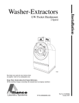
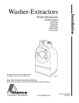
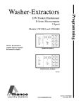
Washer-Extractors
Operation/Maintenance
UW Pocket Hardmount
B-Series Microcomputer
2 Speed
Models UW35B2 and UW60B2
®
NOTA: El manual en
español aparece después
del manual en inglés.
PHM1379C
PHM1379C
www.comlaundry.com
Part No. F232223R1
November 2005
Table of
Contents
Safety Information..............................................................................
Explanation of Safety Messages...........................................................
Important Safety Instructions ...............................................................
Key to Symbols.....................................................................................
Operator Safety .....................................................................................
Safe Operating Environment ................................................................
Environmental Conditions ...............................................................
Machine Location ............................................................................
Input and Output Services................................................................
3
3
3
6
8
8
8
9
9
Introduction.........................................................................................
Model Identification .............................................................................
Nameplate Location..............................................................................
Replacement Parts ................................................................................
Customer Service..................................................................................
11
11
11
11
11
Operation.............................................................................................
Machine Familiarization Guide ............................................................
Introduction...........................................................................................
Electronic Control Unit....................................................................
Control Output Fuse Board ..............................................................
Harnessing........................................................................................
Control Panel ........................................................................................
Summary of Major Features .................................................................
Rapid Advance Mode ......................................................................
Display Indicators.................................................................................
Operating Instructions ..........................................................................
13
13
14
14
14
14
15
16
16
17
19
Maintenance ........................................................................................
Daily .....................................................................................................
Beginning of Day .............................................................................
End of Day .......................................................................................
Weekly..................................................................................................
Monthly.................................................................................................
Quarterly ...............................................................................................
Care of Stainless Steel ..........................................................................
Daily Preventive Maintenance Checklist..............................................
Weekly Preventive Maintenance Checklist ..........................................
Monthly Preventive Maintenance Checklist.........................................
Quarterly Preventive Maintenance Checklist .......................................
21
21
21
21
21
22
25
26
27
28
29
30
© Copyright 2005, Alliance Laundry Systems LLC
All rights reserved. No part of the contents of this book may be reproduced or transmitted in any form or by any
means without the expressed written consent of the publisher.
F232223
© Copyright, Alliance Laundry Systems LLC – DO NOT COPY or TRANSMIT
1
Notes
2
© Copyright, Alliance Laundry Systems LLC – DO NOT COPY or TRANSMIT
F232223
Safety Information
Explanation of Safety Messages
Precautionary statements (“DANGER,” “WARNING,”
and “CAUTION”), followed by specific instructions,
are found in this manual and on machine decals. These
precautions are intended for the personal safety of the
operator, user, servicer, and those maintaining the
machine.
DANGER
DANGER indicates the presence of a
hazard that will cause severe personal
injury, death, or substantial property
damage if the danger is ignored.
WARNING
WARNING indicates the presence of a
hazard that can cause severe personal
injury, death, or substantial property
damage if the warning is ignored.
CAUTION
CAUTION indicates the presence of a
hazard that will or can cause minor
personal injury or property damage if the
caution is ignored.
Additional precautionary statements (“IMPORTANT”
and “NOTE”) are followed by specific instructions.
IMPORTANT: The word “IMPORTANT” is used
to inform the reader of specific procedures where
minor machine damage will occur if the procedure
is not followed.
NOTE: The word “NOTE” is used to communicate
installation, operation, maintenance or servicing
information that is important but not hazard
related.
Important Safety Instructions
WARNING
To reduce the risk of fire, electric shock,
serious injury or death to persons when
using your washer, follow these basic
precautions:
W023
1. Read all instructions before using the washer.
2. Refer to the GROUNDING INSTRUCTIONS in
the INSTALLATION manual for the proper
grounding of the washer.
3. Do not wash textiles that have been previously
cleaned in, washed in, soaked in, or spotted with
gasoline, kerosene, waxes, cooking oils, drycleaning solvents, or other flammable or
explosive substances as they give off vapors that
could ignite or explode.
4. Do not add gasoline, dry-cleaning solvents, or
other flammable or explosive substances to the
wash water. These substances give off vapors that
could ignite or explode.
5. Under certain conditions, hydrogen gas may be
produced in a hot water system that has not been
used for two weeks or more. HYDROGEN GAS
IS EXPLOSIVE. If the hot water system has not
been used for such a period, before using a
washing machine or combination washer-dryer,
turn on all hot water faucets and let the water
flow from each for several minutes. This will
release any accumulated hydrogen gas. The gas is
flammable, do not smoke or use an open flame
during this time.
6. Do not allow children to play on or in the washer.
Close supervision of children is necessary when
the washer is used near children. This is a safety
rule for all appliances.
7. Before the washer is removed from service or
discarded, remove the door to the washing
compartment.
8. Do not reach into the washer if the wash drum is
moving.
F232223
© Copyright, Alliance Laundry Systems LLC – DO NOT COPY or TRANSMIT
3
Safety Information
9. Do not install or store the washer where it will be
exposed to water and/or weather.
10. Do not tamper with the controls.
11. Do not repair or replace any part of the washer, or
attempt any servicing unless specifically
recommended in the user-maintenance
instructions or in published user-repair
instructions that the user understands and has the
skills to carry out.
12. To reduce the risk of an electric shock or fire, DO
NOT use an extension cord or an adapter to
connect the washer to the electrical power source.
13. Use washer only for its intended purpose,
washing textiles.
14. Never wash machine parts or automotive parts in
the machine. This could result in serious damage
to the basket.
15. ALWAYS disconnect the washer from electrical
supply before attempting any service. Disconnect
the power cord by grasping the plug, not the cord.
16. Install the washer according to the
INSTALLATION INSTRUCTIONS. All
connections for water, drain, electrical power and
grounding must comply with local codes and be
made by licensed personnel when required.
17. To reduce the risk of fire, textiles which have
traces of any flammable substances such as
vegetable oil, cooking oil, machine oil,
flammable chemicals, thinner, etc., or anything
containing wax or chemicals such as in mops and
cleaning cloths, must not be put into the washer.
These flammable substances may cause the
fabric to catch on fire by itself.
18. Do not use fabric softeners or products to
eliminate static unless recommended by the
manufacturer of the fabric softener or product.
20. Replace worn power cords and/or loose plugs.
21. Be sure water connections have a shut-off valve
and that fill hose connections are tight. CLOSE
the shut-off valves at the end of each wash day.
22. Loading door MUST BE CLOSED any time the
washer is to fill, tumble or spin. DO NOT bypass
the loading door switch by permitting the washer
to operate with the loading door open.
23. Always read and follow manufacturer’s
instructions on packages of laundry and cleaning
aids. Heed all warnings or precautions. To reduce
the risk of poisoning or chemical burns, keep
them out of the reach of children at all times
(preferably in a locked cabinet).
24. Always follow the fabric care instructions
supplied by the textile manufacturer.
25. Never operate the washer with any guards and/or
panels removed.
26. DO NOT operate the washer with missing or
broken parts.
27. DO NOT bypass any safety devices.
28. Failure to install, maintain, and/or operate this
washer according to the manufacturer’s
instructions may result in conditions which can
produce bodily injury and/or property damage.
NOTE: The WARNINGS and IMPORTANT
SAFETY INSTRUCTIONS appearing in this
manual are not meant to cover all possible
conditions and situations that may occur. Common
sense, caution and care must be exercised when
installing, maintaining, or operating the washer.
Any problems or conditions not understood should be
reported to the dealer, distributor, service agent or the
manufacturer.
19. Keep washer in good condition. Bumping or
dropping the washer can damage safety features.
If this occurs, have washer checked by a qualified
service person.
4
© Copyright, Alliance Laundry Systems LLC – DO NOT COPY or TRANSMIT
F232223
Safety Information
WARNING
WARNING
This machine must be installed, adjusted,
and serviced by qualified electrical
maintenance personnel familiar with the
construction and operation of this type of
machinery. They must also be familiar
with the potential hazards involved.
Failure to observe this warning may result
in personal injury and/or equipment
damage, and may void the warranty.
Never touch internal or external steam
pipes, connections, or components.
These surfaces can be extremely hot and
will cause severe burns. The steam must
be turned off and the pipe, connections,
and components allowed to cool before
the pipe can be touched.
SW014
SW004
WARNING
CAUTION
Ensure that the machine is installed on a
level floor of sufficient strength and that
the recommended clearances for
inspection and maintenance are provided.
Never allow the inspection and
maintenance space to be blocked.
SW020
This machine must be installed, adjusted,
and serviced by qualified electrical
maintenance personnel familiar with the
construction and operation of this type of
machinery. They must also be familiar
with the potential hazards involved.
Failure to observe this warning may result
in personal injury and/or equipment
damage, and may void the warranty.
SW004
CAUTION
Be careful around the open door,
particularly when loading from a level
below the door. Impact with door edges
can cause personal injury.
SW025
F232223
© Copyright, Alliance Laundry Systems LLC – DO NOT COPY or TRANSMIT
5
Safety Information
Key to Symbols
The lightning flash and arrowhead within the triangle
is a warning sign indicating the presence of dangerous
voltage.
The exclamation point within the triangle is a warning
sign indicating important instructions concerning the
machine and possibly dangerous conditions.
This warning symbol indicates the presence of
potentially dangerous drive mechanisms within the
machine. Guards should always be in place when the
machine is in operation.
6
This warning symbol indicates the presence of possibly
dangerous chemicals. Proper precautions should be
taken when handling corrosive or caustic materials.
This warning symbol indicates the presence of hot
surfaces that could cause serious burns. Stainless steel
and steam lines can become extremely hot and should
not be touched.
This warning symbol indicates the presence of
possibly dangerous pinch-points. Moving mechanical
parts can crush and/or sever body parts.
© Copyright, Alliance Laundry Systems LLC – DO NOT COPY or TRANSMIT
F232223
Safety Information
PHM600N
Figure 1
Safety decals appear at crucial locations on the
machine. Failure to maintain legible safety decals
could result in injury to the operator or service
technician.
Use manufacturer-authorized spare parts to avoid
safety hazards.
To provide personal safety and keep the machine in
proper working order, follow all maintenance and
safety procedures presented in this manual. If
questions regarding safety arise, contact the
manufacturer immediately.
F232223
© Copyright, Alliance Laundry Systems LLC – DO NOT COPY or TRANSMIT
7
Safety Information
Operator Safety
Safe Operating Environment
WARNING
NEVER insert hands or objects into
basket until it has completely stopped.
Doing so could result in serious injury.
SW012
To ensure the safety of machine operators, the
following maintenance checks must be performed
daily:
1. Prior to operating the machine, verify that all
warning signs are present and legible. Missing or
illegible signs must be replaced immediately.
Make certain that spares are available.
2. Check door interlock before starting operation of
the machine:
a. Attempt to start the machine with the door
open. The machine should not start with the
door open.
b. Close the door without locking it and attempt
to start the machine. The machine should not
start with the door unlocked.
c. Close and lock the door and start a cycle.
Attempt to open the door while the cycle is in
progress. The door should not open.
If the door lock and interlock are not functioning
properly, call a service technician.
3. Do not attempt to operate the machine if any of
the following conditions are present:
a. The door does not remain securely locked
during the entire cycle.
b. Excessively high water level is evident.
c. Machine is not connected to a properly
grounded circuit.
Do not bypass any safety devices in the machine.
WARNING
Never operate the machine with a
bypassed or disconnected balance
system. Operating the machine with
severe out-of-balance loads could result
in personal injury and serious equipment
damage.
Safe operation requires an appropriate operating
environment for both the operator and the machine. If
questions regarding safety arise, contact the
manufacturer immediately.
Environmental Conditions
• Ambient Temperature. Water in the machine will
freeze at temperatures of 32°F (0°C) or below.
Temperatures above 120°F (50°C) will result in
more frequent motor overheating and, in some
cases, malfunction or premature damage to solid
state devices that are used in some models.
Special cooling devices may be necessary.
Water pressure switches are affected by increases
and decreases in temperature. Every 25°F (10°C)
change in temperature will have a 1% effect on
the water level.
• Humidity. Relative humidity above 90% may
cause the machine’s electronics or motors to
malfunction or may trip the ground fault
interrupter. Corrosion problems may occur on
some metal components in the machine.
If the relative humidity is below 30%, belts and
rubber hoses may eventually develop dry rot.
This condition can result in hose leaks, which
may cause safety hazards external to the machine
in conjunction with adjacent electrical
equipment.
• Ventilation. The need for make-up air openings
for such laundry room accessories as dryers,
ironers, water heaters, etc., must be evaluated
periodically. Louvers, screens, or other
separating devices may reduce the available air
opening significantly.
• Radio Frequency Emissions. A filter is available
for machines in installations where floor space is
shared with equipment sensitive to radio
frequency emissions.
• Elevation. If the machine is to be operated at
elevations of over 3280 feet (1000 m) above sea
level, pay special attention to water levels and
electronic settings (particularly temperature) or
desired results may not be achieved.
• Chemicals. Keep stainless steel surfaces free of
chemical residues.
SW039
8
© Copyright, Alliance Laundry Systems LLC – DO NOT COPY or TRANSMIT
F232223
Safety Information
Input and Output Services
DANGER
Do not place volatile or flammable fluids
in any machine. Do not clean the machine
with volatile or flammable fluids such as
acetone, lacquer thinners, enamel
reducers, carbon tetrachloride, gasoline,
benzene, naptha, etc. Doing so could
result in serious personal injury and/or
damage to the machine.
SW002
• Water Damage. Do not spray the machine with
water. Short circuiting and serious damage may
result. Repair immediately all seepage due to
worn or damaged gaskets, etc.
Machine Location
• Foundation. The concrete floor must be of
sufficient strength and thickness to handle the
floor loads generated by the high extract speeds
of the machine. Refer to Installation manual.
• Service/Maintenance Space. Provide sufficient
space to allow comfortable performance of
service procedures and routine preventive
maintenance.
Consult installation instructions for specific details.
CAUTION
Replace all panels that are removed to
perform service and maintenance
procedures. Do not operate the machine
with missing guards or with broken or
missing parts. Do not bypass any safety
devices.
SW019
• Water Pressure. Best performance will be
realized if water is provided at a pressure of 30 –
85 psi (2.0 – 5.7 bar). Although the machine will
function properly at lower pressure, increased fill
times will occur. Water pressure higher than
100 psi (6.7 bar) may result in damage to
machine plumbing. Component failure(s) and
personal injury could result.
• Steam Heat (Optional) Pressure. Best
performance will be realized if steam is provided
at a pressure of 30 – 80 psi (2.0 – 5.4 bar). Steam
pressure higher than 125 psi (8.5 bar) may result
in damage to steam components and may cause
personal injury.
For machines equipped with optional steam heat,
install piping in accordance with approved
commercial steam practices. Failure to install the
supplied steam filter may void the warranty.
• Drainage System. Provide drain lines or troughs
large enough to accommodate the total number of
gallons that could be dumped if all machines on
the site drained at the same time from the highest
attainable level. If troughs are used, they should
be covered to support light foot traffic.
• Power. For personal safety and for proper
operation, the machine must be grounded in
accordance with state and local codes. The
ground connection must be to a proven earth
ground, not to conduit or water pipes. Do not use
fuses in place of the circuit breaker. An easyaccess cutoff switch should also be provided.
WARNING
Ensure that a ground wire from a proven
earth ground is connected to the ground
lug near the input power block on this
machine. Without proper grounding,
personal injury from electric shock could
occur and machine malfunctions may be
evident.
SW008
Always disconnect power and water supplies before a
service technician performs any service procedure.
Where applicable, steam and/or compressed air
supplies should also be disconnected before service is
performed.
F232223
© Copyright, Alliance Laundry Systems LLC – DO NOT COPY or TRANSMIT
9
Notes
10
© Copyright, Alliance Laundry Systems LLC – DO NOT COPY or TRANSMIT
F232223
Introduction
Model Identification
Replacement Parts
Information in this manual is applicable to these
models:
If literature or replacement parts are required, contact
the source from which the washer-extractor was
purchased or contact Alliance Laundry Systems LLC
at (920) 748-3950 for the name of the nearest
authorized parts distributor. A parts manual may be
ordered by returning the reply card provided with each
washer-extractor.
UW35B2
UW60B2
Nameplate Location
The nameplate is located on the cage wrap (below
plumbing bracket) and on top rear of the control
module. Always provide the machine’s serial number
and model number when ordering parts or when
seeking technical assistance. Refer to Figure 2.
Customer Service
For technical assistance, contact your local distributor
or call:
(920) 748-3121
Ripon, Wisconsin
1
2
A record of each washer-extractor is on file with the
manufacturer. Always provide the machine’s serial
number and model number when ordering parts or
when seeking technical assistance. Refer to Figure 2.
P
U
S
H
PHM598N
1
2
Top Rear of Control Module
Cage Wrap (Below Plumbing Bracket)
Figure 2
F232223
© Copyright, Alliance Laundry Systems LLC – DO NOT COPY or TRANSMIT
11
Introduction
Model Number Familiarization Guide
Sample Model Number: UW35B2OU80001
UW
Model Number Prefix
35
Washer-Extractor Capacity (pounds dry weight of laundry)
B
Type of Electrical Control
2
Washer-Extractor Speed Capabilities
O
Electrical Characteristics
U8
Design Series
0001
B = B – Control
Option Identification (varies from machine to machine)
UW35B2OU80001
00000000000
200 – 240
20
50 – 60
2/3
60
N/A
14
3
27
N/A
813
0.0
Drawings:
ETL Listed
Conforms To ANSI/UL Std. 1206, 3rd Ed
Certified To CAN/CSA Std. C22.2 No.53-1968
EXAMPLE OF NAMEPLATE
PHM599N
PHM599N
Figure 3
12
© Copyright, Alliance Laundry Systems LLC – DO NOT COPY or TRANSMIT
F232223
Operation
Machine Familiarization Guide
The machine familiarization guide in Figure 4
identifies major operational features of the
washer-extractor.
1
2
3
4
13
®
5
6
7
12
8
11
10
9
PHM1379C
PHM1379C
1
2
3
4
5
6
7
Emergency Stop Button
Door Unlock Button
Supply Valve Box
Supply Dispenser
Door Handle
Door Box
Door Latch Extension Arm
8
9
10
11
12
13
Door Latch
Side Panel
Rub Rail
Shell Front
Door Hinge
Control Module
Figure 4
F232223
© Copyright, Alliance Laundry Systems LLC – DO NOT COPY or TRANSMIT
13
Operation
Introduction
Control Output Fuse Board
This control is composed of the electronic control unit
and the control fuse board. Beyond this, there are
wiring harnesses associated with the control. Only an
authorized person should ever look inside the machine.
Before accessing the control components, first TURN
OFF POWER, then open the lid.
This portion of the control contains the power supply
for the control unit, and also the switching devices that
power the components in the machine, all of which are
on the output PC board. The output board has a cover
for back of hand protection. It must be in place at all
times during machine operation. The switching
devices are controlled by the control unit, and are solid
state components which provide two important
benefits: 1) elimination of all the problems associated
with electromechanical switching (contact wear,
arcing and electromagnetic interference, etc.) with
subsequent increased component life, and 2) enhanced
electrical isolation of the control unit and the AC
switching components.
Electronic Control Unit
This portion of the control contains the
“intelligence” – namely, the micro-controller and the
miscellaneous components on the printed circuit (PC)
board. The board has a metal cover, which MUST be
in place at all times during machine operation.
Operation of the machine without this cover installed
will void the warranty.
The control unit monitors and responds to input, gives
information about the status of the machine (which the
control operates), and it monitors and responds to
inputs from the user interface. The control provides
signals to the control output unit, which in turn
operates the components that control the machine
functions. This is located behind the machine control
panel.
14
Harnessing
Wiring harnesses are modular – harnesses common to
various configurations are similar, while those specific
to a certain configuration can be added. There are
harnesses for inputs to the control unit, for outputs
from the control power/output unit to the machine
components, and for the main incoming power to the
control power/output unit.
© Copyright, Alliance Laundry Systems LLC – DO NOT COPY or TRANSMIT
F232223
Operation
Control Panel
16 17 18 19
2
16 17 18 19
1
2
1
5
5
15
NORMAL
14
WASH
ADD
BLEACH
13
SPIN
12
PERM PRESS
HOT
HOT
LIGHT SOIL
VISA TM
HOT
WARM
HEAVY SOIL
UNIFORMS
HOT
HOT
STAINED
DELICATE
HOT
COLD
RINSE
15
6
14
7
13
12
START
DOOR
11
8
95C
95C
60C
60C
40C
40C
6
7
8
11
30C
3
4
9
DOMESTIC MODELS
3
4
PHM538R
INTERNATIONAL MODELS
CHM522N
1
2
3
4
5
6
7
8
9
10
<
9
10
<
10
Cycle 1
Cycle 2
Cycle 3
Cycle 4/Up Edit
Cycle 5
Cycle 6*
Cycle 7/Set Up (*) Keypad †
Cycle 8/Down Edit
START Keypad
CLEAN FILTER Indicator LED
(Active only for C80F, C80 and C125 models)
PHM538R
11
12
13
14
15
16
17
18
19
Door Open LED
Spin Cycle LED
Rinse Cycle LED
Add Bleach LED
Wash Cycle LED
Out-of-Balance Indicator Dot
(Variable-speed only)
High Water Level Indicator Dot
Medium Water Level Indicator Dot
Low Water Level Indicator Dot
Figure 5
†Set Up (*) keypad is used in cycle programmings in program mode. Refer to Programming Manual.
F232223
© Copyright, Alliance Laundry Systems LLC – DO NOT COPY or TRANSMIT
15
Operation
Summary of Major Features
LED for Machine Functions
LED lights inform operator which machine function is active. DOOR LED lights to
inform operator that the door can be opened or should be closed. The circle LED
indicates that the filter needs cleaning.
Water Levels
Three (3) – Contacts from pressure switch (test cycle)
Main LED display
4 digit LED display counts down cycle time. Lights in LED display indicate out-of-balance
conditions and, in test cycle, water level. Display shows “01” as the final spin time.
Cycle selection keypads
Eight (8) cycle select keypads with LED indicator to show selected cycle. LED lights
will flash to prompt user to press a keypad.
START keypad
Press to start a cycle after cycle selection is made. LED light will flash to prompt user to
press keypad.
Test Cycle with “Advance”
For troubleshooting. Advance rapidly through test cycle by pressing the UP keypad.
Refer to PROGRAMMING manual.
Fill Temperatures
Cold, Hot, Warm
Supplies
Five (5) or Four (4) with extra fill value option.
Agitation Types
Normal or Gentle
Drain Options
Normally open gravity drain
Cycle Count
0 to 9999 cannot be reset – Rolls over after 9999
Rapid Advance Mode
Rapid Advance can be enabled or disabled. Enabled allows user to advance through a
cycle. Refer to Programming Manual.
Table 1
16
© Copyright, Alliance Laundry Systems LLC – DO NOT COPY or TRANSMIT
F232223
Operation
Display Indicators
Table 2 lists the various displays and what they
mean. The operator should become familiar with
these machine displays.
Display
Meaning
tESt
Diagnostic test cycle selected or enabled
SPIn
Spin (extract) step
SUP1
Supply signal 1 (“S1” output), normally detergent
SUP2
Supply signal 2 (“S2” output), normally bleach
SUP3
Supply signal 3 (“S3” output), normally softener
SUP4
Supply signal 4
SUP5
Supply signal 5
SdLY
Spin coast (motor coasts after high speed extract)
CFIL
Cold Fill
HFIL
Hot Fill
bFIL
Warm Fill (cold + hot)
bLCH
Control will also light “add bleach” indicator
CY__
Cycle number (followed by a space and number 1 through highest cycle number)
norn
Normal agitation selected
gEnt
Gentle (reduced) agitation selected
For
Wash speed forward (during test cycle)
rEv
Wash speed reverse (during test cycle)
LO
Low water level
nEd
Medium water level
HI
High water level
CEL
Display all temperatures in degrees Celsius
FAr
Display all temperatures in degrees Fahrenheit
___C
The first 3 digits are reserved for temperature reading, C indicates “degrees Celsius”
Table 2
F232223
© Copyright, Alliance Laundry Systems LLC – DO NOT COPY or TRANSMIT
17
Operation
Table 2 (Continued)
Display
18
Meaning
___F
The first 3 digits are reserved for temperature reading, F indicates “degrees Fahrenheit”
FILL
“Fill error” – machine did not fill to programmed water level within 10 minutes; also
displays during Rapid Advance Mode
door
“Door” opened during cycle
USH1
“Wash 1” segment
USH2
“Wash 2” segment
USH3
“Wash 3” segment
USH4
“Wash 4” segment
rIn1
“Rinse 1” segment
rIn2
“Rinse 2” segment
rIn3
“Rinse 3” segment
rIn4
“Rinse 4” segment (final rinse)
donE
Cycle has concluded
drAI
Drain selected for segment; also indicates in drain step during 2 speed version test cycle or
during Rapid Advance Mode
----
Flashes for a period of time (for safety) after power up while keeping outputs OFF
Erdn
Drain error or drain count error (will display in certain models)
ErFL
Fill error count (will display in certain models)
Adv
Machine set up for Rapid Advance
noAd
Machine is not set up for Rapid Advance
E Pr
The number of times power has been interrupted during a cycle
CyC
Cycle counter
© Copyright, Alliance Laundry Systems LLC – DO NOT COPY or TRANSMIT
F232223
Operation
Operating Instructions
1. When display shows “----,” washer-extractor is
ready to be loaded with laundry.
2. Use left hand to press and hold the door unlock
button located on the lower right front of the
control panel. Refer to Figure 6.
4. Load the washer-extractor to full capacity
whenever possible, but do not exceed the rated
dry-weight capacity of the machine if the fabric
to be washed is quite dense, closely woven, and
heavily soiled.
Overloading can result in an inferior wash. The
operator may need to experiment to determine
load size based on fabric content, soil content,
and level of cleanliness required. Do not
underload the machine. Underloading can result
in premature bearing and sealing failure and outof-balance situations.
WARNING
NORMAL
HOT
PERM PRESS
MACHINE MAY BE HOT
AND CAUSE BURNS
HOT
ATTEMPT NO ENTRY
UNTIL
BASKET HAS STOPPED
SERIOUS INJURY MAY
RESULT
WASH
LIGHT SOIL
ADD
BLEACH
VISA TM
HOT
WARM
HEAVY SOIL
UNIFORMS
RINSE
SPIN
DOOR
START
HOT
STAINED
HOT
HOT
DELICATE
COLD
PHM601N
Figure 6
PHM590N
3. Use right hand to turn door handle clockwise and
swing the door left to open. Refer to Figure 7.
Figure 8
WARNING
Do not operate machine in a cycle with
program keymode switch in program
position. Program keymode switch must
be in run position at all times, except
when editing or programming cycle or
setup information.
W528
WARNING
Do not operate machine in a cycle or if
spinning with program keymode switch in
program position.
W529
PHM593N
Figure 7
F232223
© Copyright, Alliance Laundry Systems LLC – DO NOT COPY or TRANSMIT
19
Operation
CAUTION
Be careful around the open door,
particularly when loading from a level
below the door. Impact with door edges
can cause personal injury.
SW025
NOTE: When washing items which may
disintegrate or fragment, such as mop heads or
sponges, use laundry nets to prevent drain
blockage.
IMPORTANT: To prevent out-of-balance
conditions, premature wear or damage to machine
when using laundry nets, use several small nets in a
load.
5. When loading is complete, make sure that all
fabric is inside the basket.
6. Close and lock the door.
8. Liquid supplies can be injected directly into the
supply dispenser by an external chemical supply
system.
NOTE: Supply dispenser compartment cups must
not be removed when an external chemical
injection supply system is attached to the washerextractor.
9. Select the desired cycle. The corresponding LED
indicator for that cycle will light.
10. Press the Start keypad.
NOTE: The cycle number can be changed during
the FIRST FILL ONLY by pressing another cycle
select key.
11. At the conclusion of the cycle, the display will
show ‘doNE’. The door can be unlocked. At this
point the washer-extractor may be unloaded.
12. When the door is opened, the display will revert
to showing “----” and the default cycle.
7. Dry supplies can be placed in the supply dispenser
compartment cups prior to the start of each cycle.
Be sure to return the supply dispenser
compartment cups before the start of each cycle.
20
© Copyright, Alliance Laundry Systems LLC – DO NOT COPY or TRANSMIT
F232223
Maintenance
Routine maintenance maximizes operating efficiency
and minimizes downtime. The maintenance
procedures described below will prolong the life of the
machine and help prevent accidents.
WARNING
Be careful when handling sheet-metal
parts. Sharp edges can cause personal
injury. Wear safety glasses and gloves, use
the proper tools, and provide adequate
lighting.
SW035
4. Check door interlock before starting operation:
a. Attempt to start the washer with the door
open. The washer should not start with the
door open.
b. Close the door without locking it and attempt
to start the washer. The washer should not
start with the door unlocked.
c. Close and lock the door and start a cycle.
Attempt to open the door while the cycle is in
progress. The door should not open.
If the door lock and interlock are not functioning
properly, call a service technician.
End of Day
CAUTION
Replace all panels that are removed to
perform service and maintenance
procedures. Do not operate the machine
with missing guards or with broken or
missing parts. Do not bypass any safety
devices.
SW019
1. Clean the door gasket of residual detergent and
all foreign matter.
2. Clean automatic supply dispenser and lid inside
and out with mild detergent. Rinse with clean
water.
3. Clean washer’s top, front, and side panels with
mild detergent. Rinse with clean water.
Daily, weekly, monthly, and quarterly checklists are
provided at the end of this section. Laminate the
checklists to preserve them for repeated copying.
Operators and technicians are encouraged to add
checks specific to their washer-extractor’s particular
application. Where possible, space is provided on the
checklists for this purpose.
NOTE: Unload the washer-extractor promptly
after each completed cycle to prevent moisture
buildup. Leave loading door open at the end of each
completed cycle to allow moisture to evaporate.
The following maintenance procedures must be
performed regularly at the required intervals.
Weekly
1. Check the washer-extractor for leaks.
Daily
a. Start an unloaded cycle to fill the washerextractor.
Beginning of Day
1. Inspect water inlet valve hose connections on the
back of the washer-extractor for leaks.
2. Inspect steam hose connections for leaks (where
applicable).
3. Verify that insulation is intact on all external
wires and that all connections are secure. If bare
wire is evident, call a service technician.
F232223
4. Leave loading door open at the end of each day to
allow moisture to evaporate.
b. Verify that door and door gasket do not leak.
c. Verify that the drain valve is operating and
that the drain system is free from obstruction.
If water does not leak out during the prewash
segment, drain valve is closed and functioning
properly.
© Copyright, Alliance Laundry Systems LLC – DO NOT COPY or TRANSMIT
21
Maintenance
Monthly
NOTE: Disconnect power to the washer-extractor
at its source before performing the monthly
maintenance procedures.
1. Each month OR after every 200 hours of
operation, lubricate bearings of the UW60. Refer
to Figure 9 and Figure 10.
DESIGN 5 AND LATER
1
PHM613N
1
Example of Bearing Lubrication Decal*
* For U5 models, decal located on plumbing bracket.
Figure 9
22
© Copyright, Alliance Laundry Systems LLC – DO NOT COPY or TRANSMIT
F232223
Maintenance
DESIGN 1-4
1
PHM616N
PHM616N
1
Example of Bearing Lubrication Decal*
* For U5 models, decal located on plumbing bracket.
Figure 10
F232223
© Copyright, Alliance Laundry Systems LLC – DO NOT COPY or TRANSMIT
23
Maintenance
The grease must have the following characteristics:
Deflection. Refer to Figure 11. Increase
spring tension to change belt span length. Belt
tension measurements should be taken as
close to the center of the belt span as possible.
For every inch of span length, the belt should
deflect 1/64 inch (0.40 mm). Thus, a belt with
span length of 50 inches should deflect
50/64 inch (19.84 mm). An initial (run-in)
force should be used to set the belt tension.
An operating (normal) force should be used
after the washer-extractor has been operated
for a few hours. Refer to Table 4 for those
values.
• NLGI Grade 2
• Lithium-based
• Water-insoluble
• Anti-rusting
• Anti-oxidizing
• Mechanically stable
The grease must have adequate base oil viscosity with
one of the following ratings:
• ISO VG 150 (135 – 165 cSt at 40°C or
709 – 871 SUS at 100° F)
• ISO VG 220 (198 – 242 cSt at 40°C or
1047 – 1283 SUS at 100°F)
• An SAE 40 rating is also acceptable as long as
the cSt or SUS values are within the specified
ranges.
Pump the grease gun slowly, permitting only 2 strokes.
Force of Deflection (lbs)
Model
35
60
Frequency
Run-In
Normal
50 Hz
6
4
60 Hz
5
3
50 Hz
7.125
4.75
60 Hz
5.25
3.5
Table 4
NOTE: The UW35 2 speed bearings are
permanently greased bearings and do not require
lubrication.
2. Use the following procedures to determine if
V-belts require replacement or adjustment. Call a
qualified service technician in either case.
a. Check V-belts for uneven wear and frayed
edges.
1
b. After disconnecting power to the washerextractor and removing all panels necessary
for access to the drive belt, use one of the
following methods to verify that V-belts are
properly tensioned.
2
Tension Gauge. Increase spring tension to
change belt span length. The UW 2 speed belt
tension should be set according to the data
listed in Table 3.
P044I
P039I
Tension Force (lbs*)
Model
Frequency
1
2
Deflection
Span Length
Basket/Extract Motor
35
60
50 Hz
45 – 55
Figure 11
60 Hz
40 – 50
50 Hz
70 – 90
60 Hz
70 – 90
c. Verify that V-belts are properly aligned by
checking pulley alignment. Place a
straightedge across both pulley faces. The
straightedge should make contact with the
pulleys in four places. Refer to Figure 12.
* Tolerance: ± 5 pounds
Set initial tension toward high end of these ranges.
Table 3
24
© Copyright, Alliance Laundry Systems LLC – DO NOT COPY or TRANSMIT
F232223
Maintenance
Quarterly
1
NOTE: Disconnect power to the washer-extractor
before performing the quarterly maintenance
procedures.
1. Tighten door hinges and fasteners, if necessary.
2
3
4
5
2. Tighten anchor bolts, if necessary.
3. Verify that the drain motor shield is in place and
secure.
PHM544N
1
2
3
4
5
Drive Motor
Drive Pulley
Belt
Straightedge
Driven Pulley
4. Check all painted surfaces for bare metal.
(Matching gray paint is available from the
manufacturer.)
• If bare metal is showing, paint with primer or
solvent-based paint.
• If rust appears, remove it with sandpaper or by
chemical means. Then paint with primer or
solvent-based paint.
Figure 12
5. Clean steam filter, where applicable.
3. Remove back panel and check overflow hose and
drain hose for leaks.
a. Turn off steam supply and allow time for the
valve to cool.
4. Unlock the hinged lid and check the supply
dispenser hoses and hose connections.
b. Unscrew nut.
5. Clean inlet hose filter screens:
a. Turn water off and allow valve to cool, if
necessary.
c. Remove element and clean.
d. Replace element and nut.
b. Unscrew inlet hose and remove filter screen.
c. Clean with soapy water and reinstall. Replace
if worn or damaged.
6. Remove back panel and check overflow hose and
drain hose for leaks.
7. Tighten motor mounting bolt locknuts and
bearing bolt locknuts, if necessary.
8. Use compressed air to clean lint from motor.
9. Clean interior of washer-extractor, both basket
and shell, by wiping with a water-soaked sponge
or cloth.
10. Use compressed air to ensure that all electrical
components are free of moisture and dust.
F232223
© Copyright, Alliance Laundry Systems LLC – DO NOT COPY or TRANSMIT
25
Maintenance
Care of Stainless Steel
Maintain the natural beauty of stainless steel and
prolong its service life by following these tips:
• Ordinary deposits of dirt and grease can be
removed with detergent and water. The metal
should be thoroughly rinsed and dried after
washing. Periodic cleaning will help to maintain
the bright surface appearance and prevent
corrosion.
• Contact with dissimilar metals should be avoided
whenever possible. This will help prevent
galvanic corrosion when salty or acidic solutions
are present.
• Salty or acidic solutions should not be allowed to
evaporate and dry on stainless steel. They may
cause corrosion. Ensure that the stainless steel is
wiped clean of acidic solution residues.
• Deposits that adhere to the stainless steel should
be removed, especially from crevices and
corners. When using abrasive cleaners, always
rub in the direction of the polish lines or “grain”
of the stainless steel to avoid scratch marks.
Never use ordinary steel wool or steel brushes on
the stainless steel. Use stainless steel wool or soft
non-metal bristle brushes.
26
• If the stainless steel appears to be rusting, the
source of the rust may actually be an iron or steel
part not made of stainless steel, such as a nail or
screw. One remedy is to paint all carbon steel
parts with a heavy protective coating. Stainless
steel fasteners should be used whenever possible.
• Discolorations or heat tint from overheating may
be removed by scouring with a powder or by
employing special chemical solutions.
• Sanitizers or sterilizing solutions should not be
left in stainless steel equipment for prolonged
periods of time. They often contain chlorine,
which may cause corrosion. The stainless steel
should be cleaned and rinsed thoroughly of any
solution containing chlorine.
• When an external chemical supply system is
used, make certain that no siphoning of
chemicals occurs when the washer-extractor is
not in use. Highly concentrated chemicals can
cause severe damage to stainless steel and other
components within the washer-extractor. Damage
of this kind is not covered by the manufacturer’s
warranty. Locate the pump below the washerextractor’s injection point to prevent siphoning of
chemicals into the washer-extractor. Refer to the
Installation manual.
© Copyright, Alliance Laundry Systems LLC – DO NOT COPY or TRANSMIT
F232223
Maintenance
Daily Preventive Maintenance
Checklist
Machine ____________________________
Week of: ________________
Operator ___________________________
Days
Checks
1
2
3
4
5
6
7
Observe All Safety Warnings!
Beginning of Day
1. Inspect water inlet valve hose connections on the back of the
washer-extractor for leaks.
2. Inspect steam hose connections for leaks (where applicable).
3. Verify that insulation is intact on all external wires and that all
connections are secure.
4. Check door lock and interlock before starting operation:
a. Attempt to start the washer with door open.
b. Close the door without locking it and attempt to start the washer.
c. Close and lock the door, start a cycle, and attempt to open the
door while the cycle is in progress.
5.
End of Day
1. Clean the door gasket of all foreign matter.
2. Clean automatic supply dispenser and lid.
3. Clean the washer’s top, front, and side panels.
4. Leave loading door open at the end of each day to allow moisture to
evaporate.
5.
6.
NOTE: Unload the washer-extractor promptly after each completed cycle to prevent moisture buildup.
NOTE: Leave loading door open after each completed cycle to allow moisture to evaporate.
F232223
© Copyright, Alliance Laundry Systems LLC – DO NOT COPY or TRANSMIT
27
Maintenance
Weekly Preventive Maintenance
Checklist
Machine ____________________________
Month __________
Operator ___________________________
Week Ending:
Checks
/
/
/
/
/
Observe All Safety Warnings!
1. Check the washer-extractor for leaks:
a. Start an unloaded cycle to fill the washer-extractor.
b. Verify that door and door gasket do not leak.
c. Verify that the drain valve is operating.
2.
3.
4.
5.
6.
7.
28
© Copyright, Alliance Laundry Systems LLC – DO NOT COPY or TRANSMIT
F232223
Maintenance
Monthly Preventive Maintenance
Checklist
Month
Machine ________________________
Operator _______________________
Checks
Observe All Safety Warnings!
Disconnect power to the washer-extractor before performing the
monthly maintenance procedures.
1. Each month OR after every 200 hours of operation,
lubricate bearings.
2. Determine if V-belts require replacement or adjustment:
a. Check V-belts for uneven wear and frayed edges.
b. Verify that V-belts are properly tensioned.
c. Verify that V-belts are properly aligned.
3. Remove back panel and check hoses for leaks.
4. Unlock the hinged lid and check supply dispenser hoses and connections.
5. Clean inlet hose filter screens. Replace if worn or damaged.
6. Tighten motor mounting bolt locknuts and bearing bolt locknuts, if necessary.
7. Use compressed air to clean lint from motor.
8. Clean interior of washer-extractor, both basket and shell, by wiping with a
water-soaked sponge or cloth.
9. Use compressed air to clean moisture and dust from all electrical components.
10.
11.
12.
13.
14.
F232223
© Copyright, Alliance Laundry Systems LLC – DO NOT COPY or TRANSMIT
29
Maintenance
Quarterly Preventive Maintenance
Checklist
Quarter
Machine ________________________
Operator _______________________
Checks
Observe All Safety Warnings!
Disconnect power to the washer-extractor before performing the
quarterly maintenance procedures.
1. Tighten door hinges and fasteners, if necessary.
2. Tighten anchor bolts, if necessary.
3. Verify that the drain motor shield is in place and secure.
4. Check all painted surfaces for bare metal. Repair, if necessary.
5. Clean steam filter, if applicable.
6.
7.
8.
9.
10.
11.
30
© Copyright, Alliance Laundry Systems LLC – DO NOT COPY or TRANSMIT
F232223