1
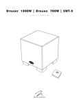
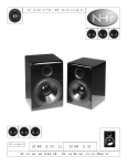
DYNA MO™ 1
ooow I
DYNA MO™ 700W
user's
manu al
MARTIN LOGAN
I
SWT-1
IMPORTANT SAFETY INSTRUCTIONS
Read these instructions .
12
Use only with the cart, stand, tripod, bracket, o r table specified by the manufacturer,
Keep these instructions.
or sold with th e apparatus . When a cart
3
Heed all warnings.
apparatus com bination to avoid injury from
4
Follow all instructions.
5
Do not use this apparatus near water.
6
Clean on ly w ith dry cloth.
7
Do not block any venti lation open ings Install in accordance with the
2
is used use caution when moving the cart/
tip-over.
13. Unplug thi s apparatus during lightning storms or w hen unused for
long periods of time.
14. Refer all servicing to qualified service personnel. Servicing is required
w hen the apparatus has been damaged in any way, such as powersupply cord or plug is damaged, liquid has been spilled or ob1ects
have fallen into the apparatus, the apparatus has been exposed to rain
manufacturer's instructions.
or moisture, does not operate normally, or has been d ropped .
Do not install near any heat sources such as rad iators, heat registers,
8
stoves, or other apparatus (inlcuding amplifiers) that produce heat.
Do not defeat the safety purpose of the polarized or grounding-type
plug. A polarized plug has two blades with one wider tha n the other.
9
A grounding type plug has two blades and a third grounding prong.
The wide blade or the third prong are provided for your safety If the
15. WARNING: To reduce the risk of fi re or electric shock, th is apparatus should not be exposed to ra in or moisture and ob jects filled w ith
liquids, such as vases, should not be placed on th is appa ratus .
16. To com pletely disconnect this equipment from the mai ns, disconnect
the power supply cord plug from the receptacle.
provided plug does not fit into you r outlet, consult an electrician for
replacement of the obsolete o utlet.
17. The mains plug of the power supply cord shall remain readily operable.
·10
Protect the power cord from being walked on or pinched particularly at plugs, convenience receptacles, and the poi nt where they exit
from the apparatus.
18
Do not expose this equipment to d ripping or splash ing and ensure
that no ob jects filled with liquids, such as vases, are placed o n the
equipment.
11
O nly use attachments/accessories specified by the manufactu rer.
In accordance w ith the European Union WEEE (Waste
-
Electrical and Electronic Equipment) directive effective
August 1 3, 2005 , we w ould like to notify you that this
prod uct may contain regulated materials w hich upon
cost to you. To find your local distributor please contact the dealer from
whom you purchased this product, email info@martinlogan com or visit
the distributor locator at www.martinlogan.com.
disposa l, according to the W EEE directive, require special reuse and
Please note, on ly this product itself fa lls under the W EEE directive.
recycling processing .
When disposing of packaging a nd other related sh ipping materials we
encourage you to recycle these items through the normal channels.
For this reason Mortinlogan has arranged w ith our d istributors in
European Union member nations to collect and recycle this product ot no
The lightning bolt flash with arrowhead symbol, within
The exclama tion point within an equilateral triangle is
an equilateral tria ng le, is intended to alert the user to
the presence of uninsulated "dangerous voltage" w ithin
intended to alert the user to the presence
operating and maintena nce (servicing) instructions in
the product's enclosure that may be of sufficient mag-
the literature accompanying the appliance.
nitude to constitute a risk of electric shock.
2
of important
Important Safety Instructions • •••••••••••
Contents • • • • • • • • • • • • • • • • • • • • • • • • • • •
Packaging • • • • • • • • • • • • • • . . • • • • • • • • • •
Introduction and Installation in Brief• ••••••
2
3
4
6
Room Acoustics . . . . . . . . . . . . . . . . . . . . . 13
Your Room
Terminology
Solid Footing
Home Theater • • • • . . • • • • . . • . • • • • . • • • 14
FAQ & Troubleshooting • • • • • • . • • • • . • • • 15
Introduction
Installation in Brief
About the Controls • • • • • • • • • • • • • • • • • • • • 7
Connections and Control Settings • • • • • • • • • 8
Frequently Asked Questions
Troubleshooting
Before Connecting the Dynamo
2-Channel Mode
Multi-Channei/LFE Mode .... .. .. . .. . .. . . . .. 9
AC Power Connection . . . . . . . . . . . . . . . . . . . . 10
Replacing the Fuse
Break-In
Optional Wireless Connection
Specifications . . . . . . . . . . . . . . . . . . . . . . . 16
Placement • • • • • • • • • • • • • • • • • • • • • • • • • 11
SWT-2 Dimensional Drawings
18
Dynamo 1OOOW Dimensional Drawings .
Dymamo 7 00W Dimensio na l Drawings . . . . ... 19
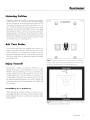
Listening Position
Ask Your Dealer
Enjoy Yourself
Installing in a Cabinet
Changing Woofer Orientation.
Dynamo 1OOOW Specifications
Dynamo 700W Specificaitons
General Information • • • • • . • • . • • • • • • • • 17
Warranty and Registration
Service
Dimensional Drawings • • • . . • • . • • • • . • . • 17
12
Serial N umbers
Record your serial numbers here for easy reference. You will need this information when filling out your warranty registration. Your serial number is located
near the boffom of the backplate and on the shipping container.
CE
This device complies with part l 5
of the FCC Rules. Operation is
Dynamo 1OOOW
Dynamo 700W
sub ject to the fo llow ing two cond itio ns: ( l) Thi s d evice may not
ca use harmful interference, a nd
Tested to Comply
w ith FCC Standards
FO R HOME OR O FFICE USE
(2 ) this device mu st accept a ny
interference rece ived , includ ing
interference that may cause undesired operation.
&
WARNING!
• Hazardous voltages exist inside-do not
remove cover.
• Refer servici ng to a qualified techn ician .
• To prevent fire or shock hazard , do not
expose this module to moisture.
• Unplug subwoofer should any abnormal
conditions occu r.
WARNING! Do not use your Dynamo 1OOOW or Dynamo 700W subwoofers or SWT-2 transmitter outside of the
.country of original sale-voltage requirements vary by country. Improper voltage can cause damage that will be potentially expensive to repair. The Dynamo 1OOOW or Dynamo 700W subwoofers and SWT-2 transmitter ore shipped to
authorized Mortinlogan distributors with the correct power supply for use in the country of intended sale. A list of authorized distributors can be accessed at www.martinlogan.com or by emailing info@martinlogan.
3
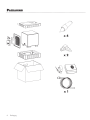
PACKAGING
x4
x2
xl
4
Packaging
Thank you-the Mortinlogan owner,
for loving w hat we do,
and
making it possible for us to do what w e love.
5
INTRODUCTION AND INSTALLATION IN BRIEF
Introduction
Congratulations! You have invested in one of the
world's premier subwoofers.
The Martinlo gan Dy nam o 1 OOOW and 700W
subwoo fe rs represe nt th e exte nsio n o f o n inte nsive,
ded icated team research program directed toward establishing a world class line of reference subwoofers using
leading-edge technology, without co mpromising dura bility, reliability, craftsmanship or aesthetics.
Th ese subwoofers use hig h-excursio n dri vers to ach ieve
d eep, tight, well-defined bass. A propri etary a mplifier is
used to drive the output stage with precision and extremely
hig h efficiency . Low-pass filtering and phase control have
been designed to make integrating the Dynamo 1OOOW
a nd Dyna mo 700W subw oofe rs w ith M arti nlogo n a nd
no n-Martinloga n prod ucts both seamless and simple .
The materi a ls in your new subwoofer are of the hi g hest
quality and w ill provide years of enduring enjoyment a nd
d eepening respect. The cabinet is constructed fro m the
finest composite material for acoustica l integ ri ty and is fi nished with an a ttractive custom coating.
Th is User's Manual will explai n in deta il the operation of
your subwoofer and the philosophy a pplied to its design.
A clear understa nding w ill insure that you obtain ma ximum performance and pleasure from thi s most exacting
subwoofer.
Installation in Brief
We know that you are eager to hear your new subwoofer,
so this section is provided to allow fast a nd easy set up. O nce
you have it operational, please take the time to read, in depth,
the rest of the information in this manua l. It w ill give you perspective on how to attain the g reatest possible performa nce
from this most exacting subwaafer system.
If yo u experience a ny d ifficulti es in setup o r o perat io n
of th e subwoo fer, plea se refer to th e Pl a cement, Roo m
Acoustics a nd Connections a nd Control Settings sectio ns.
6
Introduction and Insta lla tion in Brief
Should you encounter a persistent pro blem that cannot
be resolved, please contact your authori zed M artinlogan
dealer. They will provide you with the a ppropriate technical analysis to alleviate the situation.
Step 1: Unpacking
Remove your new subwoofer from its packi ng .
Step 2: Placement
Ideally, place the subwoofer in a corner near the front of the
room . This is a good place to start. Please see the Placement
section (page 1 1) of this manual for more details.
Step 3: Signal Connection
The Dyna mo l OOOW a nd Dynamo 700W subwoofers
are provi ded w ith the SW T-2 subwoofer w ireless transmitter. We recommend using a physical w ire con nection
if possible. However, if id ea l subwoofer placement is a
c ha llenge the SW T-2 w ill provi d e a sea mless wireless
co nnection with an extremely detailed and articulate bass
performance.
Use the best cables you can . High qua lity ca bles, ava ila ble
fro m your specia lty dea ler, are reco mmend ed a nd w ill
give you superior perfo rmance .
Attach your preamplifier/ processor outputs th rough cables
to the si gnal input area located on the subwoofer's rear
pa nel. Plea se see the Connectio ns a nd Contro l Settings
sectio n (pages 8- l 0 ) of this ma nual for more details.
Step 4: Power Connection (AC) (see warning)
Make su re the level kn o b is set at 'M in' . Plu g the
subw oofer into a wa ll ou tl et. Review th e AC Power
Connectio n sec ti on (page l 0 ) of thi s ma nua l fo r mo re
deta ils.
Step 5: Setting the Controls
Set the leve l kn ob to a med ium vol um e pos ition ( 1 2
o 'clock) . Set the power sw itch to 'Auto On '.
Step 6: Listen and Enioy
N ow, you may ad just your system a nd en joy!
ABOUT THE CONTROLS
Level
Low Pass Filter (Hz)
Line Level
Input
Crossover
Phase
ao
Min
Max
Bypass
(LFE In)
180°©
90° ©
Variable
(L & R In)
Left In
35Hz
120Hz
~
(LFE In)
Right In
®®
Figure 1. Dynamo l OOOW and Dynamo 700W controls.
Level Knob
Setting the level too hig h w ill cause the bass to seem bloated and is the sing le most common cause of bad sounding
subw oofers. A rule of thumb is that the subwoofer should
not draw attention to itself, but should simply make the systems low end seem more extended and accurate.
Phase Control Switch
The phase con trol is entirely dependent on the size a nd
configuration of your listening enviro nment, the placement
of the unit, and your seating arrangement. Due to the w ay
bass sound w aves develo p in d ifferent rooms, there is
no rul e of thum b for settin g phase. Fo r insta nce, if you r
room has a peak at the subwoofer crossover area, you
may w ish to set the phase so the actual acoustic outputs
of the subwoofer a nd ma in spea kers are o ut of phase.
Experiment, try different settings a nd be patient.
sor handles the bass management. When connected in
2-channel mode via its left/ right input, the low-pass fil ter
is active.
As a general rule the low pass filter should be set equal
to approximately 7 0 % of your speaker's lowest frequency
response . Remember, this is a general rule. We advise
that once you try the recommended setting using the formula above, you should try the surroundi ng settings to see
w hich sounds best.
Wireless Sync BuHon and Status LED (not shown above)
The wireless sync button is used to establish con nection to
the SWT-2 M arti nLoga n Subwoofer W ireless Transmitter.
The Wireless status LED indicates the current status of the
w ireless connection (see page l 0 for further details).
Status LED (not show n above)
Crossover
When the subwoofer is connected in multi-channel mode
(via LFE), the crossover switch should be set to 'Bypass (LFE
In)' so that the low pass filter is not active and your processor ha nd les the bass management.
W hen connected in 2-channel mode (via left/ rig ht input),
the crossover switch should be set to 'Variable (L& R In)' so
that the low-pass filter is active.
Low Pass Filter Knob
Wh en the sta tu s LED (loca ted o n the bac k of th e
subwoofer) is blue, the subwoofer is on. When the status
LED is red the subwoofer is in standby mode.
Master Power Switch (not shown above)
Located on the back pa nel of the subwoofer, the Master
Power swi tch must be set to 'Au to O n' for the subwoofer
to ope rate . When set to 'Auto O n' the su bwoofer w ill
a utomatica lly enter a power saving mode when no a udio
signal is detected . The subwoofer w ill automatica lly come
o ut of power saving mode when a signal is detected .
When the subwoofer is connected in multi-chan nel mode
(via LFE), the low pass filter is not active and your proces-
About the C o ntrols
7
CONNECTIONS AND CONTROL 5EniNGS
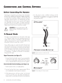
Before Connecting the Dynamo
Martinlogan's engineering and design team developed
the Dynamo 1OOOW and Dynamo 700W subwoofers
for easy setup and system integratio n. Before beginn ing
to connect your subwoofer, please review the con trols
discussed in the last sectio n. An understanding of these
will help speed you along as you connect and integrate
your subwoofer w ith your system. All signal connections
are done on the rear connections panel of the subw ooferMake certain that all of your connections are tight.
4 Try the phase control in different settings until the
best b lending is obta ined. If you ore a ugmenting
Martin logan loudspea kers, we suggest you start with
the phase set at 90°.
DYNAMO™
Line Level
Input
WARNING! Turn your subwoofer to 'Off'
Left In
(LFEIn)
Right In
before making or breaking any signal connections!
2-Channel Mode
This setup is recommended if yo ur su bw oofer w ill be used
in a 2-c hanne l syste m with ma in speake rs play ing full
range. When a signal is connected via left/right inputs
and the crossover switch is set to 'Variable (L&R In), the
subwoofer's internal low pass filter is active.
If yo u w ill be using your system fo r both 2-c ha nnel and
multi-channe l li stening we recommend conn ecting the
subwoofer as recommended in 'Multi-Channei/LFE M ode'
on the next page. Some modern receivers and processors
allow use rs to route left and right c hannel low-frequ ency info rm ation, in ad dition to discrete LF E info rmation,
through the LFE output.
PREAMPLIFIER/RECEIVER
Figure 2. Sig na l connectio n for 2-c han nel mode.
Signal Connection {see figure 2):
Connect the left and rig ht outputs of yo ur preamplifier
to the left and rig ht inputs using q uality RCA interco nnects. If your prea mplifier only ha s one set of outputs
you may need to obta in Y adapters from your dea ler.
Recommended Control SeHings {see figure 3):
Low Pass Filter (Hz)
Level
@
Mi n
Max
Crossover
Phase
,ag:At
\\o.V'
goo
Bypass
(~)
\\oV ~
Variable
(l & R In)
Set the crossover switch to 'Variable (L&R In)' .
DYNAMOTM
2 Set the 'Low Pass Filter' knob to approximately 7 0 % of
your loudspeakers lowest frequency response .
3 W hile playing music w ith bass co ntent, turn the level
co ntro l up until th e music has deep extend ed bass,
being careful to avoid levels that become overwhelming.
8
C onnections and Contro l Settings
Figure 3. Contro l setting s fo r 2-channe l mod e.
©)
35Hz · 120Hz
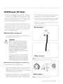
Multi-Channei/LFE Mode
This setup is recommended if your subwoofer will be used
in a dedicated home theater or multi-channel system. When
a signal is connected to the subwoofer's LFE input, and the
crossover switch is set to 'Bypass (LFE In)' the internal low pass
filter is not active. By following this setup, you will allow your
processor to handle most of the bass management.
If you w ill be using your system for both 2-channel and
multi-channel listening we recommend using this setup
and connection method. Some modern receivers and
processors allow users to route left and right c han nel
low-frequency information, in addition to discrete LFE information, through the LFE output.
Pass: 24dB. The optimal setting for these options may vary
depending on your room and listening preferences.
4 Adjust the phase control until ideal blending is obtained. If
you hear no discernible d ifference leave the phase at 0°
5 Fo llow the instructions in your processor manual to finetune the subwoofer level
DYNAMO™
Line Level
Input
Signal Connection (see figure 4):
(LFE In)
Right In
Left In
Connect the LFE output of the p rocessor to the LFE input
using a quality RCA interconnect.
WARNING!
Based on the pe~ormance of most processors, it is recommended that Martinlogan
center and effects type speakers not be run
in large, wide, or full range mode. Doing
so may potentially damage the speaker if
the processor attempts to drive the speaker
beyond its rated frequency range. This
warning also applies to products from other
manufacturers.
It is recommended to run center and effects
type speakers in limited or narrow mode.
Some processors have an option to route the LFE
channel to your main and/or surround speakers.
We recommend that you do not use this option.
~ ~
LFE Out
PROCESSOR
Figure 4. Signal conneclion for multi-channel mode.
Recommended Control SeHings (see figure 5):
Level
Set the crossover switch to 'Bypass (LFE In)'.
2 Use the bass management section of your processor's
speaker level setup option to set the subwoofer level at an
appropriate level. Follow the instructions in your processor
manual to fine-tune the subwoofer level.
3 If your processor offers the option to setup crossovers fo r a
subwoofer, we recommend that you start w ith the following
settings- C rossover: 70Hz, High-Pass: 1 2dB, and Low-
@
Min
Max
Crossover
Phase
Bypass
(LFE In)
1~~:©t © ..
Variable
(L & R In)
DYNAMO™
Figure 5. Control settings for multi-channel mode.
Connections a nd Control Settings
9
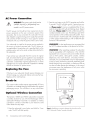
AC Power Connection
WARNING! The
power cord should not be
installed, removed, or leh detached from
the subwoofer while the other end is connected to an AC power source.
The IEC power cord should be firm ly inserted into the AC
power receptacle on the rear connection panel of the
subwoofer, then to any convenient AC wall outlet. The sub
also integrates a signal sensing pow er supply that automatically switches off after sensing no music signal for several
minutes (this will occur when the power switch is set to 'Auto').
Your subwoofer is wired for the pow er service supplied in
the country of original consumer sale. The AC pow er rating applicable to a particular unit is specified both on the
pocking carton and on the serial number plate attached to
the subwoofer.
If you remove your subwoofer from the country of o rig inal
sole, be certain that AC power supplied in any subsequent
location is suitable before connecting and operating the
subwoofer. Substa ntially impaired performance or severe
damage may occur to the subwoofer if operation is attempted from an incorrect AC pow er source .
Replacing the Fuse
2 Press the sync button on the SWT-2 transmitter and hold for
3 seconds. The LED will blink quickly . If pairing has completed successfully both LEDs will stop blinking and remain
on. Please note: If a link is not established aher 30 seco nds this transmitter's LED w ill start blinking slowly. Repeat
both steps. Please note: The LED will blink slowly if the
w ireless transmitter is not in use. This blinking is part of the
normal operation of the w ireless subwoofer system. If you
should choose to mask this LED with a small piece of tope
or other opaque material doing so will not affect the performance of the subwoofer.
WARNING! For best performance w e recommend that
the SWT-2 wireless transmitter not be placed on the floor.
WARNING! When operating w irelessly this subwoofer
may be suscepti ble to RF interference in the 2 .4G Hz
ba ndwidth fro m microwave ovens a nd w ireless devices
such as WiFi systems, video game consoles, cordless
telephones , blue tooth devices, and baby monitors.
G enerally, this issue (intermittent sound or slight popping
no ises) is easily resolved by physica lly separating problematic devices from one another-a distance as little as
two feet will ohen alleviate the interference. In the case of
microwave ovens, the interference w ill only occur when
the microwave is operating.
If the fuse in your subwoofer sho uld require chang ing , turn
off a nd unplug your subwoofer befo re removing the fuse.
Replace w ith a matching fuse .
Break-In
O ur custom made woofers require approximately 50 hours
of break-in at moderate listening levels before their opti mal
performa nce occurs. This will fa cto r in on any critical listening and judgment.
Optional Wireless Connection
The Dynamo l OOOW and 7 00W subwoofers incorporate
a wireless receiver for use with the M artinLoga n SWT-2
Subwoofer Wireless Tra nsmitter. To esta blish a wi reless
connectio n, co nnect a tra nsmitter to your electro nics and
follow these two easy steps.
1 . Press the subw oofer' s sync butto n and hold for 3 seconds. The LED w ill blink quickly .
l0
Connections a nd Control Settings
Figure 6. Establishing a connection between the subwoofer and the
SWT-2 Subwoofer W ireless Tra nsmitter (included (.
PLACEMENT
Listening Position
Generally, subwoofers have the most output when placed
in the corner of a room. However, this can also exaggerate the subwoofers output making blending difficult. We
recommend starting by placing the subwoofer in a corner. If, after the full range of tuning techniques have been
employed, the subwoofer sounds like it has too much upper
bass energy try pulling it away from the wall, toward the
listening position. Th is will lessen the reinforcement of these
problematic frequencies from the wall and likely smooth out
the response. Repeat the tuning techniques with the woofer
controls after you move it (see figure 7).
D
§
D
Ask Your Dealer
Your Martinlogan dealer can suggest many options for
optima l subwoofer placement. They also have many tools
at their disposa l, such as experience, familiarity with the
associated equipment, and even sound analysis equipment
w hich may make the task of determining optimal subwoofer
placement easier.
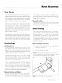
Figure 7. Dynamo subwoofers as the LFE (effects) channels, Martinlogon
Enioy Yourself
The Dynamo l OOOW and Dynamo 7 00W are very
refined subwoofers and will benefi t from care in setup.
With the above placement tips in mind you w ill find , over
months of listening, that small changes can resu lt in measurable differences. As you live with your subwoofer, do
not be afra id to experiment w ith position ing until you find
the optima l relationsh ip between your room, settings and
subwoofer that gives you the best results. Your efforts wi ll
be rewarded.
speakers as front, center, and surround (effects) channels. Note the corner
placement of the subwoofers at the front of the listening room.
'
'
-
.... -
-
-
-
-
-
-
-. -
-
-
-
-
- ,- J
I
I
I
I
I
I
I
II
, '- - - -1
L
\\
\\
\\
'~,
,,
·-~
- - 11
,~'
£-------------~ I
'
'
' -_-_-_-_-_-_r'
•,-_
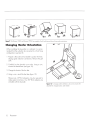
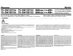
Installing in a Cabinet
When placing the subwoofer inside of a cabinet it is recommended that there be o minimum of three inches of open
space between the cabinet and the front and bock sides
(see figure 8 ).
3-inches
Figure 8. Placing the subwoofer in a cabinet requires a mini mum of th ree
inches of open space on the front and back.
Placement
l l
Figure 9. The Dynamo l OOOW and Dynamo 700W are capable of both front-firing and down-firing woofer orientations.
Changing Woofer Orientation
When installing the subwoofer in a cabinet it is recommended that the subwoofer be converted to a front firing
configuration. (see figure 9).
Prepare a flat surface with a blanket to protect the finish.
Unplug signal and power connections. Remove the grill
cloth.
2 Carefully lay the subwoofer on its side. Using a coin,
unscrew the attached feet. (see figure l 0).
3 Change the location of the four feet.
4 Using a coin, reinstall the feet (see figure l 0).
Please note, 90° RCA adaptors may be required to
make signal connections. Two 90° RCA adaptors are
included with the subwoofer.
Figure 10. To change woofer orientation, use a coin to unscrew the
attached feet, change location, and reinstall.
l2
Placement
ROOM ACOUSTICS
Your Room
This is an area that requires both a little background to
understand and some time and experimentation to a ttain
the best performance from your system. Your room is actually a component and an important part of your system.
This component is a Iorge variable and can dramatically
add to or subtract from a great sonic experience.
All sound is composed of waves. Each frequency has its
own wove size, with the lower, or boss frequencies literally encompassing from l 0 feet to as much as 40 feet. Your
roo m pa rtic ipates in this wave experience like a sw imming pool with waves reflecting and becoming enhanced
depending on the size and shape of the room and the
types of surfaces in the room.
Remember that your audio system can actually generate all
of the information required to recreate a sonic event in time,
space, and tonal balance. Acoustically, the role of on ideal
room w ould be to neither delete nor contribute to that information. However, nearly every room does to some degree.
Terminology
Standing Waves
Sound coming from a speaker bounces around in a room
until a pattern emerges-this is called a standing w ove.
Typically, this is o nly a pro blem w ith frequen c ies below
l OOHz. When this ha ppens different parts of yo ur room
experience either an excess or a lack of boss.
Some peo ple believe that having a room without para llel
walls will eliminate this effect. The truth is that non-parallel
walls only generate different standing wove patterns tha n
those that occur in recta ng ular rooms.
with the music, and may contribute in a nega tive way to
the sound. Ringing , boom iness, and even brightness can
occur simply because surfaces and objects are "singing
along" w ith your speakers.
Resonant Cavities
Small alcoves or closet type areas in your room can be
chambers that creole their own "standing w aves" and can
drum their own "one note" sounds.
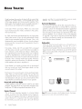
Solid Footing
After liv ing and exper imenting with yo ur subwoofer,
you may want to use ETC™ (Energy Tran sfer Coupler)
Spikes (see figure l l ). W ith the use o f these spikes,
the subwoofer will become more firm ly planted o n the
floor a nd , co nsequently , bass will tighten. It is best not
to implement the spikes, however, until you are secure in
the positioning, as the spikes con damage the floor if the
subwoofer is moved.
Spike Installation Instructions:
Carefully lay the subwoofer on its side to gain access
to the bottom of the feet.
2 Firmly press the spikes into the feet.
Caution: Make sure yo ur hand s a nd any c a bling are
clear of the spikes . Do not slide the subw oofer as spikes
are sharp and can damage your floor or carpet.
Usually, you can exc ite most o f the standin g waves in
a roo m by putting the subwoofer in a corn er. Li ste ning
pos ition determines w hich standing w aves yo u will experien ce. For instance, if yo u sit in a corner you will hear
most of the stand ing waves . This can be on overpow ering
experien ce . Sitting next to a wall con also intensify the
levels of the sta nding w aves tha t are experienced.
Resonant Surfaces and Obiects
A ll of the surfaces a nd objects in your room ore subject to
the frequencies generated by your system. Much like a n
instrument, they w ill vibrate and "carry on" in syncopation
Figure 11. To insta ll the spikes, press them into the feet.
Room Acoustics
l3
HOME THEATER
It had long been the practice of stereo buffs to connect their
television to a stereo system. The advantage was the use
of the larger speakers and more powerful amplifier of the
stereo system. Even though the sound was greatly improved, it
was still mono and limited by the broadcast signal.
In the late 1970's and early 1980's two new home
movie formats became widely available to the public:
VCR and laser disc.
By 1985, both formats had developed into very high quality
audio/video sources. In fact, the sonic performance of some
video formats exceeded audio-only formats. Now, with
theater-quality sound available at home, the only element
missing was the "surround sound" presentation found in
movie houses.
Fortunately, Dolby and DTS encoded DVD's emerged
with the same surround sound information encoded on
home releases as the theatrical release. Additionally,
new high-resolution home-viewing formats such as Blu-ray
as well as high-definition content provided via cable or
satellite have evolved which include multi-channel encoded audio that is virtually master tape quality. All that is
required to retrieve this information is a decoder and additional speakers and amps to reproduce it.
speaker, and that it is recommended for use as a center
speaker. This is not the place to cut corners.
Surround Speakers
We recommend (along with the film industry) that the surround speakers play down to at least 80 Hz. Surround
speakers contain the information that makes it appear that
planes are flying over your head. Some may suggest that
this is the place to save money and purchase small, inexpensive speakers. If you choose to do so, be prepared
to upgrade in the future as discrete multi-channel digital
encoding is proliferating rapidly and the demands on surround speakers have increased.
Subwoofer
With any good surround system you will need one or
more high-quality subwoofers (the .1 in a 5.1, 6.1, or 7.1
channel surround system). Most movie soundtracks contain
large amounts of bass information as part of the special
effects. Good subwoofers will provide a foundation for the
rest of the system.
D
D
Home theater is a complex purchase and we recommend
that you consult your local Martinlogan dealer, as they
are well versed in this subject.
Each piece of a surround system can be purchased separately. Take your time and buy quality. No one has ever
complained that the movie was too real. The following list
and descriptions will give you only a brief outline of the
responsibilities and demands placed on each speaker.
Front Left and Front Right
If these speakers will be the same two used for your stereo
playback, they should be of very high quality and able to play
loudly (over 102 dB) and reproduce bass below 80Hz.
Center Channel
This is the most important speaker in a home theater
system, as almost all of the dialogue and a large portion of the front speaker information is reproduced by the
center channel. It is important that the center speaker
be extremely accurate and mate well with the front
14
Home Theater
Figure 12. Dynamo subwoofers as the LFE (effects) channels, Martinlogon
speakers as front, center, and surround (effects) channels
FAQ &
TROUBLESHOOTING
Frequently Asked Questions
Troubleshooting
How do I clean my subwoofer?
No Output
Use a dust free cloth or a soh brush to clean your subwoofer.
We recommend a specialty cloth (a vailable through the
Xtatic shop at www.martinlogan.com) that cleans better than
anything else we have tried.
Can I turn oH the blinking light on the back of my sub?
The LED will blink slowly if the w ireless transmitter is not in
use. This blinking is part of the normal operation of the w ireless subwoofer system. If you should choose to mask this LED
with a sma ll piece of tape or other opaque material do ing so
w ill not affect the performance of the subwoofer.
Is it safe to set things on my subwoofer?
While your subwoofer is designed w ith a durable, stainresistant surface, we advise you not to set anything on your
subwoofer-especially conta iners hold ing liq uids.
Is there likely to be any interaction between
my subwoofer and the television in my Audio/
Video system?
Yes . The subwoofer does n't use a shielded driver. We
reco mm end 3 feet between the subwoofe r a nd vid eo
components tha t are suscepti b le to magnetic fi e lds..
Plasma, LCD, a nd LED television are not suscepti ble to
mag netic interference.
Is there likely to be any interaction between my
subwoofer and other electrical devices in my house?
Yes . W hen opera ting w irelessly this subwoofer may be susceptible to RF interference in the 2.4GHz bandwidth from
microwave ovens and w ireless devices such as W iFi systems, video game consoles, cordless telephones, blue tooth
devices, and baby monitors. Generally, this issue (intermittent sound or slight popping no ises) is easily resolved by
physical ly separating problematic devices from one a nother-a d istance as little as two feet w ill often a llevia te the
interference. In the case of microwave ovens, the interference w ill only occur w hen the microwave is operating.
Will my electric bill go 'sky high' by leaving my
subwoofer plugged in all the time?
No . When the powe r switc h is set to 'Au to O n' the
subwoofer w ill d raw about 15 watts w hen id le a nd only
l watts in standby mode.
• Check that all your system components are tu rned on.
• Check that the master power switch adjacent to the AC
receptacle is set to 'Auto O n' .
• C heck your w ires a nd connectio ns.
• C heck all interconnecting ca bles.
• Make sure the level control is not turned down .
• Turn off and unplug the su bwoofer and check the fuse
near the AC power cord receptacle on the bock. If the
fuse has blown , replace the bad fuse with o matching
fuse.
• If the problem persists, contact your dealer.
Muddy Bass
• Check placement. Try moving the subwoofer closer to
the front and side wa lls.
• C heck the type of feet that are bei ng used . Try insta lling
the ETC spikes .
• Decrease the level.
• Check your processor setup .
• If the problem persists, contact yo ur dealer.
Hums or Unusual Sounds
• Turn the subwoofer off, unplug a ll signal inputs, turn the
subwoofer bock o n and tu rn up the level. If the problem
di sa ppears, the hum is originating elsewhere in your
system.
• Connect the subwoofer's AC connection to the sa me AC
circuit as the pre amp .
• If ope ra ting in w ireless mode, move the subwoofer
away from microwave ovens a nd / or any devices tha t
use wireless technology.
• If the problem persists, contact your dealer.
Intermittent Output With Wireless
• M a ke sure that no oth er wireless devices are w ithin 2
feet of the SWT-2 tra nsmitter.
• C heck placement and ma ke sure the SWT-2 wireless
tra nsm itter is at least 1 foot off of the g ro und.
• M ove the SWT-2 transm itter and sub closer together.
• Remove ba rriers fro m between the devices . A lthough
the SWT-2 uses on RF sig na l, it may not pe netrate
some wa lls or cabinets.
Should I unplug my subwoofer during a thunderstorm?
Yes, or before It's a good idea to discon nect a ll of your
a ud io/video components d uring stormy weather.
Frequently Asked Q uestions & Troubleshooting
15
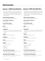
SPECIFICATIONS
Dynamo 1 OOOW Specifications
The Dynamo 1OOOW subwoofer system con sists of a
single woofer for high SPL output with minimal distortion.
The equalization used is specifical ly designed to counteract the response of the woofers sealed box response. This
equa liza tion leads to minima l group delay and proper
transient response.
Dynamo 700W Specifications
The Dynamo 700W subwoofer system consists of a single
woofer for high SPL output w ith minima l distortion. The
equa lization used is specifically designed to cou nteract
the response of the woofers sea led box response. This
equalization leads to minimal group delay and proper
transient response.
System Frequency Response
22- 200 Hz ± 3 dB. Anechoic in LFE mode.
System Frequency Response
24-200 Hz± 3 dB. Anechoic in LFE mode.
Low Pass Filter Frequencies
35Hz- 120Hz
Low Pass Filter Frequencies
35Hz- 120Hz
Low Pass Filter Switch
Bypass (LFE In), Variable (L&R In)
Low Pass Filter Switch
Bypass (LFE In), Variable (L&R In)
Phase
0 °, 90°, 180°
Phase
0°, 90°' 180°
Components
12 " (30.5cm) high-excursion, polypropylene cone with
extended throw driver assembly; sealed non-resonant cabinet design
Components
10 " (25 .4cm ) high-excursion, polypropylene co ne with
extended throw driver assembly; sealed non-resonant cabinet design
Amplifier
Amplifier
500 watts RMS ( 1000 watts peak)
300 watts RMS (600 watts pea k)
Impedance
Left & Right/ LFE RCA- 20,000 O hms
Impedance
Left & Right/LFE RCA - 20,000 O hms
Inputs
Left & Right/ LFE RCA Li ne Level
Inputs
Left & Right/ LFE RCA Line Level
Weight
34 lbs. each (15 4 kg)
Weight
26.5 lbs . each ( 12 kg)
Mains Power Draw
Standby: 1W
Idle: 15W
Max: 650W
Mains Power Draw
Standby: 1W
Idle: 15W
M ax: 400W
Size (Front-Firing Orientation)
13.69 inches W x 14 .35 inches D x 15.46 inches H
(34 Scm W x 36 .4cm D x 39 .3cm H)
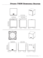
Size (Front-Firing Orientation)
11.69 inches W x 12 .3 1 inches D x 13.47 inches H
(29 .7cm W x 3 1.3cm D x 34. 2cm H)
Size (Down-Firing Orientation)
13.69 inches W x 14 .59 inches D x 14 .54 inches H
(34 .8cm W x 37. 1em D x 36.93cm H)
Size (Down-Firing Orientation)
11.69 inches W x 12.53 inches D x 12.54 inches H
(29.7cm W x 3 1.8cm D x 3 1.9cm H)
16
Specifications
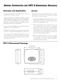
GENERAL INFORMATION AND
5WT·2
Warranty and Registration
DIMENSIONAL DRAWINGS
Service
Your Dynamo subwoofer is provided with an automatic
Limited 90 Day Warranty coverage.
Should you be using your Martinlogan product in a country
other than the one in which it was origina lly purchased,
we ask that you note the fol lowing:
You have the option, at no additional charge, to receive
Limited 3-Year Warranty coverage. To obtain the Limited
3-Year Warranty coverage you need to complete a nd
return the Certificate of Registration , included with your
subwoofer, and p rovide a copy of your dealer receipt, to
Martinlogan within 30 days of purchase.
The appointed Martinlogan distributor for any given
country is responsible for warra nty servicing only on units
distributed by or through it in that country in accordance with its applicable w arranty.
2 Should a Martinlogan product require servicing in a
country other than the one in which it w as originally
purchased, the end user may seek to have repairs perfo rmed by the nearest Martinlogan d istributor, subject
to that distributor's local servicing policies, but all cost
of repa irs (parts, labor, transportation) must be born by
the owner of the Martinlogan product.
For your convenience Martinloga n also offers online warranty
registration at www.martinlogan.com .
Martinlogan may not honor warranty service claims unless
we have a completed Warranty Reg istration card on file!
If you did not receive a Certificate of Registration with your
new subwoofer you cannot be assured of having received
a new unit. If this is the case, please contact your authorized Martinlogan dealer.
3 If, a~er owning your subwoofer for six months, you relocate
to a country other than the one in wh ich you purchased
your subwoofer, your warranty may be tra nsferable.
Contact Martinlogan for details.
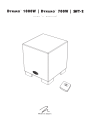
SWI-2 Dimensional Drawings
3.64" (9 .3cml
3,64po (9,3cml
w
0
0
-o
OJ
0
~
-o
w
()
3
3
D
(II [@\@
<@~-----~~ ~
3-
G eneral Information a nd SWT-2 Dimensional Drawings
17
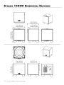
DYNAMO
1 000W DIMENSIONAL DRAWINGS
13.69" (34.8cm)
13 69po (34 Scm)
'
'
J
n11111111n
L.J
13.69" (34.8cm)
13,69po (34,8cm)
14.35" (36.4cm)
14 35po (36 4cm)
'
'
12.94" (32.9cm)
12,94po (32,9cm)
LJ
II...._..J
14.59" (37.1 em)
14,59po (37, 1em)
I
IL_j
l8
Dynamo l OOOW Dimensional Drawings
DYNAMO
700W
DIMENSIONAL DRAWINGS
12.31" (31.3cm)
12 , 31 po (31 ,3 em )
11.69" (29.7cm)
11 ,69po (29,7cm)
LJ
j
....
11.69" (29.7cm)
11 ,69po (29,7cm)
10.94" (27.8cm)
10, 94po (27,8cm)
LJ
VL_J
12.53 " (31 .8cm)
12,53po (31 ,Scm)
~
~
j
LJ
II
LJ
u...,....._._JIII
LJ
Dynamo 7 00W Dimensional Drawi ngs
19
WARNING!
Do not use your Dynamo 1OOOW or Dynamo 700W subwoofers or SWT-2 transmitter outside of
the country of original sale-voltage requirements vary by country. Improper voltage can cause damage that will
be potentially expensive to repair. The Dynamo 1OOOW or Dyna mo 700W subwoofers and SWT-2 are shipped
to authorized Martinlogan distributors with the correct power supply for use in the country of intended sale. A list
of authorized distributors can be accessed at www.martinlogan .com or by emailing info@martinlogan.
M A RTIN LOGA N ®
Law r e n ce, Ka n sas, U SA
t el 7857 4 9 0133
fa x
7 85 . 7 49 . 5320
©20 1 I Marlinlogon Al l rig hts reserved
w w w .mor finloga n . co m
Rev # l 02 1 7 1
NO POSTAGE
NECESSARY IF
MAILED IN THE
UNITED STATES
MARTIN LOGAN®
BUSINESS REPLY MAIL
FIRST-CLASS MAIL
PERMIT NO. 66 LAWRENCE, KS
POSTAGE WILL BE PAID BY ADDRESSEE
MARTIN LOGAN
2101 DELAWARE ST
LAWRENCE, KS 66046-9702
USA
1.11 ••• 11 •• 11 •••• 1•• 1.11 •• 1.1 •• 1••• 111 ••••• 1.111 ••• 1
To receive a Limited Five Year Warranty (Three Year
Warranty for subwoofers), free of charge, you must
return this registration card within 30 days from
date of delivery. For your convenience Martinlogan offers full warranty details and online warranty
registration at www.martinlogan.com. Important: Please retain your receipt. A copy of your receipt
will be required should your speaker require servicing in the future.
Important!
Contact Information
Speaker Information
Name ________________________________ _____
Model(s)
Address------------------------ -----------
Serial #(s) ----------------------------- ---
---------------------------- ----
Date of Purchase
City _ _ _ _ _ _ _ _ _ ..
S~te
_________________
Zip_
--
--------------------------------
Date of Delivery _______________________________
Retail Store Name
-------------------------------
Phone _________________________________ _____
Salesperson's Name
E-mail
How did you initially learn about Martinlogan (chcx)se one)?
--------------------------------- ------
0 Check here if you would like to receive occasional email
--------------------------------
0 Internet 0 Sales associate 0 Friend or family member
updates about news and opportunities regarding Martin logan.
0 Audio magazine (please specify): _________________
0 Other magazine (please specify): _________________
Register online at www.MartinLogan.com!
0 Other (please specify):---------------Rev. 060909