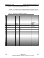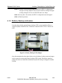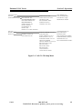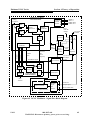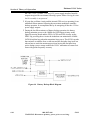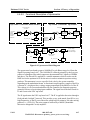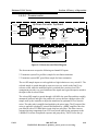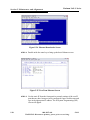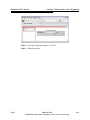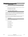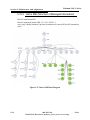
1
TECHNICAL MANUAL 888-2857-001 Platinum VAX-C Compact Class Transmitter Platinum VAX-C Compact Class Transmitter Technical Manual Harris Broadcast This document covers the following modulations: ATSC/MH DVB-T/H DVBT-2 ISDB-T/H CTTB CMMB DAB DMB T.M. No. 888-2857-001 © Copyright Harris Broadcast 2012, 2013 All rights reserved 07May2013 Rev: B ii 888-2857-001 WARNING: Disconnect primary power prior to servicing. 5/9/13 Technical Assistance Technical and troubleshooting assistance for Harris transmission products is available from Harris field service (factory location: Quincy, Illinois, USA) during normal business hours (8:00 AM - 5:00 PM Central Time). Telephone +1-217-222-8200 to contact the field service department; FAX +1-217-221-7086; or E-mail questions to [email protected]. Emergency service is available 24 hours a day, seven days a week, by telephone only. Online assistance, including technical manuals, white papers, software downloads, and service bulletins, is available at http://support.broadcast.harris.com/eservice_enu. Address written correspondence to Field Service Department, Harris Broadcast, P.O. Box 4290, Quincy, Illinois 62305-4290, USA. For other global service contact information, please visit: http://www.broadcast.harris.com/contact. NOTE: For all service and parts correspondence, you will need to provide the sales order number, as well as the serial number for the transmitter or part in question. For future reference, record those numbers here: ___________________/____________________ Please provide these numbers for any written request, or have these numbers ready in the event you choose to call regarding any service, or parts requests. For warranty claims it will be required. For out of warranty products, this will help us to best identify what specific hardware was shipped. Replaceable Parts Service Replacement parts are available from Harris service parts department from 7:00 AM to 11:00 PM Central Time, seven days a week. Telephone +1-217-222-8200 or email [email protected] to contact the Service Parts Department. Emergency replacement parts are available by telephone only, 24 hours a day, seven days a week by calling +1-217-222-8200. Unpacking Carefully unpack the equipment and perform a visual inspection to determine if any apparent damage was incurred during shipment. Retain the shipping materials until it has been verified that all equipment has been received undamaged. Locate and retain all packing check lists. Use the packing check list to help locate and identify any components or assemblies which are removed for shipping and must be reinstalled. Also remove any shipping supports, straps, and packing materials prior to initial turn on. Returns And Exchanges No equipment can be returned unless written approval and a Return Authorization is received from Harris Broadcast. Special shipping instructions and coding will be provided to assure proper handling. Complete details regarding circumstances and reasons for return are to be included in the request for return. Custom equipment or special order equipment is not returnable. In those instances where return or exchange of equipment is at the request of the customer, or convenience of the customer, a restocking fee will be charged. All returns will be sent freight prepaid and properly insured by the customer. When communicating with Harris Broadcast, specify the Harris order number or invoice number. 5/9/13 888-2857-001 WARNING: Disconnect primary power prior to servicing. iii Service Centres Europe Harris Broadcast Eskdale Road, Winnersh, Wokingham, Berkshire, U.K. RG41 5TS Telephone: +44 (0) 118 964 8100. FAX: +44 (0) 118 964 8054 e-mail: [email protected] Asia Leitch Asia Limited & Harris Communications Limited Rm 1015-18, 10/F, Tower 1, Grand Century Place, 193 Prince Edward Road West, Kowloon, Hong Kong Telephone: +852-2174 2504 FAX: +852-2776 0227 email: [email protected] Americas / Factory Harris Broadcast P.O. Box 4290, Quincy, Illinois 62305-4290, USA. Telephone: +1 217 222 8200 (24/7/365 emergency support) FAX: +1 217 221 7086 e-mail: [email protected] (tech assistance) [email protected] (parts only) For other global service contact information, please visit: http:// www.broadcast.harris.com/contact. At Harris Broadcast, we endeavor to offer the finest equipment manuals available today in the broadcast industry. If you encounter errors, omissions, or other areas in which this manual might be improved, we strongly encourage your to send your comments to [email protected]. Our ability to continually improve our technical documentation depends on your inputs! iv 888-2857-001 WARNING: Disconnect primary power prior to servicing. 5/9/13 Manual Revision History Platinum VAX-C Compact Class Technical Manual REV. DATE ECN A OCT 2012 P53357 Initial release. B 07May2013 62739 Updates to Sections 1 2 5 5/9/13 Pages Affected / Description 888-2857-001 MRH-1 WARNING: Disconnect primary power prior to servicing. Guide to Using Parts List Information The Replaceable Parts List Index portrays a tree structure with the major items being left most in the index. The example below shows the Transmitter as the highest item in the tree structure. If you were to look at the bill of materials table for the Transmitter you would find the Control Cabinet, the PA Cabinet, and the Output Cabinet. In the Replaceable Parts List Index the Control Cabinet, PA Cabinet, and Output Cabinet show up one indentation level below the Transmitter and implies that they are used in the Transmitter. The Controller Board is indented one level below the Control Cabinet so it will show up in the bill of material for the Control Cabinet. The tree structure of this same index is shown to the right of the table and shows indentation level versus tree structure level. Example of Replaceable Parts List Index and equivalent tree structure: Replaceable Parts List Index Part Number Table 7-1. Transmitter Table 7-2. Control Cabinet Table 7-3. Controller Board Table 7-4. PA Cabinet Table 7-5. PA Amplifier Table 7-6. PA Amplifier Board Table 7-7. Output Cabinet Transmitter 994 9283 001 Page 994 9283 001 992 9244 002 992 8344 002 992 9400 002 994 7894 002 992 7904 002 992 9450 001 7-2 7-3 7-6 7-7 7-9 7-10 7-12 Control Cabinet 992 9244 002 PA Cabinet 992 9400 002 Controller Board 992 8344 002 PA Amplifier 992 7894 002 Output Cabinet 992 9450 001 PA Amplifier Board 992 7904 002 The part number of the item is shown to the right of the description as is the page in the manual where the bill for that part number starts. Inside the actual tables, four main headings are used: • • • • • Table #-#. ITEM NAME - PART NUMBER - this line gives the information that corresponds to the Replaceable Parts List Index entry; P/N column gives the ten digit part number (usually in ascending order); DESCRIPTION column gives a 25 character or less description of the part number; REF. SYMBOLS/EXPLANATIONS column 1) gives the reference designators for the item (i.e., C001, R102, etc.) that corresponds to the number found in the schematics (C001 in a bill of material is equivalent to C1 on the schematic) or 2) gives added information or further explanation (i.e., “Used for 208V operation only,” or “Used for HT 10LS only,” etc.). NOTE: Inside the individual tables some standard conventions are used: • • • A # symbol in front of a component such as #C001 under the REF. SYMBOLS/EXPLANATIONS column means that this item is used on or with C001 and is not the actual part number for C001. In the ten digit part numbers, if the last three numbers are 000, the item is a part that has been purchased and has not manufactured or modified. If the last three numbers are other than 000, the item is either manufactured or is purchased from a vendor and modified for use in the product. The first three digits of the ten digit part number tell which family the part number belongs to - for example, all electrolytic (can) capacitors will be in the same family (524 xxxx 000). If an electrolytic (can) capacitor is found to have a 9xx xxxx xxx part number (a number outside of the normal family of numbers), it has probably been modified in some manner at the factory and will therefore show up farther down into the individual parts list (because each table is normally sorted in ascending order). Most made or modified assemblies will have 9xx xxxx xxx numbers associated with them. The term “SEE HIGHER LEVEL BILL” in the description column implies that the reference designated part number will show up in a bill that is higher in the tree structure. This is often the case for components that may be frequency determinant or voltage determinant and are called out in a higher level bill structure that is more customer dependent than the bill at a lower level. vi 888-2857-001 WARNING: Disconnect primary power prior to servicing. 5/9/13 5/9/13 888-2857-001 WARNING: Disconnect primary power prior to servicing. vii Item ______________________________ Quantity Part Number ________________________________ ______________________________ Ref Des e.g. C21, R100, etc. Item Used On Assembly if Known e.g. C21 used on 992-8025-001 & Schematic 839-8038-991 Comments Guide for Ordering Parts: Please provide as much information as possible to facilitate part substitution as required. Equipment name, part number and serial number is found on a metal ID plate on the rear of the unit. Describe the unit using the parts list if possible. Include schematic information, schematic number, or number of next higher assembly. The next higher assembly usually has a part number that begins with a 9xx-xxxx-xxx. Shipping Method : ________________________ Preferred FAX: Telephone: ______________________________ ________________________________ ________________________________ ________________________________ Address: ________________________________ Description of Part Part’s Name, Description, and Specification from Parts List Equipment Serial Number:___________________ Equipment Part Number:____________________ Frequency & Channel: ______________________ Payment Method : ________________________ Preferred FAX: Telephone: ______________________________ ________________________________ ________________________________ ________________________________ Address: ________________________________ Shipping Information Phone: 217-222-8200 FAX: 217-221-7096 Ship To (If different from billing information): PARTS ORDER FORM Billing Information Customer Name: ________________________ Harris Broadcast PO Box 4290 3200 Wismann Lane 62305 viii 888-2857-001 WARNING: Disconnect primary power prior to servicing. 5/9/13 ! WARNING: THE CURRENTS AND VOLTAGES IN THIS EQUIPMENT ARE DANGEROUS. PERSONNEL MUST AT ALL TIMES OBSERVE SAFETY WARNINGS, INSTRUCTIONS AND REGULATIONS. This manual is intended as a general guide for trained and qualified personnel who are aware of the dangers inherent in handling potentially hazardous electrical/electronic circuits. It is not intended to contain a complete statement of all safety precautions which should be observed by personnel in using this or other electronic equipment. The installation, operation, maintenance and service of this equipment involves risks both to personnel and equipment, and must be performed only by qualified personnel exercising due care. Harris Broadcast shall not be responsible for injury or damage resulting from improper procedures or from the use of improperly trained or inexperienced personnel performing such tasks. During installation and operation of this equipment, local building codes and fire protection standards must be observed. The following National Fire Protection Association (NFPA) standards are recommended as reference: - Automatic Fire Detectors, No. 72E - Installation, Maintenance, and Use of Portable Fire Extinguishers, No. 10 - Halogenated Fire Extinguishing Agent Systems, No. 12A ! WARNING: ALWAYS DISCONNECT POWER BEFORE OPENING COVERS, DOORS, ENCLOSURES, GATES, PANELS OR SHIELDS. ALWAYS USE GROUNDING STICKS AND SHORT OUT HIGH VOLTAGE POINTS BEFORE SERVICING. NEVER MAKE INTERNAL ADJUSTMENTS, PERFORM MAINTENANCE OR SERVICE WHEN ALONE OR WHEN FATIGUED. Do not remove, short-circuit or tamper with interlock switches on access covers, doors, enclosures, gates, panels or shields. Keep away from live circuits, know your equipment and don’t take chances. ! WARNING: IN CASE OF EMERGENCY ENSURE THAT POWER HAS BEEN DISCONNECTED. IF OIL FILLED OR ELECTROLYTIC CAPACITORS ARE UTILIZED IN YOUR EQUIPMENT, AND IF A LEAK OR BULGE IS APPARENT ON THE CAPACITOR CASE WHEN THE UNIT IS OPENED FOR SERVICE OR MAINTENANCE, ALLOW THE UNIT TO COOL DOWN BEFORE ATTEMPTING TO REMOVE THE DEFECTIVE CAPACITOR. DO NOT ATTEMPT TO SERVICE A DEFECTIVE CAPACITOR WHILE IT IS HOT DUE TO THE POSSIBILITY OF A CASE RUPTURE AND SUBSEQUENT INJURY. ! WARNING: THERE IS DANGER OF EXPLOSION AND CHEMICAL EXPOSURE IF THE BATTERY IS NOT HANDLED, REMOVED, AND INSTALLED PROPERLY. ! WARNING: BATTERIES MUST NOT BE DISPOSED OF WITH DOMESTIC WASTE! SEND USED BATTERIES BACK TO THE MANUFACTURER OR SUPPLIER. 5/9/13 888-2857-001 WARNING: Disconnect primary power prior to servicing. ix x 888-2857-001 WARNING: Disconnect primary power prior to servicing. 5/9/13 FIRST-AID Personnel engaged in the installation, operation, maintenance or servicing of this equipment are urged to become familiar with first-aid theory and practices. The following information is not intended to be complete first-aid procedures, it is a brief and is only to be used as a reference. It is the duty of all personnel using the equipment to be prepared to give adequate Emergency First Aid and there by prevent avoidable loss of life. Treatment of Electrical Burns 1. Extensive burned and broken skin a. Cover area with clean sheet or cloth. (Cleanest available cloth article.) b. Do not break blisters, remove tissue, remove adhered particles of clothing, or apply any salve or ointment. c. Treat victim for shock as required. d. Arrange transportation to a hospital as quickly as possible. e. If arms or legs are affected keep them elevated. NOTE: If medical help will not be available within an hour and the victim is conscious and not vomiting, give him a weak solution of salt and soda: 1 level teaspoonful of salt and 1/2 level teaspoonful of baking soda to each quart of water (neither hot or cold). Allow victim to sip slowly about 4 ounces (a half of glass) over a period of 15 minutes. Discontinue fluid if vomiting occurs. (Do not give alcohol.) 2. Less severe burns - (1st & 2nd degree) a. Apply cool (not ice cold) compresses using the cleanest available cloth article. b. Do not break blisters, remove tissue, remove adhered particles of clothing, or apply salve or ointment. c. Apply clean dry dressing if necessary. d. Treat victim for shock as required. e. Arrange transportation to a hospital as quickly as possible. f. If arms or legs are affected keep them elevated. REFERENCE: ILLINOIS HEART ASSOCIATION AMERICAN RED CROSS STANDARD FIRST AID AND PERSONAL SAFETY MANUAL (SECOND EDITION) 5/9/13 888-2857-001 WARNING: Disconnect primary power prior to servicing. xi Glossary of Terms Analog Input Board (AIB): An optional circuit card for the modulator section of the low power unit (LPU). It provides the necessary interface to allow the modulator to accept analog video and audio inputs according to the PAL, NTSC, or SECAM standards. ASI (Asynchronous Serial Interface): A streaming format used to carry the MPEG transport stream from the network origination point to the transmitter for modulation onto the RF carrier(s). ATSC (Advanced Television Subcommittee): A digital television standard featuring a single, vestigial-sideband carrier and an 8VSB modulation constellation. The transport stream format may be either SMPTE310 or ASI: The data rate before forward error correction is 19.392658 Mbit/s. The transmitted data rate with error correction is 32.28 Mbit/s. Back Porch: The portion of the analog video horizontal line waveform following the sync pulse but before the start of active video. Band III: The VHF radio frequency band from 174 MHz to 230 MHz. In this manual, taken to mean the broadcast band from 168 MHz to 242 MHz covered by the VAX transmitter. BPF (Band pass filter): A high power filter centered about the desired channel bandwidth and located at the transmitter output port to eliminate out-of-band intermodulation products arising from the power amplification process. Also commonly referred to as the mask filter or critical mask filer. CAN (Controller Area Network): A serial communications standard designed to allow microcontrollers and devices to communicate with each other. xii 888-2857-001 WARNING: Disconnect primary power prior to servicing. 5/9/13 COFDM (Coded Orthogonal Frequency Division Multiplex): A transmission technique in which the information content of a complete ensemble (multiplex) is divided and modulated onto a multitude of closely neighboring RF carriers within a channel bandwidth (frequency block). The division of the information payload among a large number of RF carriers ensures that each individual RF carrier has a very low data rate (symbol rate). The long symbol period of the individual RF carriers allows the receiver to wait until all delayed signal reflections have arrived and been added to the direct signal (...during a guard interval to be discarded). This permits recovery a stable signal in difficult reception conditions, especially during mobile reception. CRC (Cyclic Redundancy Checksum): A procedure for error detection in digital signals. Before distribution to the transmitter, a CRC is computed for the transport stream signal. This CRC is sent in the transport stream. Upon reception at the transmitter site, another CRC is computed from the received transport stream and compared to the transmitted value. If the CRCs are identical, no error has occurred during the distribution to the transmitter site. DAB Mode (Digital Audio Broadcast): A digital radio/multimedia standard for transmitting multiple programs within a 1.5 MHz RF frequency block. The original DAB standard has been extended by two different enhancements to the encoding layer: DAB-Plus and DMB. All three standards use the original DAB modulation format in the transmitter (changes are upstream in the encoder). Four different DAB modes exist. All VAX transmitters use DAB mode I. DAC (Digital Analog Converter): A circuit that converts digital values inside the processing stages of the LPU modulator into analog RF waveforms for amplification and transmission by the transmitter. dBm (Decibels over 1 milliwatt): A logarithmic signal power measurement scale referenced to 1 mW. 0 dBm is equivalent to 1 mW. 10dBm = 10mW, 20dBm = 100mW, 30dBm = 1000mW. DMB (Digital Multimedia Broadcasting): A modification of the basic DAB system according to ETSI standard (TS 102 427 and TS 102 428) using MPEG-4 (H.264) and BSAC/HE-AAC V2 compression to 5/9/13 888-2857-001 WARNING: Disconnect primary power prior to servicing. xiii permit sending of multimedia information (radio, TV, and data casting) to mobile devices such as mobile phones. Originally developed in South Korea. DUC (Digital Upconverter): A circuit in the LPU modulator section that converts the digital modulated baseband signal to the 140 MHz digital intermediate frequency. Dynamic Delay: A processing function provided in the exciter to compensate for different delays of the program data stream in the data distribution network between the network origination point and various transmitter sites. A time-stamp contained in the transport stream serves as a reference. The present time is delivered by a GPS receiver at the transmitter (1pps signal, rising slope). Comparing these two sources, the dynamic delay function is able to synchronize the program input to all transmitters over a one-second correction range. Ensemble: The complete information payload being received and processed by the transmitter, typically when transmitting according to the DAB standard. In general, the ensemble includes audio programs, data services, and possibly video content. ETI (Ensemble Transport Interface): The transport stream format for DAB/DMB broadcasting (2.048 Mbit/s, G.703) used to send program material from the ensemble provider to all DAB transmitters in a network. The ETI format has two varieties: ETI-NA and ETI-NI. ETI(NA) (Network Adapted Layer): A protocol is suited for transmitting the ETI signal via telecom networks. It has a frame structure that complies with G.704 specifications and contains error protection information (Reed Solomon Code). The bit clock frequency is 2.048 MBit/s. ETI(NI) (Network Independent Layer): A protocol is suited for transmission with connections that have a low error rate and a constant signal delay. It does not contain any error protection information. The bit clock frequency is 2.048 MBit/s. ETI Input Board (EIB): xiv 888-2857-001 WARNING: Disconnect primary power prior to servicing. 5/9/13 An optional circuit card for the modulator section of the low power unit (LPU). It provides the necessary interface to allow the modulator to accept ETI transport streams according to the DAB digital transmission standard. Ethernet: The physical interface by which the VAX transmitter may be connected to a LAN and/or the Internet to provide web-based supervision. It generally employs an RJ45 connector. EVM (Error Vector Magnitude): A measure used to quantify the performance of the quality the digital being transmitted. A signal sent by an ideal transmitter would have all constellation points precisely at the ideal locations. However, various imperfections in the signal path cause the actual constellation points to deviate from the ideal locations by finite error vectors. Generally associated with the ATSC modulation standard. Analogous to the modulation error ration (MER) used for the DVB, DAB and other modulation standards. FPGA (Field Programmable Gate Array): An integrated circuit designed to be configured by the customer or designer after manufacturing. FPGAs perform many of the intensive digital processing steps used to synthesize the transmitted RF signal in the LPU modulator section. GPS (Global Positioning System): A satellite-based navigation system commonly used for determining position and navigating. In a single frequency network context, it delivers an extremely precise time reference (UTC... universal time, coordinated) used to synchronize all transmitters. Guard Interval: A time interval at the start of each transmitted symbol in a digital COFDM system. Distortions to the received signal due to time-delayed reflections or interfering transmitters falling in this interval are ignored by the receiver. GUI (Graphical User Interface): A type of user interface that allows users to interact with electronic devices via images rather than text commands. In this application, the user interface provided by the TCU touch screen in dual drive systems or the web-based remote interface served over the Ethernet interface. 5/9/13 888-2857-001 WARNING: Disconnect primary power prior to servicing. xv Hierarchical modes: A transmission technique whereby the transmitted data payload is divided into a lower data rate high priority (HP) stream and a higher data rate low priority (LP) stream. Those receivers with difficult reception conditions decode only the more robust HP data stream, while receivers with good reception conditions receive both data streams. Hot-pluggable: Term to denote that the device in question can be removed while transmitter is operating without suffering damage or causing damage to other devices. HTML (Hypertext Markup Language): The predominant markup language for web pages. HTML is the basic building block of web pages. IP Address (Internet Protocol Address): A numerical label assigned to each device (e.g., computer, printer) participating in a computer network that uses the Internet Protocol (IP) for communication. An IP address serves two principal functions: host or network interface identification and location addressing. LCD (Liquid Crystal Display): A thin, flat electronic visual display that uses the light modulating properties of liquid crystals to display text and images. In the VAX transmitter, the blue display screen on the front panel of the low power unit(s). LPF (Low Pass Filter): A high power filter located at the transmitter output port used to attenuate out-ofband emissions at the signal harmonic frequencies arising from the high power amplification process. May also be referred to as a harmonic filter. LPU (Low Power Unit): May also be referred to as the exciter. The LPU contains both an upper, modulator section and a lower, amplifier section. MER (Modulation Error Ratio): A measure used to quantify the performance of the quality the digital being transmitted. A signal sent by an ideal transmitter would have all constellation points xvi 888-2857-001 WARNING: Disconnect primary power prior to servicing. 5/9/13 precisely at the ideal locations. However various imperfections in the signal path cause the actual constellation points to deviate from the ideal locations by finite error vectors. The modulation error ratio quantifies the ratio of the desired signal to the undesired error vectors. MER is typically associated with COFDM modulation formats such as DVB or DAB. MCM (Master Control Module): A circuit card in the transmitter control unit (TCU) in dual drive systems. The MCM card provides most of the core control functions, whereas the TCU card controls the user remote & GUI interface. PA (Power amplifier): An electronic circuit that accepts a low level RF signal and outputs an amplified replica. PAB (Power amplifier block): A high power amplifier stage. May refer to the LPU power block (PAB zero in lower-half amplifier section of LPU chassis) or one or more external high power amplification stages (PAB 1…4). PCB (Printed Circuit Board): A circuit board in the transmitter. PCM (Processor Control Module): A circuit card in the transmitter control unit (TCU) in dual drive systems. The MCM card provides most of the core control functions, whereas the TCU card controls the user remote & GUI interface. PFRU (Precise Frequency Reference Unit): A circuit sub-assembly inside the LPU modulator section responsible for supplying the various high-stability oscillator signals required to synthesize the transmitted RF waveform. PRBS (Pseudo-random binary sequence): An endless series of random numbers typically used for transmitter test purposes, often when a valid transport stream does not exist. 5/9/13 888-2857-001 WARNING: Disconnect primary power prior to servicing. xvii PS (Power supply): A device that supplies DC electrical energy to one or more electric loads, typically via the rectification of an AC mains electrical input. RF (Radio frequency): An electrical oscillation at the frequency of radio waves in the range of 3 kHz to 300 GHz. In this application, typically a signal in the 168 MHz to 242 MHz frequency range of the VAX transmitter. RS-485: A TIA/EIA standard for serial multipoint communications lines. The signal communication protocol used for serial communications between various subassemblies in the transmitter system. Also known as EIA-485 or TIA-485. RTAC (Real Time Adaptive Correction): A signal processing technique applied in the modulator signal generation stage which seeks to correct deficiencies in the high power amplification and filtering stages by means of complementary pre-distortion. RU: An abbreviation for rack unit.One rack unit equals 1.75" (44.45mm). The rack unit is used to describe the height of components that will be placed in racks. SFN (Single Frequency Network): A transmission network in which all transmitters are synchronized in frequency and phase (symbol). This transmission technique guarantees high frequency economy, as a single frequency can be used in a large geographic area. SMA (SMA connector): A coaxial connector for RF cables featuring a 0.250 x 36 thread and a .312 inch (7.925mm) hex nut in the male connector. SMPTE (SMPTE 310 transport stream): A transport stream format sometimes employed with the ATSC digital television standard. xviii 888-2857-001 WARNING: Disconnect primary power prior to servicing. 5/9/13 Static Delay: A delay function provided by the exciter over a manually settable range of 0 to 1000 ms to compensate for differences in signal processing delays or local propagation conditions for individual transmitters in a single frequency network. Sync (Sync pulse): The horizontal synchronization pulse in the video waveform which, when transmitted, creates the highest level of peak envelope power in the transmitter. TII (Transmitter Identification Information): A data field transmitted during the null in the DAB RF frame containing transmitter identification information for use by the receiver. Each transmitter in a single frequency network has its own unique TII identifier. Time stamps: Data fields in the transmission protocol (e.g. in the ETI signal) containing timing information for the purposes of signal monitoring and synchronization. TS (Transport Stream): A standard format for transmission and storage of audio, video, and data for broadcast systems such as DVB and ATSC. The transport stream specifies a container format encapsulating packetized elementary streams, with error correction and stream synchronization features for maintaining transmission integrity when the signal is degraded. Depending on the digital transmission standard, the transport stream may be in the SMPTE310, ASI, or ETI format. TPO (Transmitter Power Output): The desired transmitter forward output power level. UDC (Up-Down Converter): A circuit in the LPU modulator section that converts an 140 MHz intermediate frequency signal to the final desired VHF RF channel frequency (upconversion) or vice versa (downconversion) UPS (Uninterruptable Power Supply): 5/9/13 888-2857-001 WARNING: Disconnect primary power prior to servicing. xix A battery-based system designed to provide power during an AC mains failure event. VGA (Video Graphics Array): A video display standard used by the personal computer industry based on a 640 x 480 pixel resolution. The standard used by the TCU touchscreen in dual drive systems. VHF (Very High Frequency): The radio frequency range of 30 MHz to 300 MHz. In this application, the 168 MHz to 242 MHz frequency band covered by the VAX transmitter. WEB: A device or interface that uses HTML formatted documents transmitted according to the IP protocol, typically over LAN/WAN/Internet servers, but also locally via 1:1 communications. References Please also consult the following references for additional information on DAB technical requirements: xx • TR 101 496: "Digital Audio Broadcasting (DAB); Guidelines and rules for implementation and operation" • ETS 300 401: ”Radio broadcast systems; Digital Audio Broadcasting (DAB) to mobile, portable, portable and fixed receivers” • ETS 300 799: "Digital Audio Broadcasting (DAB); Distribution Interfaces; Ensemble Transport Interface (ETI)" • ITU-T Recommendation G.703: “General Aspects of Digital Transmission Equipment; Terminal Equipment. Physical/electrical Characteristics of Hierarchical Digital Interfaces, Geneva, 1994” • ITU: “Radio Regulations, Appendix 8, Geneva, 1994” 888-2857-001 WARNING: Disconnect primary power prior to servicing. 5/9/13 Table of Contents User Remote Connector . . . . . . . . . . . . . . . . . . .2-11 Transmitter Interface Connector. . . . . . . . . . . . .2-13 TS (Transport Stream) Connections . . . . . . . . . .2-14 External Interlock . . . . . . . . . . . . . . . . . . . . . . . . .2-14 Cooling System. . . . . . . . . . . . . . . . . . . . . . . . . . .2-14 RF Connections. . . . . . . . . . . . . . . . . . . . . . . . . . .2-16 RF Output . . . . . . . . . . . . . . . . . . . . . . . . . . . . . .2-16 RF Sample Connections and Level . . . . . . . . . .2-16 Transmitter Power Up . . . . . . . . . . . . . . . . . . . . . .2-18 Battery Backup Activation . . . . . . . . . . . . . . . . . .2-19 Glossary of Terms . . . . . . . . . . . . . . . . . . . . . . . . 1-xii References . . . . . . . . . . . . . . . . . . . . . . . . . . . . . . 1-xx Section 1 Introduction Purpose of Manual . . . . . . . . . . . . . . . . . . . . . . . . 1-1 VAX-C Features / Benefits . . . . . . . . . . . . . . . . . . 1-2 General Description. . . . . . . . . . . . . . . . . . . . . . . . 1-3 Transmitter Models . . . . . . . . . . . . . . . . . . . . . . . . 1-5 VAX Transmitter System . . . . . . . . . . . . . . . . . . . 1-7 Transmitter RF Power Control . . . . . . . . . . . . . . 1-7 Software . . . . . . . . . . . . . . . . . . . . . . . . . . . . . . . 1-7 Remote Control. . . . . . . . . . . . . . . . . . . . . . . . . . 1-7 Operating Voltages . . . . . . . . . . . . . . . . . . . . . . . . 1-8 Block Diagram . . . . . . . . . . . . . . . . . . . . . . . . . . . 1-9 Transmitter Accessories . . . . . . . . . . . . . . . . . . . 1-10 Rack Integration . . . . . . . . . . . . . . . . . . . . . . . . 1-10 Directional Coupler or Wattmeter . . . . . . . . . . 1-10 VAX-C Exciter/Controller. . . . . . . . . . . . . . . . . . 1-11 Inputs and Outputs . . . . . . . . . . . . . . . . . . . . . . 1-11 VAX-C Specifications . . . . . . . . . . . . . . . . . . . . . 1-13 General Specifications . . . . . . . . . . . . . . . . . . . 1-13 COFDM Specifications . . . . . . . . . . . . . . . . . . 1-15 ATSC Specifications. . . . . . . . . . . . . . . . . . . . . 1-16 DAB/DMB Specifications . . . . . . . . . . . . . . . . 1-17 Section 3 Operation Transmitter Control. . . . . . . . . . . . . . . . . . . . . . . . .3-1 Transmitter Control Panel . . . . . . . . . . . . . . . . . .3-2 LCD Menus . . . . . . . . . . . . . . . . . . . . . . . . . . . . .3-3 Front Panel LEDs . . . . . . . . . . . . . . . . . . . . . . . . .3-6 Xmtr Home Screen . . . . . . . . . . . . . . . . . . . . . . . . .3-8 Output Screen . . . . . . . . . . . . . . . . . . . . . . . . . . .3-10 Amplifier Screen . . . . . . . . . . . . . . . . . . . . . . . .3-11 Configuration Screens . . . . . . . . . . . . . . . . . . . .3-12 System Calibration Screens. . . . . . . . . . . . . . . .3-14 Exciter Home Screen . . . . . . . . . . . . . . . . . . . . . .3-17 Fault Log screens . . . . . . . . . . . . . . . . . . . . . . . .3-20 SETUP SCREENS, All Modulation Systems. . . .3-21 ISP (In-System Programming) Screen . . . . . . . .3-22 Save Settings Soft Key . . . . . . . . . . . . . . . . . . . . . . 3-23 Section 2 Installation / Initial Turn-On RTAC Setup Screens 1 & 2 . . . . . . . . . . . . . . . .3-24 Storing an RTAC Correction Set . . . . . . . . . . . . . . . 3-26 Operate RTAC from a Stored Filter Set. . . . . . . . . . 3-26 DUC/RTAC Setup Screen 3 & 4 . . . . . . . . . . . .3-27 Introduction . . . . . . . . . . . . . . . . . . . . . . . . . . . . . . 2-1 Unpacking . . . . . . . . . . . . . . . . . . . . . . . . . . . . . . . 2-1 Returns and Exchanges . . . . . . . . . . . . . . . . . . . . . 2-1 Documentation . . . . . . . . . . . . . . . . . . . . . . . . . . . 2-2 Technical Manual and Drawings . . . . . . . . . . . . 2-2 Installation. . . . . . . . . . . . . . . . . . . . . . . . . . . . . . . 2-3 Transmitter Placement and Operating Environment2-3 Rack Mounting Components . . . . . . . . . . . . . . . 2-4 Transmitter AC and Ground Connections. . . . . . . 2-5 Surge Suppression Devices. . . . . . . . . . . . . . . . . 2-5 Voltage Regulation . . . . . . . . . . . . . . . . . . . . . . . 2-5 Safety Ground. . . . . . . . . . . . . . . . . . . . . . . . . . . 2-5 Cabinet Ground Strap . . . . . . . . . . . . . . . . . . . . . 2-7 Connecting AC Power . . . . . . . . . . . . . . . . . . . . 2-7 Signal and Sample Connections . . . . . . . . . . . . . . 2-9 Rear Panel Connections . . . . . . . . . . . . . . . . . . . 2-9 Nonlinear Correction Range Setup . . . . . . . . . . . . . 3-28 Max Crest Factor Setup . . . . . . . . . . . . . . . . . . . . . . 3-29 RTAC Profiles sub window . . . . . . . . . . . . . . . . . . . 3-30 Transmitter I/O Screen . . . . . . . . . . . . . . . . . . . .3-31 PFRU Setup . . . . . . . . . . . . . . . . . . . . . . . . . . . .3-33 Remote Communications Screens . . . . . . . . . . .3-35 User Settings Screen. . . . . . . . . . . . . . . . . . . . . .3-37 System Settings Screens. . . . . . . . . . . . . . . . . . .3-39 Setup Screens - ATSC Modulation . . . . . . . . . . .3-41 Setup Screens - CTTB/CMMB Modulation . . . .3-44 SETUP - ISDB-T MODULATION . . . . . . . . . . .3-49 Setup Screens - DVB-T Modulation . . . . . . . . . .3-53 Setup Screens - DVB-T2 Modulation . . . . . . . . .3-63 Setup Screens - DAB Modulation. . . . . . . . . . . . .3-76 Status Screens, All Modulation Systems . . . . . . .3-81 Signal Processor Status Screens . . . . . . . . . . . . .3-82 1 Table of Contents PS Module Removal/Replacement . . . . . . . . . . . . 5-8 Power Calibrations . . . . . . . . . . . . . . . . . . . . . . . 5-10 System Factory Fwd/Rfld Calibration . . . . . . . 5-12 DUC/RTAC or UDC Output Status Screen. . . . 3-84 Transmitter I/O Status screen . . . . . . . . . . . . . . 3-85 PFRU Status Screens. . . . . . . . . . . . . . . . . . . . . 3-87 Battery Backup Status Screen . . . . . . . . . . . . . . 3-90 Revisions Status Screens (1 & 2) . . . . . . . . . . . 3-91 Status Screens - ATSC Modulation . . . . . . . . . . 3-92 Status Screens - CTTB/CMMB Modulation . . . 3-97 Status Screens - ISDB-T Modulation . . . . . . . . 3-102 Status Screens - DVB-T Modulation . . . . . . . . 3-106 Status Screens - DVB-T2 Modulation . . . . . . . . 3-109 Status Screens - DAB Modulator. . . . . . . . . . . . 3-111 Calibration Errors . . . . . . . . . . . . . . . . . . . . . . . . . . 5-14 Field Fwd/Rfld Calibration . . . . . . . . . . . . . . . . 5-14 Calibration Errors . . . . . . . . . . . . . . . . . . . . . . . . . 5-16 Pre-correction for Digital TV & DAB. . . . . . . . . 5-17 Precorrection Setup Procedure . . . . . . . . . . . . . 5-17 Troubleshooting Precorrection . . . . . . . . . . . . . . . . 5-18 Storing Precorrection . . . . . . . . . . . . . . . . . . . . Changing Frequency . . . . . . . . . . . . . . . . . . . . . . Fan Replacement . . . . . . . . . . . . . . . . . . . . . . . . Air Filter Replacement . . . . . . . . . . . . . . . . . . . . Cleaning. . . . . . . . . . . . . . . . . . . . . . . . . . . . . . . . Changing Date and Time Battery . . . . . . . . . . . . Setting VAX-C Date and Time . . . . . . . . . . . . . Battery Backup (UPS) Option . . . . . . . . . . . . . Changing Feature Key. . . . . . . . . . . . . . . . . . . . . Connecting To The VAX-C . . . . . . . . . . . . . . . . . VAX-C Front and Rear RJ45 Connectors . . . . Log- In Authorization Levels & Passwords . . . Changing Passwords . . . . . . . . . . . . . . . . . . . . . Connection Via Front Ethernet Connector . . . . Section 4 Theory of Operation Introduction . . . . . . . . . . . . . . . . . . . . . . . . . . . . . . 4-1 Active Logic Symbols . . . . . . . . . . . . . . . . . . . . . . 4-1 Block Diagram. . . . . . . . . . . . . . . . . . . . . . . . . . . . 4-2 Modulator Overview . . . . . . . . . . . . . . . . . . . . . . . 4-4 Signal Processor Board Overview . . . . . . . . . . . 4-6 The Modulation Process . . . . . . . . . . . . . . . . . . . 4-7 RF Sample Processing. . . . . . . . . . . . . . . . . . . . . 4-7 Low Voltage Power Supply Board . . . . . . . . . . . 4-8 Battery Backup Option . . . . . . . . . . . . . . . . . . . . 4-9 ASI / SMPTE 310 Inputs / Output . . . . . . . . . . 4-11 PFRU (Precise Frequency Reference Unit) Board4-12 Assigning Computer IP Address in DHCP Client Mode5-35 Assigning Computer IP Address Without Rebooting5-35 Making the Connection to the VAX-C . . . . . . . . . . 5-36 Obtaining Rear Ethernet Connector Address . . . . . 5-36 PFRU Board 1st LO PLL for the DAC Clock Circuit4-12 PFRU Board Local Oscillator-2 Circuit, For UDC 4-14 PFRU Board Reference Oscillator Circuit . . . . . . . 4-15 PFRU Board GPS Circuit . . . . . . . . . . . . . . . . . . . . 4-16 Connecting Via VAX-C Rear Panel Ethernet Connector537 Connecting To VAX-C Via Existing Ethernet Network5-37 Direct Connection, Computer To VAX-C Rear Ethernet Connector. . . . . . . . . . . . . . . . . . . . . . . . . . . . . . . . . . . 5-38 Up/Downconverter Board . . . . . . . . . . . . . . . . . 4-16 Upconverter Major Specifications . . . . . . . . . . . . . 4-16 Functional Description of Upconverter . . . . . . . . . 4-17 Downconverter Major Specifications . . . . . . . . . . . 4-18 Downconverter . . . . . . . . . . . . . . . . . . . . . . . . . . . . 4-19 LO Distribution. . . . . . . . . . . . . . . . . . . . . . . . . . . . 4-20 Changing PC Operating Mode Static/DHCP . . 5-38 Verifying The Computer IP Address . . . . . . . . . . . 5-39 VAX-C Screen Captures . . . . . . . . . . . . . . . . . . . . . 5-40 Updating VAX-C Software . . . . . . . . . . . . . . . . . 5-41 Saving and Recalling Settings . . . . . . . . . . . . . 5-46 Web Browser Screen Captures . . . . . . . . . . . . . 5-47 Bootloader Recovery Procedure . . . . . . . . . . . . . 5-48 Connecting to the VAX via SNMP . . . . . . . . . . . 5-52 SNMP Configuration . . . . . . . . . . . . . . . . . . . . 5-52 Supported MIBs . . . . . . . . . . . . . . . . . . . . . . . . 5-53 Harris Base MIB Description . . . . . . . . . . . . . . 5-53 Shortcuts . . . . . . . . . . . . . . . . . . . . . . . . . . . . . . 5-53 Harris SMI (Structure of Managed Information)5-54 DAB Single Frequency Network (SFN) Setup . 5-56 Dynamic Delay . . . . . . . . . . . . . . . . . . . . . . . . . 5-56 Static Delay. . . . . . . . . . . . . . . . . . . . . . . . . . . . 5-56 VAX-C Transmitter PAs . . . . . . . . . . . . . . . . . . . 4-21 Fault Protection. . . . . . . . . . . . . . . . . . . . . . . . . . . . 4-21 RF Power Detection and Calibration . . . . . . . . . . . 4-21 +50 VDC Power Supply Interface . . . . . . . . . . . . . 4-22 Section 5 Maintenance and Alignments Technical Assistance . . . . . . . . . . . . . . . . . . . . . . . PA Module Removal and Replacement . . . . . . . . . PA Module Removal . . . . . . . . . . . . . . . . . . . . . . PA Module Installation . . . . . . . . . . . . . . . . . . . . 5-18 5-20 5-23 5-24 5-25 5-26 5-27 5-27 5-29 5-31 5-31 5-32 5-33 5-34 5-1 5-2 5-2 5-6 2 Table of Contents Offset Delay . . . . . . . . . . . . . . . . . . . . . . . . . . . DAB EDI/IP Input Option. . . . . . . . . . . . . . . . . . Overview . . . . . . . . . . . . . . . . . . . . . . . . . . . . . Installation and Setup . . . . . . . . . . . . . . . . . . . . Inputs/Outputs . . . . . . . . . . . . . . . . . . . . . . . . . Operation . . . . . . . . . . . . . . . . . . . . . . . . . . . . . M2X, LPU or VAX Interface . . . . . . . . . . . . . . GUI Screens . . . . . . . . . . . . . . . . . . . . . . . . . . . References . . . . . . . . . . . . . . . . . . . . . . . . . . . . EDI Software Update . . . . . . . . . . . . . . . . . . . . Typical Test Equipment. . . . . . . . . . . . . . . . . . . . 5-57 5-58 5-58 5-58 5-59 5-59 5-59 5-60 5-60 5-60 5-62 Section 6 Diagnostics Introduction . . . . . . . . . . . . . . . . . . . . . . . . . . . . . . 6-1 Web Browser Fault Log . . . . . . . . . . . . . . . . . . . . 6-2 Fault Tables . . . . . . . . . . . . . . . . . . . . . . . . . . . . . . 6-4 PA Faults . . . . . . . . . . . . . . . . . . . . . . . . . . . . . 6-15 Section 7 Parts List Replaceable Parts List . . . . . . . . . . . . . . . . . . . . . . 7-1 3 Table of Contents 4 Platinum VAX-C Series Section 1 Introduction 1.1 1 Purpose of Manual This manual provides important information for the proper operation and maintenance of the VAX family of air cooled, solid state, VHF transmitters. Schematics and diagrams are provided in an accompanying drawing package. This manual is written for the skilled broadcast maintenance technician and assumes previous experience working with RF broadcast equipment. The various sections of this technical manual provide the following types of information: • Section 1: Introduction, identifies the versions of the product available and the possible options. • Section 2: Installation, details the procedures to receive, install, and commission the transmitter for use, including initial start-up procedure. • Section 3: Operation, describes operation of the equipment and is intended to be the primary section referenced by operating personnel. • Section 4: Theory of Operation, is included to help service personnel understand the inner workings of the transmitter. • Section 5: Maintenance, lists and explains alignments and adjustments that could be required to maintain the transmitter. • Section 6: Troubleshooting, included as a service aid to be used along with Sections 4 and 5 by qualified service personnel to identify and correct an equipment malfunction. • Section 7: Parts List, a comprehensive listing of the components that may be replaced in the field. NOTE: If a "customer-special" manual is included with a custom-built transmitter, the information in that manual supercedes that contained in this manual. 5/9/13 888-2857-001 WARNING: Disconnect primary power prior to servicing. 1-1 Section 1 Introduction 1.2 Platinum VAX-C Series VAX-C Features / Benefits The Harris VAX-C Compact Class transmitter offers the following useful features and benefits: • Easy migration between different modulation standards. Nearly all digital TV and DAB/DMB standards are available by software upgrade. NOTE: If different modulation standards are required, then a new feature key must be entered into the controller to activate additional modulation types and options. Contact Harris sales to obtain information and pricing for new feature keys. 1-2 • Rugged, reliable design and construction - Compact design utilizing only 2 RU (rack unit) space. • New 50-volt LDMOS device technology delivers a dramatic increase in power density. • PowerSmart technology, for best-in-class power efficiency and lowest operating costs • • Digital power levels 5 to 100 W COFDM, 5 to 150 W DAB, 5 to 180 W ATSC • • • • Fully Broadband PA Modules — VHF, bands III, 168 to 242 MHz All-digital linear and non-linear pre-correction utilizing Real-Time Adaptive Correction (RTAC™) Automatic restart after AC mains interruption - returns to previous operational mode Modular control system for straightforward monitoring and in-depth diagnostics Harris® web-enabled remote GUI interface 888-2857-001 WARNING: Disconnect primary power prior to servicing. 5/9/13 Platinum VAX-C Series 1.3 Section 1 Introduction General Description This section contains a general description of the Platinum VAX-C Series of television transmitters. Included in this section will be descriptions of the control system, amplifier, block diagrams of the various models and system specifications. The VAX-C series of solid state, air cooled, transmitters is designed to synthesize and amplify radio- frequency signals in the VHF broadcast bands III (168 to 242 MHz). VAX-C transmitters contain the following assemblies: control panel, exciter, controller and amplifier. The major components are shown in Figures 1-1, 1-2 & 1-3. Figure 1-1 VAX-C Transmitter - Front Panel Figure 1-2 VAX-C Transmitter - Top (cover removed) 5/9/13 888-2857-001 WARNING: Disconnect primary power prior to servicing. 1-3 Platinum VAX-C Series Section 1 Introduction Figure 1-3 VAX-C Rear Panel The Platinum VAX-C series of solid state, air-cooled transmitters is designed to synthesize and amplify radio frequency signals in the VHF TV and DAB/DMB broadcast band III 168-242 MHz. As of this printing, VAX transmitters support the following TV and radio formats: DAB = Digital Audio Broadcasting DABPlus = Digital Audio Broadcasting DMB = Digital Multimedia Broadcasting ATSC = American Television Standards Committee DTV ATSC A110 = Single frequency network standard for ATSC ATSC-M/H = Mobile TV standard for ATSC ISDB-T = South American and Japanese digital DTV DVB-T = Digital Video Broadcasting – Terrestrial DVB-T2 = Digital Video Broadcasting – Terrestrial DVB-H = Digital Video Broadcasting – Handheld CMMB = Chinese multimedia standard CTTB(DTMB) = Chinese multimedia standard 1-4 888-2857-001 WARNING: Disconnect primary power prior to servicing. 5/9/13 Section 1 Introduction Platinum VAX-C Series 1.4 Transmitter Models VAX-C transmitter model numbers are formed based on the following: ‘V’ stands for VHF Band, while ‘A’ means that air is used for cooling, ‘X’ indicates that the unit is a TV Transmitter, and ’C’ stands for compact class. The number following the VAX prefix stands for the transmitter power level. The suffix indicates the modulation type. The suffix ‘AT’ indicates ‘ATSC’. Other abbreviations include: MH for ATSC Mobile Handheld, DV for ‘DVB-T/H’, T2 for DVB-T2, IS for ’ISDB-T’, CT for CTTB, CM for ’CMMB’, DA for DAB, and DM for DMB digital modulations standards. The suffix set will be extended for additional modulation standards as required. For example: VAX-180AT-C = VHF, air cooled, TV transmitter, 180W, compact class, ATSC (digital) VAX-100DV-C = VHF, air cooled, TV transmitter, 100W, compact class, DVB-T (digital) The Platinum VAX-C Compact Class transmitters are available in four air cooled power levels. The models are listed below in Table 1-1. Table 1-1 Platinum VAX-C DAB Transmitter Models Tx Models Configuration Output Power (average) VAX-75DA-C 2RU 75 W VAX-150DA-C 2RU 150 W NOTES: All power levels given in average power at the transmitter output (prefilter). RU = rack unit. 1RU = 4.45 cm (1.75") 5/9/13 888-2857-001 WARNING: Disconnect primary power prior to servicing. 1-5 Platinum VAX-C Series Section 1 Introduction Table 1-2 Platinum VAX-C COFDM TV Transmitter Models Tx Models Configuration Output Power (average) VAX-50XX-C 2RU 50 W VAX-100XX-C 2RU 100 W NOTES: All power levels given in average power at the transmitter output (prefilter). RU = rack unit. 1RU = 4.45 cm (1.75") NOTE: In the table above the suffix XX is an indicator of modulation type. The following suffixes are used: DV=DVB-T/H, T2=DVB-T2, IS=ISDB-T, CT=CTTB, CM=CMMB. Table 1-3 Platinum VAX-C ATSC Transmitter Models Tx Models Configuration Output Power (average) VAX-90AT-C 2RU 90 W VAX-180AT-C 2RU 180 W NOTES: All power levels given in average power at the transmitter output (prefilter). RU = rack unit. 1RU = 4.45 cm (1.75") 1-6 888-2857-001 WARNING: Disconnect primary power prior to servicing. 5/9/13 Platinum VAX-C Series 1.5 Section 1 Introduction VAX Transmitter System VAX-C transmitters feature solid-state design and utilize a FET-based power amplifier (PA) module to amplify the RF signal. In addition to RF drive power from the exciter stage, the PA module utilizes 50V DC power, supplied by a switch mode power supply (PS) module. The PA module type varies with power level. The VAX-C features two cooling fans that can be changed by removing the front panel while the transmitter is on-air. Transmitters are typically supplied without a rack. Rack mounting is available as an option. The VAX-C system control is provided by the microprocessor daughter board which is mounted on the signal processing board, as shown in Figure 1-2 on page 1-3. SNMP communications and IP connectivity are standard offerings and available in all transmitter models. The VAX-C transmitter has an LCD display and control buttons on the front panel to allow the user to locally control the transmitter as shown in Figure 11 on page 1-3. LCD panel and push button control provides limited control of the transmitter system. The feature key and modulation settings can’t be changed using the LCD control panel push buttons. The web browser must be used to change these parameters. 1.5.1 Transmitter RF Power Control The PA module itself operates in open loop mode (no gain or level adjustment). The transmitter RF power control is done via automatic level control located in the VAX-C upconverter. 1.5.2 Software The transmitter is shipped from the factory with software preloaded and ready to run. If a software update is required, follow the instructions in the maintenance and alignment section. Software can be easily updated using the web browser and ISP (In System Programming). ISP is a Harris programming utility that is selectable as part of the web browser interface. See 3.4.1 for further details. 1.5.3 Remote Control The Platinum VAX-C transmitter has a wired parallel remote control with the standard connections for control, status and analog monitoring located on the customer I/O card in the rear panel. Detailed information on the remote control connections to the VAX-C and cabinet can be found in Section 2.7. 5/9/13 888-2857-001 WARNING: Disconnect primary power prior to servicing. 1-7 Section 1 Introduction Platinum VAX-C Series Platinum VAX-C transmitters include a Web enabled remote GUI interface that provides comprehensive remote control and monitoring of data points within the transmitter. It includes an SNMP (simple network management protocol) manager which allows integration with most control systems via the Internet or LAN. 1.6 Operating Voltages Single phase, 100 to 240 V AC, auto-ranging, +/-10%, 50/60 Hz, one IEC C15 inlet. ! CAUTION: CHECK THE AC POWER FEEDING THE VAX-C. IT MUST BE BETWEEN 100 VAC AND 240 VAC +/-10%. ANY VOLTAGE OUTSIDE THAT RANGE WILL CAUSE DAMAGE TO THE EQUIPMENT. THE VOLTAGE SHOULD BE MEASURED LINE TO LINE, OR WHEN A NEUTRAL IS USED, LINE TO NEUTRAL. ! CAUTION: IF VOLTAGE VARIATIONS IN EXCESS OF +/-10% ARE ANTICIPATED, THE TRANSMITTER POWER INPUT MUST BE EQUIPPED WITH AUTOMATIC VOLTAGE REGULATORS (OPTIONAL EQUIPMENT) CAPABLE OF CORRECTING THE MAINS VOLTAGE. 1-8 888-2857-001 WARNING: Disconnect primary power prior to servicing. 5/9/13 Section 1 Introduction Platinum VAX-C Series 1.7 Block Diagram Figure 1-4 on page 1-9 contains a system block diagram showing the basic RF signal flow and configuration for a Platinum VAX-C transmitter. PA Module Battery Backup Option Figure 1-4 VAX-C Simplified Block Diagram 5/9/13 888-2857-001 WARNING: Disconnect primary power prior to servicing. 1-9 Section 1 Introduction 1.8 Platinum VAX-C Series Transmitter Accessories The VAX-C chassis contains the basic VAX transmitter. Additional options are available and may be present in a VAX-C transmitter system. In as much as these accessories do not significantly change the functioning of the core transmitter itself, it is understood that this manual addresses customized transmitter configurations that may contain one or more of these options. In the case of a relatively high level of customization, this manual may also be accompanied by a supplemental “customer-special” manual. In the case where conflicting information is presented in the two manuals, the information given by the customer-special manual supersedes any information contained in this manual. 1.8.1 Rack Integration VAX-C digital transmitters are purchased as an individual component (sometimes referred to as stand alone models) and can be mounted in an equipment rack provided by the customer. Harris can provide a complete rack integration package, including filters and other RF components. The VAX-C needs to have rear support as the back of the unit has the majority of the weight, adjustable rack rails can be provided by Harris to support the VAX-C in a rack. 1.8.2 Directional Coupler or Wattmeter Optional precision directional couplers are available. A through-line wattmeter capable of measuring the output power directly may be supplied as another option. External couplers are required to provide sample ports for test and monitoring equipment. An additional directional coupler is required after the filter to provide a signal source for RTAC operation. 1-10 888-2857-001 WARNING: Disconnect primary power prior to servicing. 5/9/13 Platinum VAX-C Series 1.9 Section 1 Introduction VAX-C Exciter/Controller The VAX-C exciter section is a transmitter RF signal source. It receives the program material to be transmitted in the form of a digital transport stream and generates a lowlevel on-channel RF signal. It performs pre-corrections for non-linear distortions which occur in the transmitter RF power amplifier and for linear distortions/group delay which occur in the high power filter. The VAX-C can be operated with multiple digital modulation platforms by changing the software and updating the feature key (feature key updates may not be required, it depends on how the system was initially purchased). The heart of the VAX control system is a microprocessor daughter board located on the signal processing board in the VAX-C chassis. The front of the VAX-C includes a control panel and LCD screen. There are two RJ45 ethernet connectors. One ethernet connector is located on the front control panel. This connector has a static IP address and acts as a DHCP server. The other RJ45 ethernet connector is on the rear of the unit and can be configured as a DHCP client or assigned a static network IP. The VAX-C contains two muffin fans mounted in the right and left sides of the chassis front. Cooling air is drawn into the assemblies from the front and forced over the top and bottom sides of the circuit boards, and exits from the rear of the VAX-C exciter section. The left fan cools the exciter part of the unit and the right fan cools the PA section. The fans are not redundant. The VAX-C top cover may be removed to provide access to the circuit boards, power should be disconnected before the top cover is removed. See Figure 1-2 on page 1-3 for the names and locations of the various circuit boards in the VAX-C. All system interconnections are via the rear panel, see Figure 1-3 on page 1-4. A vertical column of seven LEDs on the front panel provide status for TS Input, Drive Chain, Power Amp, Power Supply, Output, System and Mute. Refer to Section 3.1.3 on page 3-6 for descriptions of the front panel LEDs. 1.9.1 Inputs and Outputs The RF output can be set to any VHF channel and the output power is maintained via automatic level control (ALC). The VAX-C has four digital input program streams via the rear panel BNC input connectors, shown in Figure 1-5. Most modulation standards only use two of them at a time as a main and alternate inputs. The program inputs may be ASI or SMPTE310 5/9/13 888-2857-001 WARNING: Disconnect primary power prior to servicing. 1-11 Section 1 Introduction Platinum VAX-C Series depending on the modulation standard. See section 3 for modulation dependent input connector configurations. The modulation process is fully digital, with analog circuits used after the D/A converter to up-convert the IF signal to the desired channel. ATSC Modulator Status Screen Transport Stream Indicators Rear Panel Transport Stream Input Connectors Figure 1-5 Transport Stream Input Presence Indicators and Rear Panel Input Connectors The VAX-C upconverter will produce an RF output that can be set to any VHF channel and may be adjusted to any level up to 6dBm average power when operated in the digital mode. NOTE: In a VAX-C transmitter, the adjusted output of the exciter will determine the overall system output power. The output power of the exciter should not exceed 6dBm. The output power of the upconverter will vary depending on the desired transmitter output power, as well as the gain of the PA(s) that are in the system. The VAX-C can accept a 10 MHz external frequency standard input or a 1PPS (Pulse Per Second) input via rear-panel, BNC, connectors. An SMA (female) GPS input is also available. An external standard is used whenever the user requires increased frequency precision, or a precise frequency offset. Use 1PPS or GPS input for SFN operation. The VAX-C uses RTAC™ (Real Time Adaptive Correction) to monitor and manage pre-correction for the transmitter system’s linear and nonlinear distortion. No manual correction circuits are employed. Low power RF samples from various stages of the transmitter are required by the RTAC circuits. 1-12 888-2857-001 WARNING: Disconnect primary power prior to servicing. 5/9/13 Section 1 Introduction Platinum VAX-C Series 1.10 VAX-C Specifications NOTE: Specifications subject to changed without notice. Unless otherwise noted, these specifications apply at the output of a Harris supplied mask filter. 1.10.1 General Specifications Table 1-4 General Specifications Item Specification RF Output Frequency Range VHF Band III, 168 to 242 MHz ATSC A110 Single frequency network standard for ATSC RF Input Samples for Adaptive 1 x SMA, 50 ohms; dynamic range: -20 to +5 dBm Transport Stream Inputs 2 x BNC, 75 ohms terminated (50 ohms connector per ASI rec.), configurable as SPMTE 310M, DVB-ASI, or DVB-T2MI 2 x BNC, 75 ohms terminated (50 ohms connector per ASI rec.), additional for DVB-ASI hierarchical modulation 10 MHz Reference Input 1 x BNC, 50 ohms 1 PPS Reference Input 1 x BNC, 50 ohms/Hr-2 10 MHz Reference Output 1 x SMA, 50 ohms, front access 1 PPS Reference Output 1 x SMA, 50 ohms, front access Ethernet 1 front, RJ-45, customer access 1 rear, RJ-45, DHCP enabled network interface (SNMP) Parallel Remote Control 1 rear, user remote 1 rear, transmitter interface Serial Connectivity 1 rear CAN interface 1 rear RS-232 GPS Antenna Input 1 x SMA, 50 ohms, rear access (option) RF Monitor Output 1 x SMA, 50 ohms, front access AC Power Input Single Phase, 100 to 240 VAC, auto-ranging, +/-10%, 50/60 Hz Power Factor >0.95 5/9/13 888-2857-001 WARNING: Disconnect primary power prior to servicing. 1-13 Platinum VAX-C Series Section 1 Introduction Table 1-4 General Specifications Item Specification Environmental 32° to 113° F (0° to 45° C) up to 6,560 ft (2,000 m) AMSL, de-rate 3.6° F (2° C) per 984 ft (300 m) of elevation. 95% relative humidity, noncondensing Physical (H X W x D) 2RU x 19" x 23" (2RU x 483 mm x 584 mm); 2RU= 3.5" (88.9 mm) Weight 25 lbs (11.3 kg) excluding packing Compliance RoHS 2002/95/EC R&TTE 1999/5/EC Safety: EN 60215 EMC: EN 301-489-1 FCC Part 73, A/153 CE Marked 1-14 888-2857-001 WARNING: Disconnect primary power prior to servicing. 5/9/13 Section 1 Introduction Platinum VAX-C Series 1.10.2 COFDM Specifications Table 1-5 COFDM Transmitter Specifications (DVB-T/T2, ISDB-T, CMMB) Item Specification Power Output (before filter) 50 W, 100 W Output Power Reduction 0 dB to -10 dB Power Stability ±0.5 dB Shoulder Level <-37 dB MER >34 dB END ≤0.7dB Frequency Stability ±150 Hz/month without PFC/GPS <0.5 Hz per 1% supply variation <50 Hz over ambient temperature range <100 Hz at 5 minutes during warm up Frequency Offsets 1 Any frequency within band plan, 1Hz increments Standards DVB-T: ETSI EN 300 744 DVB-T2: ETSI EN 302 755 ISDB-Tb: Brazil ANATEL standard CTTB: CMMB: Response Variation 0.2 dB, typical Phase Noise 10 Hz <-55 dBc/Hz 100 Hz <-85 dBc/Hz 1 kHz <-90 dBc/Hz 10 kHz <-95 dBc/Hz 100 kHz <-112 dBc/Hz 1 MHz <-130 dBc/Hz Spurious Output -60dB (after mask filter) Spectrum Mask Per standard. Filters for critical and non-critical mask available Central Carrier Suppression >75 dB relative to average power Note 1: High-stability external 10 MHz reference or optional built-in GPS required for SFN 5/9/13 888-2857-001 WARNING: Disconnect primary power prior to servicing. 1-15 Platinum VAX-C Series Section 1 Introduction 1.10.3 ATSC Specifications Table 1-6 ATSC Transmitter Specifications Item Specification Power Output (before filter) 40 W, 180 W Output Power Reduction 0 dB to -10 dB Power Stability ±0.5dB Shoulder Level <-35dB EVM >27dB (<4%) Frequency Stability 1 ±150 Hz/month without PFC/GPS <0.5 Hz per 1% supply variation <50 Hz over ambient temperature range <100 Hz at 5 minutes during warm up <±3Hz with internal or external GPS clock Frequency Offsets Any frequency within band plan, 1Hz increments Standards ATSC: A/53 & A/110B Input Bit Rate 19.39 Mbit/s Response Variation 0.2 dB, typical Phase Noise <-104 dBc/Hz @ 20kHz offset (ATSC A/64) Spurious Output Meets FCC 5th and 6th report and order Spectrum Mask Per ATSC standard Note 1: High-stability external 10 MHz reference or optional built-in GPS required for SFN 1-16 888-2857-001 WARNING: Disconnect primary power prior to servicing. 5/9/13 Section 1 Introduction Platinum VAX-C Series 1.10.4 DAB/DMB Specifications Table 1-7 DAB/DMB Transmitter Specifications Item Specification Power Output (before filter) 75 W, 150 W Output Power Reduction 0 dB to -10 dB Power Stability ±0.25 dB MER DAB/DMB (OFDM) ETSI TR101 496-1 25 dB MER prior to optional mask filter. Frequency Stability <5x10⁻¹⁰ per day (OCXO aging) Standards DAB ETSI EN 302077 Response Variation 0.2 dB, typical Phase Noise 10 Hz <-55 dBc/Hz 100 Hz <-85 dBc/Hz 1 kHz <-90 dBc/Hz 10 kHz <-95 dBc/Hz 100 kHz <-112 dBc/Hz 1 MHz <-130 dBc/Hz Harmonics/Spurious Output Complies with EN 302077-2 when used in conjunction with filter having following attenuation specifications: Critical mask: fc +/- < 768 kHz: < 1.0 dB fc +/- 970 kHz: > 15 dB fc +/- 1.75 MHz: > 45 dB fc +/- > 3 MHz: > 45 dB fc +/- > 10 MHz: > 50 dB Non-critical mask: fc +/- < 768 kHz: < 1.0 dB fc +/- 970 kHz: > 0 dB fc +/- 1.75 MHz: > 15 dB fc +/- > 3 MHz: > 45 dB fc +/- > 10 MHz: > 50 dB Shoulder before filter: 35 dB min., >36-40 dB typical (compensated). Mask specification is dependent on output power of transmitter per EN303077-2. ETI Inputs/Outputs BNC-female 75 ohm. 2x ETI(NA, G704) resp. 2 x ETI(NI, G703) seamless input signal switch-over automatic. ETI(NI) select.2.048 Mb/s, unbalanced / balanced with optional 2 Mb adaptor. GPS Input SMA-female, 50 ohm, 1.57542 GHz, -130 to -100 dBm. (+5 V DC @ 100 mA max output for active antenna) 5/9/13 888-2857-001 WARNING: Disconnect primary power prior to servicing. 1-17 Platinum VAX-C Series Section 1 Introduction Table 1-7 DAB/DMB Transmitter Specifications Item Specification 1 pps input BNC-female, 50 ohm (high Z), TTL level Reference Frequency Input SMA-female, 50 ohm, 0.1/0.5/1/2.048/5/10 MHz, -7 to + 15 dBm Monitoring Outputs - ETI OUT - ETI-frame - RF monitor (low power stage) - 1 Hz (1 pps signal) - Reference frequency 10 MHz - Incident and reflected signal Tx output (optional) 1-18 888-2857-001 WARNING: Disconnect primary power prior to servicing. 5/9/13 Platinum VAX-C Series Section 2 Installation / Initial Turn-On 2.1 2 Introduction This section includes the information necessary for installation and initial turn on of a Platinum VAX-C, solid state, air cooled, VHF TV transmitter. Due to the modular nature of the VAX-C, all models have similar installation and testing procedures. 2.2 Unpacking Upon receipt of the transmitter shipment, carefully unpack the transmitter and perform a visual inspection to ensure that no apparent damage was incurred during shipment. Retain the shipping materials until it has been determined that the unit is not damaged. The contents of the shipment should be as indicated on the packing list. If the contents are incomplete or if the unit is damaged electrically or mechanically, notify the carrier and Harris Corporation, Broadcast Division. 2.3 Returns and Exchanges Damaged or undamaged equipment should not be returned unless written approval and a Return Authorization is received from HARRIS CORPORATION, Broadcast Division. Special shipping instructions and coding will be provided to assure proper handling. Complete details regarding circumstances and reasons for return are to be included in the request for return. Custom equipment or special order equipment is not returnable. In those instances where return or exchange of equipment is at the request of the customer, or convenience of the customer, a restocking fee will be charged. All returns will be sent freight prepaid and properly insured by the customer. When communicating with Harris Corporation, Broadcast Division, specify the Harris Order Number or Invoice Number. 5/9/13 888-2857-001 WARNING: Disconnect primary power prior to servicing. 2-1 Platinum VAX-C Series Section 2 Installation / Initial Turn-On 2.4 Documentation The following is a list of documentation that ships with the transmitter. Find and save all documentation. A Document Package includes: 1. Technical manual 2. Drawing Package with a set of applicable system level schematics for the transmitter system 3. Application notes and manuals for ancillary equipment may be packed individually with system components. 2.4.1 Technical Manual and Drawings Review the technical manual and drawing package to become familiar with installation and planning information provided there. Table 2-1 2-2 Platinum VAX-C System Drawings Drawing Title Drawing Number Drawing Package 917-2323-235 Wiring Diagram, VAX-CC 843-5618-002 888-2857-001 WARNING: Disconnect primary power prior to servicing. 5/9/13 Platinum VAX-C Series 2.5 Section 2 Installation / Initial Turn-On Installation NOTE: This equipment is intended only for installation in a RESTRICTED ACCESS LOCATION. Steps in the installation section are numbered in each section. As each step is completed, the step number can be circled to indicate completion. This provides a quick confidence check at the end of the procedure that no steps were skipped. NOTE: In case of discrepancy between the connections listed in diagrams versus information given in this installation section, the wiring information in the diagrams should be considered the most accurate. All connections listed in this section should be verified with the schematics before initial turn on. When performing the installation, after the transmitter is in place, plan to run the transmitter output transmission lines first, then the air cooling system components (if ducting is used), and finally the electrical conduit runs. NOTE: If air handling duct work is to be installed, plan all of the RF and conduit runs to leave room for the duct work. The reason for this installation order is that rigid coax runs need to be installed using minimum elbows. Installation of RF lines is more complicated if obstacles like conduit, and ductwork are in place. The RF lines should have a minimum number of elbows for best performance. NOTE: RF coaxial lines must be properly supported. 2.5.1 Transmitter Placement and Operating Environment The selection of a proper installation location is essential for equipment longevity and reliability. Do not install the transmitter in places where it may be exposed to mechanical shocks, excessive vibration, dust, water, or acidic gas. Ambient temperature and relative humidity should always range between the following limits at the installation location: • • 5/9/13 Ambient temperature: 0 to +45oC. (0 to +40oC. for UL 60950) Relative humidity: 0 to 90% non-condensing 888-2857-001 WARNING: Disconnect primary power prior to servicing. 2-3 Section 2 Installation / Initial Turn-On Platinum VAX-C Series NOTE: Failure to follow these installation instructions may void the warranty. The transmitter should be placed where it will have adequate room to access the front and rear panels. There are several drawings included in the drawing package to help plan the transmitter placement: STEP 1 Open the box and remove the packing material that surrounds the transmitter. STEP 2 Place the transmitter in position. 2.5.2 Rack Mounting Components In many instances, VAX-C transmitter components will ship without a mounting rack. The transmitter may be installed in customer supplied equipment racks. In these instances, it is the customer’s responsibility to properly support and mount the equipment in the racks. Equipment installed in racks must be properly installed on shelves or use brackets that safely and adequately support the weight of the equipment. ! WARNING: EQUIPMENT RACKS AND TRANSMITTER COMPONENTS MUST BE PROPERLY GROUNDED. SEE 2.6.3 ON PAGE 2-5 AND 2.6.4 ON PAGE 2-7 FOR GROUNDING DETAILS. 2-4 888-2857-001 WARNING: Disconnect primary power prior to servicing. 5/9/13 Platinum VAX-C Series 2.6 Section 2 Installation / Initial Turn-On Transmitter AC and Ground Connections NOTE: AC connections will be similar across all Platinum VAX-C models. Be sure to verify all connections using the correct schematic drawings. The VAX-C does not have an AC ON/OFF switch. Power is applied to the unit by plugging an energized power cord into the AC connector (IEC C15) on the back of the unit. All VAX-C power levels will operate over a voltage range of 100 - 240VAC, 50-60 Hz, and is auto ranging. 2.6.1 Surge Suppression Devices Harris strongly recommends the use of surge protection devices on the incoming AC mains lines. These devices protect against damages due to transients arising from both natural and man-made sources. (e.g. lightning and inductive load switching). Clear preference is to be given to “series” type surge protection devices -- featuring protection by both a series inductance / shunt capacitor filter and shunt threshold device -- over simple shunt-only clamping devices. The surge protector must be sized to handle the full amperage of the load it is protecting (plus a nominal safety margin) and be connected to the building ground system by short, direct connections. In the case where the shunt protection elements are protected by a fuse, it is necessary to periodically check the integrity of the fuse to ensure continued transient protection. 2.6.2 Voltage Regulation If voltage variations in excess of +/-10% are anticipated, the transmitter power input must be equipped with automatic voltage regulators (optional equipment) capable of correcting the mains voltage. 2.6.3 Safety Ground The VAX-C stand-alone transmitter is equipped with a safety ground lug connection on the rear panel just below the AC connection (see Figure 2-1). This safety ground should be connected to the site ground system. 5/9/13 888-2857-001 WARNING: Disconnect primary power prior to servicing. 2-5 Section 2 Installation / Initial Turn-On Platinum VAX-C Series Figure 2-1 VAX-C Safety Ground Connection (without rack) A safety ground wire is required for each AC mains input and they should be connected to the station ground system. In instances where the VAX-C is installed in customer or harris supplied racks each component should have a safety ground connection to the rack. 2-6 888-2857-001 WARNING: Disconnect primary power prior to servicing. 5/9/13 Platinum VAX-C Series 2.6.4 Section 2 Installation / Initial Turn-On Cabinet Ground Strap Connect a ground strap from the cabinet's copper ground buss bar (shown in Figure 2-2) to the station ground. The copper strap must be at least 5cm wide and 0.5mm thick. To prevent ground loops, do not connect this strap to the ground of another piece of equipment, but instead, connect directly to the main station ground system. Connect Ground Strap Here and to Station Ground Figure 2-2 Typical Cabinet Ground Strap Connection 2.6.5 ! Connecting AC Power CAUTION: CHECK THE AC POWER THAT WILL FEED THE VAX-C. IT MUST BE BETWEEN 100 VAC AND 240 VAC +/-10%. ANY VOLTAGE OUTSIDE THIS RANGE WILL CAUSE DAMAGE TO THE EQUIPMENT. THE VOLTAGE SHOULD BE MEASURED LINE TO LINE, OR IF A NEUTRAL IS USED, LINE TO NEUTRAL. ! WARNING: AN EXTERNAL CIRCUIT PROTECTION DEVICE (BREAKER OR FUSE) IS REQUIRED FOR EACH COMPONENT AC INPUT. THIS IS PROVIDED BY THE CUSTOMER IN ACCORDANCE WITH THE AC INTERCONNECT DRAWING OR BY HARRIS IF AN INRACK AC DISTRIBUTION CHASSIS IS PURCHASED (OPTIONAL). IN THE LATTER 5/9/13 888-2857-001 WARNING: Disconnect primary power prior to servicing. 2-7 Section 2 Installation / Initial Turn-On Platinum VAX-C Series CASE, AN EXTERNAL CIRCUIT PROTECTION DEVICE TO HANDLE THE ENTIRE TRANSMITTER LOAD AT THE MAIN AC DISTRIBUTION POINT IS STILL REQUIRED, IN ACCORDANCE WITH PREVAILING LOCAL SAFETY NORMS. ! WARNING: USER SHOULD NOT ALTER OR DISCONNECT ANY PROTECTION DEVICES. ! CAUTION: WHEN THE SINGLE PHASE INPUTS TO THE TRANSMITTER ARE DERIVED FROM A WYE (STAR) MAINS SERVICE, SPECIAL CARE MUST BE PAID TO THE NEUTRAL CONNECTION, AS THE NEUTRAL CONNECTION SERVES AS THE COMMON VOLTAGE REFERENCE TO ALL THREE PHASES. SHOULD THE NEUTRAL CONNECTION BREAK, THE LINE-TO-LINE VOLTAGE OF EACH PHASE WILL BECOME UNSTABLE AND INVARIABLY RESULT IN SEVERE DAMAGE TO ALL LOADS FROM AN OVERVOLTAGE CONDITION. ACCORDINGLY, ALL NEUTRAL CONNECTIONS SHOULD BE DOUBLE CHECKED FOR INTEGRITY, ESPECIALLY WHEN MODULAR MAINS DISONNECT PLUGS ARE IN USE. NEVER ALLOW THE NEUTRAL TO BE BROKEN BEFORE THE INVIDUAL LINE CONNECTIONS. THIS RECOMMENDATION HOLDS FOR ALL SINGLE-PHASE EQUIPMENT WITH A 380-415V WYE-DERIVED FEED, NOT JUST THE HARRIS VAX TRANSMITTER. ! STEP 1 Confirm presence of safety ground wire connection as shown in Figure 2-1. STEP 2 Unplug the AC power connector from the rear of the VAX-C. STEP 3 Activate the AC mains supplying the AC power connector. STEP 4 Use an AC voltmeter to confirm the AC voltage. It should stable and between 100 and 240VAC. STEP 5 After confirming the voltage on the connector, plug it in to the VAX-C rear IEC15 port. The AC connector is shown in Figure 2-1. STEP 6: The LCD and the LEDs on the front panel should light. CAUTION: DO NOT PRESS THE TRANSMITTER FRONT PANEL ON BUTTON UNTIL THE RF CONNECTIONS DEFINED IN Section 2.10 HAVE BEEN MADE. 2-8 888-2857-001 WARNING: Disconnect primary power prior to servicing. 5/9/13 Section 2 Installation / Initial Turn-On Platinum VAX-C Series 2.7 Signal and Sample Connections This section contains descriptions of signal and sample connections on the rear of the VAX-C transmitter. Figure 2-3 VAX-C Rear Panel 2.7.1 Table 2-2 Connection GPS (SMA) Rear Panel Connections Rear Panel Connections Description GPS antenna input to the internal GPS receiver. Provides +5 VDC at 0.15 Amps maximum for an amplified GPS antenna. GPS receiver normal signal input level is -130 dBm to -100 dBm, its antenna input impedance is 50 ohms, and its center frequency is 1.57542 GHz. POST-FILTER (SMA) RTAC RF input signal connector for an RF sample from output of high power filter. It is used by RTAC ™ (Real Time Adaptive Correction) to correct for the linear distortions of the output filter. Normal input signal range is -20 to +5 dBm. The input impedance is 50 ohms. RS232 Female 9 Pin D sub connector. It is used to communicate with various computer applications. CAN Female 9 Pin D sub connector. This connector is used for the CAN (Controller Area Network) interface to some transmitters. 1 PPS INPUT BNC, female connector is the one pulse per second input from an external GPS receiver. This is a TTL pulse which is typically 100 nsec wide, and is read at the leading edge. Accuracy requirement is 15 nsec. 5/9/13 888-2857-001 WARNING: Disconnect primary power prior to servicing. 2-9 Platinum VAX-C Series Section 2 Installation / Initial Turn-On Table 2-2 Connection Rear Panel Connections Description 10MHZ REF INPUT BNC, female connector is the (optional) 10 MHz reference frequency input. It is used when precise control of the exciter’s pilot frequency is required. Normal signal input range is -10 to +10 dBm. The input impedance is 50 ohms. USER REMOTE 25 pin, female, D sub connector. See pinout in Table 2-3 below. TRANSMITTER INTERFACE 25 pin male D sub connector. See pinout in Table 2-4 below. TS LOOP OUT Female BNC connector is an output sample of the on the air ASI or SMPTE signal 10/100 Base T RJ45 connector is the rear panel Ethernet connector. This connector can be set to the DHCP mode. RF Out 50 ohm, type N, female connector. RF output up to 50 W depending on model. 2-10 888-2857-001 WARNING: Disconnect primary power prior to servicing. 5/9/13 Platinum VAX-C Series 2.7.2 Section 2 Installation / Initial Turn-On User Remote Connector This 25 pin female connector is labeled ’User Remote’ and located on the rear panel. It can be used for remote control and monitoring on standalone transmitters (non-racked systems). Table 2-3 Rear Panel, ’User Remote’ Connector 1 Signal Forward Power 2 Reflected Power 3 4 5 6 7 8 9 10 11 12 Spare Analog In 1 Spare Analog In 2 +12Vdc GND GND GND GND GND Alarm O Common Alarm 0 Normally Closed 13 Alarm 0 Normally Open 14 15 Alarm 1 Common Alarm 1 Normally Closed 16 Alarm 1 Normally Open 17 18 Alarm 2 Common Alarm 2 Normally Closed 19 Alarm 2 Normally Open 20 21 Alarm 3 Common Alarm 3 Normally Closed 22 Alarm 3 Normally Open 23 24 Alarm 4 Common Alarm 4 Normally Closed 25 Alarm 4 Normally Open 5/9/13 User Remote - 25 Pin Female Direction Description Output 0 – 4.096VDC output representing Forward power level Output 0 – 4.096VDC output representing reflected power level Input Input +12Vdc, 200mA max Output Ground Ground Ground Ground Ground Alarm 0 Relay Common Alarm 0 Relay Normally Closed (Faulted) Position Alarm 0 Relay Normally Open (NonFaulted) Position Alarm 1 Relay Common Alarm 1 Relay Normally Closed (Faulted) Position Alarm 1 Relay Normally Open (NonFaulted) Position Alarm 2 Relay Common Control I/O Assignment Analog Output 0 Analog Output 1 Analog Input 2 Analog Input 3 Alarm 2 Relay Normally Closed (Faulted) Position Alarm 2 Relay Normally Open (NonFaulted) Position Alarm 3 Relay Common Alarm 3 Relay Normally Closed (Faulted) Position Alarm 3 Relay Normally Open (NonFaulted) Position Alarm 4 Relay Common Alarm 4 Relay Normally Closed (Faulted) Position Alarm 4 Relay Normally Open (NonFaulted) Position 888-2857-001 WARNING: Disconnect primary power prior to servicing. 2-11 Section 2 Installation / Initial Turn-On Platinum VAX-C Series NOTE: The alarms noted in the above table report the following functions and are mapped to the Front Panel LEDs as follows: 2-12 • Alarm 0: Output/Mute (If either Output or Mute LED is RED or ORANGE, Alarm is Faulted.) • • Alarm 1: System (If System LED is RED or ORANGE, Alarm is Faulted.) Alarm 2: Power Supply (If Power Supply LED is RED or ORANGE, Alarm is Faulted.) • Alarm 3: Drive Chain/Power Amp (If either Drive Chain or Power Amp LED is RED or ORANGE, Alarm is Faulted.) • Alarm 4: TS Input (If TS Input LED is RED or ORANGE, Alarm is Faulted.) 888-2857-001 WARNING: Disconnect primary power prior to servicing. 5/9/13 Section 2 Installation / Initial Turn-On Platinum VAX-C Series 2.7.3 Transmitter Interface Connector The 25 pin, male, connector is labeled Transmitter Interface and located on the VAX-C rear panel. It can be used for remote control and monitoring on standalone transmitters. Table 2-4 Rear Panel, ’Tx Interface’ Connector 1 2 3 4 5 6 Signal /Power Raise /Power Lower TX On /TX Off Not Used /RF Mute Command 7 8 9 /Sum Fault /RF Mute Status /UPS Shutdown LPU TX Interface Connector -25 Pin Male Direction Description, Input Power Raise Command Input Power Lower Command Transmitter On Command Input Transmitter Off Command Input Input Input RF Mute Command Output Output Input Summary Fault Status RF Mute Status Disables battery backup functionality 10 /EQ Reset Input 11 EQ/Hold Input 12 Not Used 13 Not Used 14 Not Used 15 /RF Present Input Input Input Output Resets adaptive correction tables to default Holds current adaptive correction tables 16 17 18 19 20 21 22 23 24 25 Output Input Input Input Output Output On/Off Status /Remote Fault Reset Not Used Not Used Exciter/LPU Sum Flt Remote Enable/Disable GND GND GND GND 5/9/13 Indicates that the exciter RF output is valid Transmitter On/Off Status Restrike Command Exciter LPU Summary Fault Status Remote Control Status Ground Ground Ground Ground Control I/O Assignment I/O Bus 0 I/O Bus 1 I/O Bus 2 I/O Bus 3 I/O Bus 4 Indirectly to Signal Processing board I/O Bus 5 I/O Bus 6 Indirectly to Signal Processing board I/O Bus 16 I/O Bus 7 Analog Input 0 Analog Input 1 I/O Bus 8 I/O Bus 9 I/O Bus 10 I/O Bus 11 I/O Bus 12 I/O Bus 13 I/O Bus 14 I/O Bus 15 888-2857-001 WARNING: Disconnect primary power prior to servicing. 2-13 Section 2 Installation / Initial Turn-On 2.7.4 Platinum VAX-C Series TS (Transport Stream) Connections The TS input connectors are type BNC, female. TS input connector impedances are 75 ohms. Belden 8281 or similar high-quality video cable can be used to deliver this signal to the VAX-C over a distance of up to 1000 feet. Figure 2-4 Rear TS & Ethernet Connections Table 2-5 TS Inputs Connector Label ATSC DVBT/CTTB/CMMB/ ISDBT DVBT Hierarchial 1 ASI Primary ASI Primary ASI High Priority Primary 2 ASI Auxiliary ASI Auxiliary ASI High Priority Auxiliary LP 1 SMPTE Primary Not used ASI Low Priority Primary LP2 SMPTE Auxiliary Not used ASI Low Priority Auxiliary 2.8 External Interlock Due to VAX-C output power levels, an external interlock is not currently provided. If an external interlock is required, please contact Harris. 2.9 Cooling System The VAX-C contains two 12V fans in the front of the unit. The front panel contains washable filter material which should be in place when the unit is operating. 2-14 888-2857-001 WARNING: Disconnect primary power prior to servicing. 5/9/13 Platinum VAX-C Series Section 2 Installation / Initial Turn-On The front panel can be removed for maintenance while the transmitter is operating but the panel should be in place during normal operation. The 12Vdc fans can be changed while the transmitter is operating. See Section 5.7 on page 5-23 for replacement instructions. NOTE: Prior to start-up, the cooling fans should be visually checked to make sure there are no obstructions. Job site environmental conditions should be evaluated periodically to assure filter cleanliness. Schedule maintenance activities to accommodate changing environmental conditions at the site. See Section 5.8 on page 5-24 for instructions on cleaning filters. NOTE: Special note concerning stand alone units: Rack selection is key to maintaining proper cooling of stand alone units. To provide proper cooling, a rack with ample venting through the front and rear doors should e selected to ensure proper air flow from the front and rear of the rack. 5/9/13 888-2857-001 WARNING: Disconnect primary power prior to servicing. 2-15 Section 2 Installation / Initial Turn-On Platinum VAX-C Series 2.10 RF Connections 2.10.1 RF Output Prior to operation the transmitter RF output connector must be connected to a known good test load or antenna with a high quality 50 ohm RF cable. A patch panel may also be used if switching between load and antenna is desired. A type N male connector is needed for the transmitter output side of the cable. The VAX-C output connection is located on the rear panel see Section Figure 2-5 on page 217. The connector needed for the load, filter or antenna end of the cable may vary depending on the customer’s system. Initial testing into a 50 ohm test load is recommended. VSWR (voltage standing wave ratio) of the test load should be <1.05:1, antenna system <1.2:1, and filter <1.1:1. The VAX-C will operate into a VSWR of 1.5:1 maximum but a lower system VSWR is recommended for reliable operation. 2.10.2 RF Sample Connections and Level An RTAC post-filter RF feedback signal is required for RTAC to perform linear precorrection. If the unit is running in RTAC stored mode then this post-filter sample is not required.. The RF sample input connector is located on the VAX-C rear panel and shown in Figure 2-5. The feedback sample is taken from the directional coupler located after the system mask filter. If no mask filter is used or required then the feedback should be via a coupler at the output of the system. The coupler can be ordered from Harris as an option. If the transmitter system is a 1+1 (main/standby) configuration, feedback samples for each transmitter are obtained by splitting the post filter sample cable. With the transmitter operating at full TPO the post-filter RTAC sample signals at the VAX-C input should be padded to yield a nominal 0 to -5 dBm at the highest expected transmitter output power. The post filter sample input power range is -20 to +5 dBm. 2-16 888-2857-001 WARNING: Disconnect primary power prior to servicing. 5/9/13 Platinum VAX-C Series Section 2 Installation / Initial Turn-On Figure 2-5 VAX-C RF Connections 5/9/13 888-2857-001 WARNING: Disconnect primary power prior to servicing. 2-17 Section 2 Installation / Initial Turn-On Platinum VAX-C Series 2.11 Transmitter Power Up The VAX-C transmitter is now ready to produce RF power. The critical setup steps have been performed. Some additional setup may be required to setup transport stream handling, set RTAC states, system references, etc. If valid transport streams are not present RF output may be inhibited for DVB-T systems. In that case, the user must connect to the transmitter with a PC and web browser in order to activate the PRBS test mode in the modulation setup pages. Other modulation types do not require a valid TS to produce output as long as the modulator settings are correct. This procedure does not attempt to describe modulator settings (web browser Setup screens) that need to be set for the various modulation types. For more detailed setup instructions refer to the transmitter technical manual (section three). The initial transmitter power up is as follows: STEP 1 ! Refer to information provided above to confirm that grounding, AC power, signal inputs, load or antenna hook-up and initial setup steps have been performed. CAUTION: THE VAX-C TRANSMITTER MUST BE CONNECTED TO A KNOWN GOOD LOAD OR ANTENNA BEFORE TURNING IT ON. 2-18 STEP 2 Disconnect the post-filter RF sample line at the VAX-C rear panel. STEP 3 Press the Power menu button below the LCD screen to display the forward and reflected power levels. STEP 4 Press the ON button on the transmitter front panel to activate RF power. STEP 5 Press the Raise button on the front panel to slowly increase the transmitter power to full TPO while monitoring forward and reflected levels on the LCD Power screen. STEP 6 Check the RF power level at the post filter RF sample line where they connect to the transmitter rear panel. STEP 7 Use pads to set the level within the -20 to +5 dBm range (-5dbm optimal) STEP 8 Connect the post filter RF sample line at the rear panel of the VAX-C transmitter. 888-2857-001 WARNING: Disconnect primary power prior to servicing. 5/9/13 Section 2 Installation / Initial Turn-On Platinum VAX-C Series STEP 9 Use the LCD screen and control buttons to set RTAC to Adapt mode. Navigate to Setup>Adaptive>Power on LIN and set to Adapt. Navigate to Setup>Adaptive>Power on NON-LIN and set to Adapt. STEP 10 It may take a few minutes for RTAC to adapt and correct the signal. STEP 11 End of procedure. 2.12 Battery Backup Activation Units that ship with the optional battery backup (UPS) system installed will have a connector/jumper installed on the Tx Interface connector on the UAX-C chassis rear panel. Figure 2-6 Battery Backup (UPS) Jumper Once the transmitter has been placed into service the battery backup connector/jumper can be removed to activate the battery backup (UPS) system. Retain the connector/ jumper for future use should the transmitter be placed in storage or shipped to another location. 5/9/13 888-2857-001 WARNING: Disconnect primary power prior to servicing. 2-19 Section 2 Installation / Initial Turn-On 2-20 Platinum VAX-C Series 888-2857-001 WARNING: Disconnect primary power prior to servicing. 5/9/13 Platinum VAX-C Series Section 3 Operation 3.1 3 Transmitter Control This section gives detailed operational information for the Platinum VAX-C Series Solid-State VHF TV transmitter. Information pertains to the operation and navigation of the front panel controls and the web interface. The VAX-C can be operated from the LCD control panel on the front of the unit or with the web browser interface which is accessed via computer. The LCD and control buttons on the front of the unit can be used to control and monitor most transmitter operations. However, in order to control the modulation settings a computer must be connected to the VAX-C’s front or rear RJ45 ethernet connector. The computer can be connected directly (front panel connection) or via a network connection to the rear panel. The web browser interface can be used either remotely if the VAX-C is connected to a network or locally by connecting to the RJ45 Ethernet port on the rear of the VAX-C. Simply enter the IP address of the VAX-C into the web browser. The IP address can be found either at the bottom of the LCD Power screen or by navigating to the Setup > Remote Comms screen on the LCD. The default user name is admin. The default password is admin. The ethernet port on the front of the VAX-C can also be used, but it has a fixed IP address which is 192.168.117.88. See Section 5.12.4, Connection Via Front Ethernet Connector, on page 5-34 for additional information on VAX-C Ethernet connections. 5/9/13 888-2857-001 WARNING: Disconnect primary power prior to servicing. 3-1 Section 3 Operation 3.1.1 Platinum VAX-C Series Transmitter Control Panel The VAX-C transmitter front control panel is shown in Figure 3-1. It contains an LCD screen, control buttons and LED’s. Figure 3-1 VAX-C Front Panel. Table 3-1 Front Panel Control Buttons Field Explanation STATUS Displays the Status Menu. POWER Displays model number, forward/reflected power levels and allows selection of linear and non-Linear correction - Stored, Adapt, Hold or Bypass. SETUP Displays the set-up menus on the LCD. UP/DOWN/LEFT/ RIGHT Used for LCD menu navigation. The up and down buttons are used to move the arrow cursor, which indicates the menu line that will be activated by pressing the black enter button. The left button is primarily used as a back button to return to a previous menu selection. ENTER This is the black button in the center of the UP/DOWN/LEFT/RIGHT buttons. Used to select or expand LCD menu items. REMOTE ENABLE/ DISABLE Enables or disables remote control of the transmitter. Enable: The transmitter system can be remotely controlled by either the user parallel interface or the remote web interface. Disable: The transmitter will only respond to local commands issued from the various front panel controls. POWER RAISE/ LOWER 3-2 Pressing raise will increase RF power output. Lower decreases power output. Caution: There may be a slight lag in system power level response time. Holding buttons in may cause undesired overshoots. 888-2857-001 WARNING: Disconnect primary power prior to servicing. 5/9/13 Section 3 Operation Platinum VAX-C Series NOTE: Neither the feature key nor the modulation settings can be changed using the LCD interface. These settings can only be changed with the web browser interface. 3.1.2 LCD Menus LCD menu trees can be found below in Figures 3-2 Power, 3-3 Status, & 3-4 Setup. Web screens are organized in a similar fashion. VAX90MHC(ModelNumber) FORWARD90W(ForwardPower) RFLD23mW(ReflectedPower) LINEARADAPT(LinearCorrection:Adapt/Bypass/Hold/Stored) NONLINEARADAPT(NonlinearCorrection:Adapt/Bypass/Hold/Stored) IP:XX.XX.XX.XX(LPURearIPAddress) Figure 3-2 VAX-C LCD Power Menu 5/9/13 888-2857-001 WARNING: Disconnect primary power prior to servicing. 3-3 Section 3 Operation ON-AIR DATA DIG SIGNAL PATH PFRU (PLL) UP/DOWN CONVERTER AMP PA: PA1: PA VOLTAGE: 50V OUTPUT: FWD PWER: 50.0W RFLD PWR: 0.0W VSWR: 1.0:1 Platinum VAX-C Series UPCONVERTER: IF LEVEL: 757 RF LEVEL: 2484 DOWNCONVERTER: PRE-FILTER LEVEL: 93% POST FILTER LEVEL: 0% LO: LO LEVEL: 1.1 dBm PFRU FPGA PROG: OK PFRU COMM: OK EXT 1PPS: N/A EXT 10 MHz: N/A INT 1PPS: OK 54 MHz CLOCK: OK 10 MHz CLOCK: OK IF PLL LOCK: OK RF PLL LOCK: OK IF LO REF: 54MHz GPS PWR: OK #SAT DETECT: 9 LAT: N39.956 LONG: W91.364 GPS TIME: xx:xx:xx MOD FPGA PROG: OK MOD FPGA COMM: OK MOD HPI: OK DAC CLOCK: OK MOD CLOCK: OK MOD 4X CLOCK:OK 25 MHz: ClOCK: OK 54 MHz: CLOCK: OK DUC FPGA PROG: OK DUC FPGA COMM: OK DUC INPUT BUF: OK SRC BUF: OK ADAPT DSP COM: OK MOD FPGA: 40C DUC FPGA: 47C AMBIENT: 32C +24VDC: +24.1V +12VDC: +11.9V +5VDC: +4.9V +3.3VDC: +3.3V +1.4VDC: +1.4V LINEAR: OK SUCCESS: 0 ATTEMPT: 0 NON-LINEAR: OK SUCCESS: 0 ATTEMPT: 0 LSB: xx dB USB:xx dB SNR: 0 dB EVM: 0 % -12VDC: -12.1V BATTERY BACK-UP TRANSMITTER I/O REVISIONS SOFTWARE: BUILD VERSION: HARDWARE: MICROBRD: SIGBRD: PFRU BRD: AMP CTRL BRD: BASE I/O BRD: UDC2 BRD: FP BRD: TX IO BRD: FAULT LOG F/W, DESC, DATE, TIME APPLICATION: GUI: BOOTLOADER: DSP: MOD FPGA: DUC FPGA: PFRU FPGA: EXP FPGA: FP FPGA: SIG CPLD: AMP CTRL CPLD: AMP CTRL CPLD: TX IO CPLD: INP OPT CPLD: TCU PRESENT: INACTIVE RF MUTE: INACTIVE RTAC RESET: INACTIVE RTAC HOLD: INACTIVE XMTR ON: INACTIVE XMTR OFF: ACTIVE RESTRIKE COMMAND: INACTIVE BATBACKUP: NONE BAT DISABLED: NO BAT EXPIRED: NO REMAINING DISCHARGE: 0% UPS VERSION: xx EXPIRATION: xx +12VDC BAT: +12.1V Figure 3-3 VAX-C LCD Status Menu 3-4 888-2857-001 WARNING: Disconnect primary power prior to servicing. 5/9/13 Section 3 Operation Platinum VAX-C Series SYSTEM SETTINGS ADAPTIVE XMTR POWER SETTINGS FWD POWER REF: 50W %OFFWDPOWERREF:100% FWD POWER THRESH.: 40W MAXFWDPOWER:50 NOMINAL POWER : 50W RF MUTE: DISABLE F/B THRESHOLD: 4% F/B MAX: 100% POWER CAL: FACTORY FWD/RFLD PFRU (PLL) REMOTE COMMS DEFAULTS RESTORE FACTORY: NO RE-INIT MOD FPGA: NO POWER ON LIN: ADAPT POWER ON NON-LIN: ADAPT LIN PROFILE: BASIC NON-LIN PROFILE: BASIC STORED FILTER SET: 1 FILTER SET TITLE: SET 1 REAR MAC ADDRESS: xx-xx-xx-xx REAR MODE: DHCP REAR IP ADDRESS: xx.xx.xx.xx REAR GATEWAY: xx.xx.xx.xx REAR SUBNET MASK: xx.xx.xx.xx FRONT MAC ADDRESS: FRONT IP ADDRESS: 192.168.117.88 RS232 BAUD RATE: 115200 RS232 DATA BITS: 8 RS232 PARITY: NONE RS232 STOP BITS: 1 CAN EXCITER ID: A CAN BAUD RATE: 250 kHz DATE: MM/DD/YYYY TIME: HH:MM:SSAM/PM FEATURE KEY: 16 digits DRIVER MODE: MASTER CENTER FREQ (MHz): 665 FREQ OFFSET (Hz): 0 SFN OFFSET (Hz): 0 NEW CTR FREQ (Hz): 665000000 SYSTEM REFERENCE: MANUAL DISCIPLINE REF: 59.5% MUTE UNDISCIPLINED: ENABLE Figure 3-4 VAX-C LCD Setup Menu 5/9/13 888-2857-001 WARNING: Disconnect primary power prior to servicing. 3-5 Section 3 Operation 3.1.3 Platinum VAX-C Series Front Panel LEDs Table 3-2 provides information on the front panel LEDs. Additional information on LEDs and the faults that activate them are given in the fault tables in Section 6.3. Table 3-2 Status LEDs Status LEDs States Explanation TS INPUT Green = OK Amber/Yellow = Warning Red = Fault Represents the availability of the Transport Stream input data to the Modulator. The behavior of the TS INPUT LED varies with modulation standard. DRIVE CHAIN Green = OK Amber/Yellow = Warning Red = Fault Represents a summary status of the LPU PA Block. i.e. The amplifier section occupying the lower half of the LPU chassis. POWER AMP Green = OK Amber/Yellow = Warning Red = Fault Off = N/A Represents a summary status of the external PA blocks 1-4. If no external PA blocks are present for the current TX model, LED is OFF. POWER SUPPLY Green = OK Red = Fault Represents a summary status of the Signal Processor Power Supplies (+24V, +12V, +5V, +3.3V, +1.4V, 12V). 3-6 888-2857-001 WARNING: Disconnect primary power prior to servicing. 5/9/13 Section 3 Operation Platinum VAX-C Series Table 3-2 Status LEDs OUTPUT Status LEDs States Green = OK Amber/Yellow = Warning Red = Fault Explanation Represents the status of the RF output for the system. When the transmitter is switched off, the OUTPUT LED is either off or green, depending on the factory system setup. Green: The transmitter is switched on, and the RF output level is greater than the FWD POWER THRESH (also called FWD LOW PWR WARNING) setting. Yellow: The transmitter is switched on, but the RF output level is below the FWD POWER THRESH setting. Red: The transmitter is switched on, but the RF output is muted. Note: In a dual system, the OUTPUT LED for the inactive (reserve) LPU will be green if the unit is switched on and not muted. The FWD POWER THRESH threshold check is not applied to the inactive LPU. SYSTEM Green = OK Amber/Yellow = Warning Red = Fault Represents a summary status of the exciter subsystem of the LPU. This includes the Signal Processor (including the Modulator, DUC, RTAC) UDC, Transmitter I/O Board, PFRU, Battery Backup, and MCU. MUTE Green = OK Red = Fault Indicates that the transmitter is switched on, but the RF output is presently muted. 5/9/13 888-2857-001 WARNING: Disconnect primary power prior to servicing. 3-7 Section 3 Operation 3.2 Platinum VAX-C Series Xmtr Home Screen The web browser interface is designed to provide complete control and monitoring of the transmitter. The menu sections are described in this section of the manual. Generally, the information found on the web browser screens can also be found on the LCD menus. NOTE: Neither the feature key nor the modulation settings can be changed using the LCD interface. These settings can only be changed with the web browser interface. NOTE: If remote control is disabled, navigation and monitoring using the web browser is still possible, but transmitter control is not.With remote control enabled, navigation and control is accomplished via HTML web browser interface screens. Figure 3-5 VAX-C Front Panel Upon initial logon via a web browser, the full VAX-C front panel (see Figure 3-5) is displayed. Status indicators displayed are: TS Input, Drive Chain, Power Amp, Power Supply, Output, System, Mute, Remote Enabled. Colors indicate status: Green = OK. Amber = Warning. Red = Error. ON and OFF soft keys are provided. Using the recommended Firefox browser, increase the display size by pressing <ctrl> and <+>. Buttons and areas that are selectable are indicated by a ’hand’ pointer on mouse over. The term ’Xmtr Home’ refers to the top level transmitter GUI (graphical user interface) screen. 3-8 888-2857-001 WARNING: Disconnect primary power prior to servicing. 5/9/13 Section 3 Operation Platinum VAX-C Series Figure 3-6 Xmtr Home Screen Table 3-3 Xmtr Home Screen Window Description LPU Sub Window Exciter Displays the Exciter Home screen which is the access point for exciter settings, status and fault log screens. Drv Displays the LPU Driver and PA screen which gives amplifier FET current, temperature and voltage. Output Displays the Output information screen which displays forward power, reflected power and VSWR levels. Softkeys LPU PAs Displays the LPU Driver and PA screen which gives amplifier FET current, temperature and voltage. Config Displays System Configuration pages which allow set up of power level, foldback thresholds and warnings. Exciter Home Displays the Exciter Home screen which is the access point for exciter settings, status and fault log screens. Each VAX-C web browser screen has a transmitter ON/OFF status icon at the upper left as shown in Figure 3-6. represents ON, and represents OFF. To the right of the ON/OFF icon, ’ON’, ’OFF’, ‘TEST’, or ’MUTE’ will be displayed. The forward and reflected power bars are always visible at the top of each screen. 5/9/13 888-2857-001 WARNING: Disconnect primary power prior to servicing. 3-9 Section 3 Operation 3.2.1 Platinum VAX-C Series Output Screen Figure 3-7 Output Screen Table 3-4 Xmtr Home>Output Field Explanation Output Information Sub Window Fwd Power Output of transmitter in W. Rfld Power Reflected power in W. VSWR Voltage standing wave ratio. Softkeys Xmtr Home Displays the Xmtr Home screen. Exciter Home Displays Exciter Home screen. 3-10 888-2857-001 WARNING: Disconnect primary power prior to servicing. 5/9/13 Section 3 Operation Platinum VAX-C Series 3.2.2 Amplifier Screen The Amplifier screen can be accessed from the Xmtr Home page by pressing either the Amp button on right or Amp icon in the LPU sub window. It contains amplifier status and operational information. Figure 3-8 Amplifier Screen Table 3-5 Xmtr Home>LPU PAs Window Description Amplifier Sub Window Current Displays the FET drain current in amps. Fault levels are 2 A for 75/50/90 W amp or 11 A for 150/100/180 W amp. Temp Displays the power amplifier board temperature level in degrees C. Fault level is >85 C o . Clears when temp is <75 0 C Voltage 38 to 52 V nominal. Faults at <32 and >54 Vdc. Softkeys Xmtr Home Displays the Xmtr Home screen. Exciter Home Displays the Exciter Home screen which is the access point for exciter settings, status and fault log screens. 5/9/13 888-2857-001 WARNING: Disconnect primary power prior to servicing. 3-11 Section 3 Operation 3.2.3 Platinum VAX-C Series Configuration Screens Figure 3-9 System Configuration Screens 1 & 2 Table 3-6 Field Xmtr Home>Config Explanation Fwd Low Pwr Warning Set the minimum forward power in watts (W) below which a warning is indicated. If the transmitter output power drops below this level, the forward power bar and Output LED will turn yellow. This value must be lower than Nominal power. Fwd Low Pwr Alarm Set the minimum forward power in watts (W) below which a fault is indicated. If the transmitter output power drops below this level, the forward power bar and Output LED will turn red. This value must be lower or equal to the FWD Low PWR Warning. Max Fwd Power Set the maximum forward power in watts (W) above which a fault is indicated. If the transmitter output power exceeds this level, the forward power bar will turn Red. This value must be larger than the Nominal Power Output. Nominal Power Output This entry sets the maximum level that the Fwd Power Reference can be set to in watts (W), and also sets the 100% forward power bar level. Actual Fwd Power Ref This field represents the actual power setting in the transmitter. The actual power setting can be reduced from the Fwd Power Reference setting due to any of the following reasons: - The value of the % of Fwd Pwr Reference setting is less than 100%. - Faulted PA components have reduced the maximum output power of the system below the Fwd Pwr Reference setting. - Transmitter is in power foldback state due to a high level of reflected power at the transmitter output. 3-12 888-2857-001 WARNING: Disconnect primary power prior to servicing. 5/9/13 Section 3 Operation Platinum VAX-C Series Table 3-6 Xmtr Home>Config Field Explanation % of Fwd Pwr Reference Set the percentage of actual transmitter output power. (Valid range 0 - 100%) If the Fwd Power Reference = 1000W, and the % of Fwd Pwr Reference = 75%, then the actual forward power reference will be 750W. Fwd Power Reference Set the desired forward power of the transmitter in watts (W). The Fwd Power Reference setting is limited by the Nominal Power Output setting, thus the valid range for this control is 0 - Nominal Power Output (W). Reflected Power F/B This is the level of reflected power in watts (W) that if exceeded will activate power foldback. (This is a status only field). Foldback Percentage that System Output Power is currently being folded back due to presence of high reflected power conditions. Foldback Threshold (Fwd %) This level represents the percentage of reflected power that can be tolerated before initiating foldback. The level can be set from 1 to 4%. Four percent is the maximum reflected power setting allowed (approximately 1.5:1 VSWR). A reflected power level of 1% corresponds to a 1.22:1 VSWR. A system foldback threshold setting of 4% means that reflected levels greater than 4% would initiate a foldback of transmitter output power. Maximum Foldback: This is the maximum amount of foldback allowed. Maximum Foldback can be set between 50 and 100%. Power foldback occurs when the Foldback Threshold, described above, is reached or surpassed. Foldback allows the transmitter power amplifier(s) to operate at a safe (reduced) output power level when high VSWR conditions occur. A 100% foldback level means the power out of the transmitter would be zero. A 50% foldback level would reduce the transmitter output power to half power. Foldback Release TC (s): This is the amount of time, in seconds, that the control system waits after foldback is activated before attempting an output power increase step. The range is 5-120 seconds. Softkeys Xmtr Home Displays the Xmtr Home screen. Cal Displays calibration screen as shown in Figure 3-10. Exciter Home Displays the Exciter Home screen. 5/9/13 888-2857-001 WARNING: Disconnect primary power prior to servicing. 3-13 Section 3 Operation 3.2.4 Platinum VAX-C Series System Calibration Screens Refer to ’System Calibration’ screen shown in Figure 3-10. The Calibration screens walks the user through the calibration procedure. Figure 3-10 System Calibration Screen & Menu Table 3-7 Field Xmtr Home>Config>Cal Explanation Factory Fwd/Rfld Factory Fwd/Rfld calibrates the system forward and reflected power meter. Factory calibration is used as a reference calibration across the VHF band. The factory forward calibration is performed at 205 MHz (center of VHF band). This is a two point calibration process that saves calibration points at a low calibration point (approximately 10dB down from the transmitter model power) and a high calibration point (transmitter model power). Field Fwd/ Rfld The Field Fwd/Rfld calibration is used as an additional correction to the factory calibrations. This is useful when the factory forward calibration is being used as a reference calibration, and the user wants to “touch up” the system forward power meter upon a change in frequency or permanent power level (e.g. upon installation if licensed TPO is significantly less than transmitter nameplate power rating). The field calibration process is a one point calibration (at the current FWD POWER REFERENCE setting). This also allows the user to perform the field calibration without changing the current output power level of the transmitter. Start Cal The Start Cal soft button turns Green to indicate that calibration is active, and the adjust output power window appears to walk the user through the low and high calibration points. System Calibration is discussed in depth in Section 5.4 "Power Calibrations". Refer to that section for the complete procedure 3-14 888-2857-001 WARNING: Disconnect primary power prior to servicing. 5/9/13 Section 3 Operation Platinum VAX-C Series Table 3-7 Xmtr Home>Config>Cal Field Cal Complete Explanation Once the user has completed all desired calibrations, the Cal Complete button MUST be pressed to return the system to previous mode of operations.This will allow the system to resume Auto power control mode. If the user does not press the Cal Complete button the system will remain in Manual power control mode until navigating away from the Cal screen. Softkeys Xmtr Home Displays the Xmtr Home screen. Setup Pressing this soft key displays the Main ’Setup’ Screen in Figure 3-14 on page 3-21. This screen accesses the various setup screens for the transmitter. See Section "3.4 SETUP SCREENS, All Modulation Systems" on page 3-21 Exciter Home Displays Exciter Home screen. NOTE: The Transmitter must be ON prior to beginning any calibration. When calibration is in process, the screen in Figure 3-11 will appear to allow adjustments of the output power. Figure 3-11 Home>Config>System Calibration Screen The arrows on the left of the screen directly adjust the UDC RF attenuator DAC. (RF DAC value displayed in top window) The single arrows will increase or decrease the 5/9/13 888-2857-001 WARNING: Disconnect primary power prior to servicing. 3-15 Section 3 Operation Platinum VAX-C Series hex value by 0x0001 (1 decimal) increments. The double arrows will increase or decrease the RF DAC hex value by 0x0010 increments (32 decimal). Due to the delayed update rate of the web browser, the user should not rely on the RF DAC Value displayed on the GUI to determine if power is being raised real time, as this can cause undesired overshoots. Instead the user is advised to monitor their power meter at all times while adjusting the output power. The ADC value displayed represents the ADC detector reading corresponding to the calibration type selected. (if calibration type = Factory Forward, the ADC value will display the system forward power detector.) Once the correct power is displayed on the external power meter, pressing the Save button will advance the process to the next calibration point, or will complete the calibration process. To cancel the calibration process without saving any data, select Cancel. NOTE: Calibration can abort automatically if a fault condition is detected during the calibration process. If this occurs, an error message will be displayed to the user. Calibration error conditions are outlined in Table 3-8. System Calibration is discussed in depth in Section 5.4, Power Calibrations, on page 5-10. Refer to that section for the complete system power calibration procedure. Table 3-8 Fault Calibration Faults Explanation PA Fault Detected There is a PA fault that is currently limiting the maximum available output power of the transmitter. The fault condition must be cleared before calibration can continue. Invalid Detector Values: The low and high point ADC values saved are invalid. The ADC values are considered valid if the following checks are met: - Both Low and High point ADC values are between 0x000 to 0xFFF - High point ADC value > Low Point ADC value - High point ADC value – Low Point ADC value >= 50 Exciter RF Output Level Fault The UDC RF Output power level is at or above the UDC Output Power Limit setting. The fault condition must be cleared before calibration can continue. Transmitter OFF The transmitter must be turned ON before calibration can continue. 3-16 888-2857-001 WARNING: Disconnect primary power prior to servicing. 5/9/13 Section 3 Operation Platinum VAX-C Series 3.3 Exciter Home Screen Refer to Figure 3-12 on page 3-17 Exciter Home Screen. This screen gives access to the basic command inputs, status outputs, output indications and chart graphics necessary for the day-to-day operation of the VAX-C exciter section. Descriptions of the various home screen sections are given in the following table. The on air performance data comes from the post mask filter sample, and is not switchable. Figure 3-12 Exciter Home Screen Table 3-9 Exciter Home Screen Window Description Performance Sub Window LSB Lower sideband intermodulation product level, in dB, at the shoulder (first 0.25MHz into the lower adjacent channel) after the filter. USB Upper SideBand intermodulation product level, in dB, at the shoulder (first 0.25MHz into the Upper adjacent channel) after the post HPF. SNR Signal to noise ratio in dB (ATSC only, not shown in figure). EVM Error vector magnitude in % (ATSC only, not shown in figure). Exciter Status Sub Window 205 000 000 Hz 5/9/13 Transmitter frequency in Hertz. 888-2857-001 WARNING: Disconnect primary power prior to servicing. 3-17 Section 3 Operation Table 3-9 Platinum VAX-C Series Exciter Home Screen Window Description Main/Standby This field indicates the on-air status. In a dual drive system, an active transmitter will display Main (green field). The inactive exciter will display Standby (in blue). Mute/MUTE This field indicates the mute status of the exciter section. If RF output is muted, this field displays MUTE (uppercase, red field). If the output is not muted, the field displays Mute (lowercase, green field). When the transmitter is switched OFF, the MUTE field will be red. OK/WARNING/ FAULT This field indicates a summary status of the exciter section. If no warnings or faults exist within the exciter section, the indication displays OK (green field). When an exciter parameter approaches its limit, the fields displays WARNING (yellow field). If a fault occurs within the exciter, the field displays FAULT (red field). RTAC Window The RTAC (Real Time Adaptive Correction) section of the Exciter Home Screen displays the operating mode of the correctors. The RTAC section of the Exciter Home screen is a soft key. When selected by left mouse click, the first screen of RTAC Setup is presented. Linear Corrector uses RF feedback sample taken after the high power filter. Used to correct for filter distortions in amplitude and group delay. See Figure 2-5 on page 2-17. Nonlinear Corrector uses RF feedback sample taken before the high power filter. Used to correct for linearity and incidental phase distortion in the high power amplification stages. Linear and Nonlinear Modes Adapt: The correction algorithm is active and will continuously calculate and update correction as needed. Hold: The RTAC circuit keeps the last correction value for the selected mode. This is a short term option. For long term use select Stored. Stored: The RTAC circuit preloads a stored correction algorithm from one of the stored Correction Sets. This represents a long term storage method. Bypass: Turns the selected corrector off. System Output Sub Window Graph Displays the spectrum response of the signal that is connected to the transmitter post filter input on the back of the unit. See Figure 2-5 on page 217 for connection location. Softkeys Xmtr Home Displays the Xmtr Home screen. Setup Pressing this soft key displays the Main ’Setup’ Screen in Figure 3-14 on page 3-21. This screen accesses the various setup screens for the transmitter. See Section "3.4 SETUP SCREENS, All Modulation Systems" on page 3-21. Status Pressing this soft key displays the Main ’Status’ Screen in Figure 3-51 on page 3-81. This screen accesses the various Status screens for the transmitter. 3-18 888-2857-001 WARNING: Disconnect primary power prior to servicing. 5/9/13 Platinum VAX-C Series Section 3 Operation NOTE: The LSB, USB, and in band intermodulation products are caused mainly by the transmitter’s non-linear distortions due to poor power amplifier linearity and phase distortion. They are mainly developed in the PA stage. If the amplifier is substantially linear, the shoulders will be -36 dB or lower. As the non-linear distortions increase, the shoulder levels will rise above -36 dB. Unequal USB and LSB shoulder levels indicate the presence of phase distortion. 5/9/13 888-2857-001 WARNING: Disconnect primary power prior to servicing. 3-19 Section 3 Operation 3.3.1 Platinum VAX-C Series Fault Log screens Refer to Fault Log -All Faults screen Figure 3-13 on page 3-20. Active warnings are displayed in yellow, active faults are displayed in red. Select Next Page soft keys to view additional Fault Log pages. Figure 3-13 Fault Log - All Faults (left) & Active Faults Screens (right) Table 3-10 Xmtr Home>Exciter Home Screen Window Description Softkeys Reset Log Permanently clears inactive faults and warnings from the display. Active Faults Displays active faults only. Refer to Active Faults screen Figure 3-13. Next Page Pressing this soft key displays the Main ’Status’ Screen in Figure 3-51 on page 3-81. This screen accesses the various Status screens for the transmitter. Status Displays Status screen. All Faults Displays all faults. Refer to All Faults screen Figure 3-13. 3-20 888-2857-001 WARNING: Disconnect primary power prior to servicing. 5/9/13 Section 3 Operation Platinum VAX-C Series 3.4 SETUP SCREENS, All Modulation Systems From the ’Xmtr Home’ Screen Figure 3-6 on page 3-9 select the ‘Exciter Home’ soft key and then select ’Setup’. Setup subscreens are accessed from this Main Setup Screen. Figure 3-14 Setup Screen Table 3-11 Xmtr Home>Exciter Home>Setup Field Explanation User Settings See 3.4.7, on page -37. Transmitter I/O Only available for select modulations. See Figure 3-18 on page 3-31. PFRU See 3.4.5 on page 3-33. UDC/ Output See 3.11.2, on page -84. Remote Communications See 3.4.6, on page -35. Signal Processor See 3.11.1, on page -82. System Settings See 3.4.8, on page -39. Softkeys ISP Pressing this soft key displays the ISP ’In-System Programming’ Screen shown in Figure 3-15 on page 3-22. The ISP screen is used to load software into the transmitter. Status Displays Status screen. Exciter Home Displays Exciter Home screen. 5/9/13 888-2857-001 WARNING: Disconnect primary power prior to servicing. 3-21 Section 3 Operation 3.4.1 Platinum VAX-C Series ISP (In-System Programming) Screen See "5.2 PA Module Removal and Replacement" on page 5-2 for information regarding updating software. Figure 3-15 Xmtr Home>Exciter Home>Setup>ISP Table 3-12 Xmtr Home>Exciter Home>Setup>ISP Fields Explanation File to Upload Enter name and location of file containing latest software. Filename ending in .s19 must be entered. Settings files can also be entered here. Browse Press button to locate file to upload. Submit Uploads file to transmitter. Reset Reboots software in exciter section after confirmation and takes transmitter off-air for a few seconds during reboot. Press reset after changing feature key to activate new features. Communication will be lost during the reboot and login will be required after the reboot is completed. Are You Sure Press OK to load new software onto microprocessor. Softkeys Save Settings Opens a screen that contains coded settings. Settings can be stored to computer or thumb drive for later restorations. Exciter Home Displays Exciter Home screen. 3-22 888-2857-001 WARNING: Disconnect primary power prior to servicing. 5/9/13 Platinum VAX-C Series ! Section 3 Operation CAUTION: TRANSMITTER WILL BE OFF-AIR DURING RESET OR PROGRAMMING FORCED REBOOT. 3.4.1.1 Save Settings Soft Key Selecting the Save Settings soft key on the ISP screen saves a copy of the current user settings stored in EEPROM. See additional instructions for saving and restoring VAX-C settings in "5.13.1 Saving and Recalling Settings" on page 5-46. 5/9/13 888-2857-001 WARNING: Disconnect primary power prior to servicing. 3-23 Section 3 Operation 3.4.2 Platinum VAX-C Series RTAC Setup Screens 1 & 2 Figure 3-16 RTAC Setup Screens 1 & 2 Table 3-13 Xmtr Home>Exciter Home>Setup>DUC/RTAC Field Explanation Linear: RF feedback sample is taken after high power filter. Success/Attempt x/x The digit to the right of the / indicates the number of times that corrector attempted to make a correction. The digit to the left of the / indicates the number of times the corrector succeeded in making a correction. Just because the number of attempts does not equal the number of success does not mean that RTAC is not functioning. Adapt Pressing the Adapt soft key turns it green and turns the selected corrector on. The correction algorithm will continuously calculate and update correction as needed. When switching to this mode from any other mode, the correction algorithm is reset. Which will also reset the number of success and attempts.The normal operational mode is Adapt. Hold Pressing the Hold soft key turns it green and keeps the last correction value for the selected mode. This is a short term option. For long term use select Stored. With HOLD active correction is engaged but not adapting to any new solution for changes in the amplifiers or filters. Stored Pressing the Stored soft key turns it green and selects a previously stored set of corrections which are used as a static digital precorrection. The corrections are saved by using the Stored Correction Sets sub window in the RTAC Page 2 screen on right Figure 3-16 on page 3-24 and at Section 3.4.2.1. Storing the current active RTAC filter setup or operating from a previously stored setup is covered in Section 3.4.2.1. 3-24 888-2857-001 WARNING: Disconnect primary power prior to servicing. 5/9/13 Section 3 Operation Platinum VAX-C Series Table 3-13 Xmtr Home>Exciter Home>Setup>DUC/RTAC Field Bypass Explanation Pressing the Bypass soft key turns it orange. Selecting Bypass turns the selected corrector OFF. Correction is not engaged. Nonlinear: RF feedback sample is taken before the high power filter. Success/Attempt x/x The digit to the right of the / indicates the number of times that corrector attempted to make a correction. The digit to the left of the / indicates the number of times the corrector succeeded in making a correction. Just because the number of attempts does not equal the number of success does not mean that RTAC is not functioning. Adapt Pressing the Adapt soft key turns it green and turns the selected corrector on. The correction algorithm will continuously calculate and update correction as needed. When switching to this mode from any other mode, the correction algorithm is reset. Which will also reset the number of success and attempts. The normal operational mode is Adapt. Hold Pressing the Hold soft key turns it green and keeps the last correction value for the selected mode. This is a short term option. For long term use select Stored. With HOLD active correction is engaged but not adapting to any new solution for changes in the amplifiers or filters. Stored Pressing the Stored soft key turns it green and selects a previously stored set of corrections which are used as a static digital precorrection. The corrections are saved by using the Stored Correction Sets sub window in the RTAC Page 2 screen on right Figure 3-16 on page 3-24 and at Section 3.4.2.1. Storing the current active RTAC filter setup or operating from a previously stored setup is covered in Section 3.4.2.1. Bypass Pressing the Bypass soft key turns it orange. Selecting Bypass turns the selected corrector OFF. Correction is not engaged. RTAC State Enabled = Green. Disabled = Red. If the RTAC status is Disabled, this indicates that RTAC will not adapt. The RTAC can be disabled due to any of the following reasons: - Power is in Manual control mode - Power Calibration is active - Transmitter is in Off state - External Hold command is asserted - Transmitter was turned on but output power failed to ramp up to ACTUAL Stored Correction Sets Select Set 1-4. Save Set 1-4. This screen provides a choice of locations for storing four different RTAC settings. Softkeys Setup Displays Setup screen. Exciter Home Displays Exciter Home screen. 5/9/13 888-2857-001 WARNING: Disconnect primary power prior to servicing. 3-25 Section 3 Operation 3.4.2.1 Platinum VAX-C Series Storing an RTAC Correction Set From the Stored Correction Sets sub window, up to four RTAC correction setups can be saved in Set 1 through Set 4. There is an option to rename each stored setup. The setup can be stored for many reasons, such as when the transmitter was first installed, or after transmitter maintenance. This feature is also useful in comparative testing. Follow the procedure below to save an RTAC Correction setup. STEP 1 The transmitter should be operating properly at 100% power. STEP 2 Refer to RTAC Setup Page 1 on left Figure 3-16 on page 3-24. Set the Linear and Nonlinear RTAC corrections to Adapt. STEP 3 After a short time, the number of successes and attempts will increment above the RTAC Linear and Nonlinear Bypass selection soft keys. Both the Linear and Nonlinear correctors should show one or more successful corrections. Verify that the measured performance of the signal is adequate using appropriate test equipment. LSB and USB shoulders are found in the Exciter Home Performance sub window Figure 3-12 on page 3-17. These parameters are discussed in Table 3-9 on page 3-17, Performance sub window. STEP 4 After the RTAC adaption has been successful, press the RTAC Linear and Nonlinear Hold soft keys to hold the adaptive process steady. STEP 5 By selecting Next soft key, go to RTAC Setup Page 2. Select a correction set. The title of the selected set may be changed by clicking in the white box of the desired set. Press ‘Save’ to store the RTAC setup. 3.4.2.2 Operate RTAC from a Stored Filter Set To operate RTAC from a Stored set, follow the procedure below. 3-26 STEP 1 In the Stored Correction Sets sub window of the RTAC Setup Screen 2 (on right Figure 3-16 on page 3-24) press the Select soft key to the left of the desired correction set. The Select button will turn Green. Select Prev soft key to return to RTAC Page 1. STEP 2 On the RTAC Setup Page 1 (on left Figure 3-16 on page 3-24) set Linear and Nonlinear to Stored for operation with the selected stored set. 888-2857-001 WARNING: Disconnect primary power prior to servicing. 5/9/13 Section 3 Operation Platinum VAX-C Series 3.4.3 DUC/RTAC Setup Screen 3 & 4 Figure 3-17 RTAC Setup Screens 3 & 4 Table 3-14 Xmtr Home>Exciter Home>Setup>DUC/RTAC>Next & >Next Field Explanation Peak Reduction Peak Reduction limits the RF peak power output of the transmitter to provide optimum RTAC performance, while preventing nuisance transmitter PA overdrive trips. In most cases, default settings should be used. Non-Linear Range (dB) Green if Enabled. Set in dB. Default values are typically used: ATSC = 7dB OFDM = 8dB DAB = 6 dB Max Crest Factor (dB) Max Crest Factor (dB): Set in dB. Default values are typically used: ATSC = 11dB OFDM =13dB DAB = 10 dB Downconverter Bandpass Filter 5/9/13 On/Off: The IF bandpass filter in the RF down converter filters out mixing products from the down conversion. This filter has a slight frequency response irregularity which affects the linear correction. For VHF channels with no adjacent channels on the post-filter feedback, this filter can be off. Otherwise this filter must be on. 888-2857-001 WARNING: Disconnect primary power prior to servicing. 3-27 Section 3 Operation Platinum VAX-C Series Table 3-14 Xmtr Home>Exciter Home>Setup>DUC/RTAC>Next & >Next Field Explanation RTAC Profiles: Profiles are used to tune the RTAC for various linear and nonlinear operating conditions. Profile choices for linear and non-linear correction are available. The correct profile will improve RTAC performance. Linear Drop menu and select: Basic, Short, Long, Max, Basic Offset, Short Offset, Long Offset, Max Offset. Nonlinear Drop menu and select: Basic, Basic Memory, Profile3, Profile 4, High, High Memory, Profile 7, Profile 8, Profile 9. Mode Selected after AC Mains Loss Linear Linear: Drop menu and select: Bypass, Adapt, Stored Nonlinear Nonlinear: Drop menu and select: Bypass, Adapt, Stored RTAC Operating Modes During Power Up: When the VAX-C is powered down, RTAC correction for the Adapt and Hold modes is lost, but the stored RTAC corrections are not lost. At power up, the transmitter must operate uncorrected for a few minutes while RTAC adapts. If RTAC power on mode is set to Stored, and if an appropriate correction setup has been previously stored in memory, the Stored correction will be loaded into the RTAC Adapt and Hold circuits. This correction will then become available for the LPU RTAC off air Hold mode or for the Adapt mode if the unit is on the air. Power On Linear Mode The RTAC Power On Linear Mode selection gives the option of having the exciter's linear RTAC correction in the Adapt, Stored, or Bypass mode when the exciter is powered on. In the Stored mode, RTAC settings are obtained from previously stored values from one of the filter sets in the Stored Correction Sets sub window. Power On Nonlinear Mode: The RTAC Power On Nonlinear Mode selection gives the option of having the exciter's nonlinear RTAC correction in the Adapt, Stored, or Bypass mode when the exciter is powered on. In the Stored mode, RTAC settings are obtained from previously stored values from one of the filter sets in the Stored Correction Sets sub window. Frequency Response Tilt Enter value in dB. Softkeys Setup Displays Setup screen. Exciter Home Displays Exciter Home screen. 3.4.3.1 Nonlinear Correction Range Setup The modulator occasionally generates peaks as high as 18 dB above the average output level. The signal peak power above the average signal power level can be limited at the modulator output by proper setting of the Nonlinear (Correction) Range. Since this limitation takes place before the RTAC correction circuitry, only the range of magnitude 3-28 888-2857-001 WARNING: Disconnect primary power prior to servicing. 5/9/13 Platinum VAX-C Series Section 3 Operation up to this limit will be linearized by nonlinear RTAC correction. The peak power out of the exciter must be limited to protect the following amplifier stages. NOTE: If this limit is too low, in-band and out-of-band intermodulation products will increase due to the signal clipping. If the limit is too high, the RTAC nonlinear corrector performance may be degraded due to high peak stretch. Also high peaks could cause nuisance overdrive faults in some transmitter systems. STEP 1 In the ’RTAC’ Setup Screen 1 (on left Figure 3-16 on page 3-24) set RTAC Linear and Non-Linear functions to ’Bypass’. STEP 2 The RF output should be set to the level required for transmitter operation. STEP 3 In the RTAC ‘Peak Reduction’ sub window of RTAC Setup Screen 3 (on left Figure 3-17 on page 3-27) verify that the Non-Linear Range and Max Crest Factor indicators display ‘Enabled’. STEP 4 In the RTAC ’Peak Reduction’ sub window start with the Non-Linear Range at the default value. See Table 3-14 on page 27. STEP 5 With Both RTAC correctors bypassed, the exciter RF output adjacent channel noise should be 50dB to 55dB below the in band signal level. As the Nonlinear (Correction) Range value is reduced, the first sign of adjacent channel intermodulation product increase will be very subtle, with the first sign often being increased noise in the area just outside the in-band channel bandpass 3.4.3.2 Max Crest Factor Setup The Max (Maximum) Crest Factor setting limits the peak to average RF output power ratio (7.8 to 13.0 dB) at the output of the exciter. This directly limits the transmitter RF output peak to average power ratio. The Crest Factor of the transmitted signal is determined by this setting and by the peak compression of the amplifier system. 5/9/13 • If the limit is set too low, clipping will generate out-of-band intermodulation products in the exciter’s output and may affect the performance of the RTAC non-linear correction. • If set too high, it could allow nuisance overdrive trips in some transmitter models, because the high amplitude peaks could overdrive the PA modules. 888-2857-001 WARNING: Disconnect primary power prior to servicing. 3-29 Section 3 Operation Platinum VAX-C Series Nuisance overdrive trips can be avoided by setting the Max Crest Factor parameter section of the RTAC Peak Reduction sub window in RTAC Setup Screen 3, on left Figure 3-17 on page 3-27. Nuisance overdrive trips will typically occur within 30 minutes to 1 hour after transmitter operation with RTAC is first started. If this happens, perform the following: STEP 1 This setup is performed with the transmitter operating at full power and RTAC Linear and Non-Linear functions set to Adapt. STEP 2 Start with the Max Crest Factor at the default value. See Table 3-14 on page 27. STEP 3 Reduce the Max Crest Factor by 0.2dB. STEP 4 Wait for one hour to see if further overdrive trips occur. If they do, reduce by another 0.2dB. STEP 5 Repeat steps 3 & 4 until overdrive trips cease. STEP 6 Excessive reduction will effect the linearity correction of the transmitter. After Max Crest Factor has been adjusted, observe the adjacent channel response to ensure that it still exceeds the transmitter output signal mask requirements. 3.4.3.3 RTAC Profiles sub window Profile Linear: For linear RTAC correction, BASIC and LONG OFFSET profiles should be tried first. The rule of thumb here is that more is not necessarily better, so use the first profile that works well. The equalizer length in time generally increases down the list. Linear profile choices are: • • • • • • • 3-30 BASIC This correction should be used for most standard mask filters. SHORT LONG MAX BASIC OFFSET SHORT OFFSET LONG OFFSET This correction should be used for sharp tuned mask filters, special mask filters, or when a two or more transmitters of different frequencies are being combined into a single output through 2 or more sharp tuned filters. 888-2857-001 WARNING: Disconnect primary power prior to servicing. 5/9/13 Section 3 Operation Platinum VAX-C Series • MAX OFFSET Profile Nonlinear: For non-linear RTAC correction, the named profiles should be tried before the numbered profiles. Most transmitters should use BASIC or BASIC MEMORY. However, if they do not give satisfactory adjacent channel inter-modulation performance, a higher profile such as HIGH or HIGH MEMORY should be used. Nonlinear profile choices are: • • • • • • • • • 3.4.4 BASIC BASIC MEMORY PROFILE 3 PROFILE 4 HIGH HIGH MEMORY PROFILE 7 PROFILE 8 PROFILE 9 Transmitter I/O Screen The Transmitter I/O screen is not available for all modulations. Figure 3-18 Transmitter I/O Screen 5/9/13 888-2857-001 WARNING: Disconnect primary power prior to servicing. 3-31 Section 3 Operation Platinum VAX-C Series Table 3-15 Xmtr Home>Exciter Home>Setup>Transmitter I/O Field Explanation Transport Stream Sub Window Active Monitor Output Displays active transport stream. ASI(HP1), ASI(LP1), SMPTE 1 ASI (HP 2), SMPTE 2 ASI (LP 2), or Follow Input Stream. Softkeys Setup Displays Setup screen. Exciter Home Displays Exciter Home screen. 3-32 888-2857-001 WARNING: Disconnect primary power prior to servicing. 5/9/13 Section 3 Operation Platinum VAX-C Series 3.4.5 PFRU Setup Figure 3-19 PFRU Setup Screen Table 3-16 Xmtr Home>Exciter Home>Setup>PFRU Field Explanation CHANNEL SETUP sub window Frequency (MHz) Enter licensed frequency in MHz with decimals. SFN Offset (Hz) Field is available if SFN option is installed and functioning. 10MHz OXCO REFERENCE sub window System Reference - Internal GPS (from internal GPS receiver) Ext. 10 MHz reference input Ext. 1PPS reference input Manual (Control of 10 MHz reference oscillator from the Discipline Reference window.) The 10 MHz OCXO (Oven Controlled crystal (X) Oscillator) is the reference source for the 1st and 2nd local oscillators. It can be locked, via a PLL (Phase Locked Loop), to an external 1PPS signal from a GPS receiver, to an external 10 MHz reference, or to the internal GPS receiver. 5/9/13 888-2857-001 WARNING: Disconnect primary power prior to servicing. 3-33 Section 3 Operation Platinum VAX-C Series Table 3-16 Xmtr Home>Exciter Home>Setup>PFRU Field Explanation Discipline Reference OCXO manual setting, from 1% to 100%, is obtained by entering as a number in the range of 1 to 100. This provides a control voltage for the 10 MHz OCXO reference oscillator when Manual setting of the System Reference is selected. This voltage replaces the phase detector output voltage which controls the 10 MHz OCXO reference oscillator when any of the other Reference Source is selected. The OCXO frequency increases as the control number is increased. The relationship between the number entered and the 10 MHz frequency is as follows: 1% ~ 9.9999914 MHz. (This is the low end) 50% ~ 10.0000008 MHz. (This is the typical starting point.) 100% ~ 10.0000107 MHz. (This is the high end.) RF Output If Undisciplined Yes/No. If No is selected, the output will be muted if the 10 MHz OCXO reference oscillator looses lock. This can occur when the External 10 MHz reference, External 1PPS reference, or Internal GPS Reference choice is selected for the Reference source. It will have no effect if the OCXO is operated in Manual. If Yes is selected, the system will continue to produce RF power after reference loss unless another fault is present. Softkeys Setup Displays Setup screen. Exciter Home Displays Exciter Home screen. 3-34 888-2857-001 WARNING: Disconnect primary power prior to servicing. 5/9/13 Platinum VAX-C Series 3.4.6 Section 3 Operation Remote Communications Screens Figure 3-20 Remote Comms Ethernet Screen 1 Figure 3-21 Remote Comms RS232 & CAN and SNMP 5/9/13 888-2857-001 WARNING: Disconnect primary power prior to servicing. 3-35 Section 3 Operation Platinum VAX-C Series Table 3-17 Xmtr Home>Exciter Home>Setup>Remote Communications Field Explanation Rear Ethernet Sub Window MAC Address Fixed rear Ethernet port MAC (Media Access Control) address is displayed. Mode Select DHCP (Dynamic Host Control Protocol) or Static. If Static is selected, click into and fill fields (obtained from your IT system administrator): IP, Gateway, & Subnet Mask. Apply Select Apply soft key to implement changes Front Ethernet Sub Window: For information on how to connect to the Front Ethernet port, see Section "5.12.4 Connection Via Front Ethernet Connector" on page 5-34. MAC Address Fixed MAC address is displayed. This is required to change feature key. IP Address Fixed IP address is displayed. RS232 & CAN Sub Window Baud Rate (kHz), Data Bits, Parity & Stop Bits These values are displayed. Use these values when connecting via RS232. Exciter ID Enter Exciter A or B. Note: When dual exciters are used they must be set to different values. If both are set to Exciter A control problems will result and the transmitter will cycle on and off. Baud Rate (kHz) Baud rate is displayed. SNMP Setup Trap IP Address A list of the IP addresses to which any generated SNMP traps will be sent. Read-Write Community This is a password which allows a set to be performed. Default is ‘private’ SNMP Version Choices are 1 or 2C. Version 1: The trap which is sent tells of an occurrence of an event but gives no details. Version 2C: This trap tells of an occurrence of an event and gives details concerning it. Port Port number. Set Choices are Off/On. 3-36 888-2857-001 WARNING: Disconnect primary power prior to servicing. 5/9/13 Section 3 Operation Platinum VAX-C Series Table 3-17 Xmtr Home>Exciter Home>Setup>Remote Communications Field Explanation Softkeys Setup Displays Setup screen. Exciter Home Displays Exciter Home screen. 3.4.7 User Settings Screen Figure 3-22 User Settings Screen Table 3-18 Xmtr Home>Exciter Home>Setup>User Settings Fields Active Users Explanation Lists active Engineer level and NetAdmin level users that are logged into LPU via web browser. Softkeys Setup Displays Setup screen. Exciter Home Displays Exciter Home screen. If logged in as a system administrator using ‘netadmin’ username and ‘harris’ password (initial default values) the Active Users screen will appear with an edit box. Pressing the edit box (Figure 3-23) opens a screen that allows changes to usernames and passwords. 5/9/13 888-2857-001 WARNING: Disconnect primary power prior to servicing. 3-37 Section 3 Operation Platinum VAX-C Series See 5.12.3 on page 5-33 for additional information on password change procedures. Figure 3-23 Netadmin Screens 3-38 888-2857-001 WARNING: Disconnect primary power prior to servicing. 5/9/13 Section 3 Operation Platinum VAX-C Series 3.4.8 System Settings Screens Figure 3-24 System Settings Screens Table 3-19 Xmtr Home>Exciter Home>Setup>System Settings & >Next Fields Explanation Page Title Allows user to change the reference title located at the top of the screen above the forward power bar. This title is shown on every screen. Feature Key Enter a factory supplied feature key. Note: The new feature key will become active only after a transmitter reboot. This can be accomplished with the Reset key on the ISP screen. Transmitter Model Model number is set by feature key and the modulation standard that is loaded into the unit. Day, Date, Time Current date and time is displayed. Settings can be changed if UTC Source is set to None. UTC Source Drop menu and choose: None, GPS, or NTP. None: The Set Time window will be displayed to allow the user to set the time manually (see Figure 3-24 on right). UTC Offset Hrs Enter appropriate time zone offset. UTC offset Min Enter appropriate time zone offset in minutes if applicable. NTP Server IP Address The NTP Server Settings sub window allows the user to input the NTP Server IP Address (see Figure 3-24 right). Press Set IP button to accept the new address. 5/9/13 888-2857-001 WARNING: Disconnect primary power prior to servicing. 3-39 Section 3 Operation Platinum VAX-C Series Table 3-19 Xmtr Home>Exciter Home>Setup>System Settings & >Next Fields Explanation Softkeys Setup Pressing this soft key displays the Main ’Setup’ Screen in Figure 3-14 on page 3-21. This screen accesses the various setup screens for the transmitter. See Section "3.4 SETUP SCREENS, All Modulation Systems" on page 3-21 Exciter Home Pressing this soft key displays Exciter Home Screen, Figure 3-12 on page 3-17. 3-40 888-2857-001 WARNING: Disconnect primary power prior to servicing. 5/9/13 Section 3 Operation Platinum VAX-C Series 3.5 Setup Screens - ATSC Modulation Figure 3-25 on left - ATSC Setup on right - ATSC Modulator Setup Screen 1 Table 3-20 Xmtr Home>Exciter Home>Setup>ATSC Modulator (screen 1) Fields Explanation Power On Input Configures which input will be used after a power failure. Active Input Selects which input is to be used actively by the modulator. Input choices and rear panel connectors are shown in "2.7.4 TS (Transport Stream) Connections" on page 2-14. The input availability and functionality vary with modulation type. These inputs are not available for analog modulation. Auxiliary Input This is the backup input to substitute for the Primary if the Switching Mode is set to Automatic. Switching Mode Choices are: Auto(matic) or Manual. Selects how the VAX-C is to change inputs if the selected input is lost. In the Automatic mode, if one input (Primary-Active or Auxiliary) is missing and the other is present, the input choice will automatically switch to the input which is present. If both inputs are present, the Primary (Active) input will be selected. ATSC Mobile DTV Choices are Enable or Disable. Network Operation Choices are MFN (Multi Frequency Network) or SFN (Single Frequency Network). Pilot Test Tone Choices are On or Off. Softkeys ISP 5/9/13 Pressing this soft key displays the ISP ’In-System Programming’ Screen shown in Figure 3-15 on page 3-22. The ISP screen is used to load software into the transmitter. 888-2857-001 WARNING: Disconnect primary power prior to servicing. 3-41 Section 3 Operation Platinum VAX-C Series Table 3-20 Xmtr Home>Exciter Home>Setup>ATSC Modulator (screen 1) Fields Explanation Status Displays Status screen. Setup Displays Setup screen. Exciter Home Displays Exciter Home screen. Figure 3-26 ATSC Modulator Setup Screen 2 Table 3-21 Xmtr Home>Exciter Home>Setup>ATSC Modulator>Next (screen 2) Fields Explanation Tier ID Tier of the network that this transmitter / exciter corresponds to in accordance with ATSC's A/110 standard. This data must match the tier setting that has been set up in the Distributed Transmission Adapter upstream. TX ID Designates which transmitter this is in accordance with the Distributed Transmission network design, in accordance with ATSC's A/110 standard. This Tier and Transmitter must match the tier and transmitter settings that are set back at the studio or network control point in the Distributed Transmission Adapter for this transmitter. Transmitter and Antenna Delay Enter the delay value in microseconds. This is the throughput delay of the RF signal after it leaves the exciter network delay circuit and travels through the rest of the transmitter, transmission line, and antenna. It is also known as “TAD”, this is a calculated or estimated number that is incorporated in compliance with the ATSC A/110 Distributed Transmission standard. The exciter will use this value as part of it's calculation of emission time. 3-42 888-2857-001 WARNING: Disconnect primary power prior to servicing. 5/9/13 Section 3 Operation Platinum VAX-C Series Table 3-21 Xmtr Home>Exciter Home>Setup>ATSC Modulator>Next (screen 2) Fields Explanation DFS Pulse out 10 MHz port Choices are Enable and Disable. Enabling this function will disable the 10 MHz signal coming out of the front panel 10 MHz port and replace it with a 77 uS pulse that is coincident with the emission of the Data Field Sync portion of the ATSC signal. Using this signal along with the 1 PPS signal, one could use an oscilloscope to adjust emission timing between two or more single frequency network sites. A/110 Fld Rate Side Ch Ctrl Choices are Enable and Disable. ATSC's A/110 standard defines a side communication channel, called the field rate side channel (FRSC). The FRSC may be used to populate certain symbols in the data field sync or communicate other information to the modulator e.g. configuration changes. However, information to populate the FRSC must be sent from the upstream Distributed Transmission Adapter or a Mobile DTV multiplexer. This control governs whether or not the FRSC information is used. If the upstream adapter is not inserting the FRSC information, set to Disable. Softkeys Status Displays Status screen. Setup Displays Setup screen. Exciter Home Displays Exciter Home screen. 5/9/13 888-2857-001 WARNING: Disconnect primary power prior to servicing. 3-43 Section 3 Operation 3.6 Platinum VAX-C Series Setup Screens - CTTB/CMMB Modulation Figure 3-27 on left - CTTB Setup on right - CTTB Setup Screen 1 Table 3-22 Xmtr Home>Exciter Home>Setup>CTTB Modulator (screen 1) Fields Explanation Power-On Input The selected input, Primary (ASI 1) or Auxiliary (ASI 2), becomes the active input when the exciter is powered up. Active Input The selected input, Primary (ASI 1) or Auxiliary (ASI 2), is the active input Switching Mode Choices are Auto (automatic) or Manual switching of the ASI Transport stream. IF in the automatic mode and the current ASI stream has an issue or drops out, and the Auxiliary Input is set to Yes, the system will switch to the auxiliary ASI stream if it is available and good. Network Operation: Choices are MFN (multiple frequency network) or SFN (single frequency network). Consult the GB (National CTTB Standard of the People’s Republic of China) specification on proper modes of operation and make sure the transport stream input rate feeding the modulator is at or below the allowed rate for the mode desired. In MFN mode, the user can select the CTTB parameters that are allowed. Consult the GB spec on proper modes of operation and make sure the transport stream input rate you are feeding the modulator is at or below the allowed rate for the mode desired. Auxiliary Input: 3-44 Choices are No or Yes. If yes is selected the exciter can be made to switch to an auxiliary input if the active input faults or drops out. 888-2857-001 WARNING: Disconnect primary power prior to servicing. 5/9/13 Section 3 Operation Platinum VAX-C Series Table 3-22 Xmtr Home>Exciter Home>Setup>CTTB Modulator (screen 1) Fields Explanation Softkeys ISP Pressing this soft key displays the ISP ’In-System Programming’ Screen shown in Figure 3-15 on page 3-22. The ISP screen is used to load software into the transmitter. Status Displays Status screen. Setup Displays Setup screen. Exciter Home Displays Exciter Home screen. 5/9/13 888-2857-001 WARNING: Disconnect primary power prior to servicing. 3-45 Section 3 Operation Platinum VAX-C Series Figure 3-28 CTTB Setup Screen 2 Table 3-23 Xmtr Home>Exciter Home>Setup>CTTB Modulation>Next (screen 2) Fields Explanation Output Bandwidth Choices are 8 MHz, 7 MHz, 6 MHz or 5MHz. Carriers Choices are Multi, Single, or Two Pilot. Multi = COFDM type modulation, Single = single carrier modulation system, Two Pilot = single carrier modulation mode with two pilots. Guard Interval Choices are PN945 (1/4), PN595 (slightly less than 1/6), or PN420 (1/9). This is the length of the guard interval in symbols. The total frame length is 3780 symbols. Guard interval is the guard interval symbol length divided by the total symbol length. Example: 945/3780 = 1/4. The Guard Interval is the time, between symbol transmissions, when nothing is transmitted. The guard interval is entered as a fraction, which represents the guard interval time as a fraction of the useful symbol duration. Total symbol duration is the sum of the useful symbol duration plus the guard interval. In the 2k mode, useful symbol duration is 224 microseconds and in the 8k mode, useful symbol duration is 896 microseconds. Guard Interval PN Choices are variable or constant. Constant only used with PN595, Variable is used with PN945 and PN420. Constellation Choices are 4QAM, 16QAM, 32QAM, or 64QAM. Constellation refers to the size of each RF sub-carrier constellation. LDPC Rate: Choices are 0.4 (2/5), 0.6, (3/5) or 0.8 (4/5). The LDPC Rate provides three rates of forward error correction. The decimal, or fraction, gives the relative efficiency of the forward error correction by dividing the information bits by the total block length. For example, block length = 7488 bits, information bits = 3008, therefore: 3008/7488 = 0.4 or 2/5. This indicates that there are two information bits for every five output bits. Time Interleaver Choices are 240 symbols or 720 symbols. This is a data convolutional interleaver. The data is interleaved to a depth of 240 or 720 symbols. 3-46 888-2857-001 WARNING: Disconnect primary power prior to servicing. 5/9/13 Section 3 Operation Platinum VAX-C Series Table 3-23 Xmtr Home>Exciter Home>Setup>CTTB Modulation>Next (screen 2) Fields Explanation Softkeys Setup Displays Setup screen. Exciter Home Displays Exciter Home screen. Figure 3-29 CTTB Setup Screen 3 Table 3-24 Xmtr Home>Exciter Home>Setup>CTTB Modulator>Next>Next (screen 3) Fields Explanation Bit rate Adaptation Choices are Enable or Disable. This applies only to MFN mode. Bit Rate Adaptation will drop all incoming null packets, introduce new null packets as appropriate to manage the data rate and restamp Program Clock Reference (PCR) appropriately. This is null packet insertion and PCR (program clock rate, time stamp to synchronize the receiver) restamp i ng. Unmute if No SIP Choices are Yes or No. Controls whether or not the VAX-C is released from mute if no SIP packet is detected in SFN mode. This is a network safeguard. Output Process Time The network distribution delay is calculated and displayed.The time settings apply to SFN mode. Local Delay Adjust Further transmission delay time is entered here by the operator to conform with the desired SFN design parameters. 5/9/13 888-2857-001 WARNING: Disconnect primary power prior to servicing. 3-47 Section 3 Operation Platinum VAX-C Series Table 3-24 Xmtr Home>Exciter Home>Setup>CTTB Modulator>Next>Next (screen 3) Fields Explanation TX ID A transmitter ID field used to identify the transmitter. This corresponds to Cell ID in the GB spec so transmitter control via Cell ID is possible upstream via the SIP inserter. DC Test Tone Mode Enabling the DC Test Tone Mode transmits a single tone which is placed at the center of the spectrum. It is used to measure carrier frequency. The single tone signal is the same power as the exciter is putting out normally. With this being the same power level this should not cause any damage to the transmitter. Disabling the DC Test Tone Mode causes normal transmission to be resumed. Softkeys Setup Displays Setup screen. Exciter Home Displays Exciter Home screen. 3-48 888-2857-001 WARNING: Disconnect primary power prior to servicing. 5/9/13 Section 3 Operation Platinum VAX-C Series 3.7 SETUP - ISDB-T MODULATION Figure 3-30 on left - ISDB-T Setup on right - ISDB-T Setup Screen 1 Table 3-25 Xmtr Home>Exciter Home>Setup>ISDB-T Modulator (screen 1) Fields Explanation Power On Input The selected input, ASI 1 or ASI 2, becomes the active input when the exciter is powered up. Auxiliary Input Choices are No or Yes. If yes is selected the exciter can be made to switch to an auxiliary input if the active input faults or drops out. Active Input The selected input, ASI 1 or ASI 2, is the active input. Switching Mode Choices are Automatic or Manual switching of the ASI Transport stream. If the ASI switch mode is in Automatic and the current ASI stream has an issue, or drops out, the system will switch to the Auxiliary ASI stream if it is available and good. Raised Cosine Window This entry enables Raised Cosine Window shaping between OFDM symbols to reduce out-of-band distortion. Up and down arrows allow the selection of Bypass, Min (minimum), Med (medium), or Max (maximum) raised cosine functions. Reed-Solomon Decoding This entry allows Reed-Solomon Decoding to be Enabled or Disabled on the incoming transport stream. Reed-Solomon Decoding must be enabled only when the transport stream contains RS encoding. Test Pattern Pressing the Single Tone soft key in the test pattern sub window causes a single tone, placed at the center of the spectrum, to be transmitted. It is used to measure the channel carrier frequency. The single tone signal is the same power as the exciter is putting out normally. Normal transmission is resumed by pressing the Stop Test soft key. Softkeys 5/9/13 888-2857-001 WARNING: Disconnect primary power prior to servicing. 3-49 Section 3 Operation Platinum VAX-C Series Table 3-25 Xmtr Home>Exciter Home>Setup>ISDB-T Modulator (screen 1) Fields Explanation ISP Pressing this soft key displays the ISP ’In-System Programming’ Screen shown in Figure 3-15 on page 3-22. The ISP screen is used to load software into the transmitter. Status Displays Status screen. Setup Displays Setup screen. Exciter Home Displays Exciter Home screen. Figure 3-31 ISDB-T Setup Screen 2 Table 3-26 Xmtr Home>Exciter Home>Setup>ISDB-T Modulator >Next (screen 2) Fields Explanation SFN Mode Choices are MFN (Multiple Frequency Network) or SFN (Single Frequency Network). Eqpmnt ID Range is 0 to 63. Equipment ID is assigned by the SFN network administrator and is provided to allow a unique identifier for each transmitter in the SFN cell. When the equipment ID in the IIP packet matches the local equipment ID, then the IIP Time Offset information is extracted RF Output if SFN/ IIP Error Choices are Yes or No. If no is selected, transmitter will be muted if SFN information is missing from the transport stream or SFN delay calculations result in negative delays or delays greater than one second. If yes is selected, the exciter will output RF which is not properly SFN synchronized. 3-50 888-2857-001 WARNING: Disconnect primary power prior to servicing. 5/9/13 Section 3 Operation Platinum VAX-C Series Table 3-26 Xmtr Home>Exciter Home>Setup>ISDB-T Modulator >Next (screen 2) Fields Explanation Local Offset Delay This allows the transmitter operator to set a delay for the transmitter locally. Its purpose is to cause the RF output to be delayed additionally by the amount entered. Local RF Delay This is the time delay caused by the transmitter’s high power filter and transmission line as well the GPS delay caused by its cable length. Its purpose is to cause the RF output to be released earlier by the amount entered thereby nulling out the above mentioned RF delays. IIP Renewal Flag Cntr (counter) Renewal Flag is a bit in the IIP packet which, on the transition from 1 to 0, indicates the information in the IIP packet is valid. The renewal flag counter provides the operator with an indication that the IIP information is being updated on a regular bases. Note that the Max Delay and IIP Time Offset is only updated when the IIP Renewal Flag changes from 1 to 0. On exciter power up, the modulator will wait for an IIP renewal flag transition from 1 to 0, which indicates the IIP packet data is valid. IIP Time Offset The IIP Time Offset, in ms, allows the SFN Adapter upstream to send an offset time to individual transmitters in the SFN network. This allows the SFN network operator to change any of the transmitter delays in the SFN from one central location, the SFN adapter. IIP Max Delay This delay is sent from the SFN Adaptor to the modulator. It indicates the time from the time stamp in the IIP packet to when the head of the multiplexed frame is to be emitted. Processing Delay Processing Delay, in ms, is the time required for the signal to propagate thru the modulator during the modulation process. This time omits the delay caused by the time interleaver. Network Delay This time in ms is the time required for the transport stream to travel from where the IIP packet is time stamped in the SFN adaptor until the packet is received by the modulator. SFN Storage Time Storage time, in ms is the Max Delay plus the local RF Delay, minus the processing Delay, minus the Local Offset Delay, minus the IIP Offset Delay, minus the Network Delay. SFN Storage Time is the delay buffer incorporated in the modulator to provide the required delay for SFN operation. Softkeys Setup Displays Setup screen. Exciter Home Displays Exciter Home screen. 5/9/13 888-2857-001 WARNING: Disconnect primary power prior to servicing. 3-51 Section 3 Operation Platinum VAX-C Series Figure 3-32 ISDB-T Setup Screen 3 Table 3-27 Xmtr Home>Exciter Home>Setup>ISDB-T Modulator>Next>Next (screen 3) Fields Explanation Network ID Choices are Disable or Enable. Transport Stream ID Choices are Disable or Enable. Channel (14-69) Choices are Disable or Enable. Virtual Channel Choices are Disable or Enable. Restamp Choices are Disable or Enable. State Enter value in box. Micro Region Enter value in box. Softkeys Setup Displays Setup screen. Exciter Home Displays Exciter Home screen. 3-52 888-2857-001 WARNING: Disconnect primary power prior to servicing. 5/9/13 Section 3 Operation Platinum VAX-C Series 3.8 Setup Screens - DVB-T Modulation Figure 3-33 on left - DVB-T Setup on right - DVB-T Setup Screen 1 Table 3-28 Xmtr Home>Exciter Home>Setup>DVB-T Modulator (screen 1) Fields Explanation Transport Stream See TS input connectors and assignments in Section 2.7.4, "TS (Transport Stream) Connections". Power-On Input Choices are ASI 1, or ASI 2. This determines which input will be selected first on power-up. Active Input Choices are ASI 1, or ASI 2. This determines which input is currently the source of data for modulation. Switch Mode Choices are Auto (automatic) or Manual. Auxiliary Input Choices are Yes or No. Selects whether the auxiliary input is allowed. This needs to be set to YES in order to manually or automatically switch to the auxiliary input. Softkeys ISP Pressing this soft key displays the ISP ’In-System Programming’ Screen shown in Figure 3-15 on page 3-22. The ISP screen is used to load software into the transmitter. Status Displays Status screen. Setup Displays Setup screen. Exciter Home Displays Exciter Home screen. 5/9/13 888-2857-001 WARNING: Disconnect primary power prior to servicing. 3-53 Section 3 Operation Platinum VAX-C Series Figure 3-34 DVB-T Setup Screen 2 Table 3-29 Xmtr Home>Exciter Home>Setup>DVB-T Modulator>Next (screen 2) Fields Explanation Network Operation Select MFN (Multi Frequency Network) or SFN (Single Frequency Network). MFN mode selects operation in a Multiple Frequency Network (transmitters on different frequencies) which does not require synchronization with the other transmitters in a network. SFN mode selects operation in Single Frequency Network (transmitters on same frequency) which requires synchronization with other transmitters in a network. If SFN is selected a GPS antenna is required and internal GPS is selected on the PFRU set up screen found on Figure 3-19 on page 3-33. This applies to every modulation mode that supports SFN. Output Process Time Enter a value in microseconds (uS). Time settings are used to synchronize the transmission timing for single frequency networks. MFN/SFN Static Delay This entry appears when the MFN or SFN network option is active. The range is -10000us...+10000uS. The value can be entered locally or controlled by MIP. See Time Delay Priority (Local or MIP) below. Time Delay Priority Choices are Local or MIP. Local uses a locally entered time delay. When MIP is selected, the time delay is sent via the MIP packet, which is sent over the SFN network MIP ERP Display only, in dBm and watts. This entry, as well as the Antenna Gain and Xmtr Output Power entries, allow the operator to set the ERP of the VAX transmitter driven system remotely by a value sent in the MIP packet from Syncrony. Antenna Gain Enter antenna Gain in dB. This entry allows the ERP for this station to be set remotely by varying the transmitter output power. Xmtr Output Power Display only, in dBm and watts. 3-54 888-2857-001 WARNING: Disconnect primary power prior to servicing. 5/9/13 Section 3 Operation Platinum VAX-C Series Table 3-29 Xmtr Home>Exciter Home>Setup>DVB-T Modulator>Next (screen 2) Fields Explanation Softkeys Setup Displays Setup screen. Exciter Home Displays Exciter Home screen. Figure 3-35 DVB-T Setup Screen 3 Table 3-30 Xmtr Home>Exciter Home>Setup>DVB-T Modulator>Next(screen 3) Fields Explanation Max(imum) Network Delay Value in microseconds for HP or LP modes. Maximum Network Delay is configured for an SFN network and sent in the MIP packet. Actual Network Delay Value in microseconds (us) for HP or LP modes. Actual Network Delay is the delay of the transport stream from the Single Frequency Network adapter to the VAX-C. Processing Delay Value in microseconds (us) for HP or LP modes. Time that the transport packets are delayed in the VAX-C memory buffer. Transmitter Delay Value in microseconds (us) for HP or LP modes. Total delay of the signal in the VAX-C including internal processing delay and storage time. Softkeys Setup Displays Setup screen. Exciter Home Displays Exciter Home screen. 5/9/13 888-2857-001 WARNING: Disconnect primary power prior to servicing. 3-55 Section 3 Operation Platinum VAX-C Series Figure 3-36 DVB-T Setup Screen 4 Table 3-31 Xmtr Home>Exciter Home>Setup>DVB-T Modulator>Next x3 (screen 4) Fields Explanation PCR Restamping Choices are Off or On. This is PCR (Program Clock Reference) Restamping of transport packets. For a SFN, this function must be disabled. Either setting is valid in MFN mode, but it is usually On Flow Adaptation Choices are Off or On. Enables or disables the transport stream flow (bit rate) adaptation by the addition or deletion of null packets. For a SFN, this function must be disabled. Either setting is valid in MFN mode, but it is usually ON. Null Packet Removal Choices are Keep All, Discard Min(imum), or Discard All. Keep All = All incoming null packets are kept. Discard Min = Discard the minimum number of Null packets to meet required data rate. Discard All = Discard all incoming null packets. For a SFN, this function must be set to Keep All. Any setting is valid in MFN mode, but Discard All is usually selected TEI Flag Choices are Unchanged or Set. If Set is chosen, the TEI (Transport Error Indicator) flag is enabled in each transport stream packet. This is used to indicate uncorrected errors in the input transport stream. In the SFN operating mode, this function must be set to Unchanged, where the TEI flag will remain disabled. In the MFN mode, either setting can be used MFN MIP Control MIP is Mega-frame Initialization Packet. On Enables the use of MIP packets in MFN mode. Select On if MIP packets are to be used to control modulation parameters. MIP Frequency Offset No value can be entered. This is for Status only. MIP Frequency Offset is an optional frequency offset included in the MIP packet and added to RF frequency. Use frequency Offset Choices are Local or MIP Control 3-56 888-2857-001 WARNING: Disconnect primary power prior to servicing. 5/9/13 Section 3 Operation Platinum VAX-C Series Table 3-31 Xmtr Home>Exciter Home>Setup>DVB-T Modulator>Next x3 (screen 4) Fields RF Output if No MIP Explanation Choices are Yes or No. This allows mute of VAX-C if no MIP packets are detected and they are required. MIP packets are needed in the SFN mode. Softkeys Setup Displays Setup screen. Exciter Home Displays Exciter Home screen. Figure 3-37 DVB-T Setup Screen 5 Table 3-32 Xmtr Home>Exciter Home>Setup>DVB-T Modulator>Next x4 (screen 5) Fields Explanation These parameters can only be changed by GUI when in MFN mode. In SFN mode these parameters are read from MIP (Mega-frame Initialization Packet) packets in transport stream input Output Bandwidth Choices are 8 MHz, 7 MHz, 6 MHz or 5MHz. FFT Mode This sets the size of the modulation Fast Fourier Transform (FFT), which in turn sets the number of subcarriers used in the COFDM (Coded Orthogonal Frequency Division Multiplex) signal. It also selects whether the in-depth interleaver (8k) is enabled in 2k and 4k mode. Choices are 2k, 2k (8k interlaced), 4k, 4k (8k interlaced), or 8k. 5/9/13 888-2857-001 WARNING: Disconnect primary power prior to servicing. 3-57 Section 3 Operation Platinum VAX-C Series Table 3-32 Xmtr Home>Exciter Home>Setup>DVB-T Modulator>Next x4 (screen 5) Fields Explanation Guard Interval Choices are 1/4, 1/8, 1/16, and 1/32. The Guard Interval is the time, between symbol transmissions, when nothing is transmitted. The guard interval is entered as a fraction, which represents the guard interval time as a fraction of the useful symbol duration. Total symbol duration is the sum of the useful symbol duration plus the guard interval. In the 2k mode, useful symbol duration is 224 microseconds and in the 8k mode, useful symbol duration is 896 microseconds. Constellation Choices are QPSK (Quadrature Phase Shift Keying), 16 QAM (Quadrature Amplitude Modulation), and 64 QAM. Constellation refers to the size of each RF sub-carrier constellation. When using the hierarchical mode, 16 QAM or 64 QAM must be selected. Transmission Config(uration) Choices are Non Hierarchical or Hierarchical. Non Hierarchical modulation allows transmission of only one data stream, the HP (High Priority) input. Hierarchical modulation allows transmission of two data streams, the LP (Low Priority) and the HP (High Priority) transport stream inputs. The Low Priority stream has a higher data rate which produces a higher quality reproduction, but it is less robust and therefore covers a limited distance. The High Priority stream has a lower data rate which produces a lower quality reproduction, but it is more robust and therefore covers a greater distance. High Priority Code Rate Choices are 1/2, 2/3, 3/4, 5/6, and 7/8. These choices affect the convolutional encoder code rate for the High Priority channel. It offers a choice between the useful data rate (picture and sound quality) verses signal robustness (distance the signal can be received). A code rate of 1/2 includes one forward error correction bit and one data bit. This yields a lower quality signal which can be received at a greater distance. A code rate of 7/8 includes one forward error correction bit for every seven data bits. This yields a higher quality signal which can be received at a much shorter distance. Low Priority Code Rate Low Priority Code Rate: Choices are: 1/2, 2/3, 3/4, 5/6, 7/8. The Low Priority Code Rate is only visible when in Hierarchical mode. These choices affect the convolutional encoder code rate for the low priority channel. Softkeys Setup Displays Setup screen. Exciter Home Displays Exciter Home screen. 3-58 888-2857-001 WARNING: Disconnect primary power prior to servicing. 5/9/13 Section 3 Operation Platinum VAX-C Series Figure 3-38 DVB-T Setup Screen 6 Table 3-33 Xmtr Home>Exciter Home>Setup>DVB-T Modulator>Next x5 (screen 6) Fields Explanation Update NIT Flag Choices are Disabled or Enabled. Update NIT (Network Information Table) Flag allows the update of the NIT packet with VAX-C RF frequency. This is only selectable in MFN mode. Adjust(ed) Frequency VAX-C RF frequency which is to be inserted in NIT. No value can be entered. This is for display only. Cell ID Priority Choices are Disabled, MIP (Mega-Frame Initialization Packet) Cell ID, or Local Cell ID. Selects source of Cell ID to be inserted in TPS (Transport Parameter Signalling) bits. Disabled: No Cell ID is inserted in TPS bits. MIP Cell ID: value of Cell ID read from MIP packet. No value can be entered, this is for display only. Local Cell ID: value of Cell ID to insert in TPS bits, range is 1-65535. Cell ID Displays value of Cell ID Raised Cosine Window Choices are Bypass (no windowing), Minimum, Medium, or Maximum. This entry enables Raised Cosine Window shaping between OFDM symbols to reduce out-of-band distortion. The window lengths, a fraction of symbol duration, depend on length of the guard intervals, as shown below. If Guard Interval is 1/32, then MIN = 1/512, MED = 1/128, MAX = 1/64. If Guard Interval is 1/16, then MIN = 1/512, MED = 1/128, MAX = 1/32. If Guard Interval is 1/8, then MIN = 1/512, MED = 1/128, MAX = 1/16. If Guard Interval is 1/4, then MIN = 1/512, MED = 1/128, MAX = 1/8. TX ID Is the transmitter identifier in a single frequency network. This will enable MIP packet optional parameters that are set for this transmitter ID value. Transmitter ID range to be entered is 1-65535. 5/9/13 888-2857-001 WARNING: Disconnect primary power prior to servicing. 3-59 Section 3 Operation Platinum VAX-C Series Table 3-33 Xmtr Home>Exciter Home>Setup>DVB-T Modulator>Next x5 (screen 6) Fields Mute if out by % of GI Explanation Allowable entry range is 5% to 50%. In SFN mode, the exciter will mute when 1 pps reference is missing (and exciter 10 MHz OCXO is flywheeling) after the timing error becomes too large. User can specify the allowed error in timing as a percentage of guard interval (GI) from 5% to 50% (default is 20%). Softkeys Setup Displays Setup screen. Exciter Home Displays Exciter Home screen. 3-60 888-2857-001 WARNING: Disconnect primary power prior to servicing. 5/9/13 Section 3 Operation Platinum VAX-C Series Figure 3-39 DVB-T Setup Screen 7 . Table 3-34 Xmtr Home>Exciter Home>Setup>DVB-T Modulator Next x6 (screen 7) Fields Explanation The DVB-H configuration sets information in the TPS (Transport Parameter Signaling) bits that pertain only to DVB-H mode. The programming choices for all four entries are On or Off, see the following for more information. These parameters can only be set in MFN mode. In SFN mode these fields display the settings read from the MIP packet. HP MPE Encapsulation Sets TPS bits to indicate if MPE Encapsulation is used with high priority stream. Programming choices are On or Off. LP MPE Encapsulation Sets TPS bits to indicate if MPE encapsulation is used with low priority stream. Programming choices are On or Off. HP Time Slicing Sets TPS bits to indicate if time slicing is used with high priority stream. Programming choices are On or Off LP Time Slicing Sets TPS bits to indicate if time slicing is used with low priority stream. Programming choices are On or Off RF Output If AND > MND Choices are Yes or No. AND = actual network delay. MND = maximum network delay. Choosing yes allows the transmitter to operate if the actual network delay exceeds the maximum allowable network delay. Softkeys Setup Displays Setup screen. Exciter Home Displays Exciter Home screen. 5/9/13 888-2857-001 WARNING: Disconnect primary power prior to servicing. 3-61 Section 3 Operation . Platinum VAX-C Series Figure 3-40 DVB-T Setup Screen 8 Table 3-35 Xmtr Home>Exciter Home>Setup>DVB-T Modulator>Next x7 (screen 8) Fields Explanation These special test modes will cause errors and should not be used in normal operation. Special Test Flag Choices are None, Test Sync, and Test Spectrum. None: No special tests are selected. Test Sync: One OFDM packet at the beginning of each Mega-Frame is deleted. This helps to measure alignment of VAX-C output in SFN mode. Test Spectrum: Sub-carriers in center of band are deleted to create a spectral null. This is used to evaluate spectral regrowth due to transmitter or other nonlinear distortion. PRBS Test Choices are On or Off. PRBS (Pseudo Random Binary Sequence) On generates a test pattern instead of processing an input stream. It is only used by for testing. On is selected when transmitter RF output is desired but a valid transmission stream is not available. When On is selected the PRBS Test box will turn yellow on the GUI display. Since this is a test mode it will show up in the fault log upon activation. It will also cause an amber flashing output light on the front of the VAX-C and the system fault LED will also light on the VAX-C. The PRBS test function should not be enabled during normal operation with a valid transport stream. If a power interruption occurs with the PRBS test mode enabled it will be automatically disabled when system power is restored. PRBS Bits 20 is default value. Test Pattern Single Tone: Test mode. Offset Tone: Test mode. Stop Test: Stops test patterns. Softkeys Setup Displays Setup screen. Exciter Home Displays Exciter Home screen. 3-62 888-2857-001 WARNING: Disconnect primary power prior to servicing. 5/9/13 Section 3 Operation Platinum VAX-C Series 3.9 Setup Screens - DVB-T2 Modulation Figure 3-41 on left - DVB-T2 Setup on right - DVB-T2 Setup Screen 1 Table 3-36 Xmtr Home>Exciter Home>Setup>DVB-T2 Modulator (screen 1) Field Explanation Power On/Primary Input The choices are ASI 1 or ASI 2. This determines which input will be selected on power-up. Active Input The selected input (ASI 1or ASI 2) is the active input. This determines which input is the current modulator data source. Switching Mode Choices are Manual, Auto or Auto & Return switching of the ASI Transport stream. If the ASI switching mode is in Auto and the current ASI stream has an issue, or drops out, the system will switch to the Auxiliary ASI stream if it is valid and available. Switch Return Time (s) Enter integer between 0 and 600 seconds. Sets time before switchback to primary input. Switch Maximum Enter value from 1,2, 5, 6, 10, 11 or Infinite. Reset Counts Press button to reset the number of switch counts. PRBS on Input Error Yes or No. Yes activates PRBS stream in case of input error. No allows RF mute to occur in case of input error. Input Mode Choices are or MPEGT YD or T2-MI. T2 MI is the DVB-T2 modulator interface. T2-MI PID (decimal) This value is used for encapsulation of T2-MI packets in MPEG transport stream. Softkeys Setup Displays Setup screen. Exciter Home Displays Exciter Home screen. 5/9/13 888-2857-001 WARNING: Disconnect primary power prior to servicing. 3-63 Section 3 Operation Platinum VAX-C Series Figure 3-42 DVB-T2 Setup Screens 2 Table 3-37 Xmtr Home>Exciter Home>Setup>DVB-T2 Modulator>Next (screen 2) Field Explanation Network Operation Select MFN (multi frequency network) or SFN (single frequency network). MFN mode selects operation in a multiple frequency network (transmitters on different frequencies) which does not require synchronization with the other transmitters in a network. SFN mode selects operation in single frequency network (transmitters on same frequency) which requires synchronization with other transmitters in a network. If SFN is to be the modulation choice then a GPS antenna is needed and internal GPS must be selected on the PFRU set up screen. TX ID Transmitter identifier used to address individual transmitters or modulators. Cell ID Priority Choices are Local, T2MI L1PRE, or Indiv Address. Cell ID (Hex) Identifies a geographic cell in a DVB-T2 network. Network ID (Hex) This field uniquely identifies the current DVB network. T2 System ID (Hex) This uniquely identifies a T2 system within the DVB network. SISO/MISO Choices are SISO (single input, single output) or MISO (multiple input, single output). MISO Group Priority Choices are Local or TCM1. MISO Group Number Choices are Group 1 or Group 2. 3-64 888-2857-001 WARNING: Disconnect primary power prior to servicing. 5/9/13 Section 3 Operation Platinum VAX-C Series Table 3-37 Xmtr Home>Exciter Home>Setup>DVB-T2 Modulator>Next (screen 2) Field Explanation Softkeys Setup Displays Setup screen. Exciter Home Displays Exciter Home screen. Figure 3-43 DVB-T2 Setup Screen 3 Table 3-38 Xmtr Home>Exciter Home>Setup>DVB-T2 Modulator>Next x2 (screen 3) Field Explanation Time Delay priority Choices are Local or T2-MI. When local is selected, user enters offset in SFN time offset field. When T2-MI is selected, offset comes from T2-MI packet. SFN Time Offset Enter appropriate delay value in microseconds when Time Delay Priority is in Local. User Frequency Offset Choices are Ignore or T2-MI. When ignore is selected, no offset is used. When T2-MI is selected, offset comes from T2-MI packet. T2-MI Frequency Offset 0.0 Hz displayed when Use Frequency Offset is set to Ignore. When it is set to T2-MI, the T2-MI packet offset is displayed. Value displayed in Hz, when Use Frequency Offset is set to T2-MI. T2-MI Power Control Choices are Local or T2-MI. When local is selected, power is controlled at the transmitter. When T2-MI is selected, the ERP value from the T2-MI packet is used to control the transmitter power. T2-MI ERP Effective radiated output power from T2-MI packet. Antenna Gain Enter antenna gain value in dB. This entry is used to adjust the transmitter output power to achieve the desired ERP. 5/9/13 888-2857-001 WARNING: Disconnect primary power prior to servicing. 3-65 Section 3 Operation Platinum VAX-C Series Table 3-38 Xmtr Home>Exciter Home>Setup>DVB-T2 Modulator>Next x2 (screen 3) Field TX Output Power Explanation Displays transmitter output power in dBm. Softkeys Setup Displays Setup screen. Exciter Home Displays Exciter Home screen. Figure 3-44 DVB-T2 Setup Screen 4 Table 3-39 Xmtr Home>Exciter Home>Setup>DVB-T2 Modulator>Next x3 (screen 4) Field Explanation FFT Mode Choices are 1K, 2K, 4K, 8K, 16K, or 32K. This refers to the number of sub carriers in the RF output bandwidth. See Table 3-40 on page 67. Grd Interval Choices are 1/4, 1/8, 1/16, 1/32, 1/128, 19/128, or 19/256. Pilot Pattern Choices are PP1, PP2, PP3, PP4, PP5, PP6, PP7, or PP8. See Table 3-42 on page 68. Carrier Mode Choices are Normal or Extended. Bandwidth Presently 5 MHz, 6MHz, 7 MHz, and 8 MHz, in the future 1.7 MHz bandwidth will be added. 3-66 888-2857-001 WARNING: Disconnect primary power prior to servicing. 5/9/13 Section 3 Operation Platinum VAX-C Series Table 3-39 Xmtr Home>Exciter Home>Setup>DVB-T2 Modulator>Next x3 (screen 4) Field Explanation L1 Mode Choices are BPSK, QPSK, 16QAM, or 64QAM. The L1 Mod referred to above gives a choice of the modulation constellation for the P2 symbol(s). L1 refers to the Layer 1 signalling within the T2 frame. L1 is split into three main sections: The P1 signalling, the L1-pre signalling and L1-post signalling. The the L1-pre and post signalling is carried by the P2 symbol(s), which may also carry data. PAPR Choices are None, ACE, TR, or ACE & TR.PAPR = peak to average power ratio. This choice allows two methods of peak to average power ratio reduction. TR = Tone Reservation ACE = Active constellation extension, The active constellation extension technique should not be applied when rotated constellations are used or when MISO is used. Data Symbols per T2 frame Programming range varies with the FFT size and the guard interval. The maximum number of data symbols per T2 frame is given in the table below. An odd number must be entered. If an even number or a number which is over the limit is entered, the exciter will mute. A larger number is more data efficient, but it also increases receiver lockup time. T2 Frames per Superframe A super-frame is composed of a set of T2-frames consisting of a particular number of consecutive T2-frames. A super-frame may include FEF (future extension frames) parts, two FEF parts can not be adjacent (must be separated by one or more T2 frames), and if FEFs are used, the super-frame ends with a FEF part. The maximum time for the super-frame length (TSF) is 64 seconds if FEFs are not used (equivalent to 255 T2 frames of 250 ms) and 128 seconds if FEFs are used. The maximum number of T2 frames are independent of the number of FEF parts used. Softkeys Setup Displays Setup screen. Exciter Home Displays Exciter Home screen. Table 3-40 Number of Carriers and Carrier Spacing FFT Mode (No. Carriers) 1K 2K 4K 8K 16K 32K Theoretical Max. Carriers 1024 2048 4096 8192 16384 32768 No. Carriers Normal Mode 853 1705 3409 6817 13633 27265 No. Carriers Extended Mode N/A N/A N/A 6912 13920 27840 Spacing Between Carriers Hz. 8929 4464 2232 1116 558 279 5/9/13 888-2857-001 WARNING: Disconnect primary power prior to servicing. 3-67 Section 3 Operation Table 3-41 Platinum VAX-C Series Guard Interval Duration Time in Microseconds Guard Interval uS FFT Size 1/128 1/32 1/16 19/256 1/8 19/128 1/4 32K 28 112 224 266 448 532 N/A 16K 14 56 112 133 224 266 448 8K 7 28 56 66,5 112 133 224 4K N/A 14 28 N/A 56 N/A 112 2K N/A 7 14 N/A 28 N/A 56 1K N/A N/A 7 N/A 14 N/A 28 Table 3-42 Scattered Pilot Patterns Allowed for SISO Mode Scattered Pilot Patterns Allowed FFT Size 32K 1/128 PP7 1/32 PP4 PP6 1/16 PP2 PP8 PP4 19/256 PP2 PP8 PP4 1/8 PP2 PP8 19/128 PP2 PP8 1/4 N/A 16K PP7 PP7 PP4 PP6 PP2 PP8 PP4 PP5 PP2 PP8 PP4 PP5 PP2 PP3 PP8 PP2 PP3 PP8 PP1 PP8 8K PP7 PP7 PP4 PP8 PP4 PP5 PP8 PP5 PP4 PP2 PP3 PP8 PP2 PP3 PP8 PP1 PP8 4K, 2K N/A PP7 PP4 PP4 PP5 N/A PP2 PP3 N/A PP1 1K N/A N/A PP4 PP5 N/A PP2 PP3 N/A PP1 3-68 888-2857-001 WARNING: Disconnect primary power prior to servicing. 5/9/13 Section 3 Operation Platinum VAX-C Series Table 3-43 Maximum Data Symbols Per T2 Frame verses FFT Size and Guard Interval Number of Data Symbols FFT Size 1/128 1/32 1/16 19/256 1/8 19/128 1/4 32K 67 65 63 63 60 60 N/A 16K 137 134 130 128 122 120 110 8K 274 268 260 257 245 240 221 4K N/A 536 520 N/A 491 N/A 442 2K N/A 1073 1041 N/A 983 N/A 884 1K N/A N/A 2082 N/A 1966 N/A 1768 5/9/13 888-2857-001 WARNING: Disconnect primary power prior to servicing. 3-69 Section 3 Operation Platinum VAX-C Series Figure 3-45 DVB-T2 Setup Screen 5 Table 3-44 Xmtr Home>Exciter Home>Setup>DVB-T2 Modulator>Next x4 (screen 5) Field Explanation Total PLP’s Total number of Physical Layer Pipes (PLP) sent in the T2 transmission. In MPEG-TS input mode there is only 1 PLP. In T2MI input mode there can be multiple PLPs from 1 to 255. PLP Number The number of an individual PLP for parameter entry/display. In MPEGTS mode the PLP Number is 0 fixed. In T2MI mode the user can select PLP Number from 0 to 254. PLP ID (Hex) Enter value in white box. Range is 0 to 255. This 8-bit field uniquely identifies a PLP in the T2 system. Group ID (Hex) Enter value in white box. Range is 0 to 255. This 8-bit field identifies uniquely a PLP within the T2 system. PLP Type PLP (physical layer pipe) types include Type 1 (data), Type 2 (data). HEM Choices are Yes or No. The mode adaptation module can process input data in one of two modes, normal mode (NM) or high efficiency mode (HEM). NM is in line with the Mode Adaptation in [i.3], whereas in HEM, further stream specific optimizations may be performed to reduce signalling overhead. The BBHEADER (see clause 5.1.7) signals the input stream type and the processing mode. Code Rate Choices are 1/2, 3/5, 2/3, 3/4, 4/5, or 5/6.This refers to the forward error correction (FEC) which uses the LDPC (low density parity check) along with BCH code. 1/2 code rate provides the most robust performance coincident with the lowers data efficiency. 5/6 code rate provides the least robust performance coincident with the higher data efficiency. BCH performs the outer coding and LDPC performs the inner coding. 3-70 888-2857-001 WARNING: Disconnect primary power prior to servicing. 5/9/13 Section 3 Operation Platinum VAX-C Series Table 3-44 Xmtr Home>Exciter Home>Setup>DVB-T2 Modulator>Next x4 (screen 5) Field Explanation 64K LDPC LPDPC (low density parity check), Yes indicates 64k LDPC is being used, No indicates that the 16k LDPC is being used. LDPC Parity Check (codes) are part of the inner coding forward error correction (FEC). Two types of FEC can be used with the associated PLP, they are the 16k LDPC or the 64k LDPC. Constellation Choices are QPSK, 16 QAM, 64 QAM, or 256 QAM. This is the main modulation mode for all subcarriers except for those of the L1 mode. Rotated QAM Choices are Yes or No. Yes is recommended state. The QAM constellations can be rotated off their normal axis up to 30 degrees in order to improve reception. Table 3-6 shows the rotation based on the constellation type. See Table 3-46 on page 73 TI PI Enter value in white box. Range is 1 to 255. TI Pi is the number of T2 frames in an interleaving frame (when interleaver over multiple T2 frames, TI type = 1). TI Pi must be a factor of Ncells and must be less than or equal to the number of T2 frames per superframe. TI Type Choices are 0 or 1. If the TI Type is set to the value '1', than there is one interleaving frame which spans multiple T2-frames. The number of T2frames is indicated by TI Pi. If the TI Type is set to the value '0', then one interleaving frame corresponds to one T2-frame and contains one or more time interleaver blocks. PCR Restamp Choices are Yes or No.PCR Restamp issued for transport interface. YES is required with transport input. Softkeys Setup Displays Setup screen. Exciter Home Displays Exciter Home screen. 5/9/13 888-2857-001 WARNING: Disconnect primary power prior to servicing. 3-71 Section 3 Operation Platinum VAX-C Series Figure 3-46 DVB-T2 Setup Screen 6 Table 3-45 Xmtr Home>Exciter Home>Setup>DVB-T2 Modulator (screen 6) Field Explanation PRBS Enabled Choices are Yes or No. When Yes is selected, the exciter will output RF without a transport stream input. When No is selected, the exciter will mute without a transport stream input. Add TS Header Choices are Yes or No. When Yes is selected, a valid transport stream header is pre-appended to each packet. When No is selected, a header is not added. SFN P1 Symbol Deletion Choices are Yes or No. Selecting yes clears the P1 symbol, which allows comparison of timing of different transmitters in a SFN. Verification Mode Preset Enter value in white box. These are pre defined setups winch can be applied by inputting the Verification Mode Preset number. Presently, usable Verification Mode Preset numbers are 1-17, and 19, these are SISO (single input single output modes), mode 18 is MIMO (multiple input single output). Table 3-47 on page 73 through Table 3-49 on page 75 provide the parameters for the 19 Verification Mode Presets. Verification Mode Enabled Choices are Yes or No. Entering Yes activates the Verification Mode Preset entry. This deactivates the various effected entries in the other DVB-T2 setup screens. Entering No deactivates the Verification Mode Preset entry and activates the various effected entries in the other DVBT2 setup screens. Single Tone Pressing the Single Tone soft key in the test pattern sub window causes a single tone, placed at the center of the spectrum, to be transmitted. It is used to measure the channel carrier frequency. The single tone signal is the same power as the exciter is putting out normally. Stop Test Normal transmission is resumed by pressing the Stop Test soft key. 3-72 888-2857-001 WARNING: Disconnect primary power prior to servicing. 5/9/13 Section 3 Operation Platinum VAX-C Series Table 3-45 Xmtr Home>Exciter Home>Setup>DVB-T2 Modulator (screen 6) Field Explanation Softkeys Setup Displays Setup screen. Exciter Home Displays Exciter Home screen. Table 3-46 Constellation Type and Rotation Modulation QPSK 16-QAM 64-QAM 256-QAM Phase Rotation (degrees) 29.0 16.8 8.6 3.576 Table 3-47 Verification Mode Preset, Numbers 1-7 Verification Mode Preset Number 001 002 003 004 005 006 007 VV Reference CR35 CR35L CR23 8KFFT 8KFFT 16KFF T 16KFF T Rate 3/5 3/5 2/3 3/4 3/5 5/6 FEC Type 64800 64800 64800 64800 64800 64800 64800 Mode HEM HEM HEM HEM HEM HEM HEM Rotated QAM Yes Yes Yes Yes Yes Yes Yes Modulation 256QAM 256QA M 256QA M 64QAM 256QA M 64QAM 16QAM L1 Modulation 64QAM 64QAM 64QAM 64QAM 64QAM 64QAM 64QAM FFTSIZE 32K 32K 32K 8K 8K 16K 16K GI 1/128 1/128 1/128 19/256 1/16 1/4 19/128 Pilot Pattern PP7 PP7 PP7 PP5 PP8 PP1 PP8 Extended Carrier Mode Yes Yes Yes Yes Yes No Yes SISO/MISO SISO SISO SISO SISO SISO SISO SISO PAPR None None None None None None None Data Symbols 59 59 59 81 59 22 59 5/9/13 888-2857-001 WARNING: Disconnect primary power prior to servicing. 2/3 3-73 Section 3 Operation Platinum VAX-C Series Table 3-47 Verification Mode Preset, Numbers 1-7 Verification Mode Preset Number 001 002 003 004 005 006 007 VV Reference CR35 CR35L CR23 8KFFT 8KFFT 16KFF T 16KFF T TiPi 1 1 1 1 1 2 1 Ti Type 0 0 0 0 0 1 0 Bit Rate (Mbps) 36.14 36.14 40.21 30.32 33.29 26.11 17.46 Table 3-48 Verification Mode Preset, Numbers 8-14 Verification Mode Preset Number 008 009 010 011 012 013 014 VV Reference 16KFFT 4KFFT 2KFFT 1KFFT 64QAM 45 64QAM 56 64QAM 34 Rate 4/5 2/3 3/5 1/2 4/5 5/6 3/4 FEC Type 64800 64800 64800 64800 64800 64800 64800 Mode Normal Normal Normal Normal HEM HEM HEM Rotated QAM Yes Yes Yes Yes Yes Yes Yes Modulation 256QAM 64QAM 16QAM QPSK 64QAM 64QAM 64QAM L1 Modulation 64QAM 16QAM QPSK BPSK 64QAM 64QAM 64QAM FFTSIZE 16K 4K 2K 1K 8K 8K 8K GI 1/32 1/32 1/8 1/8 1/32 1/32 1/32 Pilot Pattern PP6 PP7 PP2 PP3 PP7 PP7 PP7 Extended Carrier Mode Yes No No No Yes Yes Yes SISO/MISO SISO SISO SISO SISO SISO SISO SISO PAPR None None None None TR TR TR Data Symbols 100 100 983 1966 242 242 242 TiPi 1 1 1 1 1 1 1 Ti Type 0 0 0 0 0 0 0 Bit Rate (Mbps) 46.36 27.59 14.36 6.17 34.69 36.16 32.51 3-74 888-2857-001 WARNING: Disconnect primary power prior to servicing. 5/9/13 Section 3 Operation Platinum VAX-C Series Table 3-49 Verification Mode Preset, Numbers 15-19 Verification Mode Preset Number 015 016 017 018 019 8KFFT 256QA M34 PAPRT R MISO NOROT Rate 3/5 3/4 4/5 5/6 3/5 FEC Type 64800 64800 64800 64800 64800 Mode HEM HEM HEM HEM HEM Rotated QAM Yes Yes Yes Yes No Modulation 256QAM 256QAM 256QAM 256QAM 256QAM L1 Modulation 64QAM 64QAM 64QAM 64QAM 64QAM FFTSIZE 8K 32K 32K 32K 32K GI 1/32 1/128 1/32 1/16 1/128 Pilot Pattern PP7 PP7 PP4 PP2 PP7 Extended Carrier Mode Yes Yes Yes Yes Yes SISO/MISO SISO SISO SISO MISO SISO PAPR None TR TR None None Data Symbols 238 59 19 19 59 TiPi 1 1 1 1 1 Ti Type 0 0 0 0 0 Bit Rate (Mbps) 34.97 44.79 44.75 43.16 36.14 VV Reference 5/9/13 888-2857-001 WARNING: Disconnect primary power prior to servicing. 3-75 Section 3 Operation Platinum VAX-C Series 3.10 Setup Screens - DAB Modulation Figure 3-47 DAB Setup Screens 1 & 2 Table 3-50 Xmtr Home>Exciter Home>Setup>DAB Modulator & >Next Field Explanation Transport Stream Active Stream Indication of currently active transport stream ETI Input Availability status of ETI 1 and ETI 2 Transport Streams. Indicates the ETI mode. NI for G.703, NA for G.704. Shows MISSING when no ETI input is present. ETI Input Power on Input The choices are ETI 1 or ETI 2. This determines which input will be selected on power-up. Active Input The selected input, ETI 1 or ETI 2, is the active input. This determines which input is currently the source of data for modulation. Switching Mode Choices are Automatic or Manual switching of the ETI Transport stream. If the ETI switching mode is in Automatic and the current ETI stream has an issue, or drops out, the system will switch to the Auxiliary ETI stream if it is available and good. The LPU will switch to the Auxiliary input only if Auxiliary Input (set below) is set to Yes. Auxiliary Input No/Yes. If Auxiliary Input is set to Yes, Switching Mode, if Automatic, will switch to this input on loss of signal on Primary input. Network Delay Settings 3-76 888-2857-001 WARNING: Disconnect primary power prior to servicing. 5/9/13 Section 3 Operation Platinum VAX-C Series Table 3-50 Xmtr Home>Exciter Home>Setup>DAB Modulator & >Next Field Explanation Dynamic Delay Select Off (MFN) (Multi Frequency Network) or On (SFN) (Single Frequency Network). - MFN mode selects operation in a Multiple Frequency Network (transmitters on different frequencies) which does not require synchronization with the other transmitters in a network. - SFN mode selects operation in Single Frequency Network (transmitters on same frequency) which requires synchronization with other transmitters in a network. - If SFN is selected a GPS antenna is utilized. The PFRU set up specifies Internal GPS. See Section 3.4.5 on page 3-33. 1PPS may also be used for SFN synchronization in some applications. This applies to every modulation mode that supports SFN. Output Process Time Enter a value in microseconds (S). Time settings are used to synchronize the transmission timing for single frequency networks. Output process time is the additional time delay of equipment after the LPU in the RF transmission path. It controls setting of RF and antenna delay. Non volatile setting of 0-100S causes exciter output to be emitted sooner. This additional delay is needed so that the transit time (through the transmitter power amplifier, high power filter, and transmission line) can be included in the LPU delay. Adjust ETI Static Delay Enter a value in milliseconds (mS). ETI static delay is additional time entered to delay LPU emission in MFN mode. In static delay mode this non-volatile setting controls the overall exciter signal delay. Range T min to 999.9999 mS. T min varies by DAB mode and can be seen by entering 0. In dynamic delay mode this non-volatile setting provides local offset delay. Range is T min to 999.9999mS. Static Delay Compensation Amount of delay above the minimum required to meet the Adjust Static Delay time. ETI 1 Dynamic Comp Adjustable signal delay used to balance out the different transit times of the transmitters in a single frequency network (compensation delay), plus and individual delay to optimize SFN signal coverage (offset delay) when necessary. ETI 2 Dynamic Comp See above. Overall Transit Time The signal processing time (static delay), the compensation delay, and the offset delay are added together, and the total is displayed here. Output process time does not affect overall transit time since this is more of a calibration factor for the system from the exciter output thru the antenna. 5/9/13 888-2857-001 WARNING: Disconnect primary power prior to servicing. 3-77 Section 3 Operation Platinum VAX-C Series Figure 3-48 DAB Setup Screens 3 & 4 Table 3-51 Xmtr Home>Exciter Home>Setup>DAB Modulator>Next x3 Field Explanation ETI Control: These MNSC controls determine if the Mode, Offset Delay, and TII Value are set locally or by the MNSC. DAB Mode ETI/Local. If ETI is selected control is via the MNSC. Offset Delay ETI/OFF Allows the offset delay to be controlled via the ETI stream if ETI is selected. ETI Offset delay Displays MNSC ETI offset from selected ETI input. Displays 0 us if ETI Offset control is OFF. TII Value ETI/Local. Controls whether the transmitter identification main and subidentifier values are set locally or are received via the MNSC. ETI Monitor Control ETI Monitor Output ETI 1/ETI 2. Set which ETI input is multiplexed to the ETI Monitor output. Modulation Force Mute Off/On. Allows muting of exciter. (ETI) DAB Mode When MNSC DAB Mode is set to Local this setting controls the DAB modulator mode. If the ETI Control DAB Mode setting is ETI then this field displays the current mode commanded via the MNSC setting or ETI control via the MNSC. If the ETI Control DAB Mode setting is Local then this field controls the current DAB mode. Values are Mode 1, Mode 2, Mode 3, or Mode 4. 3-78 888-2857-001 WARNING: Disconnect primary power prior to servicing. 5/9/13 Section 3 Operation Platinum VAX-C Series Figure 3-49 DAB Setup Screens 5 & 6 Table 3-52 Xmtr Home>Exciter Home>Setup>DAB Modulator>Next x4 Field Explanation TII Settings TII Insertion Off/On. Enables/Disables Transmitter Identifier Information (TII). Main identifier and sub-identifier. TII Main Identifier Local TII Main Identifier. Range is 0 – 63. When MNSC TII value is set to Local this setting determines the TII main identifier. Actual Main Identifier When MNSC TII value is set to ETI this status displays the main identifier being broadcast. TII Sub Identifier Local TII Sub Identifier. Range is 0 – 23. When MNSC TII value is set to Local this setting determines the TII sub-identifier. Actual Sub Identifier When MNSC TII value is set to ETI the actual TII sub-identifier being broadcast is displayed here. Local Identifier Sets the transmitter ID used as an identifier for the MNSC. In this instance messages addressed to 17 will be decoded. Scrambling Scrambling Off/On. Enables/Disables scrambling. Scrambling Key De-scrambling key entry. Range is 0 to 255. Legacy OFE660 SFN Compliance OFE660 Compliance 5/9/13 On/ Off. Controls setting of M2X SFN compatibility mode. Allows SFN compatibility with legacy systems. Off is the default setting. 888-2857-001 WARNING: Disconnect primary power prior to servicing. 3-79 Section 3 Operation Platinum VAX-C Series Figure 3-50 DAB Setup Screen 7 Table 3-53 Xmtr Home>Exciter Home>Setup>DAB Modulator>Next x5 Field Explanation Test Mode Test Mode Off/On. Controls the DAB test modes. Off disables all DAB test modes. 3G Test Mode provides a full payload of PRBS. Provides a test signal for on-air signal generation. Online Test Mode allows injection of PRBS into a DAB subchannel. (Requires an ETI input.). Subch. Under Test If Online Test Mode is on this controls channel that PRBS data is injected into. Available Subch. Displays the number of subchannels available. Test Pattern Choose: Single Tone or Stop Test 3-80 888-2857-001 WARNING: Disconnect primary power prior to servicing. 5/9/13 Section 3 Operation Platinum VAX-C Series 3.11 Status Screens, All Modulation Systems Figure 3-51 Status Screen Table 3-54 Xmtr Home>Exciter Home>Status Field Explanation Signal Processor See 3.11.1 on page 3-82. UDC/ Output See 3.11.2 on page 3-84. Transmitter I/O Only available for select modulations. See 3.11.3 on page 3-85. PFRU See 3.11.4 on page 3-87. Battery Backup See 3.11.5 on page 3-90 Revisions See 3.11.6 on page 3-91. Softkeys Export Fault Log Save fault log to file for export. Use File>Save Page to save HTML or text. Setup Displays Setup screen. Fault Log Displays Fault Log. Exciter Home Displays Exciter Home screen. 5/9/13 888-2857-001 WARNING: Disconnect primary power prior to servicing. 3-81 Section 3 Operation Platinum VAX-C Series 3.11.1 Signal Processor Status Screens Figure 3-52 Signal Processor Status Screen (1 & 2) Table 3-55 Status >Signal Processor (1 & 2) Field Explanation Modulator Sub Window FPGA Programmed Green = FPGA is programmed. Red = fault FPGA Health Green = serial communication with Modulator FPGA is OK. Red = fault Host Port Interface Green = communication through the Modulator Host Port is OK. Red = fault DAC Clock Green = DAC clock is detected and deemed correct. Red = fault Modulator Clock Modulator clock is detected and deemed correct. Red = fault 4X Clock Modulator 4X clock is detected and deemed correct. Red = fault 25MHz Green = 25MHz clock is detected and deemed correct. Red = Fault 54MHz Green = 54MHz Clock is detected and deemed correct. Red = Fault RTAC Sub Window FPGA Programmed Green = DUC FPGA is programmed. Red = fault FPGA Health Green = serial communication with DUC FPGA is OK. Red = fault DCM Lock (Digital Clock Manager) Green = DUC FPGA DCM is locked. Red = fault Input Buffer Green = Input Buffer is OK. Red = overflow or underflow Sample Rate Converter Buffer Green = Sample Rate Converter Buffer OK. Red = overflow or underflow Adaptive DSP Health Green = Controller is communicating with the Adaptive DSP. Red = fault Temperature (°C) 3-82 888-2857-001 WARNING: Disconnect primary power prior to servicing. 5/9/13 Section 3 Operation Platinum VAX-C Series Table 3-55 Status >Signal Processor (1 & 2) Modulator FPGA Warning temperature is 80 degrees C. Maximum temperature is 85 degrees C. If the temperature rises above 85 degrees C for a period of three or more seconds, both the Modulator and RTAC FPGAs de-program to protect the exciter from damage. Warning = yellow and Fault = red. RTAC FPGA Warning temperature is 80 degrees C. Maximum temperature is 85 degrees C. If the temperature rises above 85 degrees C for a period of three or more seconds, both the Modulator and RTAC FPGAs de-program to protect the exciter from damage. Ambient Ambient exciter temperature. Normal temperature range is between -30 degrees C and 50 degrees C. Warning temperature is 80 degrees C. Fans Fan Status The Fan Status field provides the summary fan status of the two front panel fans. If both fans are OK, the Fan Status field is Green. If either fan has a warning, or one fan is faulted, the Fan Status field is Yellow. If both fans are faulted, the Fan Status field is Red. The exciter will operate on only one fan. Tach 1 Tach 1 and Tach 2 fields provide readouts of the two exciter fan speeds. The value within the parenthesis is the minimum allowable fan speed. The Tach 1 and Tach 2 fields are color coded as follows: OK = Green, Warning = Yellow, Fault = Red. Refer to Table 3-56 on page 3-83 for fan speed status: Tach 2 (See Tach 1) Power Supply (VDC) The values given in the parenthesis provide minimum and maximum voltage limits, with the nominal supply voltage given next. If the indicated voltage in the right hand window is within range (10% of nominal), its background will be Green. Softkeys Status Displays the Status screen. Exciter Home Pressing this soft key displays Exciter Home Screen, on right Figure 3-12 on page 3-17. NOTE: If temperatures are below the maximum value (given in parenthesis) the indicator background will be Green. If above the maximum value, background will be Red. Table 3-56 Fans Tach 1 and Tach 2 Fan Speed (rpm) <= 2400 2401 – 2880 2881 – 46079 >= 46080 Status Fault Warning OK Warning (Check Fan Filter) The Tach 1 and Tach 2 fields are color coded as follows: OK = Green, Warning = Yellow, Fault = Red. 5/9/13 888-2857-001 WARNING: Disconnect primary power prior to servicing. 3-83 Section 3 Operation Platinum VAX-C Series 3.11.2 DUC/RTAC or UDC Output Status Screen Figure 3-53 Status DUC/RTAC or UDC/Output Table 3-57 Xmtr Home>Exciter Home>Status>DUC/RTAC or UDC/Output Field Explanation Upconverter Sub Window IF Level Green indication background is OK, red = fault. IF Level (in mV), range is 900 to 1100. RF Level Cut Green = UDC is communicating, Red = fault Downconverter Level In Pre-Filter This is a bargraph indication which gives the relative pre- filter RTAC RF sample level. The maximum signal level span is -20dBm to +5dBm, but, if possible, it is better to attempt to keep the RF sample levels between -10 dBm and 0 dBm. Since the sample levels at the sample cable outputs are usually too high, the level is adjusted by adding appropriate attenuation at the exciter sample input connectors. Post-Filter This is a bargraph indication which gives the relative post- filter RTAC RF sample level. The maximum signal level span is -20dBm to +5dBm, but, if possible, it is better to attempt to keep the RF sample levels between -10 dBm and 0 dBm. Since the sample levels at the sample cable outputs are usually too high, the level is adjusted by adding appropriate attenuation at the exciter sample input connectors. LO Sub Window LO LevelF 3-84 Green indication background is OK, red = fault. LO Level (in mV), range is 2222 to 2427. 888-2857-001 WARNING: Disconnect primary power prior to servicing. 5/9/13 Section 3 Operation Platinum VAX-C Series Table 3-57 Xmtr Home>Exciter Home>Status>DUC/RTAC or UDC/Output Field Explanation Softkeys Xmtr Home Displays the Xmtr Home screen. Exciter Home Pressing this soft key displays Exciter Home Screen, on right Figure 3-12 on page 3-17. 3.11.3 Transmitter I/O Status screen Figure 3-54 Status TX I/O Screen Table 3-58 Xmtr Home> Exciter Home> Status >Transmitter I/O Field Explanation Status Sub Window Power Raise Green is active, blue is inactive, input on pin 1 Power Lower Green is active, blue is inactive, input on pin 2 RF Mute Green is active, Blue is inactive - input on pin 6 Adaptive Reset Adaptive Hold 5/9/13 Resets adaptive correction tables to default values. Green is active, Blue is inactive - input on pin 10 Holds current adaptive correction tables. Green is active, Blue is inactive - input on pin 11 888-2857-001 WARNING: Disconnect primary power prior to servicing. 3-85 Section 3 Operation Platinum VAX-C Series Table 3-58 Xmtr Home> Exciter Home> Status >Transmitter I/O Field Explanation Foldback Input Voltage The Foldback Input Voltage shown in this screen is a DC voltage which is proportional to the reflected power returning to the transmitter output (the transmitter VSWR). Excessive reflected power coming back to the transmitter will cause the exciter RF output power to reduce. This is referred to as VSWR foldback. Softkeys Status Displays Status screen. Exciter Home Displays Exciter Home screen. NOTE: The indicators in this screen display the status of the input commands described in Table 3-58 on page 3-85. These inputs enter the transmitter via the 25 pin male Transmitter Interface connector on the transmitter I/O Board. The connector pin numbers are given on Revisions Status Screens 3-86 888-2857-001 WARNING: Disconnect primary power prior to servicing. 5/9/13 Section 3 Operation Platinum VAX-C Series 3.11.4 PFRU Status Screens Figure 3-55 PFRU Status Screens 1 & 2 Table 3-59 Xmtr Home> Exciter Home> Status >PFRU Status Field Explanation FPGA (Field Programmable Gate Array) Programmed Green = PFRU is programmed, Red = fault Communication Health Green = Serial communication OK with PFRU FPGA, Red =fault Sys Reference Clocks External 1PPS When selected as the 10MHz OCXO Reference, Present = Green background, Missing = Yellow. A Blue background indicates this source is not selected as the 10MHz OCXO Reference. This input is derived from the customer’s GPS receiver. External 10MHz When selected as the 10MHz OCXO Reference, Present = Green background, Missing = Yellow. A Blue background indicates this source is not selected as the 10MHz OCXO Reference. This input can be derived from a variety of sources. See Table 3-17 on page 36 for more info. Internal GPS 1PPS When selected as the 10MHz OCXO Reference, Present = Green background, Missing = Yellow. A Blue background indicates this source is not selected as the 10MHz OCXO Reference. This signal is derived from the transmitter’s internal GPS receiver. PLL Reference Clocks 5/9/13 888-2857-001 WARNING: Disconnect primary power prior to servicing. 3-87 Section 3 Operation Platinum VAX-C Series Table 3-59 Xmtr Home> Exciter Home> Status >PFRU Status 32.768MHz (DAB modulation) Green = OK, Red = fault. The 32.768MHz Clock originates on the DAB Input Option board and is routed to the Precision Frequency Reference Unit (PFRU) where it is used as the IF PLL Reference. The IF PLL output of the PFRU (labeled DAC Clock on the PFRU) is used on the Signal Processing Board to produce clocks for the IF DAC and IF ADC, as well as other various system clocks. An IF PLL Reference frequency of 32.768MHz is used for DAB modulation. 54 MHz Green = OK, Red = fault. This is an internal clock used to synchronize the RF PLL in the Precise Frequency Reference Unit (PFRU). Non-DAB modulation formats will use either a 10MHz or 54MHz reference for the IF PLL 10 MHz Green = OK, Red = fault. This is an internal clock used to synchronize the RF PLL in the Precise Frequency Reference Unit (PFRU). Non-DAB modulation formats will use either a 10MHz or 54MHz reference for the IF PLL PLL Status (LO) is Local Oscillator. RF (LO) PLL Lock Green = OK, Red = fault. This reference output from this circuit is used by the up converter to set the exciter output to the correct frequency and is used by the down converter to heterodyne the RF output samples back to the IF frequency. IF (LO) PLL Lock Green = OK, Red = fault. This PLL output is used as a reference by the FPGA Modulator, Digital Precorrector, and Digital to Analog Converter (DAC) to generate the to produce the 140 MHz analog IF output from the signal processor board. IF PLL Ref This indicates the reference frequency used by the IF local oscillator. GPS Power Supply Green = OK, Red = fault # Sat. Detected The transmitter needs to detect a minimum of three satellites for GPS lock and possible range. Satellite Time Clock time-of-day Latitude N yy degrees yy.yyy minutes Longitude W yy degrees yy.yyy minutes Altitude yyyy.yyy meters NOTE: Time, Latitude, Longitude, and Altitude indications appear when the internal GPS receiver is locked to three or more satellites. 3-88 888-2857-001 WARNING: Disconnect primary power prior to servicing. 5/9/13 Platinum VAX-C Series Section 3 Operation Table 3-59 Xmtr Home> Exciter Home> Status >PFRU Status Readiness (Holdover Readiness bar graph) Green if the graph indicates 90% or higher, red if below 90%, and gray if the 1 PPS reference is lost. This indicates the lock status of the OCXO (Oven Controlled crystal (X) Oscillator). If the graph is Green, the 10MHz OCXO PLL is locked to the 1PPS reference and is capable of holdover (free running) for 24 hours. This means that the oscillator frequency will remain within tolerance and allow transmitter operation for 24 hours without being synchronized to its reference. OCXO Holdover Readiness bargraph percentage represents the difference between the maximum and minimum oscillator control value over a 20 minute window, and is the indication of how well disciplined the oscillator is. If the holdover status value is above 90%, then the oscillator is only changing +/- 0.0003 Hz, and is good enough to use. The value will never reach 100%, but when well disciplined should be 90% or greater. The 10MHz OCXO is divided down to a 1Hz frequency and locked, via a phase locked loop, to a GPS 1PPS (Pulse Per Second) reference signal. The purpose is to create a synthesized 1PPS signal which is used as a timing signal, for example, to synchronize a single frequency network. The 10 MHz OCXO signal is also used as a reference for the local oscillator, which determines the RF output frequency of the exciter. The synthesized 1PPS signal will be present even when the GPS 1PPS reference is missing. In that case, the 10 MHz OCXO holdover oscillator will be free running. Time Remaining When the 1PPS reference is lost, the OCXO Holdover Readiness graph turns gray, and the 10 MHz OCXO is free running. The Holdover Time Remaining indication starts to count down from 24 hours. When its time reaches zero, the transmitter will mute if it is in the SFN mode When the reference is restored and the oscillator starts to lock, the OCXO Holdover Readiness graph indication will start to increase. While it is below 90%, the graph is Red. The exciter, if in the SFN mode, will be muted. When the graph reaches 90% or higher, it will turn Green, and the exciter, if in the SFN mode, will unmute. Softkeys Status Displays Status screen. Exciter Home Displays Exciter Home screen. 5/9/13 888-2857-001 WARNING: Disconnect primary power prior to servicing. 3-89 Section 3 Operation Platinum VAX-C Series 3.11.5 Battery Backup Status Screen The battery backup is active when the battery is charged. This includes shipment and storage (unless the battery backup is disabled via an external jumper). When the battery backup voltage decreases to approximately 86.5% of its nominal voltage, the battery backup is disabled. When AC power is again applied to the VAX-C, the backup battery recharge time is two to three hours. The Battery Backup screen gives status and information on the exciter battery backup board. Descriptions of the various battery backup screen indications are given in the following tables. More detailed descriptions of the battery back up option functionality can be found in Section 4.4.5, Battery Backup Option, on page 4-9. Figure 3-56 Battery Backup Status Screen Table 3-60 Xmtr Home> Exciter Home> Status > Battery Backup Field Explanation UPS State Status is Enabled or Disabled. This is an input from the transmitter I/O. It is used to disable the backup battery. The input for this control is pin 9 of the Transmitter Interface Connector, which is found on the transmitter I/O board option. The battery backup can be disabled by addition of a connector/jumper described in Figure 2-6 on page 2-19. UPS Mode Indicates either On Battery or Mains OK. Manufacture Date Expiration Date Cycle Count 3-90 Date battery was released by manufacturer. Battery is considered expired if this six year expiration date has passed. Number of charge/discharge cycles. Replace battery when 2000 count is reached. 888-2857-001 WARNING: Disconnect primary power prior to servicing. 5/9/13 Section 3 Operation Platinum VAX-C Series Table 3-60 Xmtr Home> Exciter Home> Status > Battery Backup Field Explanation Software Version Software version read from chip on battery pack. +12VDC Battery A fault occurs if the +12 volt output drops to +10 volts. Note: The +9.6 volt output of the backup battery is converted to +12 VDC. The fault occurs when the +9.6 VDC drops to 8.3 VDC Softkeys Status Opens Status screen as shown in Figure 3-51 on page 3-81 Exciter Home Pressing this soft key displays Exciter Home Screen, on right Figure 3-12 on page 3-17. 3.11.6 Revisions Status Screens (1 & 2) System software revisions information is displayed on Revision Status Screens 1 & 2 below. Select Next to display Hardware Revisions screen. The most important field is the Build Version. The Build revision indicates the software build that is currently running on the system. If the build revision reads Customer Special then the system is running a non-released or incomplete build. Figure 3-57 Revisions Status Screens (1 & 2) 5/9/13 888-2857-001 WARNING: Disconnect primary power prior to servicing. 3-91 Section 3 Operation Platinum VAX-C Series 3.12 Status Screens - ATSC Modulation Figure 3-58 ATSC Main Status Screen (right)-ATSC Modulator Status Screen 1 (left) Figure 3-59 Xmtr Home>Exciter Home>Status>ATSC Modulator (screen 1) Field Explanation Primary ASI Primary SMPTE Auxiliary ASI Green if present. Red if faulted or absent. If transport stream input is present, but are not selected for transmission, its indicators will be yellow. Typically, only two inputs used at a time. See Section 2.7.4 to determine which two inputs will be used. Auxiliary SMPTE MPEG Packets in Buffer Incoming MPEG data is stored in a FIFO buffer. For MFN operation, the usual FIFO mid-buffer depth is 1304 packets. In SFN operation, the number of packets held in the buffer is dependent on the emission timing requirements. In either case, the number of packets in the buffer should be relatively stable. MPEG Sync Lost Count Number of times the exciter's input circuit has lost synchronization with the incoming MPEG sync to the extent that the circuit had errors and had to reacquire. M/H Data Present Yes or No. If the exciter has MDTV mode enabled, this will indicate whether or not mobile DTV is indeed present in the transport stream. Softkeys Export Fault Log Save fault log to file for export. Use File>Save Page to save HTML or text. Setup Displays Setup screen. Fault Log Displays Fault Log. Exciter Home Displays Exciter Home screen. 3-92 888-2857-001 WARNING: Disconnect primary power prior to servicing. 5/9/13 Section 3 Operation Platinum VAX-C Series Figure 3-60 ATSC Modulator Status Screen (Page) 2 Figure 3-61 Xmtr Home>Exciter Home>Status>ATSC Modulator>Next (screen 2) Field Explanation Modulator Mute Green = OK, Red = Mute. If the digital modulator section is actively muted, this will indicate red. Negative Delay In SFN situations, the exciter can only insert (add) delay. If the timing parameters are improperly set at the transmission adapter or a network change (such as a substituting a satellite path for a microwave path to get the transport stream to the exciter) the exciter may determine that based on the resultant timing, the result indicates that it must remove delay to actually meet the emission timing. This simply isn't possible and will be indicated. Delay Exceeds 1 Second Green = Delay < 1 second, red = delay > 1 second. Transmitter delay, for SFN (single frequency network) data transmission synchronism, is measured against the 1PPS (pulse per second) pulse. If transmitter delay exceeds 1 second, SFN data transmission synchronism is impossible. Mute to Increase Delay Modulator has determined that it can no longer meet the required timing and it must mute it's output to re-sync and increase the delay inserted Mute Count This is the number of times the digital modulator has been muted. Reset Mute Count Soft Key Pressing this soft key resets the mute count to zero. Max Delay This is a read back of the maximum delay parameter being carried inside the Distributed Transmission Packet. It should match the value set in the Distributed Transmission Adapter. This value is indicative of the maximum transport delay the network designer / operator expects to see. It's maximum value is 100 nS less than 1 second. Transport Delay This is the time from when a packet is released inside the transmission adapter until the time it arrives in the modulator. It also includes a nominal amount of internal FIFO buffer hold time. 5/9/13 888-2857-001 WARNING: Disconnect primary power prior to servicing. 3-93 Section 3 Operation Platinum VAX-C Series Figure 3-61 Xmtr Home>Exciter Home>Status>ATSC Modulator>Next (screen 2) Field Explanation Offset Delay Time offset for emission contained in the Distributed Transmission Packet for this particular transmitter. Delay Adjust This is a dynamic indication of the amount of delay adjustment the modulator is computing. Nominally this should be zero. It often moves plus or minus 100 nS for minor adjustments. Important that it is relatively stable, not wildly fluctuating. TAD Transmitter to antenna delay. This the throughput delay, measured after the signal leaves the exciter network delay circuit and travels to the output of the transmitter. This delay is important if the network consists of transmitters from different manufactures, where the output process time will change from one manufacturer to another. Total Delay This is the resultant total delay being managed by the timing requirements to meet the emission time, including TAD. # of Dly Inc Number of delay increments that the modulator has had to perform to maintain emission timing. High or continual incrementing numbers here indicate instability in the network's distribution of the transport stream or timing. Ideally this is zero. # of Dly Dec Number of delay decrements that the modulator has had to perform to maintain emission timing. High or continual incrementing numbers here indicate instability in the network's distribution of the transport stream or timing. Ideally this is zero. Reset Count Soft Key Pressing this soft key resets the above two counts to zero. Softkeys Status Displays Status screen. Exciter Home Displays Exciter Home screen. 3-94 888-2857-001 WARNING: Disconnect primary power prior to servicing. 5/9/13 Section 3 Operation Platinum VAX-C Series Figure 3-62 ATSC Modulator Status Screen (Page) 3 Figure 3-63 Xmtr Home>Exciter Home>Status>ATSC Modulator>Next>Next (screen 3) Field Explanation Network ID This is the Network ID entered at the distributed transmission adapter. In the USA, is customary to use the assigned TSID for the station as the network ID. Lock Method ATSC's A/110 standard specified two methods to achieve timing reference for SFN emission, they are GPS and stream locked. In the stream locked mode, the exciter extracts it's timing from the 19.39 MHz clock embedded in the transport stream. The exciter section only supports GPS locked mode. This mode is set by the distributed transmission adapter. If another manufacturer's adapter is being used and it has been set up for stream locked mode, the M2X will not lock and a fault will be indicated. Watermark Serial Data Inhibited RF Watermark is a slow speed serial data stream that can be modulated onto each of the 8 symbol levels emitted. This enables use of specialized test equipment in the field to figure out which transmitters are being received in an SFN environment. In addition to transmitter identification, the RF Watermark can be used as a slow-speed serial communication channel. The M2X does not currently support this channel, but the DTxA has the ability, in compliance with the standard, to tell a downstream modulator to inhibit the modulation of this data on the watermark or not. This is a read back of the setting of that bit in the DTxP. 5/9/13 888-2857-001 WARNING: Disconnect primary power prior to servicing. 3-95 Section 3 Operation Platinum VAX-C Series Figure 3-63 Xmtr Home>Exciter Home>Status>ATSC Modulator>Next>Next (screen 3) Field Bury Ratio Explanation Bury ratio tells how many dBs the RF watermark is “buried” underneath the main 8 modulation levels of the symbols. 0 = off, no ratio 1 = 39 dB below the main. 2 = 36 dB below the main. 3 = 33 dB below the main. 4 = 30 dB below the main. 5 = 27 dB below the main. 6 = 24 dB below the main. 7 = 21 dB below the main. A warning will appear in the fault log for levels of 5 or higher, indicating that the output signal to noise achievable is being limited by the RF watermark insertion. Softkeys Status Displays Status screen. Exciter Home Displays Exciter Home screen. 3-96 888-2857-001 WARNING: Disconnect primary power prior to servicing. 5/9/13 Section 3 Operation Platinum VAX-C Series 3.13 Status Screens - CTTB/CMMB Modulation Figure 3-64 on left - CTTB Main Status Screen on right - CTTB Modulator Status Screen 1 Figure 3-65 Xmtr Home>Exciter Home>Status>CTTB Modulator (screen 1) Field Explanation ASI Input Loss Primary Display only showing the status of the primary transport stream (ASI 1). Red = loss of transport stream, Green = transport stream present. ASI Input Loss Auxiliary Display only showing the status of the auxiliary transport stream (ASI 2). Red = loss of transport stream, Green = transport stream present. SIP Status : Displays status of this parameter. Power-On Input Displays the selected transport stream (primary of secondary). Active Input Displays the selected transport stream (primary or secondary) which is active (on the air). Switching Mode Possibilities are Automatic or Manual. Displays the selected transport stream switch mode. If in the automatic mode and the current ASI stream has an issue or drops out, and the Auxiliary Input is set to Yes, the system will switch to the auxiliary ASI stream if it is available and good. Network Operation Displays the network configuration mode MFN (multiple frequency network) or SFN (single frequency network). Auxiliary Input Indicates yes or no. If yes is selected the exciter can be made to switch to an auxiliary input if the active input faults or drops out. Softkeys Export Fault Log Save fault log to file for export. Use File>Save Page to save HTML or text. Setup Displays Setup screen. 5/9/13 888-2857-001 WARNING: Disconnect primary power prior to servicing. 3-97 Section 3 Operation Platinum VAX-C Series Figure 3-65 Xmtr Home>Exciter Home>Status>CTTB Modulator (screen 1) Field Explanation Fault Log Displays Fault Log. Exciter Home Displays Exciter Home screen. Status Displays Status screen. Figure 3-66 CTTB Modulator Status Screen 2 Figure 3-67 Xmtr Home>Exciter Home>Status>CTTB Modulator>Next (screen 2) Field Explanation Output Bandwidth Displays RF Output bandwidth. Presently fixed at 8 MHz. Future options are 7 MHz, 6 MHz or 5MHz. Carriers Displays the number of RF carriers in the output signal. Present values are Multi, Single, or Two Pilot. Multi = COFDM type modulation, Single = single carrier modulation system, Two Pilot = single carrier modulation mode with two pilots Guard Interval Displays the guard interval time. Presently fixed at PN595 (1/6). Options are PN945 (1/4), PN595 (slightly less than 1/6), or PN420 (1/9). This is the length of the guard interval in symbols. The total frame length is 3780 symbols. Guard interval is the guard interval symbol length divided by the total symbol length. Example: 945/3780 = 1/4 . Guard Interval PN Displays options, which are variable or constant. Constant only used with PN595, Variable is used with PN945 and PN420 Constellation Display choices are 4QAM, 16QAM, 32QAM, or 64QAM. 3-98 888-2857-001 WARNING: Disconnect primary power prior to servicing. 5/9/13 Section 3 Operation Platinum VAX-C Series Figure 3-67 Xmtr Home>Exciter Home>Status>CTTB Modulator>Next (screen 2) Field Explanation LDPC Rate Display values are 0.4 (2/5), 0.6, (3/5) or 0.8 (4/5). The LDPC Rate provides three rates of forward error correction. The decimal, or fraction, gives the relative efficiency of the forward error correction by dividing the information bits by the total block length. For example, block length = 7488 bits, information bits = 3008, therefore: 3008/7488 = 0.4 or 2/5. This indicates that there are two information bits for every five output bits. Time Interleaver Display values are 240 or 720symbols. This is a data convolutional interleaver. The data is interleaved to a depth of 240 or 720 symbols. Softkeys Status Displays Status screen. Exciter Home Displays Exciter Home screen. 5/9/13 888-2857-001 WARNING: Disconnect primary power prior to servicing. 3-99 Section 3 Operation Platinum VAX-C Series Figure 3-68 CTTB Modulator Status Screen 3 Figure 3-69 Xmtr Home>Exciter Home>Status>CTTB Modulator (screen 3) Field Explanation Output Process Time Displays throughput delay, measured after it leaves the exciter network delay circuit and travels to the output of the transmitter. This delay is important if the network consists of transmitters from different manufactures, where the output process time will change from one manufacturer to another. Local Delay Adjust Displays offset time, which is used, along with other delays, to calculate the exciter data storage time. It is needed to synchronize the data arrival at the single frequency network overlap zone when it is not located at the geographic center of two or more transmitters. Maximum Network Delay Additional delay added in order to be able to easily add a transmitter to the network without having to adjust the delay of all network transmitters. This delay is set in the distribution network control center. Distribution Network Delay Display of the delay from the distribution network common point to each transmitter in the single frequency network. It is usually measured automatically in each transmitter exciter and displayed here. This delay varies from transmitter to transmitter and must be taken into account in order to synchronize the data output from each transmitter. SIP Delay Adjust Displays status of this parameter TX ID Displays identification number assigned to this transmitter, which is part of a single frequency network. The ID is necessary to allow communication with and control of each transmitter in a single frequency network. DC Test Tone Mode: Displays test status, which is Disable or Enable. Enabling the DC Test Tone Mode transmits a single tone which is placed at the center of the spectrum. It is used to measure carrier frequency. The single tone signal is the same power as the exciter is putting out normally. 3-100 888-2857-001 WARNING: Disconnect primary power prior to servicing. 5/9/13 Section 3 Operation Platinum VAX-C Series Figure 3-69 Xmtr Home>Exciter Home>Status>CTTB Modulator (screen 3) Field Explanation Softkeys Status Displays Status screen. Exciter Home Displays Exciter Home screen. Figure 3-70 CTTB Modulation Status Screen 4 Figure 3-71 Xmtr Home>Exciter Home>Status>CTTB Modulator (screen 4) Field Explanation Bit Rate Adaptation Display state is Disabled or Enabled. This applies only to MFN mode. Bit Rate Adaptation will drop all incoming null packets, introduce new null packets as appropriate to manage the data rate and restamp Program Clock Reference (PCR) appropriately. This is null packet insertion and PCR (program clock rate, time stamp to synchronize the receiver) restamp i ng. SIP Frequency Offset Displayed in Hz. This is a frequency offset which may be necessart when operating in SFN mode. Unmute if No SIP Display state is No or Yes. Controls whether or not the M2X is released from mute if no SIP packet is detected in SFN mode. This is a network safeguard. (SIP = Second Frame Initialization packet). Softkeys Status Displays Status screen. Exciter Home Displays Exciter Home screen. 5/9/13 888-2857-001 WARNING: Disconnect primary power prior to servicing. 3-101 Section 3 Operation Platinum VAX-C Series 3.14 Status Screens - ISDB-T Modulation Figure 3-72 on left-ISDB-T Main Status Screen on right-ISDB-T Modulator Status Screen 1 Figure 3-73 Xmtr Home>Exciter Home>Status>ISDB-T Modulator (screen 1) Field Explanation Active Stream Display only showing which transport stream (ASI 1 or ASI 2) is on the air. Transport Stream Rate Input bit rate of the active ASI transport stream. ASI Input Green = transport stream Present. Red = transport stream selected as active is missing. May be Grey and indicates stream is missing or inactive. Modulation Ready Green = Modulator has ASI lock, parameters ready, the internal initialization is complete, and the ASI FIFO buffer is at least 1/2 full (ASI FIFO watermark is valid). Red = Modulator waiting for the above conditions to complete. Param(eter)s Ready Green = An IIP TSP (Transport Stream Packet) has been received and the modulator has been configured with modulation parameters. Red = The modulator has not received an HP TSP for configuration. (HP = ISDB-T Information Packet.) TSP Error Green = System OK. Red = When NULLs are inserted due to packets that did not arrive within the (50.2656 us + 1 us) window. Reed-Solomon Error Green = no error, Red = errors exist. Emergency Alarm Broadcasting Start flag for emergency alarm broadcasting. Green = Startup control available. Plain = No startup control. Softkeys Export Fault Log Save fault log to file for export. Use File>Save Page to save HTML or text. Setup Displays Setup screen. 3-102 888-2857-001 WARNING: Disconnect primary power prior to servicing. 5/9/13 Section 3 Operation Platinum VAX-C Series Figure 3-73 Xmtr Home>Exciter Home>Status>ISDB-T Modulator (screen 1) Field Explanation Fault Log Displays Fault Log. Exciter Home Displays Exciter Home screen. Status Displays Status screen. Figure 3-74 on left - ISDB-T Modulator Status Screen 2 Figure 3-75 Xmtr Home>Exciter Home>Status>ISDB-T Modulator>Next (screen 2) Field Explanation ISDB-T Mode ISDB-T mode (see Section 2.3 of ARIB STD B-31). Will display mode 1, 2 or 3. Guard Interval Display only, this is the length of the guard band, expressed as a fraction of the useful symbol time. Values are 1/4, 1/8, 1/16, or 1/32 of the OFDM Symbol Length. (see Section 3.14.2 of ARIB STD B-31). Partial Reception Partial reception flag Yes = Partial reception available. No = No partial reception. Input Overflow Status of ASI 1 and ASI 2. Green = OK. Red = overflow Convolutional Coder Layers A, B, and C. Green = OK, Red = Fault.This represents the Convolutional Coder FIFO underflow and overflow faults for the three layers. Interleaver Length Layers A, B, and C. Further information is provided in Table 3-12 in ARIB STD B-31. Code rate Layers A, B, and C. This is the Convolutional Coding rates for the three layers. Display choices are 1/2, 2/3, 3/4, 5/6, 7/8. Modulation Type Layers A, B, and C. Display indicates modulation type for each layer; DQPSK, QPSK, 16QAM, 64QAM. Number Segments Layers A, B, and C. This display indicates the number of segments which are assigned to layers A, B, and C. 5/9/13 888-2857-001 WARNING: Disconnect primary power prior to servicing. 3-103 Section 3 Operation Platinum VAX-C Series Figure 3-75 Xmtr Home>Exciter Home>Status>ISDB-T Modulator>Next (screen 2) Field Explanation Softkeys Status Displays Status screen. Exciter Home Displays Exciter Home screen. Figure 3-76 on left - ISDB-T Modulator Status Screen 3 Figure 3-77 Xmtr Home>Exciter Home>Status>ISDB-T Modulator>Next>Next (screen 3) Field Explanation Packet Count A Total number of layer A transport stream packets (TSPs) received. Count is reset when any parameter change. Packet Count B Total number of layer B transport stream packets (TSPs) received. Count is reset when any parameter change Packet Count C Total number of layer C transport stream packets (TSPs) received. Count is reset when any parameter change. Null Packet Count Total number of NULL transport stream packets (TSPs) received. Count is reset on any parameter change. TS Modulator Init (initialization) Count Number of time the modulator has been initialized by received parameter changes. This number increments each time the parameters change. This number is reset on power cycle or when Reset Counts is pressed. ASI 1 MPEG Loss Count This is a running count of how many times the modulator has lost lock with the 0x47 sync bytes in the transport stream. This number is reset on power cycle or when Reset Counts is pressed. 3-104 888-2857-001 WARNING: Disconnect primary power prior to servicing. 5/9/13 Section 3 Operation Platinum VAX-C Series Figure 3-77 Xmtr Home>Exciter Home>Status>ISDB-T Modulator>Next>Next (screen 3) Field Explanation ASI 2 MPEG Loss Count This is a running count of how many times the modulator has lost lock with the 0x47 sync bytes in the transport stream. This number is reset on power cycle or when Reset Counts is pressed. ASI Reed Solomon Error Count The R-S Error count accumulates the number of errors detected on the input transport stream. This does not necessarily indicate these were un correctable errors, but more of an indication that errors were present on the input. This number is reset on power cycle or when Reset Counts is pressed. IIP Update Count Counter storing number of times IIP Update is detected. This number is reset on power cycle or when Reset Counts is pressed. IIP = ISDB-T Information Packet. MPEG Packets in 200ms Buffer The MPEG Packets in the 200ms Buffer refer to the depth of the input buffer. In order to lock to the input transport stream a buffer with a watermark indicator is used. The depth is read once a second and the FFT clock is adjusted until 100ms of data is maintained in the buffer. This is not applicable in SFN mode. Reset Counters Soft key, when pressed, resets the above counters to zero. Softkeys Status Displays Status screen. Exciter Home Displays Exciter Home screen. 5/9/13 888-2857-001 WARNING: Disconnect primary power prior to servicing. 3-105 Section 3 Operation Platinum VAX-C Series 3.15 Status Screens - DVB-T Modulation Figure 3-78 DVB-T Status Screen (left) -DVB-T Modulator Status Screen 1 (right) Figure 3-79 Xmtr Home>Exciter Home>Status>DVB-T Modulator (screen 1) Field Explanation Active Stream Displays Active Transport stream. ASI Packet Status In non-hierarchy mode only the high priority (HP) input is used. In hierarchy mode both high priority (HP) and low priority (LP) inputs are used. The DVB-T Packet Status sub window displays the status of parameters for the four ASI input transport streams shown following: ASI 1 HP: Primary input, high priority channel ASI 1 LP: Primary input, low priority channel ASI 2 HP: Auxiliary input, high priority channel ASI 2 LP: Auxiliary input, low priority channel ASI Input "OK" if input is present, "Error" if input missing. ASI Uncorr(ected) Error ASI Uncorr(ected) Error displays "OK" if no errors are uncorrected, "Error" if some packets had errors that could not be corrected by ReedSolomon error correction. ASI Corrected Error ASI Corrected Error displays "OK" if no errors detected, "Error" if some packets had errors that were corrected by Reed-Solomon error correction. ASI Input Overflow ASI Input Overflow displays "OK" if input data rate OK. "Error" if input data rate too high (FIFO overflow). NIT Status NIT Status displays “NIT OK” if an NIT (Network Information Table) packet is detected in input transport stream. If no NIT packets are detected then “No NIT” will be displayed. PCR Status PCR Status displays “PCR OK” if PCR (Program Clock Reference) has been detected in transport stream. If no transport stream is present it will display “No NIT”. If transport stream is present, but PCR is not present it will display “No NIT”. 3-106 888-2857-001 WARNING: Disconnect primary power prior to servicing. 5/9/13 Section 3 Operation Platinum VAX-C Series Figure 3-79 Xmtr Home>Exciter Home>Status>DVB-T Modulator (screen 1) Field Explanation MIP Status MIP (Mega-frame Initialization Packet) Status displays “MIP OK” if MIP packets are detected in transport stream and they have no errors. If no MIP packets are detected, or if there are MIP packet errors, it will display “Error. If the input is not required then “N/A” will always be displayed. SFN Sync SFN (Single Frequency Network) Sync displays “OK” if VAX-C in the SFN (Single Frequency Network) mode and the mega-frame timing is properly aligned. If in SFN mode and the mega-frame timing is not properly aligned an “Error” will be displayed. If not in SFN mode or if the input is not required, then “OK” is always displayed. MFS Status MFS Sync (Mega Frame Sync) displays “OK” if MPEG sync word 0x47 is detected properly in transport stream input. If MPEG sync word is not detected properly then “Error” will be displayed. If the input is not required, then “OK” is always displayed. Softkeys Export Fault Log Save fault log to file for export. Use File>Save Page to save HTML or text. Setup Displays Setup screen. Fault Log Displays Fault Log. Exciter Home Displays Exciter Home screen. Status Displays Status screen. 5/9/13 888-2857-001 WARNING: Disconnect primary power prior to servicing. 3-107 Section 3 Operation Platinum VAX-C Series Figure 3-80 - DVB-T Modulator Status Screen 2 Figure 3-81 Xmtr Home>Exciter Home>Status>DVB-T Modulator>Next (screen 2) Field Explanation Active Stream Displays Active Transport stream. ASI Packet Status In non-hierarchy mode only the high priority (HP) input is used. In hierarchy mode both high priority (HP) and low priority (LP) inputs are used. The DVB-T Packet Status sub window displays the status of parameters for the four ASI input transport streams shown following: ASI 1 HP: Primary input, high priority channel ASI 1 LP: Primary input, low priority channel ASI 2 HP: Auxiliary input, high priority channel ASI 2 LP: Auxiliary input, low priority channel ASI Input "OK" if input is present, "Error" if input missing. Packets Displays the number of transport packets received in one second. Nulls Displays the number of Null transport packets received in one second. Errors Displays the number of transport packets with errors received in one second. Softkeys Status Displays Status screen. Exciter Home Displays Exciter Home screen. 3-108 888-2857-001 WARNING: Disconnect primary power prior to servicing. 5/9/13 Section 3 Operation Platinum VAX-C Series 3.16 Status Screens - DVB-T2 Modulation Figure 3-82 on left DVB-T2 Main Status on right DVB-T2 Modulator Status Screen 1 Figure 3-83 Xmtr Home>Exciter Home>Status>DVB-T2 Modulator (screen 1) Field Explanation Active Stream Displays Active Transport stream. ASI Input If the ASI input is present with no errors, a green box with the word PRES appears under the label. The area under the label remains blue with -- if input is absent. Bitrate (Mb/s) Displays total transport stream bit rate for each ASI input. Switch Elapsed Time (s) Displays time elapsed since switchover. Switch Count Displays the number of switchovers since last reset. Timestamp Type Indicates mechanism for synchronizing output of transmitters signaled by T2 gateway (see TS 102 773 section 5.2.7). Only required in T2MI mode. Relative = timestamp only contains time of emission relative to next 1 pps (subseconds) Absolute = timestamp includes absolute time of emission Null = timestamp packet detected, but no timing alignment required N/A = no timestamp packet required/detected (MPEG-TS mode) Processing Time Internal processing delay of modulator. This value is used in planning of SFN network timing. Processing time is delay from reception of L1 packet (end of T2 frame) at transport input to I/Q data ready into SFN delay memory. Softkeys Status Displays Status screen. Exciter Home Displays Exciter Home screen. 5/9/13 888-2857-001 WARNING: Disconnect primary power prior to servicing. 3-109 Section 3 Operation Platinum VAX-C Series Figure 3-84 DVB-T2 Status Modulator Screen 2 Figure 3-85 Xmtr Home>Exciter Home>Status>DVB-T2 Modulator (screen 2) Field Explanation Symbols Per T2 Frame The total number of symbols per T2 frame. This is data symbols plus P1 symbols. Data Cells Per T2 Frame Data cells per T2 frame < subcarriers per symbol X symbols per T2 frame. Maximum is 13920 X 138. This is reduced by pilot subcarriers and L1 signaling cells. Total PLPs Total number of Physical Layer Pipes (PLP) sent in the T2 transmission super-frame. In MPEG-TS input mode there is only 1 PLP. In T2MI input mode there can be multiple PLPs from 1 to 255. PLP Number The number of an individual PLP for parameter entry/display. In MPEGTS mode the PLP Number is 0 fixed. In T2MI mode the user can select PLP Number from 0 to 254. PLP ID PLP identifier number for the selected PLP Number. Range 0-254 set by T2 gateway (PLP_ID from EN 302 755, section 7.2.3.1). PLP Bitrate (Mb/s) Calculated payload bit rate for the selected PLP Number. Max FEC Blocks Maximum number of forward error correction blocks per interleaver frame for the selected PLP number (PLP_NUM_BLOCKS_MAX from EN 302 755, section 7.2.3.1). Softkeys Status Displays Status screen. Exciter Home Displays Exciter Home screen. 3-110 888-2857-001 WARNING: Disconnect primary power prior to servicing. 5/9/13 Section 3 Operation Platinum VAX-C Series 3.17 Status Screens - DAB Modulator Figure 3-86 DAB Status Screens 1 & 2 Table 3-61 Xmtr Home>Exciter Home>Status>DAB Modulator &> Next Field Explanation Transport Stream Active Stream Displays active transport stream. ETI 1 or 2. ETI Input Displays Status of this parameter. Time Stamp Present Displays Status of this parameter. Byte Error (10sec) Numerical readout for ETI1 and ETI2. Byte Error (1000sec) Numerical readout for ETI1 and ETI2. Cyclic Redundancy Check CRC Errors/sec Displays Status of this parameter. Control Off/On Error Thresh. Set desired value. Subchannels Select Subchannel Enter desired subchannel. Available Subchannels Displays Status of this parameter. Start Address Displays Status of this parameter. Subchannel Number Displays Status of this parameter. 5/9/13 888-2857-001 WARNING: Disconnect primary power prior to servicing. 3-111 Section 3 Operation Platinum VAX-C Series Table 3-61 Xmtr Home>Exciter Home>Status>DAB Modulator &> Next Field Explanation Rate Displays Status of this parameter Protection Level Displays Status of this parameter. Softkeys Status Opens Status screen as shown in Figure 3-51 on page 3-81 Exciter Home Pressing this soft key displays Exciter Home Screen. 3-112 888-2857-001 WARNING: Disconnect primary power prior to servicing. 5/9/13 Platinum VAX-C Series Section 4 Theory of Operation 4.1 4 Introduction This section contains detailed descriptions of the VAX-C Series transmitter, its internal sub-assemblies and any pertinent information regarding external assemblies. This chapter contains four sections: • • • • 4.2 Introduction Logic Symbols Block Diagrams Modulator Overview Active Logic Symbols Each logic signal has an active and inactive state and a unique name within the system. To differentiate between active high or active low logic states on the schematics, a forward slash (/) is placed in front of an active LOW signal name such as /RF_MUTE. This means that if this logic line is pulled low, the transmitter RF will be muted. By the same logic, the signal RF_MUTE_LED (an active high signal with no forward slash) will turn on the RF mute LED when it goes high. In some cases, a logic signal may act as a toggle with both states active, as with the signal /ON_OFF, where LOW = ON and a HIGH = OFF. If this signal is inverted it would be ON_/OFF. 5/9/13 888-2857-001 WARNING: Disconnect primary power prior to servicing. 4-1 Platinum VAX-C Series Section 4 Theory of Operation 4.3 Block Diagram See Section 1 in this manual for a basic transmitter overview, model numbers and block diagram (Figure 1-4, on page 1-9). As a standard practice, the first page of a PC (printed circuit) board schematic is also a block diagram for that board. Table 1-1 on page 1-5 gives the basic Platinum model numbers and configurations. Figure 4-1 is a simplified transmitter system RF block diagram. This diagram shows the transport stream input to the modulator, the modulator RF output signal connected to the driver input, and the PA output connected to the PA directional coupler. Outside the transmitter encloser, the output of the PA coupler is connected to the high power filter input and the output of the high power filter connected to the directional coupler. The coupler output is connected to the antenna or the test load. Two RF feedback signals are connected from the transmitter RF output system to the modulator. These feedback signals are taken before and after the high power filter, which follows the PA, and are needed to perform the non-linear and linear RTAC (real time adaptive correction) precorrection of the modulator RF output signal. The PA (pre filter) RTAC feedback signal is internally routed in the transmitter. The high power filter and its output coupler are located outside the transmitter enclosure, and therefore the post-filter RTAC feedback signal is routed externally from the output coupler to an SMA connector on the rear panel of the transmitter. See Figure 1-3 on page 1-4 for the post-filter sample connector. VAX-C Transmitter Transport Stream or Analog Input RF output to Antenna PA Assembly Modulator Drivers PA PA Coupler High Power Filter Output Coupler PA (Non-Linear) RTAC RF Feedback Sample Post-Filter (Linear) RTAC RF Feedback Sample Figure 4-1 VAX-C Transmitter - RF Interconnection Block Diagram 4-2 888-2857-004 WARNING: Disconnect primary power prior to servicing. 5/9/13 Platinum VAX-C Series Section 4 Theory of Operation RTAC precorrection is used to cancel the nonlinear distortions generated in the PA assembly and the linear distortions generated in the high power bandpass filter which follows the PA. 5/9/13 888-2857-001 WARNING: Disconnect primary power prior to servicing. 4-3 Section 4 Theory of Operation 4.4 Platinum VAX-C Series Modulator Overview Figure 4-2, on page 4-5 is an overall block diagram of the LPU modulator section. Refer to it while studying the modulator assembly. The VAX-C modulator section consists of 7 circuit boards including: • • • • • • • Signal Processor Board. PFRU (Precise Frequency Reference Unit Board. Up Down Converter Board. This assembly consists of a UDC Base I/O (input/output) board and a piggy backed UDC board. Power Supply and Low Voltage Distribution Board. Battery Backup Option Board. Front Panel LED and Switch Board. Transmitter I/O (input/output) Interface Board is piggy backed under the right rear side of the signal processor board. This board can be inserted and removed through the rear panel of the VAX-C chassis. The amplifier section of the VAX-C consists of the following: • • • Power Amplifier Board, which is mounted in the PA assembly PA Interface Board, which is mounted on the left side of the PA assembly. AC/DC Converter Board, which is mounted on the AC/DC converter assembly. Signal flow through the VAX-C is shown by the wide dark lines in Figure 4-2, on page 4-5. 4-4 888-2857-004 WARNING: Disconnect primary power prior to servicing. 5/9/13 Section 4 Theory of Operation Platinum VAX-C Series Signal Processor Board and Control Board Analog Loopback ASI HP 1 ASI LP 1 SMPTE HP 2 SMPTE LP 2 Transport Stream Switch ADC Digital Precorrector FPGA Modulator Front Panel RF Sample DAC AC/DC Converter Divide By 4 Control 10 MHz Tune 1 PPS Int 10 MHz Part of FPGA Modulator Control 1PPS GPS Receiver PA Status And Control Local Osc DAC Clock Frequency 54 MHz Clock 140 MHz IF Signal RF Output To HPF DC To PA Power Amplifier Interface Up Converter DC Input And Control Power Amplifier Up Converter RF Output To PA 1st L.O. 10 MHz Reference Precise Frequency Reference Board 2nd L.O. Local Osc Distribution GPS Antenna Down Converter Down Converter Multiple Input RF Switch PA RTAC Sample Input RTAC POST HPF Sample Input Up Down Converter Board Figure 4-2 VAX-C Modulator - Signal Flow Block Diagram 5/9/13 888-2857-001 WARNING: Disconnect primary power prior to servicing. 4-5 Section 4 Theory of Operation 4.4.1 Platinum VAX-C Series Signal Processor Board Overview The signal processor board serves as a motherboard for the UAC-C Transmitter modulator. The board interfaces to all the boards in the modulator. Refer to Figure 4-2 on page 4-5. The signal processor board also serves as the ASI input and output, decoder and encoder, the modulator, the digital precorrector (RTAC circuit for digital modulation modes), and it contains the ADC and DAC which interfaces to the up/downconverter board RF connections. The signal processor board has control interfaces to the transmitter I/O Interface board, the PA Interface board (which in turn connects to the up\down converter board), the PFRU board, the front panel, and the LVPS. Power for the signal processor board is derived from the LVPS, which delivers +5Vdc, +12Vdc, -12V, +24Vdc, and +12VBATT. All other voltages necessary for the signal processor board are derived from these inputs. All boards receive their power through the signal processor board. Monitoring of the power supplies and ambient temperature are performed by the micro module, which is a daughter board mounted on the bottom right, rear corner of the signal processor board. The micro module also initiates offline tests requested by the user, such as memory tests, serial channel loop back, predefined board level tests, and predefined LPU tests. 4.4.1.0.1 DAC The DUC writes the 16-bit I and Q data to the AD9779 DAC. The DAC will be clocked by the ~409 to 460 MHz clock from the PFRU. The 1/4 FDAC clock output of the DAC is used as a clock for the DUC FPGA and the RF Sample ADC. The DAC will provide the Up/Downconverter board with the 140MHz IF at a 0 dBm average level. 4.4.1.0.2 ADC The AD9461 ADC will be clocked by the 1/4 FDAC clock. It will convert the 140 MHz IF from the downconverter to a 16 bit sample provided to the DUC FPGA. The ADC will also provide the DUC FPGA with the Sample A/D clock. 4-6 888-2857-004 WARNING: Disconnect primary power prior to servicing. 5/9/13 Platinum VAX-C Series 4.4.2 Section 4 Theory of Operation The Modulation Process The transport stream inputs are applied to the FPGA modulator. The modulator will process the transport stream and recover the data and the clock. In some modulation standards, the clocks required to synchronize several circuits in the signal processing board are phase locked to the recovered transport stream clock. During the modulation process the FPGA modulator adds forward error correction to the digitized signal. This forward error correction includes, but is not limited to, data randomization, Reed-Solomon coding, data interleaving, and trellis coding. Some modulation methods may use convolutional coding and frequency division multiplex. The signal is also band-limited using a digital filter. The FPGA modulator sends the digitized, processed, and bandpass filtered IF signal to the digital upconverter and precorrector circuit. The precorrector uses RTAC to apply precorrection to the digitized IF signal based on the down converted, digitized RF samples from before and after the high power filter. The fully processed and precorrected digitized IF signal, resulting from various digital operating modes, is processed into a 140 MHz (center frequency) IF signal by the DAC (Digital to Analog Converter). The 140 MHz IF signal is sent to the upconverter circuit of the up/downconverter board, where it is heterodyned up to the on channel frequency and amplified. The modulator maximum output level is 6 dBm (4 mW average) in any digital mode. The 50 watt PA requires 2.5 mW of input drive power and the 25 watt PA requires 2.24 mW of drive. 4.4.3 RF Sample Processing The RTAC algorithm compare the processed and filtered digitized IF signal from the modulator to the digitized RF samples in order to apply the correct precorrection to the signal to accommodate the linear and nonlinear distortion. The RF samples for the RTAC algorithm must be selected one at a time, the level set, the sample down converted to the 140 MHz IF frequency, and then digitized and sent to the digital precorrector circuit. The input to the downconverter is an electronic switch, which is controlled by the signal processor board. The level of the selected signal is set to the optimum level for the downconverter mixer by an attenuator, which is controlled by the signal processing board. 5/9/13 888-2857-001 WARNING: Disconnect primary power prior to servicing. 4-7 Section 4 Theory of Operation Platinum VAX-C Series The signal is next applied to a mixer, along with the local oscillator signal from the 2nd local oscillator phase lock loop circuit in the precise frequency reference board. The resultant 140 MHz IF signal is then filtered to remove mixing products and sent to an attenuator controlled from the signal processor board. Here its level is set to optimum for its next destination, the ADC (Analog to Digital Converter) in the signal processor board. In the ADC, the IF signal is digitized and sent to the digital precorrector (RTAC) circuit. RTAC performs two functions, which are: • Non-linear precorrection to cancel the phase and linearity distortions created in the drivers and PA • Linear precorrection to cancel the amplitude response and group delay) distortions created in the high power filter. 4.4.4 Low Voltage Power Supply Board The low voltage power supply for the modulator is mounted to the left inside wall of the transmitter chassis. The following items are mounted on the power supply assembly: • • The AC Input connector. A +12V switching power supply, mounted towards the rear of the power supply assembly. • Provision for an optional battery backup board, mounted at the front of the power supply board. • The LVPS distribution board receives +12 Vdc from the switching supply. It uses it to generate the +24Vdc, +5Vdc, and -12Vdc outputs from dc to dc converters. • The +24V, +12V, +12Vosc, +5V, and -12V are dc outputs supplied via a ribbon cable to the signal processor board. Power to the other boards is distributed via the signal processing board to the other subsystems. The block diagram of the low voltage power supply is shown in Figure 4-3. The part number for the power supply board, including the switching supply, is 9710051-011G. 4-8 888-2857-004 WARNING: Disconnect primary power prior to servicing. 5/9/13 Section 4 Theory of Operation Platinum VAX-C Series AC1 AC2 GND AC ACLine Filter +12VIN DC5V Vs DC +12V,12.5A Cr DC 12V,0.25A DC1 DC612V +5V DC +5V,12A 3CellsLiIon 10.8Vnom. 1.2AHr 13WHr 20Apk DC2 DC612V 1.5A Vbat 610.8V Qa n +24VM DC +24V,1.2A DC3 DC612V Qb Qc +24V p DC +12V,3.5A n 12V n +12V Qd +12VOSC Ideal Diode DataLine 32Mins Timers& Driver 1Min Figure 4-3 Low Voltage Power Supply Block Diagram 4.4.5 Battery Backup Option The battery backup board interfaces directly to the LVPS board. Three Lithium-ion cells are used in a series arrangement and provide 9.6 volts at 1200mAh, 12WHr rated. The battery backup assembly consists of a battery backup circuit board with three Lithiumion cells permanently attached; it also includes a custom battery charging circuit and protection circuitry. The batteries and circuit board are sold as a unit when replacement batteries are required. The battery backup assembly part number is 971-0051-012G. The battery backup supplies the LVPS board with +6.4V to 10.8V at 20A maximum. It is mounted directly to the LVPS board. A block diagram of the battery backup assembly is shown in Figure 4-4. The battery backup assembly specifications are as follows. 5/9/13 • Recharge time for the fully discharged battery pack is two to three hours. The charge cycle starts and stops based on the battery pack output voltage. • Under the optimum battery condition, this battery backup option is capable of one minute of operation of the modulator portion of the VAX-C transmitter following an ac power failure. This is accomplished by keeping 888-2857-001 WARNING: Disconnect primary power prior to servicing. 4-9 Section 4 Theory of Operation Platinum VAX-C Series the +24V, +12V, +12Vosc, +5V, and -12V power supply interface board dc outputs energized for one minute following a power failure. During this time the PA assembly is not powered. • It keeps the oscillator circuits and the internal GPS receiver operating for an additional fifteen minutes following the one minute modulator controller backup operation. It accomplishes this by de-energizing all but the +12Vosc power supply outputs. • During the last fifteen minutes of battery backup operation, the battery backup maintains power to the 10MHz and 1PPS Input circuitry on the Signal Processing board and the FPGA, OCXO and GPS circuitry on the PFRU. By powering these circuits the modulator can maintain the 10MHz OCXO discipline loop when the transmitter loses power. The OCXO can take three minutes to stabilize from a cold start and the discipline loop itself can take an hour to reach the maximum precision; having the discipline loop active during a power outage enables the VAX-C transmitter to return to air faster with greater frequency accuracy. Figure 4-4 Battery Backup Block Diagram 4-10 888-2857-004 WARNING: Disconnect primary power prior to servicing. 5/9/13 Platinum VAX-C Series 4.4.6 Section 4 Theory of Operation ASI / SMPTE 310 Inputs / Output The modulator FPGA decodes the four ASI inputs and modulates the active input stream with the selected standard. Transformers are used on the input of the ASI data to improve the rejection of common mode interference on the input cables. Cable equalization circuitry is also used. The ASI inputs to the FPGA are at LVDS levels. Input choices are shown below, rear panel connectors are shown to the right. • 1 -> ASI input (HP 1) for DVB modulation standard (top left connector) • LP 1 -> ASI Input, LP 1 for DVB input, ATSC this will be the second ASI input, all other standards this is not used. (top right connector) • 2 -> Secondary ASI input for all OFDM modulation standards. Also known as HP 2 for DVB. Primary SMPTE input for ATSC (bottom left connector) • LP 2 -> ASI Input, LP 2 for DVB input, ATSC this will be the second SMPTE input, all other standards this is not used. (bottom right connector) NOTE: LP1 and LP2 inputs are used only for COFDM Hierarchial modes. The modulator FPGA also provides an ASI monitor output. The ASI monitor output is at LVDS levels from the FPGA. It utilizes an LVDS (Low Voltage Differential Signal) driver and transformer per the ASI specification. The DUC (Digital Up Converter) FPGA is responsible for taking the modulated data and applying correction, as well as up converting the baseband signal allowing the system to come out on the correct frequency to feed to the DAC. The DUC FPGA output data is then transferred to the DAC to be converted to a 140 MHz IF, which is then up-converted to the on channel frequency. The DUC writes the 16-bit I and Q data to the AD9779 DAC. The DAC will be clocked by the ~409 to 460 MHz clock from the PFRU. The 1/4 FDAC clock output of the DAC is used as a clock for the DUC FPGA and the RF Sample ADC. The DAC provides the Up/Downconverter board with the 140MHz IF. The AD9461 ADC is clocked by the 1/4 FDAC clock. It converts the 140 MHz IF from the downconverter to a 16 bit sample provided to the DUC FPGA. The ADC also provides the DUC FPGA with the sample A/D clock. 5/9/13 888-2857-001 WARNING: Disconnect primary power prior to servicing. 4-11 Platinum VAX-C Series Section 4 Theory of Operation 4.4.7 PFRU (Precise Frequency Reference Unit) Board The Precise Frequency Reference Unit (board) performs four functions through four circuits. They are as follows: • • • • Provides an optional GPS receiver unit 10 MHz reference oscillator 1st LO PLL 2nd LO PLL 4.4.7.1 PFRU Board 1st LO PLL for the DAC Clock Circuit This PLL (Phase Lock Loop) oscillator provides a clock to the IF DAC (Digital to Analog Converter). It is used to produce a 140 MHz analog IF output from the signal processor board. The block diagram for local oscillator 1 is shown in Figure 4-5 on page 4-13. Phase noise specification on DAC clock is given in Table 4-1. Table 4-1 Phase Noise Limit For DAC Clock Hertz 10 100 1k 10k 100k 1M -60 dBc/Hz -90 dBc/Hz -95 dBc/Hz -100 dBc/Hz -117 dBc/Hz -135 dBc/Hz This clock is sent to the signal processing board where it is used to generate the 140 MHz IF output signal, which is fed to the up/downconverter board. DAC clock frequencies for various modulation methods is shown in Table 4-2. Each modulation method produces an IF frequency which is equal to 1/4 of the DAC clock frequency for that modulation system. Therefore, an offset frequency is produced by the FPGA modulator to bring the IF frequency to 140 MHz. The required offset frequency for each modulating system can be calculated using the following formula. Clock FrequencyOffset Frequency = 140MHz – DAC -----------------------------------------------------4 4-12 888-2857-004 WARNING: Disconnect primary power prior to servicing. 5/9/13 Section 4 Theory of Operation Platinum VAX-C Series Table 4-2 DAC Clock Frequencies Modulation ATSC DVB-T/H ISDB-T DMB-T NTSC/PAL DAB 54 MHz from Signal Processor Board 10 MHz Reference Input Reference From Ref. Osc. DAC Clock Freq. 430.489 MHz 438.857 MHz 445.823 MHz 453.600 MHz 436.800 MHz 409.600 MHz Frequency Divider and Phase Detector Low Pass Filter Offset Freq. 32.378 MHz 30.286 MHz 28.544 MHz 26.600 MHz 30.800 MHz 37.600 MHz VCO Resistive Divider J2, LO-1 Output To Signal Processor Board Figure 4-5 DAC PLL (1st LO) 5/9/13 888-2857-001 WARNING: Disconnect primary power prior to servicing. 4-13 Section 4 Theory of Operation 4.4.7.2 Platinum VAX-C Series PFRU Board Local Oscillator-2 Circuit, For UDC This circuit provides a local oscillator for the up/downconverter. It is used to heterodyne the IF signal to the on channel RF frequency in the upconverter and to heterodyne the RF sample back to the IF frequency in the downconverter. The phase noise specification for local oscillator 2 (the RF UDC PLL) is given in Table 4-3. Table 4-3 Phase Noise Specification For RF PLL Hertz 10 100 1k 10k 100k 1M B IV, B V -57 dBc/Hz -87 dBc/Hz -92 dBc/Hz -97 dBc/Hz -114 dBc/Hz -132 dBc/Hz The block diagram of local oscillator 2 is shown in Figure 4-6 on page 4-15. This circuit features an 800 to 1600 MHz voltage controlled oscillator, which is phase locked to a 10 MHz reference signal. The relationship between the various on channel frequency bands, the required local oscillator frequencies, and the status of the IF signal is given below and summarized in Table 4-4. 4-14 • The on channel output frequency is the sum of the IF and the local oscillator signals, therefore, the IF signal is not inverted. • For band V and band IV, the oscillator output is divided by two, yielding an output range of 400 to 800 MHz. This signal is sent to the up/downconverter board. • For band V, the on channel output frequency is the sum of the IF and the local oscillator signals, therefore, the IF signal is not inverted. • For Band IV, the on channel output frequency is the difference between the IF and the local oscillator signals, therefore, the IF signal must be inverted. 888-2857-004 WARNING: Disconnect primary power prior to servicing. 5/9/13 Section 4 Theory of Operation Platinum VAX-C Series Table 4-4 RF UDC PLL Frequencies Channel Frequency Range 168 to 242 MHz Band BIII Local Osc Frequency Range 168 to 242 MHz in 1Hz steps IF Frequency Order Inverted The IF and local oscillator frequencies will vary somewhat to accommodate the various modulation methods uses and the bandwidth of the output signal. Output signal bandwidth range is 5, 6, 7, or 8 MHz. The IF frequency tolerance of +/-0.5 MHz is needed to accommodate the various modulation methods used. 10 MHz Reference Input From Ref. Osc. Frequency Divider and Phase Detector 800 To 1600 MHz VCO Resistive DIvider Resistive Divider J1, LO-2 Output To UDC Board Divide By 2 400 To 800 MHz Resistive Divider Divide By 2 Switch Low Pass Filter 200 To 400 MHz Resistive DIvider Divide By 2 100 To 200 MHz Figure 4-6 UDC Local Oscillator (2nd LO) PLL 4.4.7.3 PFRU Board Reference Oscillator Circuit The PFRU reference oscillator circuit, shown in PFRU Board 10 MHz Reference Oscillator Circuit, provides four outputs, which are as follows: • • • • 5/9/13 A 10 or 54 MHz reference for the DAC PLL oscillator A 10 MHz reference for the RF Up/Downconverter PLL oscillator A spare 10 MHz reference, at J3 A 54 MHz reference to Level Detector 888-2857-001 WARNING: Disconnect primary power prior to servicing. 4-15 Platinum VAX-C Series Section 4 Theory of Operation Low Pass Filter FPGA and Phase Detector Low Pass Filter VCO Low Pass Filter J3, 10 MHz Output To Optional Repeater Receiver Card Coupler 10 MHz To RF UDC PLL J4-16, 1 PPS Reference Input From Ref. Osc. DAC Select 1 = 10 MHz 0 = 54 MHz D J6, 54 MHz Input Resistive DIvider Q Q 10 or 54 MHz To DAC PLL 54 MHz To Level Detector Figure 4-7 PFRU Board 10 MHz Reference Oscillator Circuit 4.4.7.4 PFRU Board GPS Circuit The PFRU board includes a GPS receiver. The antenna input for the receiver is connector J8 on the PFRU board. A 50 ohm coax connects this connector to the GPS antenna input SMA connector on the modulator rear panel. 4.4.8 Up/Downconverter Board This assembly consists of two piggy backed boards, the UDC Base and the UDC top board. The assembly has three major circuits, which are as follows: • • • 4.4.8.1 The Upconverter The Downconverter The Local Oscillator Distribution Upconverter Major Specifications Frequency bands covered: • BIII 168 to 242 MHz Output power is 6 dBm RMS maximum 4-16 888-2857-004 WARNING: Disconnect primary power prior to servicing. 5/9/13 Section 4 Theory of Operation Platinum VAX-C Series 4.4.8.2 Functional Description of Upconverter Up Down Converter Base Board Up Down Converter Top Board VCoupling From Controller Via a DAC J7, 140 MHz IF Input at 0 dBm From Signal Processor Board DAC 140 MHz BP Filter Coupler ALC Attenuator IF_Level_Out J5 J7 168-242 MHz VHF Tunable BP Filter LO Input From PLL Via LO Distribution Detector Low Pass Filter 168-242 MHz VHF Tunable BP Filter VTune ALC Attenuator Coupler J1, RF Output to PA Assembly 6 dB Max Output From Controller Via a DAC Mute 50 Ohm Load RF_Level_Out Detector Figure 4-8 Upconverter Block Diagram The upconverter base board accepts a 140MHz IF at a 0 dBm average level from the Signal Processing board via J7. The 140 MHz IF is filtered primarily by the low-pass portion of a bandpass filter which suppresses the unwanted DAC signals at 258MHz and above. The filtered IF is applied to a variable attenuator which is used to set the RMS level to the optimum level for the mixer in order to minimize spurious mixing products. This attenuator is set to a specific fixed value by the system controller depending on the modulation format. A directional coupler applies a sample of the IF to a detector IC, which provides a voltage output proportional to the RMS level of the IF. This voltage is A/D converted and utilized by the controller for diagnostic purposes, primarily to detect a low/missing input condition. The signal leaves the base board via J5 and is sent to the UDC top board. The IF signal enters the UDC top board via J7. The IF is applied to the mixer through a fixed pad and a bridged T network. This provides a very good match, from DC to very high frequencies, to the IF port of the mixer which helps to minimize 3rd order mixing products, i.e. (2*IF)-LO. The mixer output is buffered by a MMIC (Monolithic Microwave Integrated Circuit) amplifier. 5/9/13 888-2857-001 WARNING: Disconnect primary power prior to servicing. 4-17 Section 4 Theory of Operation Platinum VAX-C Series The signal is next sent to a two stage VHF tunable bandpass filter, which removes the undesired mixing products. In each filter stage, the filtered RF is buffered by a MMIC amplifier. After the filtering process the RF signal is applied to a mute circuit, which consists of a SPDT low-loss, high isolation (60dB @ 1.5GHz) microwave relay. When muted, the normal RF path is opened and the RF switched into a 50 load. The RF is then passed through a low pass filter and then gain adjusted by a variable attenuator and sent to an amplifier. The amplifier is followed by a low-loss directional coupler with the main coupler path leaving the up converter via J1 and sent to the power amplifier assembly. The coupled RF sample is applied to an AD8362 demodulating detector IC. The detector output is heavily low-pass filtered to provide average power measurement. 4.4.8.3 Downconverter Major Specifications The downconverter includes two selectable RF RTAC (real time adaptive correction) input samples, which are: • • The PA output RF sample, taken before the high power mask filter The high power mask filter RF sample, taken after the high power mask filter. Downconverter input specifications: • • 4-18 Frequency range is 168 to 242 MHz Input power range is -20 to +5 dBm, with the optimum input level -5 dBm 888-2857-004 WARNING: Disconnect primary power prior to servicing. 5/9/13 Section 4 Theory of Operation Platinum VAX-C Series SPDT NonReflective Switch J4, PA RF Sample SPDT NonReflective Switch J5, HPF RF Sample Downconverter Up Down Converter Top Board Switch 4.4.8.4 900 MHz LPF Variable Attenuator Controller via a DAC Sets Optimum Mixer Level 140 MHz BP Filter 2-Way Splitter 225 MHz LPF J8 RMS Detector Input Power Sample to DAC J14, LO Input From PLL Via LO Filter Up Down Converter Base Board J6 Variable Attenuator J4, IF Output To Signal Processor Board ADC Controller, via a DAC, Sets Optimum ADC Input Level Figure 4-9 Downconverter Block Diagram The downconverter accepts the following on-channel RF inputs: • • Transmitter system PA (pre-filter) sample for non-linear estimation. Transmitter system HPF (post-filter) sample for linear estimation. The two RF sample inputs are each applied to a high-isolation two-way switch IC. The selected sample is routed through its respective two-way switch to the final 2-way selector switch, while the undesired input is switched into a resistive load. This arrangement provides very good isolation of the signals and a good absorptive match to the input in the de-selected state. The selected RF sample is passed through a 900 MHz low pass filter and then variably attenuated, buffered, and split. One path feeds a power detector which provides a DC sample used by the controller to adjust the attenuator for optimum RF level into the mixer. The other path is amplified and applied to the mixer input. The IF output of the mixer is applied to a bridged-T network and buffered by a MMIC amplifier, then lowpass filtered with a 225 MHz Mini circuits chip low-pass filter. This filter removes unwanted mixing components from VHF conversions while being transparent to the 140MHz IF in terms of amplitude response and group delay. This IF leaves the up/ 5/9/13 888-2857-001 WARNING: Disconnect primary power prior to servicing. 4-19 Platinum VAX-C Series Section 4 Theory of Operation Down converter top board via J8 and is sent to J6 on the Up/Down converter base board. In the Up/Down converter base board, the filtered IF is buffered and variably attenuated to allow the controller to optimize the level into the A/D converter in the signal processing board. A high linearity output amplifier drives the IF output to the ADC. 4.4.8.5 LO Distribution LO (Local Oscillator) distribution is part of the up/downconverter. J6, LO Input PLL On The PFRU Board 800 MHz Low Pass Filter Coupler Detector LO Output To Downconverter 2-Way Splitter LO Output To Upconverter LO Level Sample TO System Controller Figure 4-10 Up/Downconverter Bd, LO Distribution Circuit Block Diagram The LO input from the PFRU is 0+/-2dBm, with harmonics of -10 to -15 dBc. It utilizes a high frequency VCO (800-1600MHz) which is divided down to provide the LO frequencies required for the Up/Down converter. For more consistent mixer performance, it is desirable to have tighter control of the LO level. The coupled output of a directional coupler is applied to a power detector. This detected output was included for diagnostic purposes, to detect a missing input condition, and was used to maintain a constant LO input level to the mixer. A two-way splitter follows the coupler, with the two paths supplying the local oscillator signal +7dBm for the upconverter and downconverter. 4-20 888-2857-004 WARNING: Disconnect primary power prior to servicing. 5/9/13 Platinum VAX-C Series 4.5 Section 4 Theory of Operation VAX-C Transmitter PAs 4.5.0.1 Fault Protection Certain fault conditions warrant immediate, hardware-invoked shut-down of the power supply and RF Drive to provide rapid system protection. Hardware comparators are used in conjunction with the CPLD to provide fast shutdown and notification to the signal processor in the event of the following fault conditions: • • • • Over current of any of the PA FETS Over voltage of the +50V power supply VSWR Protection in severe conditions too fast for and above the foldback threshold. This level is automatically scaled to the system power level and operating frequency (accounting for coupler response) Over temperature of either PA FET. Trip levels appropriate to the system power level are automatically created. This is important in the case of the VSWR fault, where there is a frequency dependent coupler response. The system automatically determines the appropriate levels without “tweaking” or user interaction. When any fault occurs, the CPLD latches a Fault, which turns off the 50V power supply and also pulls down the ALC attenuator control voltage on the UDC. This remove both drive and voltage to the PA as quickly as possible to minimize the risk of damage in a fault event. 4.5.0.2 RF Power Detection and Calibration The power detection circuitry was designed to facilitate ease of initial calibration and eliminate the need for re-calibration on a change of frequency. It introduces the following features: • 5/9/13 A microstrip coupling structure is used to provide optimum unit-to-unit repeatability for forward and reflected power monitoring. The coupler includes 13dB attenuators which are built into both the forward and reflected output ports. These attenuators present a good return loss to the structure so that both ports may be used simultaneously while maintaining high directivity. The forward and reflected samples feed a switch matrix and forward and reflected detectors on the PA Interface. The signal processor can calculate required correction 888-2857-001 WARNING: Disconnect primary power prior to servicing. 4-21 Section 4 Theory of Operation Platinum VAX-C Series factors on a change of frequency and provide reasonable accuracy without requiring re-calibration. A full two-point calibration should be performed at first turn-on at mid-band (205 MHz). • On-board switching is performed so that the forward power sample will automatically be used as a signal source for reflected calibration. An attenuated forward sample is switched in while the system is running to establish a calibration point representing a -10dB reflection. The reflected calibration is automatically performed “in the background” by the system during forward calibration, and VSWR hardware trip points are automatically calculated and programmed for the VSWR fault comparator. This eliminates the need to perform reflected calibrations. • Although the design intent is to allow frequency changes and maintain reasonably accurate power measurement without requiring re-calibration, the user can perform a calibration if they desire. Since the detector slopes were established in the one-time two-point calibration and are stored, re-calibration can be streamlined to a single point. • Forward calibration can be performed while operating (this of course assumes that the end user has a well-calibrated directional coupler and a power meter connected externally). The measured high point, calculated low point (based on the stored slope) and frequency of calibration are stored in EEPROM for the new frequency of operation. 4.5.0.3 +50 VDC Power Supply Interface An AC/DC converter is used to provide the +50VDC required by the BLF881 LDMOS devices in the PA assembly. This unit was used because it incorporates a logic-level enable function as opposed to one which which requires the AC to be switched to provide On/Off function. The PA Interface uses a 2N7002 in an open drain configuration. When turned ON the 7002 provides the ground to enable the AC/DC Converter. The AC/DC Converter has an open collector status output which is grounded when the supply is on and no faults are present. The /PS_PRESENT pin is grounded on the power supply end, with a 10k pull-up on the PA Interface, to indicate a cable connection to the supply. 4-22 888-2857-004 WARNING: Disconnect primary power prior to servicing. 5/9/13 Platinum VAX-C Series Section 5 Maintenance and Alignments 5 This section contains the maintenance and alignment procedures for the Platinum VAXC Series VHF transmitter. This includes routine maintenance, PA module replacement, PA module repair, transmitter calibration and PC Board replacement procedures. ! WARNING: THE SERVICE WORK DESCRIBED IN THIS SECTION MUST BE CARRIED OUT BY TRAINED STAFF ONLY. 5.1 Technical Assistance Refer to the page iii at the front of the manual for further information regarding technical assistance. 5/9/13 888-2857-001 WARNING: Disconnect primary power prior to servicing. 5-1 Section 5 Maintenance and Alignments 5.2 Platinum VAX-C Series PA Module Removal and Replacement ! CAUTION: TOXIC BERYLLIUM SOME COMPONENTS IN THE PA MODULE CONTAIN TOXIC BERYLLIUM. THIS LIMITS MODULE REPAIR TO A MODULAR LEVEL CONSISTING OF PALLETS AND PC BOARDS ONLY. HOT SURFACE PLATINUM PA MODULES ARE DESIGNED TO HANDLE VERY HIGH TEMPERATURES AND MAY BE EXTREMELY HOT, UP TO 58O F (32O C) ABOVE ROOM TEMPERATURE. DO NOT TOUCH THE MODULE WITH BARE HANDS AFTER THE TRANSMITTER HAS BEEN RUNNING, ESPECIALLY IN HIGH AMBIENT TEMPERATURE ENVIRONMENTS. PROTECTIVE GLOVES CAN BE OBTAINED FROM HARRIS, PART #0990006483 OR GRAINGER ITEM #4JF36. RADIO FREQUENCY HAZARD. DO NOT ATTEMPT TO OPERATE THE TRANSMITTER OR AMPLIFIER WITH THE COVER REMOVED. 5.2.1 PA Module Removal Required Tools: WAGO extractor tool #1 Phillips screw driver M7 (9/32") nut driver The type of PA module will vary depending on transmitter model. PA and PS modules must be removed (or installed) with the transmitter turned off and unplugged. STEP 1 ! Turn off the transmitter and disconnect AC power. WARNING: REMOVE AC POWER FROM THE VAX-C TRANSMITTER BEFORE ATTEMPTING PA MODULE REMOVAL. THERE ARE EXPOSED VOLTAGES IN THE PA SECTION THAT MAY CAUSE INJURY OR DAMAGE TO COMPONENTS IF CONTACTED. STEP 2 5-2 Remove the four screws from the top cover on the VAX-C and slide the cover toward the rear of the unit to remove it. 888-2857-001 WARNING: Disconnect primary power prior to servicing. 5/9/13 Platinum VAX-C Series ! Section 5 Maintenance and Alignments CAUTION: THE PA MODULE MAY BE HOT. ALLOW THE COMPONENTS TO COOL OR USE PROTECTIVE GLOVES TO PROTECT HANDS. STEP 3 See Figure 5-1. Remove the two screws from the rear panel on either side of the output connector. Figure 5-1 RF Output Connector STEP 4 Remove the PA module screw from the right side of the chassis. This screw threads into the L bracket attached to the PA module heat sink. Figure 5-2 PA Module Side Mounting Screw 5/9/13 888-2857-001 WARNING: Disconnect primary power prior to servicing. 5-3 Section 5 Maintenance and Alignments Platinum VAX-C Series J3 Nut Figure 5-3 Amplifier Compartment ! STEP 5 Loosen the screw that holds the L bracket to the PA module heat sink and then rotate the L bracket 90o to allow maximum clearance during module removal. STEP 6 Remove the nut (Figure 5-3) that fastens the PA module bracket to the bottom of the chassis. CAUTION: DO NOT DAMAGE COMPONENTS ON PA INTERFACE BOARD WHEN INSTALLING THE PA MODULE FROM THE CHASSIS. 5-4 STEP 7 Remove the RF input cable J1 from PA module front. STEP 8 Remove the two RF connectors J3 & J4 that attach to the coupler ports. STEP 9 Use a WAGO tool to disconnect power supply wires 54 & 55 from TB1 on the interface board. STEP 10 Remove the W10 ribbon cable from the J9 connector on the PA interface board. 888-2857-001 WARNING: Disconnect primary power prior to servicing. 5/9/13 Platinum VAX-C Series 5/9/13 Section 5 Maintenance and Alignments STEP 11 Remove the W9 ribbon cable from the J6 connector on the PA interface board. STEP 12 Slide PA module toward front of chassis output until RF output connector clears the rear of the chassis. STEP 13 Lift the PA module partially out of the chassis (tip PA interface board upward). STEP 14 Disconnect ribbon cable W5 from J5 on the underside of the PA interface board (see Figure 5-3). The ribbon cable stays connected to the signal processor board and should be pulled out of the PA section and secured to keep it out of the way during PA module removal. STEP 15 Remove the amplifier from the chassis. STEP 16 End of procedure. 888-2857-001 WARNING: Disconnect primary power prior to servicing. 5-5 Section 5 Maintenance and Alignments 5.2.2 Platinum VAX-C Series PA Module Installation Required Tools: WAGO extractor tool #1 Phillips screw driver M7 (9/32") nut driver NOTE: Refer to Figure 5-3 on page 5-4 for location of components and connectors noted in the procedure below. The type of PA module may vary depending on transmitter model. PA and PS modules must be removed (or installed) with the transmitter turned off and unplugged. STEP 1 ! Turn off the transmitter and disconnect AC power. WARNING: REMOVE AC POWER FROM THE VAX-C TRANSMITTER BEFORE ATTEMPTING PA MODULE REMOVAL. THERE ARE EXPOSED VOLTAGES IN THE PA SECTION THAT MAY CAUSE INJURY OR DAMAGE TO COMPONENTS IF CONTACTED. ! STEP 2 Remove the four screws from the top cover on the VAX-C and slide the cover toward the rear of the unit to remove it. STEP 3 Place PA module partially into chassis with PA interface board tilted upward. CAUTION: DO NOT DAMAGE COMPONENTS ON PA INTERFACE BOARD WHEN INSTALLING THE PA MODULE INTO THE CHASSIS 5-6 STEP 4 Connect ribbon cable W5 to J5 on the underside of the PA interface board. STEP 5 Position the PA module flange mounting bracket hole over the stud in the bottom of the chassis. Lower the PA module onto the transmitter chassis backplane. 888-2857-001 WARNING: Disconnect primary power prior to servicing. 5/9/13 Platinum VAX-C Series STEP 6 Slide PA module toward rear of chassis until RF output connector clears the rear of the chassis. STEP 7 Connect the W9 ribbon cable to the J6 connector on the PA interface board. STEP 8 Connect the W10 ribbon cable to J9 on the PA interface board. STEP 9 Use a WAGO tool to connect power supply wires 54 & 55 to TB1 on the interface board. STEP 10 Connect the two RF connectors J3 & J4 to the coupler ports. STEP 11 Connect the RF input cable J1 from PA module input port. STEP 12 Install the nut (Figure 5-3) that fastens the PA module bracket to the bottom of the chassis. Leave it loose. STEP 13 Rotate the bracket on the PA module heat sink to align the bracket with the screw hole on the right side of the transmitter chassis. STEP 14 Install the PA module screw on the right side of the chassis. Thread this screw into the L bracket attached to the PA module heat sink. Leave it loose. STEP 15 Install the two screws on the rear panel on either side of the output connector. Be sure the PA module output connector is fully seated in the rear chassis opening. Tighten the screws. STEP 16 Tighten the L bracket screws, and the nut and screw holding the PA module bracket in place. STEP 17 Check the tightness of all connectors and hardware. STEP 18 5/9/13 Section 5 Maintenance and Alignments Replace cover and tighten screws. STEP 19 Reapply AC power. STEP 20 End of procedure. 888-2857-001 WARNING: Disconnect primary power prior to servicing. 5-7 Section 5 Maintenance and Alignments 5.3 Platinum VAX-C Series PS Module Removal/Replacement Required Tools: Ohmmeter WAGO extractor tool #1 Phillips screw driver Isopropyl alcohol Heat sink compound or pad. Paper towel or cloth. STEP 1 ! Turn off the transmitter and disconnect AC power. WARNING: REMOVE AC POWER FROM THE VAX-C TRANSMITTER BEFORE ATTEMPTING PA MODULE REMOVAL. THERE ARE EXPOSED VOLTAGES IN THE PA SECTION THAT MAY CAUSE INJURY OR DAMAGE TO COMPONENTS IF CONTACTED. ! STEP 2 Remove the four screws from the top cover on the VAX-C and slide the cover toward the rear of the unit to remove it. STEP 3 Remove the 8A fuse and check it for continuity. If blown replace and test the transmitter to confirm operation before proceeding. STEP 4 Use a WAGO tool to remove the yellow AC input (42 & 59 or 41 & 60 depending on version) and DC output wires (54 & 55) from the WAGO connectors on the PS board. STEP 5 Remove ribbon cable W10 from J1 on PS board. WARNING: ONLY REPLACE FUSES WITH TYPE OF FUSE MARKED ON EQUIPMENT. 5-8 888-2857-001 WARNING: Disconnect primary power prior to servicing. 5/9/13 Section 5 Maintenance and Alignments Platinum VAX-C Series Figure 5-4 PS Module 5/9/13 STEP 6 Use a Phillips screwdriver to remove the four screws (one in each corner) from the PS board. STEP 7 Lift the PS board and heatsink assembly up to remove them from the chassis. STEP 8 Gently lift upward on the PS assembly to separate it from the heat sink. STEP 9 Clean up the heat sink compound or pad residue on the heatsink. Use alcohol to remove completely. STEP 10 Apply a thin, even coat of heat sink compound or a new heat sink pad to the heat sink surface. STEP 11 Place the replacement PS module on the heatsink. Be sure to carefully align the holes in the PS module with the holes in the heatsink. STEP 12 Install and tighten four corner screws that hold the PS and heatsink to the chassis base. STEP 13 Use a WAGO tool to install the AC input and DC output wires. STEP 14 Attach ribbon cable to J1. Note that the red wire in the ribbon cable goes to the pin 1 side of the connector. STEP 15 Replace PA module cover and tighten cover screws. STEP 16 Apply AC power. STEP 17 End of procedure. 888-2857-001 WARNING: Disconnect primary power prior to servicing. 5-9 Section 5 Maintenance and Alignments 5.4 Platinum VAX-C Series Power Calibrations NOTE: The following calibration procedures are for digital modes. Factory FWD/Rfld calibration has been performed during factory test at 205 MHz center frequency and the calibration is valid for the entire VHF band. Factory FWD/ Rfld calibration should be required only if a PA interface board, directional coupler, or sample cable is replaced. Factory FWD/Rfld calibration is simple and can be done whenever it is deemed necessary. Simply follow the instructions given in the calibration menus. Field Fwd/Rfld calibration can be performed as required at any operating frequency or power level to insure precision. Follow the instructions given in the Field Fwd/Rfld calibration menus. ! CAUTION: FORWARD AND REFLECTED POWER CALIBRATIONS SHOULD ONLY BE DONE WHILE OPERATING THE TRANSMITTER INTO A KNOWN GOOD LOAD SUCH AS A STATION DUMMY LOAD. BE CERTAIN THAT THE LOAD IS A CONFIRMED 50 OHMS AND HAS THE CAPABILITY TO HANDLE THE POWER THAT WILL BE GENERATED BY THE TRANSMITTER. Power calibrations can be performed using the local LCD screen or the web browser interface. Calibration performed via web browser interface require a user login and password at the admin level. Transmitters ship from the factory with the default login "admin" and the default password "admin" (do not include quotation marks in login or password, login and passwords are case sensitive). If you change passwords be sure to retain them in a secure location. You will not be able to make changes to transmitter settings via web browser without a valid password. Harris recommends the Firefox web browser but Chrome or IE8 (or greater) can be used as well. Refer to Figure 3-9 on page 3-12. In the ’System Configuration’ screen select soft key ’Cal’. If logged in via web browser, the following screen (in HTML format) will be displayed to facilitate Calibration. 5-10 888-2857-001 WARNING: Disconnect primary power prior to servicing. 5/9/13 Platinum VAX-C Series Figure 5-5 on left - System Calibration Section 5 Maintenance and Alignments on right - System Calibration options The procedures described below assume use of the VAX-C LCD menus screens. Power calibrations include: • Factory Fwd/Rfld - System forward and reflected power at output of transmitter before band pass filter (BPF). Typically performed at 205 MHz. • Field Fwd/Rfld - System forward power at output of transmitter before BPF. Typically performed at operating frequency for maximum accuracy. Equipment Used: • An averaging power meter (with probe) similar to the Agilent E4418B with appropriate adapters. Meter should be capable of displaying measured values in Watts or in dBm. • Precision directional coupler (precision meaning the coupling value have been measured for the operating frequency of 205 MHz). NOTE: Read and understand the applicable power calibration procedure before beginning. The procedures below assume use of the LCD display and the control buttons on the front of the VAX-C. The procedure can also be performed using web browser screens. Web browser calibration screens are shown in Figure 5-5. 5/9/13 888-2857-001 WARNING: Disconnect primary power prior to servicing. 5-11 Section 5 Maintenance and Alignments Platinum VAX-C Series Reflected Port Forward Port RF Out RF In Figure 5-6 Typical Output Directional Coupler and Connections 5.4.1 System Factory Fwd/Rfld Calibration System factory forward power is calibrated over a range of 10 dB below model power to full model power. The forward power reference sample is taken from the internal directional coupler and regulates the power of the transmitter output before any filter losses. Reflected power is automatically calculated as the calibration routine is processed. Calibration data is stored on a PA interface board EEPROM. The system detectors utilize a linear (in mV/dB) output, so by performing the two-point calibration at 205 MHz, the detector slope and coupling factors are calculated and thus provide good accuracy over the 10%-100% power range across the VHF band. STEP 1 Zero and calibrate the RMS power meter, following the manufacturer’s procedures for that specific model. STEP 2 Install a directional coupler at the output of the transmitter. The directional coupler must be capable of handling the rated transmitter output power and have defined coupling values to allow accurate measurements of forward power levels. A typical coupler is shown in Figure 5-6. NOTE: Couplers like the one shown in Figure 5-6 use one port as a coupled port while the opposite port is terminated in an external 50 ohm load. The load must be installed in order to perform accurate measurements. 5-12 888-2857-001 WARNING: Disconnect primary power prior to servicing. 5/9/13 Platinum VAX-C Series ! Section 5 Maintenance and Alignments CAUTION: DO NOT APPLY EXCESSIVE DOWNWARD PRESSURE (WEIGHT) ON THE TYPE N OUTPUT CONNECTOR. IF A DIRECTIONAL COUPLER IS ATTACHED DIRECTLY TO THE OUTPUT CONNECTOR IT SHOULD BE ADEQUATELY SUPPORTED. EXCESSIVE STRESS ON THE CONNECTOR MAY CAUSE INTERNAL DAMAGE AND RESULT IN HIGH VSWR CONDITIONS THAT COULD CAUSE ARCING OR HEATING. STEP 3 Once the coupler coupling value is determined, enter this value as a power meter off, set the meter’s display to read in dBm or Watts and connect the power meter sensor to the forward coupler port. NOTE: The sample level present at this coupler port (TPO - coupling value) must not exceed the maximum input range of the power sensor in use. NOTE: Calibration must be performed with the transmitter operating into a known good load or antenna system. If reflected power rises to a level that exceeds 10% of forward power stop raising power. Turn off the transmitter and begin checking the output components (transmission line, load, antenna) for faulty components that produce high VSWR (voltage standing wave ratio) levels. 5/9/13 STEP 4 Connect the transmitter output to a known good load. If required, use a short, high quality, low VSWR, 50 ohm cable preferably RG-213 or better. STEP 5 Apply AC power to the transmitter chassis. STEP 6 Press Remote Disable on the front of the transmitter. STEP 7 Press and hold the Power Lower button for 20 seconds to lower transmitter output power at turn on. STEP 8 Press the transmitter ON button while monitoring transmitter forward power on the external power meter. Monitor reflected power on the LCD screen. Slowly raise the power to the desired operational power level and allow the transmitter to run for several minutes until output power is stable. STEP 9 Compare the external power meter value with the forward power displayed on the LCD screen. If the values do not agree proceed with calibration. STEP 10 Use the LCD screen and control buttons to navigate to the calibration menu SETUP> XMTR POWER SETTINGS> POWER CAL> 888-2857-001 WARNING: Disconnect primary power prior to servicing. 5-13 Section 5 Maintenance and Alignments Platinum VAX-C Series FACTORY FWD/RFLD. Press Enter one time to highlight the menu then use the up/down keys to select Factory Fwd/Rfld. STEP 11 Start the calibration procedure by pressing the Enter button again. STEP 12 Follow the instructions on the LCD screen and use the power Raise/ Lower buttons to adjust the transmitter output to the desired low level.When a stable reading is attained on the power meter, select Save and then press Enter. NOTE: It is helpful to check the RF DAC value displayed (in Hex) on the calibration screen. In a system which is properly configured and operating correctly a DAC value that exceeds 860 without reaching the desired low power level indicates a possible problem, verify the system is configured correctly. STEP 13 Follow the instructions on the screen and use the Raise/Lower buttons to adjust the transmitter output to the desired high level. When a stable reading is attained on the power meter, select Save and then press Enter. NOTE: It is helpful to check the RF DAC value displayed (in Hex) on the calibration screen. In a system which is properly configured and operating correctly a DAC value that exceeds A73 without reaching the desired high power level indicates a possible problem, verify the system is configured correctly. STEP 14 5.4.1.1 Procedure complete. Calibration Errors If any components in the amplifier section are faulted during the calibration, the system will consider it invalid and discard it. Replace any faulty components and perform the calibration again. 5.4.2 Field Fwd/Rfld Calibration Field Fwd/Rfld calibration can be performed any time greater accuracy is required at any specific frequency or power level. Field calibration is a one point calibration performed at a customer specified power level and frequency. The forward power reference sample is taken from the internal directional coupler and regulates the power of the transmitter output before any filter losses. Reflected power is automatically calculated as the calibration routine is processed. Calibration data is stored on a PA interface board EEPROM. 5-14 888-2857-001 WARNING: Disconnect primary power prior to servicing. 5/9/13 Platinum VAX-C Series ! Section 5 Maintenance and Alignments STEP 1 Zero and calibrate the RMS power meter, following the manufacturer’s procedures for that specific model. STEP 2 Install a directional coupler at the output of the transmitter. The directional coupler must be capable of handling the rated transmitter output power and have defined coupling values to allow accurate measurements of forward power levels. CAUTION: DO NOT APPLY EXCESSIVE DOWNWARD PRESSURE (WEIGHT) ON THE TYPE N OUTPUT CONNECTOR. IF A DIRECTIONAL COUPLER IS ATTACHED DIRECTLY TO THE OUTPUT CONNECTOR IT SHOULD BE ADEQUATELY SUPPORTED. EXCESSIVE STRESS ON THE CONNECTOR MAY CAUSE INTERNAL DAMAGE AND RESULT IN HIGH VSWR CONDITIONS THAT COULD CAUSE ARCING OR HEATING. STEP 3 Once the coupler coupling value is determined, enter this value as a power meter offset, set the meter’s display to read in dBm or Watts and connect the power meter sensor to the forward coupler port. NOTE: The sample level present at this coupler port (TPO - coupling value) must not exceed the maximum input range of the power sensor in use. NOTE: Calibration must be performed with the transmitter operating into a known good load or antenna system. If reflected power rises to a level that exceeds 10% of forward power stop raising power. Turn off the transmitter and begin checking the output components (transmission line, load, antenna) for faulty components that produce high VSWR (voltage standing wave ratio) levels. 5/9/13 STEP 4 Connect the transmitter output to a known good load. If required, use a short, high quality, low VSWR, 50 ohm cable preferably RG-213 or better. STEP 5 Apply AC power to the transmitter chassis. STEP 6 Press Remote Disable on the front of the transmitter. STEP 7 Press and hold the Power Lower button for 20 seconds to lower transmitter output power at turn on. STEP 8 Use the LCD and front panel controls to navigate to SETUP>PFRU (PLL)>CENTER FREQ. (MHZ) and set frequency and offset to desired values. Press the Power menu button (below the LCD screen). 888-2857-001 WARNING: Disconnect primary power prior to servicing. 5-15 Section 5 Maintenance and Alignments Platinum VAX-C Series STEP 9 Press the transmitter ON button while monitoring transmitter forward power on the external power meter. Monitor reflected power on the LCD screen. Slowly raise the power to the desired operational power level and allow the transmitter to run for several minutes until output power is stable. STEP 10 Compare the external power meter value with the forward power displayed on the LCD screen. If the values do not agree proceed with calibration. STEP 11 Use the LCD screen and control buttons to navigate to the calibration menu SETUP> XMTR POWER SETTINGS> POWER CAL> FIELD FWD/RFLD. Press Enter one time to highlight the menu then use the up/ down keys to select Field Fwd/Rfld. STEP 12 Start the calibration procedure by pressing the Enter button again. STEP 13 Follow the instructions on the LCD screen and use the power Raise/ Lower buttons to adjust the transmitter output to the desired level.When a stable reading is attained on the power meter, select Save and then press Enter. NOTE: It is helpful to check the RF DAC value displayed (in Hex) on the calibration screen. In a system which is properly configured and operating correctly a DAC value that exceeds A775 without reaching the desired power level indicates a possible problem, verify the system is configured correctly. STEP 14 5.4.2.1 Procedure complete. Calibration Errors If any components in the amplifier section are faulted during the calibration, the system will consider it invalid and discard it. Replace any faulty components and perform the calibration again. 5-16 888-2857-001 WARNING: Disconnect primary power prior to servicing. 5/9/13 Platinum VAX-C Series 5.5 Section 5 Maintenance and Alignments Pre-correction for Digital TV & DAB Digital transmitters are typically operated in adaptive nonlinear predistortion and linear equalization mode. The precorrection and equalization are applied in the modulator section (exciter). The procedure described below will automatically calculate the precorrection for an installed system. Once the precorrection has been calculated, it can be stored in the setup memory for later use in Stored mode. The precorrection is normally applied by setting both the Linear and Nonlinear RTAC mode to ADAPT. Assumptions: • • Transmitter average power level is known • A signal sample is available from a forward coupler after the mask bandpass filter. An signal sample is available from a forward coupler after the amplifier and prior to the mask bandpass filter. This sample is inside the VAX-C chassis. Equipment and Tools Required: • 5.5.1 Spectrum or TV analyzer Precorrection Setup Procedure Nonlinear Predistortion: 5/9/13 STEP 1 With the transmitter operating at the desired power level, set the nonlinear RTAC mode to ADAPT via the POWER menu on the VAX-C front panel LCD display or by using the VAX-C web browser to navigate to Exciter Home > Setup > DUC/RTAC screen. STEP 2 Verify that the nonlinear RTAC attempt and success counters increment about every 20 seconds on the Exciter Home > Setup > DUC/RTAC screen. STEP 3 Use a spectrum analyzer to measure the adjacent-channel IMD shoulder levels. Verify compliance with any prevailing spectrum mask requirements. STEP 4 Save this current nonlinear correction in one of the four slots (See Storing Precorrection Section 5.5.2). 888-2857-001 WARNING: Disconnect primary power prior to servicing. 5-17 Section 5 Maintenance and Alignments Platinum VAX-C Series NOTE: If the Linear RTAC section is in BYPASS at this time, linear correction will not be stored. Linear Equalizer: STEP 5 Set the linear RTAC mode to ADAPT via the POWER menu on the VAX-C front panel LCD display or by using the VAX-C web browser to navigate to Exciter Home > Setup > DUC/RTAC screen. STEP 6 Verify that the linear RTAC attempt and success counters increment about every twenty seconds. STEP 7 Use a TV analyzer to measure the MER (DVBT, DAB) or EVM (ATSC). STEP 8 Save this current linear correction in one of the four slots (See Storing Precorrection Section 5.5.2). STEP 9 Procedure complete. 5.5.1.1 Troubleshooting Precorrection If the RTAC mode are set to ADAPT, but the Attempts counter does not increment within thirty seconds, there is a problem with the feedback samples. Check the signal levels at the PRE and POST-FILTER inputs on the back of the VAX-C. They should be between -10dBm and +5dBm (optimum is 0dBm at the inputs on the back of the VAX-C). Check the RTAC levels on the VAX-C STATUS > RTAC GUI screen. The bar meters should be green and the level should be just below the black 100% line. Check that the exciter Home Screen shows ON in the upper left corner of the GUI screen. If the exciter is OFF or MUTE, the corrections cannot be calculated. 5.5.2 Storing Precorrection Follow this procedure to store the calculated RTAC correction values to VAX-C memory. STEP 1 5-18 Go to the RTAC - Stored Correction sets Screen, Figure 5-7. 888-2857-001 WARNING: Disconnect primary power prior to servicing. 5/9/13 Platinum VAX-C Series Section 5 Maintenance and Alignments Figure 5-7 RTAC Stored Correction Sets Screen STEP 2 Enter a name of up to sixteen characters for the desired set. STEP 3 Press the SAVE button to store the correction to memory. NOTE: The correction currently being applied will be stored, overwriting any values previously stored in memory. 5/9/13 888-2857-001 WARNING: Disconnect primary power prior to servicing. 5-19 Section 5 Maintenance and Alignments 5.6 Platinum VAX-C Series Changing Frequency This procedure describes manual change of the channel frequency to a new value. Save the settings on the initial channel before proceeding with frequency change. Once operation on the new frequency has been established, a second set of settings should also be saved. This will greatly facilitate changing between frequencies in the future by simply duplicating the previously recorded settings. The settings can be saved using the web browser and navigating to Tx Home>Exciter Home>Setup>ISP>Save Settings. This discussion assumes that the frequency will be changed manually and somewhat infrequently. Required Tools: ! • • Spectrum Analyzer • Directional coupler and average power meter or other precision power measurement means. This is only required if the user would like to do a power calibration at the new frequency, but it is not required. Network Analyzer (use for re-tuning of output filter and determination of coupling values) CAUTION: COAXIAL DIRECTIONAL COUPLERS MAY NOT BE COMPENSATED VERSUS FREQUENCY. THAT IS, THEY WILL EXHIBIT A MONOTONIC RISE IN COUPLING VALUE ACROSS THE VHF BAND. ACCORDINGLY, ANY COUPLING VALUES WRITTEN ON COUPLER PORTS MAY NOT BE APPLICABLE TO A NEW OPERATING FREQUENCY. CONSULT COUPLER FACTORY TEST DATA SHEETS (IF FURNISHED) OR RE-MEASURE THE COUPLER WITH A NETWORK ANALYZER TO DETERMINE THE COUPLING VALUES AT THE NEW FREQUENCY. The caution above does not apply to internal VAX-C power measurements, which are frequency compensated. Procedure: 5-20 STEP 1 Turn off transmitter via OFF button on VAX-C front panel. STEP 2 Use the LCD and front control buttons to navigate to POWER>LINEAR and select BYPASS. Then navigate to POWER>NONLINEAR and select BYPASS. 888-2857-001 WARNING: Disconnect primary power prior to servicing. 5/9/13 Platinum VAX-C Series STEP 3 ! Section 5 Maintenance and Alignments Tune output filter (if present) to new frequency. Consult filter test data, specification sheet, or other manufacturer-supplied information for more details. Some output filters are band limited and may not be adjustable across the VHF band. In cases where the filters are band limited a replacement filter will be required. WARNING: HARRIS DOES NOT RECOMMEND FIELD TUNING OF FILTERS. CONSULT THE MANUFACTURER OF THE FILTER BEFORE ATTEMPTING ANY FREQUENCY TUNING OF FILTERS. HARRIS RECOMMENDS ACQUIRING A FILTER TUNED TO THE FREQUENCY OF CHANGE BEFORE PROCEEDING WITH A FREQUENCY CHANGE. STEP 4 Use network analyzer to confirm performance of test load, filter, transmission line and antenna at new frequency. STEP 5 Use the LCD and front control buttons to navigate to the SETUP >PFRU>CENTER FREQUENCY menu and enter the new frequency (MHz). Example: if the desired frequency is 500.5, MHz enter ’500’ as the center frequency and enter the FREQUENCY OFFSET value as "500000" (Hz). If the web browser is being used navigate to Tx Home>Exciter Home>PFRU>Frequency (MHz) and enter the value as a whole number and decimal. Example: if the desired frequency is 500.50 MHz select the white Frequency box, it will turn light yellow, and then type in the new value 500.5 and press the enter key. A confirmation box will open to ask "Are you sure? Press the OK button to proceed. STEP 6 Press the power down button for 40 seconds. STEP 7 Use the LCD and control buttons to navigate to SETUP>XMTR>POWER SETTINGS menu. Adjust the power settings in this menu to the new levels. STEP 8 Turn transmitter on. NOTE: Steps 9-11 are not absolutely required, the system run at the new desired frequency and will be very close to the desired TX power. If you desire to calibrate the system follow step 9-11. STEP 9 5/9/13 Use a calibrated, averaging power wattmeter and a directional coupler (with known coupling factor) to measure and monitor the transmitter output power. 888-2857-001 WARNING: Disconnect primary power prior to servicing. 5-21 Section 5 Maintenance and Alignments 5-22 Platinum VAX-C Series STEP 10 Slowly raise the transmitter power (using the raise button) until the desired power reading is observed on calibrated power meter connected to directional coupler at transmitter output (or at the front panel on some models). STEP 11 Navigate to the SETUP>XMTR POWER SETTINGS>POWER CALIBRATION MENU. Select FIELD FWD/RFLD and perform calibration. STEP 12 With transmitter set to nominal power output use power meter to confirm RTAC sample level (-5dBm optimal). STEP 13 Use the LCD and front control buttons to navigate to POWER>LINEAR and select ADAPT. Then navigate to POWER>NONLINEAR and select ADAPT. STEP 14 Confirm signal quality. STEP 15 Procedure complete. 888-2857-001 WARNING: Disconnect primary power prior to servicing. 5/9/13 Section 5 Maintenance and Alignments Platinum VAX-C Series 5.7 Fan Replacement There are two 12Vdc fans on the front of the Platinum VAX-C. The fans can be replaced while the transmitter is on air. STEP 1 Loosen the two screws that attach the VAX-C front panel to the chassis. STEP 2 Remove the front cover to expose the two fan assemblies. Figure 5-8 VAX-C Fan Connection STEP 3 ! Unplug the connectors that supply DC to the fan. The unplugged connectors are shown in Figure 5-8. CAUTION: THE FANS MAY CONTINUE TO ROTATE FOR SEVERAL SECONDS AFTER REMOVAL. FANS WILL START UP AS SOON AS THEY ARE PLUGGED IN. 5/9/13 STEP 4 Remove the fan mounting screws and the fan assembly. STEP 5 Place the new fan in position, then install and tighten the mounting screws. STEP 6 Reconnect the connectors that supply DC to the fan. The fan will immediately begin rotating if the power is on. STEP 7 Replace the VAX-C front panel assembly and tighten the two mounting screws. STEP 8 End of procedure. 888-2857-001 WARNING: Disconnect primary power prior to servicing. 5-23 Section 5 Maintenance and Alignments 5.8 Platinum VAX-C Series Air Filter Replacement Monthly inspection and cleaning of the air filter is recommended. Clean filters more often in dusty environments. The filters can be easily removed from the front panels and then cleaned. The filter must be thoroughly dry before reuse. The part number for the filter material used in the VAX-C is 061-0115-000. The filter material is 1/4" thick, 10ppi. Filters Figure 5-9 Filter in VAX-C Front Panel ! STEP 1 Loosen the two front panel connectors and remove the front panel. The two filters are captive inside the front panel and slide toward the center for removal. STEP 2 Remove the filter material. The notch in the filter material aligns with the fasteners on the front panel. The filter must be re-installed with the same orientation. STEP 3 Clean filter material with compressed air or wash with detergent & water, or replace as necessary. CAUTION: DRY THE FILTER MATERIAL THOROUGHLY BEFORE REINSTALLATION. STEP 4 5-24 Reinstall by reversing the order of the above steps. 888-2857-001 WARNING: Disconnect primary power prior to servicing. 5/9/13 Platinum VAX-C Series 5.9 Section 5 Maintenance and Alignments Cleaning Occasionally the VAX-C circuit boards should be cleaned. All precautions against static should be observed. The technician should be grounded, either through conductive shoes or through a static ground strap. The VAX-C should be powered down and disconnected from AC mains power before the cleaning process is started. A vacuum cleaner should be used to remove dust from the assemblies. A natural bristle brush with a metal band (needed to ground static electricity) and a wooden handle can be used to dislodge dust. A vacuum cleaner hose can develop static due to the air rushing through the hose. The hose should have a metal nozzle, which should be grounded. Do not use compressed air to blow dirt from the VAX-C because the dirt will settle on something else. Fast moving air could damage or dislodge delicate circuit board components, and it could also cause static problems. 5/9/13 888-2857-001 WARNING: Disconnect primary power prior to servicing. 5-25 Platinum VAX-C Series Section 5 Maintenance and Alignments 5.10 Changing Date and Time Battery STEP 1 Remove power from the VAX-C. STEP 2 If the VAX-C is installed in a rack, remove it and place on bench. STEP 3 Remove the top cover. STEP 4 Remove the old battery and insert a new battery with positive side toward clip.Battery slides out from under the clip. See Figure 5-10 for battery location. NOTE: Dispose of battery properly. Follow applicable local regulations. STEP 5 • Replace the top cover of the VAX-C and remount in transmitter. Continue on to the next section to set the time and date. The Harris part number for the date and time battery is 660005400 (lithium, 3V, CR2032, 20mm). ) Date and Time Battery Figure 5-10 Date and Time Battery Location 5-26 888-2857-001 WARNING: Disconnect primary power prior to servicing. 5/9/13 Platinum VAX-C Series Section 5 Maintenance and Alignments 5.10.1 Setting VAX-C Date and Time The VAX-C date and time should be set after the date and time battery is installed. The date/time can be set using either the web browser or the LCD screen and control buttons. Use the following procedure to set the date and time using the web browser. STEP 1 Use the web browser to log into the VAX-C using the front or rear ethernet connectors. STEP 2 Navigate to Tx Home>Exciter Home>Setup>System Settings>Next. To manually set time and date select None as UTC Source. If the transmitter is attached to a network NTP settings can be selected that will automatically set the time. If a GPS is connected the GPS time can be used to set the time. STEP 3 Set the time and date by clicking in each box. a. A keyboard will appear. Type in the value for that box, then press enter. b. Repeat step A for each box. c. The time is entered in the 24 hour format. d. This screen does not indicate the correct time. Correct time and date are indicated in the Status > Signal Processor screen. 5.10.2 Battery Backup (UPS) Option The following procedure describes installation of the VAX-C Battery Backup (UPS) option 9710051012G. The battery backup board described is compatible with the 9710051011G ASM-Power Module which contains the 901-0215-241G PWA, LVPS Distribution board. The battery backup (UPS) option is useful in systems that require synchronized timing as in SFN networks. The UPS battery pack keeps modulator section operational for one minute and holdover components (clock oven and the GPS receiver) operating for approximately 15 minutes if the batteries are fully charged. The battery backup (UPS) can be disabled during shipment or storage by installing a connector/jumper as shown in Figure 2-6 on page 2-19. 5/9/13 888-2857-001 WARNING: Disconnect primary power prior to servicing. 5-27 Section 5 Maintenance and Alignments Platinum VAX-C Series Battery Backup Figure 5-11 Battery Backup (UPS) Location The optional battery backup kit 9710051012G includes: • • Qty 4, 3020803006, Screw, Mach M3-0.5 X 6 SEMS Qty 1, 6600179000, PWA, 9.6V Battery Pack Instructions: ! STEP 1 Turn off transmitter. STEP 2 Disconnect AC mains power from the VAX-C chassis. WARNING: REMOVE ALL POWER TO THE VAX-C BEFORE PERFORMING THE FOLLOWING PROCEDURE. ! CAUTION: FOLLOW APPROPRIATE ESD (ELECTROSTATIC DISCHARGE) PROCEDURES TO PREVENT DAMAGE TO SENSITIVE ELECTRONIC COMPONENTS WHEN HANDLING CIRCUIT BOARDS. STEP 3 5-28 If the unit is not mounted in a rack proceed to step 4. If rack mounted the VAX-C must be removed from the rack. Remove cables from the back of the transmitter using a 5/16” (8mm) open end wrench and a small 888-2857-001 WARNING: Disconnect primary power prior to servicing. 5/9/13 Platinum VAX-C Series Section 5 Maintenance and Alignments straight slot screwdriver. Remove the VAX-C front cover and remove the four Phillips screws that hold the VAX-C in the rack. Slide the VAXC out of the rack and place it on a sturdy table or bench. STEP 4 Remove the four Phillips screws on the top, rear of the VAX-C that secure the cover chassis. Remove the cover by sliding it toward the rear of the VAX-C and lifting it upward. STEP 5 Be sure that the connector on the back of the battery backup board aligns and seats properly on the power supply board connector. The power supply board standoffs are located on the front left side of the VAX-C. STEP 6 Install the battery backup board and tighten the four Phillips mounting screws. The battery backup board, standoffs, and mounting screws are shown in Figure 5-11. STEP 7 Replace the VAX-C cover and tighten hardware. STEP 8 If rack mounted, slide the VAX-C into the rack. STEP 9 Reconnect all cables to the rear of the VAX-C and tighten connectors as required. STEP 10 Restore AC mains power to the VAX-C. STEP 11 If dual VAX-Cs are used switch the Drive Control to Auto. NOTE: Operation of the battery backup board can be monitored on the VAX-C Battery Backup GUI screen. Refer to the VAX-C technical manual Section 3.11.5 for a detailed description of the Battery Backup status screen. STEP 12 End of procedure. 5.11 Changing Feature Key The feature key unlocks optional features or other modulation standards. It is an alphanumeric number. Changes to the feature key are only needed if additional features or modulation standards are purchased. Contact your Harris sales representative for a quotation. A new feature key is not required to reload existing software or to load an updated version of existing software. Changing modulation type, adding GPS, SFN or MH options require new feature keys. The LCD control panel on the VAX-C can’t be used to enter a new feature key. The feature key must be installed using the web GUI. The GUI screen containing the feature key is shown in Figure 3-25 on page 3-41. 5/9/13 888-2857-001 WARNING: Disconnect primary power prior to servicing. 5-29 Section 5 Maintenance and Alignments Platinum VAX-C Series In order to purchase a new feature key the user must provide Harris with the front MAC address from the VAX-C(s) being updated. The front MAC address can be found on the Remote Communications web browser GUI screen shown in Figure 3-22 on page 3-37. The new feature key is activated after the VAX-C transmitter is rebooted. Rebooting can be accomplished by disconnecting and then reconnecting AC power or by using the web browser to navigate to the Tx Home>Exciter Home>ISP page and pressing Reset. 5-30 888-2857-001 WARNING: Disconnect primary power prior to servicing. 5/9/13 Platinum VAX-C Series Section 5 Maintenance and Alignments 5.12 Connecting To The VAX-C This section describes connection to the VAX-C with a PC (Windows XP operating system) via ethernet for setup, operation, and software downloads. NOTE: Harris recommends the Firefox browser for use with this transmitter but Internet Explorer version 8.0 or later can also be used. Use of IE version 8.0 or higher may require a change in the IE8 Compatibility View Settings screen. Open the IE8 browser and select Tools>Compatibility View Settings and configure the settings as shown in Figure 5-12. Figure 5-12 IE8 Compatibility View Settings 5.12.1 VAX-C Front and Rear RJ45 Connectors The Front RJ45 Connector - VAX-C front RJ45 Ethernet connector has a fixed (static) IP address which is 192.168.117.88 The front RJ45 connector of the VAX-C is intended for direct connection to a computer which is operated in the DHCP (Dynamic Host Configuration Protocol) client mode. The front connector is driven by a DHCP server which will automatically provide a proper IP address to a directly connected computer (operated in the DHCP client mode). This address will be 192.168.117.yyy, where yyy ranges from 129 to 135. When connecting to the VAX-C front panel ethernet port, if the computer being used does not auto-detect for cross connection, a crossover cable must be used to connect the 5/9/13 888-2857-001 WARNING: Disconnect primary power prior to servicing. 5-31 Section 5 Maintenance and Alignments Platinum VAX-C Series VAX-C front ethernet port to the computer. For additional information see "5.12.4 Connection Via Front Ethernet Connector" on page 5-34. ! CAUTION: DO NOT CONNECT THE VAX-C’S FRONT RJ45 CONNECTOR TO A NETWORK BECAUSE THE DHCP SERVER IN THE VAX-C WILL CONFLICT WITH THE DHCP SERVER IN THE NETWORK. The rear RJ45 connector - VAX-C rear RJ45 Ethernet connector can operate in the DHCP client mode or with a static IP. It is intended for connection to an Ethernet network which is serviced by a DHCP server. That Ethernet network will supply the VAX-C rear connector with an appropriate IP address when it is in the DHCP client mode. For additional information see "5.12.5.2 Direct Connection, Computer To VAXC Rear Ethernet Connector" on page 5-38. NOTE: DHCP Client Mode Computer: A computer operated in the DHCP client mode will be assigned an IP address if connected to a network or device which is configured as a DHCP server. NOTE: Static Mode Computer: A computer operated in the static mode has a fixed IP address and will not accept a new address offered by a DHCP server driven network. To connect a Static Mode set computer to the rear connector, the computer IP address must be within the DHCP range and must be an otherwise unused IP address. See "5.12.5.2 Direct Connection, Computer To VAX-C Rear Ethernet Connector" on page 5-38. 5.12.2 Log- In Authorization Levels & Passwords When the Ethernet connection is established to the VAX-C, three levels of login are available. They are: 5-32 • Two “Secure” level logins, Engineer1 and Engineer2, which allow full access to the VAX-C programming functions. • One "Administrator" level login that allows the administrator to view and change existing passwords. • Multiple "Monitor" level logins, which allow viewing only and does not allow programming or attribute setting. 888-2857-001 WARNING: Disconnect primary power prior to servicing. 5/9/13 Section 5 Maintenance and Alignments Platinum VAX-C Series Table 5-1 Default Passwords User Level Username Password Engineer1 admin admin Engineer2 user2 pass2 Administrator netadmin harris Monitor - - 5.12.3 Changing Passwords VAX-C Usernames, Passwords and Session Time Out duration can be changed using the Tx Home>Exciter Home>Setup>User Settings>Active User screen. Login to the VAX-C using the netadmin username and password is required to access the User Management screen. NOTE: The netadmin login is an administrative login used to change engineer level usernames/passwords and session time out. Changes to other transmitter parameters are not allowed using the netadmin login. After VAX-C administrator login navigate to Tx Home>Exciter Home>Setup>User Settings>Active User screen. The Active Users screen in Figure 5-13 on left will be displayed. Pressing Edit will display the NetAdmin - User Management screen (see Figure 5-13 on right). The screen shows the current usernames and passwords. Engineer 1 and 2 usernames/passwords a can be changed by typing the new names in the boxes to right. The NetAdmin username and password can’t be changed at this time. Values of Session Time Out from zero to 1440 minutes can be also set here (15 minutes is a typical setting). If zero is entered there is no limit on time out as long as the user requests data more frequently than every 5 minutes. If data is not requested within the five minute window then log out occurs automatically. If a value from 1-1440 minutes is entered then logout occurs automatically after that time value is exceeded. If a browser session is closed or a network interruption occurs then the user will be logged out after 5 minutes. During the 5 minute period no user can log in using the same password. 5/9/13 888-2857-001 WARNING: Disconnect primary power prior to servicing. 5-33 Section 5 Maintenance and Alignments Figure 5-13 NetAdmin Active Users Screen Platinum VAX-C Series NetAdmin - User Management Screen Once the desired changes have been made to the NetAdmin-User Management screen press the Active button to return to the Active users screen where the current connection information is provided. Access to other screens is not allowed while logged in as an administrator. If access to other screens is desired the user must Logout and then Login as an engineer. 5.12.4 Connection Via Front Ethernet Connector When connecting to the VAX-C front panel RJ45 connector, the connecting computer can be setup as a DHCP client, where the DHCP server associated with the VAX-C front RJ45 port will assign an address to the computer. This method of obtaining a computer address is described in Section 5.12.4.1. The computer can also be set to Static IP mode, where its address must be assigned manually. In this mode, the address must be assigned as 192.168.117.yyy, where yyy is any value between 2 and 254, except 88. When the computer has been assigned an IP address, connect to the VAX-C using the procedure in Section 5.12.4.3. When connecting to the VAX-C front panel ethernet port, if the computer being used does not auto-detect for cross connection, a crossover cable must be used to connect the VAX-C front ethernet port to the computer. 5-34 888-2857-001 WARNING: Disconnect primary power prior to servicing. 5/9/13 Section 5 Maintenance and Alignments Platinum VAX-C Series 5.12.4.1 Assigning Computer IP Address in DHCP Client Mode If the computer is in the DHCP client mode, it will automatically obtain an address from the front panel RJ45 (Ethernet) connector. Use the following procedure to obtain an address for the computer. To avoid reboot of the computer refer to Section 5.12.4.2 for an alternate method. STEP 1 Connect an ethernet cable between the computer’s RJ45 connector and the VAX-C front panel RJ45 connector. STEP 2 Reboot the computer. The computer’s address should now be 192.168.117.yyy, where yyy ranges from 129 to 135. STEP 3 It should be possible to connect to the VAX-C using the procedure in 5.12.4.3 . If this procedure fails to assign a compatible IP address to the PC, use the procedure listed below at 5.12.4.2 on page 5-35. 5.12.4.2 Assigning Computer IP Address Without Rebooting STEP 1 Connect an ethernet cable between the computer’s RJ45 connector and the VAX-C front panel RJ45 connector. STEP 2 Press Start > Run. STEP 3 The Run window should open. STEP 4 The run window open box should display ’cmd’. If not, type ’cmd’, then press OK. STEP 5 The cmd.exe window will open. STEP 6 Type in ’ipconfig /release’, then hit enter. a. This will disassociate the computer from the previous ethernet network to which it was connected. STEP 7 Type in ’ipconfig /renew’, then hit enter. a. This associates the computer with the VAX-C front panel RJ45 ethernet connector. b. The VAX-C will assign an address to the computer, which is 192.168.117.yyy, where yyy ranges from 129 to 135. STEP 8 5/9/13 To verify the new address type in ’ipconfig /all’, then hit enter. 888-2857-001 WARNING: Disconnect primary power prior to servicing. 5-35 Section 5 Maintenance and Alignments Platinum VAX-C Series a. The new IP computer ethernet address should be set. STEP 9 Connect to the VAX-C using the procedure in 5.12.4.3 . To reconnect to another Ethernet network, connect the computer to the desired network and perform either of the above procedures. 5.12.4.3 Making the Connection to the VAX-C STEP 1 Connect an ethernet cable between the computer’s RJ45 connector and the VAX-C front panel RJ45 connector. a. If the computer being used does not auto-detect for cross connection, a crossover cable must be used to connect the VAX-C front ethernet port to the computer. b. If necessary perform the DHCP procedure found in "5.12.4.1 Assigning Computer IP Address in DHCP Client Mode" on page 535 or "5.12.4.2 Assigning Computer IP Address Without Rebooting" on page 5-35. STEP 2 Open Mozilla Firefox and enter the VAX-C’s front connector address: (192.168.117.88). STEP 3 The Log In Screen should appear. STEP 4 Log in using user name and password. a. The default user name and password for Engineer1 is admin, admin. Provisions to change the login user names and passwords are given in 5.12.2 . STEP 5 The VAX-C web GUI is now displayed and can be navigated as needed. 5.12.4.4 Obtaining Rear Ethernet Connector Address The VAX-C rear RJ45 connector should have already been connected to the existing ethernet. Connect a computer to the VAX-C front panel RJ45 connector and log in as described above. 5-36 STEP 1 Navigate, on front panel LCD to the Setup > Communications Tab. STEP 2 The rear panel Ethernet connector address will be given on this page in the Ethernet #2 sub window. 888-2857-001 WARNING: Disconnect primary power prior to servicing. 5/9/13 Platinum VAX-C Series STEP 3 Section 5 Maintenance and Alignments The Ethernet #1 window gives the front Ethernet parameters. 5.12.5 Connecting Via VAX-C Rear Panel Ethernet Connector Two methods are used to connect to the rear panel RJ45 connector, they are as follows: • • Connecting through an existing ethernet network. Direct connection, computer to VAX-C rear RJ45 connector. Both of these connection methods are described below. 5.12.5.1 Connecting To VAX-C Via Existing Ethernet Network When connecting to an VAX-C through an existing ethernet network, the connecting computer can be setup on static IP if it has already been assigned an address on the network in question. If it has not already been assigned an address on that network, it must be setup as a DHCP client so the network can assign it an address. STEP 1 Connect the VAX-C rear RJ45 connector to the existing ethernet network. STEP 2 Connect the computer to a connector on the existing ethernet network. STEP 3 Go to Internet Explorer and type the VAX-C rear RJ45 connector address found in "5.12.4.4 Obtaining Rear Ethernet Connector Address" on page 5-36. STEP 4 Log In Screen should appear. STEP 5 Log in using user name and password. STEP 6 The VAX-C web GUI is now displayed and can be navigated as needed. NOTE: Some network switches utilizing secure connections will require the MAC address to be given to the switch to allow traffic to pass to and from it. The MAC address can be found just above the IP address Field. 5/9/13 888-2857-001 WARNING: Disconnect primary power prior to servicing. 5-37 Section 5 Maintenance and Alignments Platinum VAX-C Series 5.12.5.2 Direct Connection, Computer To VAX-C Rear Ethernet Connector Direct connection to the VAX-C’s rear RJ45 connector is not recommended, but it can be done. The front panel, with its DHCP server is recommended for direct connection. When directly connecting a computer to the VAX-C rear panel ethernet connector, the connecting computer must be setup on Static IP mode with the first three segments of its address set the same as the first three segments of the address of the rear connector of the VAX-C. For example, assume the VAX-C rear panel address is 137.237.242.138. The computer address must be set to 137.237.242.yyy, where yyy is any number below 255, excluding 138 and 0. In other words, the Static IP address must be within the DHCP range and must be an otherwise unassigned IP address. Direct connection to the rear panel by a computer set to the DHCP client mode may work if both had been connected to the same network. This assumes the DHCP assigned IP address has not changed. STEP 1 Connect an ethernet cable between the computer and the VAX-C rear panel RJ45 connector. STEP 2 Go to Internet Explorer and type the rear RJ45 connector address. Using the example given above, the rear connector address will be 137.237.242.138 STEP 3 Log In Screen should appear. STEP 4 Log in using user name and password. STEP 5 The VAX-C web GUI is now displayed and can be navigated as needed. 5.12.6 Changing PC Operating Mode Static/DHCP 5-38 STEP 1 Connect an ethernet cable between the computer and the VAX-C rear panel RJ45 connector. STEP 2 On the computer, click Start > Settings > Network Connections. The network connections window will appear. STEP 3 In the network connections, right click on the network connections soft key, a drop down list will appear. STEP 4 From the drop down list, select properties. The Local Area Connection Properties window will appear. 888-2857-001 WARNING: Disconnect primary power prior to servicing. 5/9/13 Section 5 Maintenance and Alignments Platinum VAX-C Series STEP 5 In the local area connection properties window, scroll down in the sub window until the Internet Protocol (TCP/IP) selection appears. STEP 6 Click on the Internet Protocol (TCP/IP) selection. STEP 7 Click on the Properties soft key below and to the right of the sub window. STEP 8 The Internet Protocol (TCP/IP) Properties window will appear. STEP 9 In this window, two choices appear, they are: a. Obtain an IP address automatically. This choice sets the computer in the DHCP client mode. 1.If this choice is selected, the ethernet network to which the computer is connected will automatically give it an IP address for that network, as long as that network has a DHCP server. b. Use the following IP address. This choice sets the computer in the Static address mode. 1.If this choice is selected, enter the desired IP address in the space provided. The first three sections of the address must be the same as the network or VAX-C to which the computer is connected 2.The last section of the address must be a number which is not already in use by that network. It can range from 1 to 254. 3.The subnet mask address will automatically be entered when its space is entered. 5.12.6.1 Verifying The Computer IP Address When the previous procedure has been completed, the computer’s IP address can be verified using the following procedure. STEP 1 On the computer press Start > Run. STEP 2 The Run window should open. STEP 3 The run window open box should display cmd. a. If cmd is not displayed, type ’cmd’. b. Next press OK. 5/9/13 STEP 4 The cmd.exe window will open. STEP 5 Type in ’ipconfig /all’, then hit enter. 888-2857-001 WARNING: Disconnect primary power prior to servicing. 5-39 Section 5 Maintenance and Alignments Platinum VAX-C Series a. The present computer IP address and other information will appear. 5.12.6.2 VAX-C Screen Captures VAX-C GUI screens can easily be captured using the Alt - Print Screen keys. The procedure is as follows. STEP 1 Connect a computer to the VAX-C. STEP 2 Select the screen to be captured. STEP 3 Press and hold the Alt key while pressing the print screen key. a. Earlier Windows programs copied the captured screen to the clipboard. b. The Windows XP program opens a window which offers many choices including copying the captured screen to the clipboard or saving it as a file to a specified directory. STEP 4 It may be necessary to change the computer screen resolution if a portion of the VAX-C GUI screen is cut off when it is captured. STEP 5 If desired, the captured screen may be edited, using a user supplied program, to remove the undesired information which surrounds the captured screen. Another option for screen captures is a Firefox add-on called screen capture elite. It allows selection and capture of an active window and minimizes the amount of cropping needed. 5-40 888-2857-001 WARNING: Disconnect primary power prior to servicing. 5/9/13 Platinum VAX-C Series Section 5 Maintenance and Alignments 5.13 Updating VAX-C Software The latest revision of VAX-C software is available at the Harris Broadcast Customer Portal web site. NOTE: The transmitter will go off-air during software updates. NOTE: If changing modulation type, enter a new ’feature key’ before programming. NOTE: Should this procedure result in a crashed or incomplete software download/ update, refer to 5.14 on page 5-48, ’Bootloader Recovery Procedure’. When the software file is located and saved on your computer, use the following instructions to load the software into the VAX-C. STEP 1 Connect to the front ethernet connector of the VAX-C. The front connector IP address is static 192.168.117.88. NOTE: Instructions for connecting directly to the VAX-C front Ethernet connector is given in Section 5.12.4, Connection Via Front Ethernet Connector, on page -34. STEP 2 5/9/13 When connected the VAX-C login screen, shown in Figure 5-14, will appear. The default username is ’admin’ and the password is: admin. Logging in to the VAX-C must be done prior to loading software. 888-2857-001 WARNING: Disconnect primary power prior to servicing. 5-41 Section 5 Maintenance and Alignments Platinum VAX-C Series Figure 5-14 VAX-C Login Screen STEP 3 Press the Exciter Home soft key on the Xmtr Home page. STEP 4 Press the Setup soft key on the Exciter Home page. STEP 5 Press the ISP soft key on the right side of the Setup page.The In System Programming screen, shown in Figure 5-15, will be displayed. Figure 5-15 VAX-C In-System Programming Screen 5-42 888-2857-001 WARNING: Disconnect primary power prior to servicing. 5/9/13 Platinum VAX-C Series STEP 6 Section 5 Maintenance and Alignments Press the Browse soft button to the right of the file to upload box on the In-System Programming screen. This will bring up the File Upload sub window, shown in Figure 5-16. Figure 5-16 File Upload Window STEP 7 From the File Upload sub window, locate the software file to be downloaded (.s19 file extension). This is the file which was previously down loaded and saved to the computer. When the correct file has been highlighted, press Open. STEP 8 Press Submit when the In-System Programming screen reappears with the selected file showing in the File to Upload window. STEP 9 There will be a delay of a minute or two and the screen, shown in Figure 5-17, will appear. When it appears, select Program. NOTE: Selecting Upload New would bring up the File Upload screen to select a different file. 5/9/13 888-2857-001 WARNING: Disconnect primary power prior to servicing. 5-43 Section 5 Maintenance and Alignments Platinum VAX-C Series Figure 5-17 In-System Programming Window STEP 10 The screen shown in Figure 5-18 will appear. Select OK to continue with programming. Figure 5-18 Are You Sure Window 5-44 888-2857-001 WARNING: Disconnect primary power prior to servicing. 5/9/13 Section 5 Maintenance and Alignments Platinum VAX-C Series Figure 5-19 Programming Screen STEP 11 STEP 12 The screen shown in Figure 5-19 will appear indicating that programming has begun. This process will take several minutes. Once programming is complete the web connection to the VAX-C will be broken and communication with the VAX-C will cease (a yellow error screen will be displayed). When communications is reestablished a login screen will open. NOTE: In some instances it may be necessary to exit and then restart the Web browser to establish a new connection. 5/9/13 STEP 13 Log into the VAX-C (name and password required). Use the web browser to navigate to Tx Home>Exciter Home>Status >Revisions screen. The new Build version will be displayed there. If Customer Special appears as the Build Version it indicates a possible problem and the software should be reloaded. The current modulator type can be identified by navigating to the Tx Home>Exciter Home>Setup>Signal Processor box. STEP 14 End of procedure. 888-2857-001 WARNING: Disconnect primary power prior to servicing. 5-45 Section 5 Maintenance and Alignments Platinum VAX-C Series 5.13.1 Saving and Recalling Settings The Save Settings soft key can be used to save a copy of the current user settings stored in EEPROM in the VAX-C. All settings with the exception of the front and rear MAC addresses and feature key, are included. These stored settings can be used to restore a system to known user settings. NOTE: The EEPROM data does include calibration data, so if using to duplicate user settings on a second system, the calibration data will be copied over as well. As Calibration data is system specific this will corrupt the calibration; power readings will be inaccurate until they are recalibrated. To save the current EEPROM settings, select the Save Settings soft key. A new browser tab will open showing the EEPROM file in text format. To save the file, from the Save settings data page, select File> Save Page As Figure 5-20 Choose where to save EEPROM file, and name the file as desired. Make sure the file extension is ‘.s19’ 5-46 888-2857-001 WARNING: Disconnect primary power prior to servicing. 5/9/13 Platinum VAX-C Series Section 5 Maintenance and Alignments Figure 5-21 In order to restore the settings that are saved in the file, follow the process described in "5.13 Updating VAX-C Software" on page 5-41. Use the .s19 file saved in the previous step as the file to upload. 5.13.2 Web Browser Screen Captures Web browser GUI screens can easily be captured using the Alt - Print Screen keys. The procedure is as follows. STEP 1 Connect a computer to the VAX-C. STEP 2 Select the screen to be captured. STEP 3 Press and hold the Alt key while pressing the print screen key. a. Earlier Windows programs copied the captured screen to the clipboard. b. The Windows XP program opens a window which offers many choices including copying the captured screen to the clipboard or saving it as a file to a specified directory. 5/9/13 STEP 4 It may be necessary to change the computer screen resolution if a portion of the GUI screen is cut off when it is captured. STEP 5 If desired, the captured screen may be edited, using a user supplied program, to remove the undesired information which surrounds the captured screen. 888-2857-001 WARNING: Disconnect primary power prior to servicing. 5-47 Section 5 Maintenance and Alignments Platinum VAX-C Series 5.14 Bootloader Recovery Procedure Recovery from a crashed or incomplete ISP (In-System Programming) download (software update) by invoking the bootloader. In most cases this can be accomplished using the following procedure: STEP 1 Connect to the front Ethernet port using instructions in Section 5.12.4. STEP 2 Open a web browser session via the VAX-C front Ethernet port by entering 192.168.117.88/isp in the navigation box. Figure 5-22 Bootloader ISP Screen STEP 3 5-48 Use the Browse button to locate the software file on your PC. The filename will be similar to APEXM2X_ATSC_REVAK.s19. The modulation type and the revision level will vary. 888-2857-001 WARNING: Disconnect primary power prior to servicing. 5/9/13 Section 5 Maintenance and Alignments Platinum VAX-C Series Figure 5-23 Bootloader Browse Screen STEP 4 Highlight the desired file then press Open. STEP 5 The bootloader ISP screen will be displayed and the ’File to Update:’ window will display the filename. Press ’Submit’. The update will take several minutes. Do not disrupt the process. STEP 6 Upon completion of the process open a web browser session to reestablish the connection to the VAX-C transmitter. STEP 7 End of procedure. In instances where the IP address is unknown or when the above procedure fails the following procedure may be used: 5/9/13 STEP 1 Connect a serial cable from PC / laptop to the VAX-C. STEP 2 Start a terminal program (115,200,N,8,1) and make sure it is the active PC window/program. STEP 3 Hold down the escape (ESC) key and power cycle the transmitter by either plugging and unplugging the unit or by using the reset button behind the front panel. Hold the escape key until you see the message ’Starting Ethernet Downloader’ at the bottom of the screen. It should appear right away. 888-2857-001 WARNING: Disconnect primary power prior to servicing. 5-49 Section 5 Maintenance and Alignments Platinum VAX-C Series Figure 5-24 Ethernet Downloader Screen STEP 4 Double strike the enter key to bring up the basic Ethernet screen. Figure 5-25 Tera Term Ethernet Screen STEP 5 5-50 Use the static IP from the front panel or network settings of the rear IP port that may have been previously configured. Open a web browser and type in the appropriate IP address. The In-System Programming (ISP) screen will appear. 888-2857-001 WARNING: Disconnect primary power prior to servicing. 5/9/13 Platinum VAX-C Series 5/9/13 Section 5 Maintenance and Alignments STEP 6 Proceed to load the complete *.s19 file. STEP 7 End of procedure. 888-2857-001 WARNING: Disconnect primary power prior to servicing. 5-51 Section 5 Maintenance and Alignments Platinum VAX-C Series 5.15 Connecting to the VAX via SNMP The VAX-C transmitter family supports monitoring and alarming functionality via SNMP (Simple Network Management Protocol). Basic control of the equipment is possible after activation in the equipment. SNMP versions V1 and V2c and V3 are implemented. This section assumes a good working knowledge of networking and SNMP connectivity. The information contained here is not meant to teach networking or how to setup/operate a network manager application, but merely provide the information necessary for a network administrator to connect and operate the VAX-C transmitter using the SNMP connection. 5.15.1 SNMP Configuration Setup for SNMP operation is done via the web browser by navigating to the VAX-C SNMP setup screen. Press Exciter Home > Setup > Remote Communications > NEXT > NEXT. Figure 5-26 LPU SNMP Setup Screen The SNMP setup screen allows location setting for connection identification, destination IP address for trap messages, R/W community, Enable/Disable of Set commands, Port, selection of V1 or V2 traps and deletion of IP addresses. 5-52 888-2857-001 WARNING: Disconnect primary power prior to servicing. 5/9/13 Platinum VAX-C Series Section 5 Maintenance and Alignments 5.15.2 Supported MIBs As of this printing, the Harris VAX transmitter can serve out three different MIBs: • • • Harris transmitter base MIB (basic functionality for all Harris transmitters) IRT DVB Single Transmitter MIB IRT DAB Single Transmitter MIB 5.15.3 Harris Base MIB Description The Harris base MIB is usable in all NMS (Network Management Systems) and is provided in text-format. The base MIB has the advantage of being common to many different Harris equipment types, thus allowing many different Harris devices to be monitored once the MIB is imported to the NMS. Once an alarm has been signaled in SNMP, an Internet browser can be opened in the NMS for full monitoring and control capabilities via the HTTP web remote. 5.15.4 Shortcuts Following shortcuts are used in the MIB descriptions: • • • • • • • • 5/9/13 • OS:Octet String • TT: Time Tick • OID: Object Identifier • G32: Gauge 32 • TRV: TRuth Value • ENU: ENUmerations • RO: Read Only • RW: Read Write 888-2857-001 WARNING: Disconnect primary power prior to servicing. 5-53 Section 5 Maintenance and Alignments Platinum VAX-C Series 5.15.5 Harris SMI (Structure of Managed Information) Harris Transmission SMI Harris Transmitters branch OID: 1.3.6.1.4.1.290.9.2.1 iso(1).org(3).dod(6).internet(1).private(4).enterprises(1).harris(290).bcd2(9).transmissi on(2) Figure 5-27 Harris SMI Block Diagram 5-54 888-2857-001 WARNING: Disconnect primary power prior to servicing. 5/9/13 Platinum VAX-C Series Section 5 Maintenance and Alignments Figure 5-28 MIB 2 Description 5/9/13 888-2857-001 WARNING: Disconnect primary power prior to servicing. 5-55 Section 5 Maintenance and Alignments Platinum VAX-C Series 5.16 DAB Single Frequency Network (SFN) Setup A popular option for DAB/ T-DMB implementation is the single frequency network (SFN). In a single frequency network, all transmitters in a geographic region are synchronized in frequency and modulation content (symbol). For such a system to work, two parameters must be tightly controlled at the transmitter site: the RF centerchannel frequency and the program modulation (symbol) delay. For SFN operation, the RF center-channel frequency in the VAX-C is locked to an internal 10 MHz reference oscillator. The 10 MHz oscillator is, in turn, locked to a 1 pps reference signal from an internal or external GPS receiver. This holds the frequency to within the 10Hz recommended precision level for SFN operation in DAB mode 1, Band III. The symbol delay is controlled by three different parameters in the LPU: dynamic delay, static delay, and offset delay. 5.16.1 Dynamic Delay Dynamic Delay is an automatic system addressing delays in the ETI distribution network from the multiplexer to the transmitter input. The exciter compares timing information embedded in the incoming ETI stream against a locally received GPS - 1 pps reference. Each individual transmitter site adds additional delay to synchronize its ETI input signal to a target “maximum network delay” value added to the ETI stream at the multiplexer. The maximum network delay set to be equal to the ETI transit delay to the furthest site, plus a safety margin. This forces all sites to be in synchrony at the dynamic delay control point at the input to the COFDM encoder. Site-to-site differences in signal processing delays occurring after the dynamic delay circuit inside the COFDM encoder (i.e. outside dynamic delay control zone) are addressed by the static delay setting. Dynamic delay is sometimes known as “Network Padding Delay" 5.16.2 Static Delay Static Delay is a fixed setting to compensate for different processing delays in DAB transmitters from different manufacturers arising after the dynamic delay circuit (i.e. outside dynamic delay control zone). The static delay for each site may be set via the web remote interface. Each individual transmitter site adds additional static delay to make its output synchronized with the output of the most-delayed site in the network. 5-56 888-2857-001 WARNING: Disconnect primary power prior to servicing. 5/9/13 Section 5 Maintenance and Alignments Platinum VAX-C Series Static delay is sometimes known as “Transmitter Trimming Delay” 5.16.3 Offset Delay (175ms) STATIC DELAY TARGET SET LOCALLY OPTIONAL MINOR ADVANCE SET BY OUTPUT PROCESS TIME SIGNAL LEAVES TRANSMITTER STATIC DELAY COMPENSATION ADDED BY LPU THE MAIN DELAY SETTING FOR THE ENTIRE NETWORK PLUS ANY ETI OFFSET DELAY FOR THIS INDIVIDUAL TX SITE INHERENT PROCESSING DELAY IN MODULATOR DYNAMIC DELAY TARGET SET AT MULTIPLEX ETI SIGNAL ARRIVES AT TX SITE DYNAMIC DELAY COMP. ADDED BY LPU ETI DISTRIBUTION NETWORK LATENCY ETI SIGNAL TRANSMITTED FROM MULTIPLEX Offset Delay is a fine tune setting to delay the output of an individual transmitter to alleviate real-world reception difficulties typically due to localized geographical conditions or unequal transmitter powers. The offset delay at each site can be controlled remotely from the multiplexer via the ETI stream. DYNAMIC DELAY COMPENSATES FOR CHANGING LATENCY IN THE ETI DISTRIBUTION NETWORK TO THE TRANSMITTER SITE. STATIC DELAY COMPENSATES FOR DIFFERENT INTERNAL PROCESSING DELAY FOR VARIOUS EQUIPMENT TYPES. CAN ALSO BE USED TO MANUALLY SYNCHRONIZE TRANSMITTERS AND MANUALLY ADD A LOCAL OFFSET FOR SIMPLE SFN NETWORKS WITHOUT DYNAMIC DELAY ACTIVATED. OFFSET DELAY ADDED TO AN INDIVIDUAL TRANSMITTER TO ACCOUNT FOR PARTICULAR GEOGRAPHICAL AND PROPAGATIONAL CONDITIONS. MAY BE ADDED TO THE DYNAMIC DELAY BUFFER VIA AN MSNC SETTING IN THE ETI STREAM, OR LOCALLY TO THE STATIC DELAY BUFFER VIA THE ADJUST ETI STATIC DELAY SETTING IN THE LPU WEB BROWSER. OVERALL TRANSIT TIME Figure 5-29 Graphical Representation of DAB Signal Delays 5/9/13 888-2857-001 WARNING: Disconnect primary power prior to servicing. 5-57 Section 5 Maintenance and Alignments Platinum VAX-C Series 5.17 DAB EDI/IP Input Option NOTE: The DAB EDI/IP board (9810274009G) consists of the MCF5484 UC Module (9010213011G) added to the DAB ETI Input Option (9810274012G). The original ETI input board (9010215291G) is part of the 9810274012G. Figure 5-30 Assembly DAB EDI/IP Inuput Option 5.17.1 Overview EDI (Encapsulation of DAB Interfaces) allows the broadcaster to encapsulate the ETI streams into an Internet Protocol stream for distribution to the DAB Modulator. The EDI board has two 10/100 BaseT Ethernet ports in addition to the two ETI inputs. The EDI IP stream is received by the EDI processor and is then converted to an ETI stream for input by the DAB Modulator. 5.17.2 Installation and Setup The card is inserted into a rear slot of an M2X exciter, VAX LPU, or VAX-C unit. Setup is via M2X, LPU or VAX-C graphical user interface (GUI). Software updates are performed via ISP over the ETH1 port (IP address on this port is fixed 192.168.117.88). Figure 5-31 DAB EDI/IP Input Option Installed in VAX-C 5-58 888-2857-001 WARNING: Disconnect primary power prior to servicing. 5/9/13 Platinum VAX-C Series Section 5 Maintenance and Alignments 5.17.3 Inputs/Outputs • • • • Two ETI, BNC, 75 ohm, female inputs - labeled ETI1 IN and ETI2 IN One ETI, BNC, 75 ohm, female output - labeled ETI MON Two 10/100 BaseT network, RJ45 ports on the rear panel - labeled ETH1 and ETH2 Three SMA, 50 ohm, female outputs - labeled 2.048 MHz-Out, SYNC ETI Out, & SYNC OFDM Out 5.17.4 Operation One EDI stream can be processed by the EDI board along with one ETI stream. If EDI is not used then two ETI input streams can be used. The multiplexer sends EDI data to the IP address of the EDI board. The processor on the EDI board receives the EDI data, converts it to an ETI stream, and outputs the ETI stream to the DAB modulator. 5.17.5 M2X, LPU or VAX Interface Interface • EDI per ETSI TS 102 693 V1.1.2 • • 1x Channel 10/100 BaseT (RJ45) Protocols • UDP/DCP • TCP/DCP Processing • 1x Stream (ETH2) • • • Forward Error Correction (RS) Code Strength 1-5 (auto-detecting) SFN preservation Adjustable buffer depth Control and Management • Exciter screens for IP setup • 5/9/13 In-system programmable over ETH1 interface 888-2857-001 WARNING: Disconnect primary power prior to servicing. 5-59 Section 5 Maintenance and Alignments Platinum VAX-C Series 5.17.6 GUI Screens Figure 5-32 EDI Setup Screens Setup screens can be accessed by using the M2X, LPU or VAX-C GUI interface and navigating to Exciter Home>Setup>DAB Modulator>EDI. Figure 5-33 DAB Setup Screen and EDIStatus Screen 5.17.7 References Technical Specification, ETSI TS 102 xxx V1.1.1 (2008-10-21) Digital Audio Broadcasting (DAB); Encapsulation of DAB Interfaces (EDI) 5.17.8 EDI Software Update Connect an Ethernet cable between a computer and EDI board ETH 1. The ETH 1 port is a DHCP server and should automatically assign your computer an IP Address. Check your computers IP address to verify that it is given a 192.168.117.# IP address. On the computer open a Firefox session, in the address bar, type in 192.168.117.88, you should see the below GUI screen. Select browse and navigate to location of software file 5-60 888-2857-001 WARNING: Disconnect primary power prior to servicing. 5/9/13 Platinum VAX-C Series Section 5 Maintenance and Alignments "EDI_BETA_VERSION_0x0036.s19". Hit Submit, after a minute you should see the "Program" button, select it. The EDI board will reboot after programming. 5/9/13 888-2857-001 WARNING: Disconnect primary power prior to servicing. 5-61 Section 5 Maintenance and Alignments Platinum VAX-C Series 5.18 Typical Test Equipment Table 5-2 Recommended Test Equipment Equipment Type TV Spectrum Analyzer Manufacturer R&S Demodulator Spectrum Analyzer Power measurement Frequency measurement R&S Agilent Agilent Agilent Miscellaneous Test Equipment Bird Narda Eagle Eagle Fluke Myat Dielectric Myat Optional Adapters and connectors Adapters and connectors Attenuator 5-62 Model Number ETL Harris Part No. (if applicable) Options ETL-B203 RF pre-select. FSL-B4 OCXO Ref. Freq. FSL-B7 Nar. Res. Filters ETL-K220 ATSC Demod. DIV7 ETL-K208 Meas. Log EFA instead of ETL 4402 instead of ETL E44182B power meter with E9300B sensor, 100 uW to 3 W 53131A or 53181A 010 high stability time base 015 range extension to 1.5 GHz, OR 030 range extension to 3.0 GHz APM-16 wattmeter, with 1W to 1kW elements Directional coupler 620-0457-000 RLB-150 RF bridge 700-1289-000 TNF-200 VHF RF notch filter 484-0300-000 87 digital multimeter with 801-400 current probe 3-1/8 inch to 4-1/16 inch adaptor 620-2395-000 3-1/8 inch to 4-1/16 inch adaptor 620-1928-000 3-1/8 inch to 6-1/8 inch adaptor 620-2297-000 3-1/8 inch to type N adaptor 620-2859-000 Type N to BNC, male to female 620-0128-000 Type N to BNC, female to male 620-0547-000 BNC barrel, female to female 620-0604-000 BNC barrel, male to male 620-0564-000 SMA to BNC, male to female 620-2611-000 SMA to N, male to female 620-2562-000 SMB (push on) to BNC 620-0628-000 SMC to BNC, screw on jack to plug 620-2563-000 BNC to TNC, jack to plug 620-2821-000 BNC to TNC, jack to jack 620-2823-000 TNC to N, plug to jack 620-2824-000 TNC to N, jack to plug 620-2822-000 10 dB attenuator, type N, male to female 556-0074-000 888-2857-001 WARNING: Disconnect primary power prior to servicing. 5/9/13 Section 5 Maintenance and Alignments Platinum VAX-C Series Table 5-3 DAB Test Equipment Equipment Type Spectrum Analyzer Network Analyzer Notch Filter Manufacturer R&S/Agilent R&S/Agilent Eagle Oscilloscope Multimeter Tektronix Fluke Power Meter R&S/Agilent GPS Antenna GPS Time Reference Frequency measurement Panasonic Harris Agilent Miscellaneous Test Equipment Reject Loads Directional Coupler Bridge Notch Filter Bird Useful Adapters and connectors /Bird Narda Eagle Eagle Myat Dielectric Myat 5/9/13 Model Number Options FSU, FSP/ESA ZVL-3/HP8753C,(D),(E), (ES) TNF-210BFBF VHF RF notch filter TDS 3032 89 IV digital multimeter with 801-400 current probe NRP-Z11/ HP436A, HP437B, E44182B power meter with E9300B sensor, 100 uW to 3 W CCAH32ST01 Exciter 53131A or 53181A 010 high stability time base 015 range extension to 1.5 GHz, OR 030 range extension to 3.0 GHz APM-16 wattmeter, with 1W to 1kW elements RLB-150 RF bridge TNF-210BFBF VHF RF notch filter 3-1/8 inch to 4-1/16 inch adaptor 3-1/8 inch to 4-1/16 inch adaptor 3-1/8 inch to 6-1/8 inch adaptor 3-1/8 inch to type N adaptor Harris Part No. (if applicable) 620-0457-000 700-1289-000 484-0300-000 620-2395-000 620-1928-000 620-2297-000 620-2859-000 888-2857-001 WARNING: Disconnect primary power prior to servicing. 5-63 Section 5 Maintenance and Alignments Table 5-3 Equipment Type Adapters and connectors Attenuator 5-64 Platinum VAX-C Series DAB Test Equipment Manufacturer Model Number Options Type N to BNC, male to female Type N to BNC, female to male BNC barrel, female to female BNC barrel, male to male SMA to BNC, male to female SMA to N, male to female SMB (push on) to BNC SMC to BNC, screw on jack to plug BNC to TNC, jack to plug BNC to TNC, jack to jack TNC to N, plug to jack TNC to N, jack to plug 10 dB attenuator, type N, male to female Harris Part No. (if applicable) 620-0128-000 620-0547-000 620-0604-000 620-0564-000 620-2611-000 620-2562-000 620-0628-000 620-2563-000 620-2821-000 620-2823-000 620-2824-000 620-2822-000 556-0074-000 888-2857-001 WARNING: Disconnect primary power prior to servicing. 5/9/13 Platinum VAX-C Series 6 Section 6 Diagnostics 6.1 Introduction This section contains diagnostic and troubleshooting information for the VAX-C series VHF transmitter. Included is a complete description of all faults which can be displayed via the transmitter front panel LCD, Web Interface or TCU (transmitter control unit GUI (Graphical User Interface). Due to the complexity of the transmitter control system and the extensive use of surface mount components, the scope of this diagnostics section is to isolate the problems down to a PC board or module level which can then be easily exchanged. The buttons and icons used in the web browser use a color code system. Some examples are given below. a. Green with a 1 - - ON and operating normally. b. Green symbol - - ON and operating normally. c. Light Gray d. Yellow - - "Grayed Out" - Not communicating or not available. Warning - A non-critical sub- system or parameter is out of tolerance and should be addressed by engineering personnel. e. Red - Critical Fault - This could be a sub-system fault in which the subsystem is muted or shut off (such as a PA module) or could be a system level fault which could mute or shut the transmitter off. When a fault occurs, one or more of the LED’s on the transmitter control panel will illuminate red. To track down the cause of the fault, open the transmitter fault log via 5/9/13 888-2857-001 WARNING: Disconnect primary power prior to servicing. 6-1 Section 6 Diagnostics Platinum VAX-C Series web browser and see what faults have occurred and in what order. If you are not familiar with web browser navigation, refer to Section 3.1 Transmitter Control and to 6.2 Web Browser Fault Log below. The fault log on the LCD (in Status menu) will also give detailed fault information but is smaller and will take longer to read, as it only shows 4 faults per page. If the fault information is more than 11 characters, the description will be truncated. If this occurs refer to the web browser for complete fault description. Fault log information is stored on EEPROM, thus it will be retained if power is cycled. 6.2 Web Browser Fault Log The web browser allows access to listings of any faults or warnings that have occurred. The VAX-C fault log is accessed by pressing the Fault Log soft button on the right side of the VAX-C Exciter Home screen. This will bring up the VAX-C Fault Log - All Faults screen. The fault logs give the following information: a. Order - The VAX-C fault log stores up to 500 entries, after which, faults are deleted on a FIFO basis. The last fifty faults can be viewed in the VAX-C fault log. The entire fault log including older faults can be viewed or exported via the web browser by navigating to the VAX-C Status screen and pressing Export FltLog. b. Set - Time (24 hour format) and date (month, day, year) that the fault occurred. c. Clear - Time and date that the fault was cleared. If the fault is still active, the Clear field will be blank. d. Name - Name and description of the fault. The Fault Log is color coded as follows: • • • Grey – Inactive Faults/Warnings Yellow – Active Warnings Red – Active Faults Function Buttons: a. Reset Log (VAX-C) - Erases all inactive faults in the log. b. Active Faults (VAX-C) - Lists only active faults. 6-2 888-2857-001 WARNING: Disconnect primary power prior to servicing. 5/9/13 Platinum VAX-C Series Section 6 Diagnostics NOTE: Tables 6-1 and 6-2 list VAX-C transmitter faults. They also give a brief description of each fault, the trip point and the transmitter action to take in response to the fault. Figure 6-1 on left - All Faults Log Screen 5/9/13 on right - Active Faults Log Screen 888-2857-001 WARNING: Disconnect primary power prior to servicing. 6-3 Platinum VAX-C Series Section 6 Diagnostics 6.3 Fault Tables The following tables provide a listing of VAX-C Transmitter faults along with a brief description, the fault level or threshold and the action taken by the transmitter. Table 6-1 UDC Faults Nominal Value/ Scaling Trip Level Mute LED red. System and Mute LEDs red. 1000mV +/100mV, detector referenced to mixer input level. 900mV NOTE: Test tone levels have not been characterized for any special considerations. Indicated levels are for normal modulation. Indicates up/down converter LO level is out of range high System and Mute LEDs red. 1000mV +/100mV, detector referenced to mixer input level. > 1100mV NOTE: Test Tone levels have not been characterized for any special considerations. Indicated levels are for normal modulation. Upconvertor LO level Indicates up/down converter LO level is out of range low System and Mute LEDs red. 0dBm LO level < -5.6dBm Upconvertor LO level high U converter LO level high warning System LED orange. LO Level Input should be 0dBm LO level > -5.4dBm Fault Log Message Fault Description Front Panel LEDs Upconverter IF level Indicates up/down converter IF level is out of range low Upconverter IF level Table 6-2 MODFPGA Faults Fault Log Message Fault Description Front Panel LEDs Nominal Value/ Scaling Trip Level Modulator Not Alive Indicates MOD FPGA is in known good state System and Mute LEDs red. Data pattern written/ read over HPI matches Data pattern written/read over HPI does not match Modulator Temperature Fault Indicates MOD FPGA is over temperature System and Mute LEDs red. Over temperature less than 4 times. 85 C limit. Over temperature 4 times (no time limit). 85 C limit Modulator DAC Clock Indicates DAC clock is present in MOD FPGA System and Mute LEDs red. DAC clock detected DAC clock is not detected Modulator Sample Clock Indicates MOD clock is present in MOD FPGA System and Mute LEDs red. Modulator sample clock and 10 MHz internal clock edges are both detected Either modulator sample clock or 10 MHz internal clock edges are not detected Modulator 4X Sample Clock Indicates MOD clock x4 is present in MOD FPGA System and Mute LEDs red. Modulator 4 x sample clock edges are detected Modulator 4 x sample clock edges are not detected 6-4 888-2857-001 WARNING: Disconnect primary power prior to servicing. 5/9/13 Section 6 Diagnostics Platinum VAX-C Series Table 6-2 MODFPGA Faults Fault Log Message Fault Description Front Panel LEDs Nominal Value/ Scaling Trip Level Modulator 25MHz Clock Indicates 25 MHz clock is present in MOD FPGA System and Mute LEDs red. 25 MHz clock edges are detected 25 MHz clock edges are not detected Modulator 54MHz Clock Indicates 54 MHz clock is present in MOD FPGA System and Mute LEDs red. 54 MHz clock edges are detected 54 MHz clock edges are not detected Modulator User Force Mute Indicates user has forced mute from GUI System and Mute LEDs red. Mute not selected on GUI Mute selected on GUI Table 6-3 Fault Log Message MODFPGA Modulation Specific Faults Fault Description Front Panel LEDs Nominal Value/ Scaling Trip Level DVB (modulation specific) ASI 1 HP Indicates error on ASI 1 HP in MOD FPGA for DVB System LED red. No errors Input present: Uncorrected byte errors, Corrected byte errors, Buffer overflow, MIP errors ((CRC error OR MIP missing) AND (SFN or MFN AND MIP control)) Input not present: ERRW_MODFPGA_PRBS_ON =false ASI 1 LP Indicates error on ASI 1 LP in MOD FPGA for DVB System LED red. No errors Input present: Uncorrected byte errors, Corrected byte errors, Buffer overflow Input not present: Hierarchy mode AND ERRW_MODFPGA_PRBS_ON =false ASI 2 HP Indicates error on ASI 2 HP in MOD FPGA for DVB System LED red. No errors Input present: Uncorrected byte errors, Corrected byte errors, Buffer overflow, MIP errors ((CRC error OR MIP missing) AND (SFN or MFN AND MIP control)) Input not present: ERRW_MODFPGA_PRBS_ON =false 5/9/13 888-2857-001 WARNING: Disconnect primary power prior to servicing. 6-5 Platinum VAX-C Series Section 6 Diagnostics Table 6-3 MODFPGA Modulation Specific Faults Fault Log Message Fault Description Front Panel LEDs Nominal Value/ Scaling ASI 2 LP Error on ASI 2 LP in MOD FPGA for DVB System LED red. No errors Input present: Uncorrected byte errors, Corrected byte errors, Buffer overflow Input not present: Hierarchy mode AND ERRW_MODFPGA_PRBS_ON =false Modulator Illegal Config Mute Indicates illegal DVB configuration parameters in MOD FPGA System and Mute LEDs red. DVB configuration parameters valid DVB-T: MFN mode: 8k FFT AND 8k interleaver, MIP control AND MIP bad AND no_mip_no_mute = false SFN mode: MIP bad, 8k FFT and 8k interleaver, Storage time < 0.5 us Modulator Illegal FFT/ Interleaver Indicates illegal combination of 8k FFT and 8k interleaver in DVB System LED red. FFT size of 8k is not used with 8k interleaver mode FFT size of 8k is set with 8k interleaver mode AND ERRF_MODFPGA_CONFIG_MUT E = true Modulator DVB Storage Time < .5 Indicates input storage time too low in DVB SFN mode System LED red. Storage time > 0.5 us Storage time <0.5 us AND ERRF_MODFPGA_CONFIG_MUT E = true Modulator DVB MIP Packet Error Indicates required MIP packet is bad in DVB System LED red. MIP packet is good MIP packet bad on selected input AND ERRF_MODFPGA_CONFIG_MUT E = true Modulator Input Frame Timing Unsync Indicates input circuit has not synchronized in DVB MOD FPGA System and Mute LEDs red. DVB MOD FPGA output processing reset line low DVB MOD FPGA output processing reset line high Modulator Input A Indicates input A is present in MOD FPGA. ATSC ASI HPA System LED red. TS Input LED yellow or red. MPEG sync indicator = 1 MPEG sync indicator = 0 AND input A selected for primary or auxiliary input Modulator Input C Indicates input C is present in MOD FPGA. ATSC ASI LPB System LED red. TS Input LED yellow or red. MPEG sync indicator = 1 MPEG sync indicator = 0 AND input C selected for primary or auxiliary input Modulator Input B Indicates input B is present in MOD FPGA. ATSC SMPTE A System LED red. TS Input LED yellow or red. MPEG sync indicator = 1 MPEG sync indicator = 0 AND input B selected for primary or auxiliary input 6-6 Trip Level 888-2857-001 WARNING: Disconnect primary power prior to servicing. 5/9/13 Section 6 Diagnostics Platinum VAX-C Series Table 6-3 MODFPGA Modulation Specific Faults Nominal Value/ Scaling Trip Level Fault Log Message Fault Description Front Panel LEDs Modulator Input D Indicates input D is present in MOD FPGA. ATSC SMPTE B System LED red. TS Input LED yellow or red. MPEG sync indicator = 1 MPEG sync indicator = 0 AND input D selected for primary or auxiliary input Modulator Input Signal Loss Indicates required inputs are not present in MOD FPGA. System and Mute LEDs red. Depends on modulation standard. Relevant inputs present. DVB-T: SFN mode AND hierarchy : Auto switch mode: HP or LP bad on both ASI 1 and ASI 2, Manual switch mode: HP or LP bad on selected input, SFN mode AND non-hierarchy: Auto switch mode: HP bad on both inputs, Manual switch mode: HP bad on selected input Modulation Mute Indicates modulator FPGA has muted System and Mute LEDs red. Depends on modulation standard. Modulator not muted, other conditions ok DVB-T: Mute bit set in MOD FPGA ASI1 HP Rate Overflow/Underflow Indicates overflow or underflow on ASI 1 HP in MOD FPGA for DVB System LED red (overflow bit in DDR1. Reg 15 bit 15 = 0) AND (underflow bit in DDR1. Reg 15 bit 13 = 0) (overflow bit in DDR1. Reg 15 bit 15 = 1) OR (underflow bit in DDR1. Reg 15 bit 13 = 1) ASI1 LP Rate Overflow/Underflow Indicates overflow or underflow on ASI 1 LP in MOD FPGA for DVB System LED red (overflow bit in DDR1. Reg 15 bit 14 = 0) AND (underflow bit in DDR1. Reg 15 bit 12 = 0) Hierarchy mode, (overflow bit in DDR1. Reg 15 bit 14 = 1) OR (underflow bit in DDR1. Reg 15 bit 12 = 1) ASI2 HP Rate Overflow/Underflow Indicates overflow or underflow on ASI 2 HP in MOD FPGA for DVB System LED red (overflow bit in DDR2. Reg 15 bit 11 = 0) AND (underflow bit in DDR1. Reg 15 bit 9 = 0) (overflow bit in DDR2. Reg 15 bit 11 = 1) OR (underflow bit in DDR2. Reg 15 bit 9 = 1) ASI2 LP Rate Overflow/Underflow Indicates overflow or underflow on ASI 2 LP in MOD FPGA for DVB System LED red (overflow bit in DDR2. Reg 15 bit 10 = 0) AND (underflow bit in DDR1. Reg 15 bit 8 = 0) Hierarchy mode, (overflow bit in DDR2. Reg 15 bit 10 = 1) OR (underflow bit in DDR2. Reg 15 bit 8 = 1) DAB (modulation specific) 5/9/13 888-2857-001 WARNING: Disconnect primary power prior to servicing. 6-7 Platinum VAX-C Series Section 6 Diagnostics Table 6-3 MODFPGA Modulation Specific Faults Nominal Value/ Scaling Trip Level System LED red. Timestamp is present Input is present, but timestamp is missing on input 1 Indicates timestamp is missing on valid input 2 System LED red. Timestamp is present Input is present, but timestamp is missing on input 2 Modulator PFRU Undisciplined Indicates PFRU PLL is not disciplined for DAB System LED red. PFRU PLL is disciplined PLL is undisciplined AND dynamic delay on AND PLL bypass off Modulator Unresolved ETI Timing Indicates ETI timing unresolved System LED red. Current input = correct input Current input = wrong input DAB: ETI Missing DAB ETI input missing System LED orange. ETI input 1 and 2 present ETI input 1 OR ETI input 2 missing DAB: Seamless Not Possible DAB Seamless switching not possible System LED orange. Total delay of input 1 and 2 are equal, Status of input 1 and 2 are equal (total delay of input 1 and 2 are not equal) OR dynamic delay mode on AND (input status 1 and 2 are not equal) Modulator Input Signal Loss Indicates required inputs are not present in MOD FPGA. System and Mute LEDs red. Depends on modulation standard. Relevant inputs present. DAB: Modulation Mute Indicates modulator FPGA has muted System and Mute LEDs red. Depends on modulation standard. Modulator not muted, other conditions ok DAB: Software initiated on reset, Mute bit set in MOD FPGA Fault Log Message Fault Description Front Panel LEDs Modulator No Timestamp (FF FFFF) Indicates timestamp is missing on valid input 1 Modulator No Timestamp (FF FFFF) CTTB/CMMB (modulation specific) Modulator Input A Indicates input A is present in MOD FPGA. ATSC ASI HPA System LED red. TS Input LED yellow or red. MPEG sync indicator = 1 MPEG sync indicator = 0 AND input A selected for primary or auxiliary input Modulator Input C Indicates input C is present in MOD FPGA. ATSC ASI LPB System LED red. TS Input LED yellow or red. MPEG sync indicator = 1 MPEG sync indicator = 0 AND input C selected for primary or auxiliary input Modulator Input B Indicates input B is present in MOD FPGA. ATSC SMPTE A System LED red. TS Input LED yellow or red. MPEG sync indicator = 1 MPEG sync indicator = 0 AND input B selected for primary or auxiliary input 6-8 888-2857-001 WARNING: Disconnect primary power prior to servicing. 5/9/13 Section 6 Diagnostics Platinum VAX-C Series Table 6-3 MODFPGA Modulation Specific Faults Nominal Value/ Scaling Trip Level Fault Log Message Fault Description Front Panel LEDs Modulator Input D Indicates input D is present in MOD FPGA. ATSC SMPTE B System LED red. TS Input LED yellow or red. MPEG sync indicator = 1 MPEG sync indicator = 0 AND input D selected for primary or auxiliary input Modulator Input Signal Loss Indicates required inputs are not present in MOD FPGA. System and Mute LEDs red. Depends on modulation standard. Relevant inputs present. CTTB: SFN mode AND unmute_nosip = false AND selected input not present Modulation Mute Indicates modulator FPGA has muted System and Mute LEDs red. Depends on modulation standard. Modulator not muted, other conditions ok CTTB: ATSC (modulation specific) Modulator Input A Indicates input A is present in MOD FPGA. ATSC ASI HPA System LED red. TS Input LED yellow or red. MPEG sync indicator = 1 MPEG sync indicator = 0 AND input A selected for primary or auxiliary input Modulator Input C Indicates input C is present in MOD FPGA. ATSC ASI LPB System LED red. TS Input LED yellow or red. MPEG sync indicator = 1 MPEG sync indicator = 0 AND input C selected for primary or auxiliary input Modulator Input B Indicates input B is present in MOD FPGA. ATSC SMPTE A System LED red. TS Input LED yellow or red. MPEG sync indicator = 1 MPEG sync indicator = 0 AND input B selected for primary or auxiliary input Modulator Input D Indicates input D is present in MOD FPGA. ATSC SMPTE B System LED red. TS Input LED yellow or red. MPEG sync indicator = 1 MPEG sync indicator = 0 AND input D selected for primary or auxiliary input Modulator Input Signal Loss Indicates required inputs are not present in MOD FPGA. System and Mute LEDs red. Depends on modulation standard. Relevant inputs present. ATSC: Modulation Mute Indicates modulator FPGA has muted System and Mute LEDs red. Depends on modulation standard. Modulator not muted, other conditions ok ATSC: System LED red. TS Input LED yellow or red. MPEG sync indicator = 1 MPEG sync indicator = 0 AND input A selected for primary or auxiliary input ISDB-T (modulation specific) Modulator Input A 5/9/13 Indicates input A is present in MOD FPGA. ATSC ASI HPA 888-2857-001 WARNING: Disconnect primary power prior to servicing. 6-9 Platinum VAX-C Series Section 6 Diagnostics Table 6-3 MODFPGA Modulation Specific Faults Nominal Value/ Scaling Trip Level Fault Log Message Fault Description Front Panel LEDs Modulator Input C Indicates input C is present in MOD FPGA. ATSC ASI LPB System LED red. TS Input LED yellow or red. MPEG sync indicator = 1 MPEG sync indicator = 0 AND input C selected for primary or auxiliary input Modulator Input B Indicates input B is present in MOD FPGA. ATSC SMPTE A System LED red. TS Input LED yellow or red. MPEG sync indicator = 1 MPEG sync indicator = 0 AND input B selected for primary or auxiliary input Modulator Input D Indicates input D is present in MOD FPGA. ATSC SMPTE B System LED red. TS Input LED yellow or red. MPEG sync indicator = 1 MPEG sync indicator = 0 AND input D selected for primary or auxiliary input Modulator Input Signal Loss Indicates required inputs are not present in MOD FPGA. System and Mute LEDs red. Depends on modulation standard. Relevant inputs present. ISDB-T: Modulation Mute Indicates modulator FPGA has muted System and Mute LEDs red. Depends on modulation standard. Modulator not muted, other conditions ok ISDB-T: Table 6-4 Fault Log Message EXT I/O & DUC Faults Nominal Value/ Scaling Trip Level System LED red. Data pattern written/read over SPI matches Data pattern written/read over SPI does not match AND Initial check did match System and Mute LEDs red. Data pattern written/read over HPI matches Data pattern written/read over HPI does not match Fault Description Front Panel LEDs Indicates external input option board is in known good state Indicates digital upconverter FPGA is in known good state EXT I/O External IO Not Alive DUC Digital Upconvertor Not Alive 6-10 888-2857-001 WARNING: Disconnect primary power prior to servicing. 5/9/13 Section 6 Diagnostics Platinum VAX-C Series Table 6-4 EXT I/O & DUC Faults Nominal Value/ Scaling Fault Log Message Fault Description Front Panel LEDs Digital Upconvertor Temperature Indicates digital upconverter FPGA is over temperature System and Mute LEDs red. Over temperature less than 4 times. 85 C limit. Over temperature 4 times (no time limit). 85 C limit Digital Upconvertor Input Signal Zero DUC input signal level is very low System and Mute LEDs red. RMS of signal greater than 0.1 (full scale = +/- 1.0) RMS of signal less than 0.1 (full scale = +/- 1.0) 5 times in a row (1 second interval) Digital Upconvertor Temperature Warning DUC FPGA Temperature over limit VAX: System LED orange. DUC FPGA temperature less than 80 degrees C (DUC FPGA over 80 C OR Temperature reading error) AND ERRF_DUC_FPGA_TEMP = false Table 6-5 Trip Level DSP Faults Front Panel LEDs Nominal Value/ Scaling Trip Level DSP reports HPF feedback invalid (required for linear RTAC) System LED red. DSP reports HPF feedback ok. DSP reports HPF feedback invalid. Adaptive Correction Nonlinear DSP reports HPA feedback invalid (required for non-linear RTAC) System LED red. DSP reports HPA feedback ok. DSP reports HPA feedback invalid. Adaptive Correction Linear RF Level High RF attenuator level is too high for linear System LED red. RF attenuator level < 10% RF attenuator level > 104% Adaptive Correction Nonlinear RF Level High RF attenuator level is too high for non-linear System LED red. RF attenuator level < 10% RF attenuator level > 104% Adaptive Correction Linear RF Level Low RF attenuator level is too low for linear System LED orange. RF attenuator level > 10% RF attenuator level < 10% Adaptive Correction Nonlinear RF Level Low RF attenuator level is too low for non-linear System LED orange. RF attenuator level > 10% RF attenuator level < 10% Fault Log Message Fault Description Adaptive Correction Linear 5/9/13 888-2857-001 WARNING: Disconnect primary power prior to servicing. 6-11 Platinum VAX-C Series Section 6 Diagnostics Table 6-6 PFRU Faults Fault Log Message Fault Description Front Panel LEDs Nominal Value/ Scaling Trip Level Frequency Ref. Not Alive Indicates PFRU is in known good state System and Mute LEDs red. Data pattern written/ read over HPI matches and board ID is correct Data pattern written/ read over HPI does not match or board ID is not correct Frequency Ref. External 1PPS External 1 pps is not present when it is required System and Mute LEDs red. External 1pps present SFN mode and external 1pps not present when selected as reference Frequency Ref. External 10MHz External 10 MHz is not present when it is required System and Mute LEDs red. External 10 MHz present SFN mode and external 10 MHz not present when selected as reference Frequency Ref. GPS 1PPS 1pps from internal GPS is not present when it is required System and Mute LEDs red. 1pps from internal GPS present SFN mode and 1pps from internal GPS not present when selected as reference Frequency Ref. IF LO PLL Not Locked PFRU DAC PLL lock state System and Mute LEDs red. DAC PLL lock bit from PFRU FPGA set DAC PLL lock bit from PFRU FPGA not set Frequency Ref. RF LO PLL Not Locked PFRU RF PLL lock state System and Mute LEDs red. RF PLL lock bit from PFRU FPGA set RF PLL lock bit from PFRU FPGA not set Frequency Ref. PLL Undisciplined Selected reference for 10 MHz OCXO missing in DAB mode System and Mute LEDs red. Reference present SFN mode and selected reference not present Frequency Ref. 1PPS External 1 pps is not present System LED orange. External 1pps present External 1pps not present when selected as reference Frequency Ref. 10MHz External 10 MHz is not present System LED orange. External 10 MHz present External 10 MHz not present when selected as reference Frequency Ref. GPS 1PPS 1pps from internal GPS is not present System LED orange. 1pps from internal GPS present 1pps from internal GPS not present when selected as reference Frequency Ref. PLL Undisciplined Selected reference for 10 MHz OCXO missing in DAB mode System LED orange. Reference present Selected reference not present 6-12 888-2857-001 WARNING: Disconnect primary power prior to servicing. 5/9/13 Section 6 Diagnostics Platinum VAX-C Series Table 6-7 MCU & SYS Faults Fault Description Front Panel LEDs Nominal Value/ Scaling Trip Level Warning when number of copies of application code is exceeded System LED orange. Copies < 105 Copies > 105 SYSTEM +1.4VDC Fault if over voltage System LED red. +1.4 V DC 10% above nominal SYSTEM +1.4VDC Fault if under voltage System LED red. +1.4 V DC 10% below nominal SYSTEM +3.3VDC Fault if over voltage System LED red. +3.3 V DC 10% above nominal SYSTEM +3.3VDC Fault if under voltage System LED red. +3.3 V DC 20% below nominal SYSTEM +5VDC Fault if over voltage System LED red. +5 V DC 10% above nominal SYSTEM +5VDC Fault if under voltage System LED red. +5 V DC 20% below nominal SYSTEM +12VDC Fault if over voltage System and Mute LEDs red. +12 V DC 10% above nominal SYSTEM +12VDC Fault if under voltage System and Mute LEDs red. +12 V DC 10% below nominal SYSTEM +24VDC Fault if over voltage System and Mute LEDs red. +24 V DC 10% above nominal SYSTEM +24VDC Fault if under voltage System and Mute LEDs red. +24 V DC 10% below nominal SYSTEM -12VDC Fault if over voltage System and Mute LEDs red. -12 V DC < -14.4 V SYSTEM -12VDC Fault if under voltage System and Mute LEDs red. -12 V DC > -10.8 V System Battery Pack Fault if over voltage System LED red. +12 V DC 10% above nominal System Battery Pack Fault if under voltage System LED red. +12 V DC 20% below nominal SYSTEM Fan Tach below minimum RPM Fan tach low for fan 1 System and Drive Chain LED red. 2400 rpm < 2400 rpm SYSTEM Fan Tach below minimum RPM Fan tach low for fan 2 System and Drive Chain LED red. 2400 rpm < 2400 rpm SYSTEM DVBT MIP is not OK DVB-T mode MIP packet missing System and Mute LEDs red. MIP packet present MIP packet missing and DVB-T SFN mode and Unmute On MIP Bad = False System Hardware Key Invalid SHA Hardware key authentication fail System and Mute LEDs red. Fault Log Message MCU Main Control application update count near limit. SYS 5/9/13 888-2857-001 WARNING: Disconnect primary power prior to servicing. 6-13 Platinum VAX-C Series Section 6 Diagnostics Table 6-7 MCU & SYS Faults Nominal Value/ Scaling Trip Level All status LEDs red. Modulation type read from modulator FPGA matches feature key Modulation type read from modulator FPGA does not match feature key System is VAX or VAX, but feature key is not correct All status LEDs red. System is VAX or VAX, and feature key is correct Micron Front Panel detected, but VAX or VAX is not enabled in feature key. SYSTEM FP FPGA programming error System is VAX, but front panel is not programmed All LEDs orange. Front panel is programmed System is VAX, but front panel programming fails. This is a UAX/VAX specific fault. SYSTEM AC Loss. UPS Active SYSTEM AC Loss. UPS Active System and Mute LEDs red. System Max FWD Power Exceeded System Forward Power has exceeded Max Forward Power setting System LED red. Forward Power Threshold setting <= Forward power <= Max Forward Power setting Forward Power > Max Forward Power setting System Fwd Power Below Alarm Level System Forward Power is below Alarm Setting System LED red. Forward Power Threshold setting <= Forward power <= Max Forward Power setting Forward Power < FWD LOW PWR ALARM setting System VSWR Software generated VSWR fault System LED red. Mute LED red. Nominal Range for VSWR is scaled by F/ B Threshold user setting, settable from 1-4%. This equates to approximately a 1.2:1 to 1.5:1 VSWR range Trip point is set by user: F/B Trip Level, settable from 5-10% 50W not supported by Amp Ctrl Rev A.0 Orion - Amp Control Rev A.0 doesn't support 50W System LED red. Mute LED red. VAX50-C must run on Amp Controller Board Rev A.1 or higher VAX50-C and Amp Control Board Rev A.0 SYSTEM +12VDC Battery Fault if over voltage System LED orange. +12 V DC 8% above nominal SYSTEM +12VDC Battery Fault if under voltage System LED orange. +12 V DC 18% below nominal SYSTEM Fan Tach below minimum RPM Fan tach low for fan 1 System and Drive Chain LED orange. Between 2880 rpm and 23040 rpm (2400 rpm < fan tach < 2880 rpm) OR (fan tach > 23040 rpm) SYSTEM Fan Tach below minimum RPM Fan tach low for fan 2 System and Drive Chain LED orange. Between 2880 rpm and 23040 rpm (2400 rpm < fan tach < 2880 rpm) OR (fan tach > 23040 rpm) Fault Log Message Fault Description Front Panel LEDs SYSTEM Feature Key does not allow modulation Modulation does not match feature key SYSTEM Feature Key does not allow UAX/ VAX 6-14 888-2857-001 WARNING: Disconnect primary power prior to servicing. 5/9/13 Section 6 Diagnostics Platinum VAX-C Series Table 6-7 MCU & SYS Faults Fault Log Message Fault Description Front Panel LEDs Nominal Value/ Scaling Trip Level SYSTEM Foldback active Power fold back warning System LED orange. Power foldback = 0 Power foldback > 0 SYSTEM Temporary Feature Key Installed Test Feature enabled in Feature Key. Feature Key will last for 24 hours, when 24 hrs elapses, Invalid Modulation Feature Fault will be activated. System LED orange. Test Feature disabled in Feature Key Test Feature enabled in Feature Key. SYSTEM Slave mode when TCU not present Micron System is in slave mode and no TCU presence is detected. System LED orange. Micron System is in Master Mode, or system is in Slave Mode and TCU presence detected. System is in Slave Mode, and TCU Present command not asserted on Pin 19 of the Top 25 pin Connector on the VAX-C. This is a UAX/VAX specific fault. SYSTEM in Reduced Power Mode % of FWD Power Reference setting < 100% System LED orange. % of FWD Power Reference = 100% % of FWD Power Reference setting < 100% This is a UAX/VAX specific fault. 6.3.1 Table 6-8 PA Faults PA Faults Fault Log Message Fault Description Front Panel LEDs Nominal Value/ Scaling Trip Level RF Output Level exceeding +6dBm RF Output Level fault Drive Chain LED red. RF Output ADC <=2125 (+6dBm) RF Output ADC > 2125 (+6dBm) Amp Ctrl Driver Current Fault Amp Controller Driver Current Fault Drive Chain LED red. 200mA - 450mA < 175mA or > 500mA Amp Ctrl PS Fault 45V Power Supply Fault Drive Chain LED red. 43V - 47V > 40V Amp Ctrl PA FET 1 Bias Fault 50V Current 1 Fault Drive Chain LED red. 25W Amp: >= 300mA 50W Amp: >= 425mA 25W Amp: < 250mA 50W Amp: < 375mA Amp Ctrl PA FET 2 Bias Fault 50V Current 2 Fault Drive Chain LED red. 25W Amp: >= 300mA 50W Amp: >= 425mA 25W Amp: < 250mA 50W Amp < 375mA 5/9/13 888-2857-001 WARNING: Disconnect primary power prior to servicing. 6-15 Platinum VAX-C Series Section 6 Diagnostics Table 6-8 PA Faults Nominal Value/ Scaling Trip Level Fault Log Message Fault Description Front Panel LEDs PA Thermal Shutdown PA Hardware Thermal Shutdown Fault Drive Chain LED red. < 80.0 C Approximately 86 C trip point PA Overvoltage Fault PA Overvoltage Fault Drive Chain LED red. 43-47V 51V trip point PA FET 1 Overcurrent Fault PA Overcurrent Fault on FET 1 Drive Chain LED red. 25W Amp: < 2A 50W Amp: < 5A 25W Amp: 2A trip point 50W Amp: 5A trip point PA FET 2 Overcurrent Fault PA Overcurrent Fault on FET 2 Drive Chain LED red. 25W Amp: < 2A 50W Amp: < 5A 25W Amp: 2A trip point 50W Amp: 5A trip point PA VSWR Fault PA VSWR Fault Drive Chain LED red. Nominal Range for VSWR is scaled by F/ B Threshold user setting, settable from 1-4%. This equates to approximately a 1.2:1 to 1.5:1 VSWR range 10dB down from full power, or approx a 2:1 VSWR PA Temperature Fault S/W PA Temperature fault Drive Chain LED red. PA 1 and PA 2 Temp < 80.0 C Fault declared when PA 1 or PA 2 Temp >= 85.0 C. Fault clears when both PA 1 and PA 2 Temperature <= 75.0 C RF Input Level Low Fault RF Input Level Low Fault Drive Chain LED red. GFX: -2dBm +/-1dBm Cabinet Controller: 0dBm +2/-3dBm GFX: RF Level In < -4dBm Cabinet Controller: RF Level In < -6dBm Low RF Gain Fault RF Gain Low Fault Drive Chain LED red. During normal RF ALC operations (TX On, unmuted), PA FWD PWR detector should be >= 1000 Fault declared during normal RF ALC operations if no faults present on Amp Control Board, and PA FWD PWR Detector < 1000 Amp Ctrl Driver Current Warning Amp Controller Driver Current Warning Drive Chain LED orange. 200mA - 450mA 175mA <= Driver Current < 200mA or 450 < Driver Current <= 500mA Amp Controller PS Warning 45V Power Supply Warning Drive Chain LED orange. 43V - 47V 40V <= PS Voltage < 43V or PS Voltage > 47V Amp Controller PA FET 1 Bias Warning 50V Current 1 Warning Drive Chain LED orange. 25W Amp: >= 300mA 50W Amp: >= 425mA 25W Amp: 250mA <= Current < 300mA 50W Amp: 375mA <= Current < 425mA Amp Controller PA FET 2 Bias Warning 50V Current 2 Warning Drive Chain LED orange. 25W Amp: >= 300mA 50W Amp: >= 425mA 25W Amp: 250mA <= Current < 300mA 50W Amp: 375mA <= Current < 425mA 6-16 888-2857-001 WARNING: Disconnect primary power prior to servicing. 5/9/13 Section 6 Diagnostics Platinum VAX-C Series Table 6-8 PA Faults Fault Log Message Fault Description Front Panel LEDs Nominal Value/ Scaling Trip Level PA Temperature Warning PA Temperature Warning Drive Chain LED orange. PA 1 and PA 2 Temp < 80.0 C 80.0 C <= PA 1 or PA 2 Temp < 85.0 C RF Input Level Low Warning RF Input Level Low Drive Chain LED orange. GFX: -2dBm +/-1dBm Cabinet Controller: 0dBm +2/-3dBm GFX: -4dBm <= RF Level In < -3dBm Cabinet Controller: -6dBm <= RF Level In < 3dBm RF Input Level High Warning RF Input Level High Drive Chain LED orange. GFX: -2dBm +/-1dBm Cabinet Controller: 0dBm +2/-3dBm GFX & Cabinet Controller: RF Level In > 2dBm 5/9/13 888-2857-001 WARNING: Disconnect primary power prior to servicing. 6-17 Section 6 Diagnostics 6-18 Platinum VAX-C Series 888-2857-001 WARNING: Disconnect primary power prior to servicing. 5/9/13 Platinum VAX-C Series 7 Section 7 Parts List 7.1 Replaceable Parts List Table 7-1 FORMAT, XMTR, PLATINUM, VAX CC, 5W-250W - Table 7-2 KIT, 1 MIN UPS, 15 MIN HOLDOVER OPTION - - Table 7-3 KIT, ATSC OPTION - - - - - - - - - - - - - - - - Table 7-4 KIT, DVB T/H OPTION - - - - - - - - - - - - - - - Table 7-5 KIT, MPH OPTION - - - - - - - - - - - - - - - - - Table 7-6 KIT, CTTB OPTION - - - - - - - - - - - - - - - - Table 7-7 KIT, ISDB-TB OPTION - - - - - - - - - - - - - - - Table 7-8 KIT, DVB T2 OPTION - - - - - - - - - - - - - - - Table 7-9 VHF AMPLIFIER MODULE - - - - - - - - - - - - Table 7-10 PWA, BIII PA 881/E5600- - - - - - - - - - - - - - Table 7-11 PWA, BIII PA 881/E5600 SMT & BASIC THRU - Table 7-12 CABLE PACKAGE, PA COMPLETE- - - - - - - - Table 7-13 KIT, GPS ANT & CBL TNC TO SMA - - - - - - - - Table 7-14 ASSY, IPA, ASI OVER IP - - - - - - - - - - - - - - Table 7-15 ASSY, IPZ, ASI OVER IP - - - - - - - - - - - - - - Table 7-16 ASSY, SRD6800+, SAT RECEIVER, W/ASI IN - - - Table 7-17 ASSY, SRZ6800+, SAT RECEIVER, W/ASI IN - - - Table 7-18 XMTR, PLATINUM, BASIC, COMPACT CLASS VHF Table 7-19 ASSY, ORION BASIC - - - - - - - - - - - - - - - Table 7-20 ASSY, ORION FRONT PANEL - - - - - - - - - - Table 7-21 XMTR, VHF, COMMON ACCESSORIES - - - - - Table 7-22 *PWA, SIGNAL PROCESSOR - - - - - - - - - - Table 7-23 XMTR, PLATINUM, BASIC, COMPACT CLASS VHF 5/9/13 - - - - - - - - - 995 0337 001 ((C)) 9710051012G (C1) 9710051037G (A) 9710051038G (A) 9710051039G (A) 9710051040G (A) 9710051041G (A) 9710051043G (B) 971 0051 050 (B) 901 0230 051 (B) 901 0230 052 (B) 952 9265 033 (B) 981 0090 094 (B) 9810126014G (C1) 9810126016G (B1) 9810126113G (A) 9810126115G (A) 981 0155 001 (A) 971 0051 001 (T) 943 5613 041 (B) 971 0077 001 (B) 9010215181G (H) 981 0155 002 (A) 888-2857-001 WARNING: Disconnect primary power prior to servicing. 7-2 7-2 7-2 7-2 7-3 7-3 7-3 7-3 7-3 7-3 7-4 7-6 7-6 7-6 7-6 7-6 7-6 7-7 7-7 7-8 7-8 7-8 7-9 7-1 Platinum VAX-C Series Section 7 Parts List Table 7-1 FORMAT, XMTR, PLATINUM, VAX CC, 5W-250W - 995 0337 001 ((C)) Harris PN 620 3014 000 628 0024 000 634 0424 000 646 1355 000 880 0068 001 943 5602 592 952 9265 036 952 9265 037 952 9265 038 952 9265 039 9710035030G 9710035031G 9710051011G 9710051012G 9710051032GT 9710051033G 9710051037G 9710051038G 9710051039G 9710051040G 9710051041G 9710051043G 971 0051 050 9810031023G 9810031027G 981 0090 094 9810126014G 9810126016G 9810126113G 9810126115G 981 0155 001 981 0155 002 9810274013G 9810274014G 988 2857 001 Description Qty UM Reference Designators ADAPTER, SMA JACK-JACK BULKHEAD 0 EA ADAPTER, 7/16-JACK TO N-JACK 0 EA POWER METER 0 EA NAMEPLATE, XMTR EQUIPMENT 0 EA TP, UAX LPU/ UAC-C XMTR 0 DWG BASIC 24RU 0 EA CABLE, EXTERNAL 0 EA CABLE, EXTERNAL 0 EA CABLE, EXTERNAL 0 EA CABLE, EXTERNAL 0 EA KIT, GPS OPTION 0 EA KIT, SFN OPTION 0 EA ASM-POWER MODULE 0 EA KIT, 1 MIN UPS, 15 MIN HOLDOVER OPTION 0 EA ASSY, AC/DC CONVERTER (TESTED) 0 EA KIT, ADJUSTABLE RACK RAILS 0 EA KIT, ATSC OPTION 0 EA KIT, DVB T/H OPTION 0 EA KIT, MPH OPTION 0 EA KIT, CTTB OPTION 0 EA KIT, ISDB-TB OPTION 0 EA KIT, DVB T2 OPTION 0 EA VHF AMPLIFIER MODULE 1 EA RACK, 37RU BASIC UAX 0 EA KIT, 37RU, FRONT AIR PLENUM 0 EA KIT, GPS ANT & CBL TNC TO SMA 0 EA ASSY, IPA, ASI OVER IP 0 EA ASSY, IPZ, ASI OVER IP 0 EA ASSY, SRD6800+, SAT RECEIVER, W/ASI IN 0 EA ASSY, SRZ6800+, SAT RECEIVER, W/ASI IN 0 EA XMTR, PLATINUM, BASIC, COMPACT CLASS VHF 1 EA XMTR, PLATINUM, BASIC, COMPACT CLASS VHF 0 EA ASSY, DAB ETI INPUT OPTION, CC 0 EA ASSY, DAB EDI/IP INPUT OPTION, CC 0 EA DOC PACKAGE, PLATINUM VAX, COMPACT CLASS, ENGLISH1 EA Table 7-2 KIT, 1 MIN UPS, 15 MIN HOLDOVER OPTION - 9710051012G (C1) Harris PN 302 0803 006 660 0179 000 Description SCREW, MACH M3-0.5 X 6 SEMS BATT PK, CUSTOM, ITERNA 100304 Harris PN 861 1153 032 9710035014G Description SW/FW ATSC COMPLETE APP ASM-SUB-BLANK PANEL B Harris PN 861 1153 042 9710035014G Description SW/FW DVB COMPLETE APP ASM-SUB-BLANK PANEL B Qty UM 4 EA 1 EA Reference Designators Table 7-3 KIT, ATSC OPTION - 9710051037G (A) Qty UM 0 DWG 1 EA Reference Designators Table 7-4 KIT, DVB T/H OPTION - 9710051038G (A) 7-2 Qty UM 0 DWG 1 EA Reference Designators 888-2857-001 WARNING: Disconnect primary power prior to servicing. 5/9/13 Section 7 Parts List Platinum VAX-C Series Table 7-5 KIT, MPH OPTION - 9710051039G (A) Harris PN 861 1153 032 9710035014G Description SW/FW ATSC COMPLETE APP ASM-SUB-BLANK PANEL B Harris PN 861 1153 072 9710035014G Description SW/FW CTTB COMPLETE APP ASM-SUB-BLANK PANEL B Harris PN 861 1153 062 9710035014G Description SW/FW ISDB-T COMPLETE APP ASM-SUB-BLANK PANEL B Harris PN 302 0803 006 861 1153 082 9010215281G 9710035014G Description SCREW, MACH M3-0.5 X 6 SEMS SW/FW DVB-T2 COMPLETE *PWA, DVB-T2 FPGA EXPANSION ASM-SUB-BLANK PANEL B Harris PN 000 0000 010 055 0100 005 302 0803 001 302 0803 006 303 7103 008 315 0021 030 350 0114 000 380 0843 000 381 0075 000 408 0397 000 410 0490 025 626 0165 000 646 0665 000 901 0230 051 943 5613 101 943 5613 177 943 5613 178 943 5613 180 952 9265 033 Description B/M NOTE: *THERMAL COMPOUND, 8OZ JAR SCREW, SEMS M2.5 X 8 SKT HD,SS SCREW, MACH M3-0.5 X 6 SEMS SCREW SKT HD CAP M3 X 8 LOCKWASHER, SPLIT M3 SST (DIN127) RIVET 0.125 DIA, DOME HEAD, CLOSED END N-MOSFET, BLF881 (SOT467C) MOSFET,N-CHANNEL, MRFE6VP5600H GASKET,EMI,11.8MM X 10.7MM, V STANDOFF, HEX 25MM M3 M/F AL RECP, N PANEL FLANGE JACK LABEL, INSPECTION PWA, BIII PA 881/E5600 BRACKET, PA MOUNTING HEATSINK, VHF PA AMPLIFIER COVER VHF BRACKET, HEAT SINK MTG CABLE PACKAGE, PA COMPLETE Harris PN 000 0000 010 506 0245 000 518 0118 204 540 1600 101 540 1600 213 610 1401 040 801 0230 051 901 0230 052 Description B/M NOTE: CAP, 0.33UF 63VDC 5% CAP, VAR 0.45-4PF 1000V RT ANG RES 10 OHM 3W 5% RES 330 OHM 3W 5% HDR, 40C 2ROW VERTICAL (SYS 50) SCH, BIII PA 881/E5600 PWA, BIII PA 881/E5600 SMT & BASIC THRU Qty UM 0 DWG 1 EA Reference Designators Table 7-6 KIT, CTTB OPTION - 9710051040G (A) Qty UM 0 DWG 1 EA Reference Designators Table 7-7 KIT, ISDB-TB OPTION - 9710051041G (A) Qty UM 0 DWG 1 EA Reference Designators Table 7-8 KIT, DVB T2 OPTION - 9710051043G (B) Qty UM 6 EA 0 DWG 1 EA 1 EA Reference Designators Table 7-9 VHF AMPLIFIER MODULE - 971 0051 050 (B) Table 7-10 5/9/13 Qty UM 0 DWG 0 EA 9 EA 17 EA 2 EA 2 EA 4 EA 1 EA 1 EA 9.5 IN 7 EA 1 EA 1 EA 1 EA 1 EA 1 EA 1 EA 1 EA 1 EA Reference Designators Q1 Q2 J2 PWA, BIII PA 881/E5600 - 901 0230 051 (B) Qty UM 0 DWG 2 EA 1 EA 2 EA 2 EA 1 EA 0 DWG 1 EA Reference Designators C27 C30 C28 R1 R2 R3 R4 J5 888-2857-001 WARNING: Disconnect primary power prior to servicing. 7-3 Platinum VAX-C Series Section 7 Parts List 943 5567 060 943 5567 061 943 5567 320 943 5567 514 943 5567 928 INDUCTOR, SERIES INDUCTOR, SHUNT COIL, 1-1/2 TURNS BALUN, BAND III ASSY, COIL 1-1/2 TURNS Table 7-11 1 EA 1 EA 1 EA 2 EA 1 EA PWA, BIII PA 881/E5600 SMT & BASIC THRU - 901 0230 052 (B) Harris PN 000 0000 010 358 2997 000 381 0029 000 383 0218 000 383 0277 001 383 0678 000 383 0817 000 383 0823 000 Description B/M NOTE: END PLATE, GREY (236) N-MOSFET, 2N7002 IC, MIC1555 (SOT23-5) IC LM4040CIM3-4.1 ESD IC, INA168 IC AD8362 IC, 74LVC1G125 Qty UM 0 DWG 1 EA 1 EA 1 EA 1 EA 1 EA 2 EA 7 EA 383 0996 000 383 1021 000 383 1073 000 383 1270 000 385 0027 000 393 0081 000 393 0092 000 496 0088 015 496 0093 109 515 0040 000 515 0128 000 515 0136 417 515 0136 501 IC, AD8652AR IC, AD7888 ESD IC, TQP3M9009 (SOT-89) IC, LT1963A-3.3 (SOT-223) DIODE, SCHOTTKY, HSMS-2800 *CPLD, XC95144XL (TQFP-100) EEPROM, AT25128A (SOIC-8) IND CHIP 0.10UH 0805 10% IND, AIR 22NH 2% 1812 SMT *CAP 33PF 1206 C0G 50V 5% *CAP 0.01UF 1206 X7R 100V 10% *CAP 0.047UF 0805 X7R 100V 10% *CAP 0.1UF 0805 X7R 50V 10% 2 EA 1 EA 1 EA 1 EA 2 EA 1 EA 1 EA 1 EA 1 EA 1 EA 1 EA 2 EA 10 EA 515 0137 501 *CAP 0.1UF 1206 X7R 50V 10% 6 EA 515 0138 501 515 0179 213 515 0180 317 515 0180 401 515 0180 501 CAP 0.1UF 1812 X7R 100V 10% CAP 330PF 0603 C0G 50V 5% CAP 4700PF 0603 X7R 50V 10% CAP 0.01UF 0603 X7R 50V 10% CAP 0.1UF 50V 10% X7R 0603 5 EA 2 EA 1 EA 2 EA 13 EA 515 0189 000 515 0197 000 515 0348 000 515 0430 000 CAP 22UF 1206 X5R 6.3V 20% *CAP 1UF 25V 10% 0805 X5R CAP 2.2UF 10% 100V X7R CAP CER .1UF 0402 16V 10% 3 EA 1 EA 1 EA 32 EA 519 0167 023 519 0167 101 519 0167 103 519 0167 109 519 0167 115 519 0167 119 519 0176 223 CAP RF CHIP 8.2PF +-0.1PF 500V CAP RF CHIP 10PF 2% 500V CAP RF CHIP 12PF 2% 500V CAP RF CHIP 22PF 2% 500V CAP RF CHIP 39PF 2% 500V CAP RF CHIP 56PF 2% 500V CAP RF CHIP 820PF 2% 50V 1 EA 1 EA 1 EA 5 EA 1 EA 2 EA 4 EA 7-4 L1 L2 L6 Z1 Z2 L5 Reference Designators TB1C Q4 U8 CR1 U2 U3 U4 U10 U11 U12 U13 U16 U17 U18 U5 U6 U15 U1 U7 CR2 CR3 U9 U14 L4 L3 C43 C36 C94 C95 C44 C45 C46 C47 C48 C49 C50 C51 C88 C89 C16 C19 C24 C25 C26 C81 C17 C18 C97 C98 C99 C91 C92 C52 C100 C101 C1 C102 C103 C104 C105 C106 C107 C108 C109 C110 C111 C112 C113 C4 C5 C21 C40 C114 C15 C53 C54 C55 C56 C57 C58 C59 C60 C61 C62 C63 C64 C65 C66 C67 C68 C69 C70 C71 C72 C73 C74 C75 C76 C77 C78 C79 C80 C115 C116 C117 C12 C20 C31 C10 C11 C13 C14 C82 C93 C41 C42 C6 C7 C8 C9 888-2857-001 WARNING: Disconnect primary power prior to servicing. 5/9/13 Section 7 Parts List Platinum VAX-C Series 519 0202 111 519 0202 119 519 0208 102 523 0003 101 523 0070 210 523 0070 217 545 0308 301 545 0308 306 545 0308 323 545 0308 414 545 0308 510 545 0309 301 545 0309 408 545 0309 601 545 0309 999 545 0310 019 545 0310 307 545 0310 801 545 0310 925 545 0327 000 545 0331 201 545 0331 318 545 0331 523 545 0331 601 545 0331 999 545 0369 101 545 0369 109 545 0369 201 CAP RF CHIP 27PF 1% 250V CAP RF CHIP 56PF 1% 250V CAP RF CHIP 11PF 2% 500V CAP 10UF 35V 20% SMT CAP 220UF 63V 20% 105C LOW-Z CAP 470UF 63V 20% 16MM 105C RES 1K OHM 1% 1/8W 0805 RES 1.62K OHM 1% 1/8W 0805 RES 8.25K OHM 1% 1/8W 0805 RES 35.7K OHM 1% 1/8W 0805 RES 237K OHM 1% 1/8W 0805 RES 1K OHM 1% 1/4W 1206 RES 20K OHM 1% 1/4W 1206 RES 1M OHM 1% 1/4W 1206 RES 0 OHM JUMPER 1206 RES 5.62 OHM 1% 1W 2512 RES 1.82K OHM 1% 1W 2512 RES 0.010 OHM 1% 1W 2512 RES 0.500 OHM 1% 1W 2512 RES, 0.010 OHM 1W 1% RES 100 OHM 1% 1/10W 0603 RES 5.11K OHM 1% 1/10W 0603 RES 825K OHM 1% 1/10W 0603 RES 1MEG OHM 1% 1/10W 0603 RES 0 OHM JUMPER 0603 RES 10 OHM 1% 1/16W 0402 RES 22.1 OHM 1% 1/16W 0402 RES 100 OHM 1% 1/16W 0402 1 EA 2 EA 4 EA 4 EA 1 EA 1 EA 2 EA 1 EA 2 EA 2 EA 1 EA 1 EA 1 EA 2 EA 1 EA 1 EA 4 EA 1 EA 4 EA 2 EA 3 EA 1 EA 2 EA 1 EA 2 EA 1 EA 2 EA 26 EA 545 0369 401 RES 10K OHM 1% 1/16W 0402 24 EA 545 0369 505 545 0369 999 551 0017 205 551 0017 401 559 0055 000 610 1070 000 610 1334 000 610 1401 040 611 0016 000 614 0790 000 620 3028 000 646 2110 000 801 0230 051 801 0230 053 RES 150K OHM 1% 1/16W 0402 RES 0 OHM JUMPER 0402 TRIMPOT 500 OHM 1/4W 4MM SQ TRIMPOT 10K OHM 1/4W 4MM SQ THERMISTOR, 50K OHM 5% 1206 HDR, 6C VERT 2ROW UNSHR HDR, 3C VERT 1ROW 1-WALL HDR, 40C 2ROW VERTICAL (SYS 50) HEADER, 14C, 2MM, VERTICAL TERM BLK, PCB, 1-POLE, GREY (236) *RECP,MALE SMA PC MOUNT RT ANG BARCODE, SN_ITEM_REV SCH, BIII PA 881/E5600 PWB, BIII PA 881/E5600 1 EA 4 EA 4 EA 2 EA 4 EA 1 EA 1 EA 1 EA 1 EA 2 EA 3 EA 1 EA 0 DWG 1 EA 5/9/13 C37 C2 C3 C32 C33 C38 C39 C22 C23 C34 C35 C90 C29 R12 R24 R11 R25 R26 R30 R74 R10 R17 R19 R83 R84 R85 R73 R20 R21 R22 R23 R8 R6 R7 R15 R16 R9 R88 R27 R28 R29 R13 R77 R78 R60 R75 R76 R33 R14 R18 R34 R35 R36 R37 R38 R39 R40 R41 R42 R43 R44 R45 R46 R47 R48 R49 R50 R51 R52 R53 R54 R55 R56 R57 R58 R59 R61 R62 R63 R64 R65 R66 R67 R68 R69 R70 R71 R72 R100 R101 R102 R103 R110 R111 R112 R113 R120 R121 R122 R123 R5 R130 R131 R132 R133 R79 R80 R81 R82 R86 R87 RT1 RT2 RT3 RT4 J9 J7 J6 J8 TB1A,TB1B J1 J3 J4 BARCODE 888-2857-001 WARNING: Disconnect primary power prior to servicing. 7-5 Platinum VAX-C Series Section 7 Parts List Table 7-12 Harris PN 843 5613 084 952 9265 002 952 9265 022 952 9265 023 CABLE PACKAGE, PA COMPLETE - 952 9265 033 (B) Description CABLE DIAGRAMS, ORION CABLE PACKAGE, PA CABLE #21 CABLE #22 Qty UM 0 DWG 1 EA 1 EA 1 EA Reference Designators Table 7-13 KIT, GPS ANT & CBL TNC TO SMA - 981 0090 094 (B) Harris PN 742 0020 000 742 0171 000 917 2573 048 Description ANTENNA, GPS PANASONIC CCAH32ST01 KIT, GPS ANT MOUNTING CABLE, GPS 50 OHM TNC:SMA 100FT Harris PN 735 0067 000 880 0274 006 9810126036G Description PWA, IPA6800+ TP, ASI OVER IP TEST INSTRUCTION ASSY, CARRIER, IPA\IPZ6800+ CARD, UAX CC Harris PN 735 0069 000 880 0274 006 9810126036G Description PWA, IPZ6800+ TP, ASI OVER IP TEST INSTRUCTION ASSY, CARRIER, IPA\IPZ6800+ CARD, UAX CC Qty UM 1 EA 1 EA 1 EA Reference Designators Table 7-14 ASSY, IPA, ASI OVER IP - 9810126014G (C1) Qty UM 1 EA 0 DWG 1 EA Reference Designators Table 7-15 ASSY, IPZ, ASI OVER IP - 9810126016G (B1) Qty UM 1 EA 0 DWG 1 EA Reference Designators Table 7-16 ASSY, SRD6800+, SAT RECEIVER, W/ASI IN - 9810126113G (A) Harris PN Description 302 0803 010 SCREW, MACH M3-0.5 X 10 SEMS 33-351 EMI CLIP, SMALL SINGLE 344 0117 000 SCREW, M3.5 X 8 PPH SELF-TAP 344 0252 000 SCREW, M3X6L SELF TAP PH PHIL 410 0501 000 STANDOFF, 1" PCB EDGE CLIP MNT 460 0006 000 BRACKET, PCB MTG BLOCK RT ANGL 735 0066 000 PWA, SRD6800+ 880 0274 005 TP, SAT RECEIVER TEST INSTRUCTION 9010233153G *PWA, SRD/SRZ BACKPLANE W/ ASI IN 943 5613 157 CHASSIS, SRD/SRZ-6800 CARD 952 9248 101 CABLE, EXTERNAL RECLOCKER 9710051018G *PWA, UAX CC 6800 INTERFACE (TOP LEVEL) 9810126013GWI WI, SRD/SRZ SATELLITE RECEIVER, ORION Qty UM 2 EA 3 EA 4 EA 2 EA 4 EA 2 EA 1 EA 0 DWG 1 EA 1 EA 2 EA 1 EA 0 DWG Reference Designators Table 7-17 ASSY, SRZ6800+, SAT RECEIVER, W/ASI IN - 9810126115G (A) Harris PN 302 0803 010 33-351 344 0117 000 344 0252 000 410 0501 000 460 0006 000 735 0068 000 880 0274 005 9010233153G 943 5613 157 952 9248 101 7-6 Description SCREW, MACH M3-0.5 X 10 SEMS EMI CLIP, SMALL SINGLE SCREW, M3.5 X 8 PPH SELF-TAP SCREW, M3X6L SELF TAP PH PHIL STANDOFF, 1" PCB EDGE CLIP MNT BRACKET, PCB MTG BLOCK RT ANGL PWA, SRZ6800+ TP, SAT RECEIVER TEST INSTRUCTION *PWA, SRD/SRZ BACKPLANE W/ ASI IN CHASSIS, SRD/SRZ-6800 CARD CABLE, EXTERNAL RECLOCKER Qty UM 2 EA 3 EA 4 EA 2 EA 4 EA 2 EA 1 EA 0 DWG 1 EA 1 EA 2 EA Reference Designators 888-2857-001 WARNING: Disconnect primary power prior to servicing. 5/9/13 Section 7 Parts List Platinum VAX-C Series 9710051018G *PWA, UAX CC 6800 INTERFACE (TOP LEVEL) 9810126013GWI WI, SRD/SRZ SATELLITE RECEIVER, ORION 1 EA 0 DWG Table 7-18 XMTR, PLATINUM, BASIC, COMPACT CLASS VHF - 981 0155 001 (A) Harris PN Description 053 0016 000 CARTON, TRIPLE WALL, 28X25X10.5 302 0803 008 SCREW, MACH M3-0.5 X 8 SEMS 306 0028 000 LOCKNUT, TOOTHWASHER M4-0.7MM 356 0004 000 CABLE CLAMP, NYLON 0.250" DIA 646 0665 000 LABEL, INSPECTION 943 5588 081 INSERT, M2X TOP PACKING 943 5588 082 INSERT, M2X BOTTOM PACKING 971 0051 001 ASSY, ORION BASIC 971 0077 001 XMTR, VHF, COMMON ACCESSORIES 9810126004GWI WI, ORION TRANSMITTER / GAP FILLER Table 7-19 Harris PN 026 6010 007 086 0001 002 086 0001 004 165-601-000 302 0803 006 302 0803 010 302 0804 008 303 4103 006 303 4104 016 303 4104 050 303 4203 006 306 0028 000 307 0001 040 310 0037 000 311 0011 030 311 0011 040 315 0021 030 315 0021 040 315 0023 040 325 0020 000 336 1330 000 350 0058 000 350 0114 000 356 0004 000 356 0087 000 358 1214 000 358 2628 000 396 0261 000 408 0338 000 424 0001 000 430 0325 000 430 0687 000 610 1425 003 727 1519 002 727 1519 003 778-225-004 9010213011G 9010223091G 5/9/13 Qty UM 0 EA 3 EA 2 EA 1 EA 1 EA 0 EA 0 EA 1 EA 1 EA 0 DWG Reference Designators ASSY, ORION BASIC - 971 0051 001 (T) Description GROMMET STRIP, 0.063 *ADHESIVE, THREADLOCK 242 SEALANT, HIGH STRENGTH SCREW A M3X 6 ST/ZN CROSS H3 SCREW, MACH M3-0.5 X 6 SEMS SCREW, MACH M3-0.5 X 10 SEMS SCREW, MACH M4-0.7 X 8 SEMS SCREW, MACH M3-0.5 X 6 SCREW, MACH M4-0.7 X 16 SCREW, PHMS M4-0.7 X 50 SST SCREW, FHMS M3-0.5 X 6 LOCKNUT, TOOTHWASHER M4-0.7MM NUT, STD HEX M4-0.7 (SST) WASHER, FLAT #4 SST (ANSI REGULAR) WASHER, FLAT M3 SST (DIN125) WASHER, FLAT M4 SST (DIN125) LOCKWASHER, SPLIT M3 SST (DIN127) LOCKWASHER, SPLIT M4 SST (DIN127) WASHER, EXT LOCK M4 LOCKNUT, HEX KEP M3-0.5 (SST) STDOFF-M/F-4.5MM HEX-M3X0.5X5L RIVET 0.125 DIA, CSINK HEAD, CLOSED END RIVET 0.125 DIA, DOME HEAD, CLOSED END CABLE CLAMP, NYLON 0.250" DIA CABLE TIE TY RAP SCREWLOCK, M/F 4-40X3/16" CABLE PUSH MOUNT DISPLAY, LCD BLUE GASKET, EMI, 0.13 TALL X 0.19 GROMMET 0.375 GROOVE DIA FAN GUARD, 80MM WIRE-FORM FAN, 80MM X 32MM 12VDC RECP, 3C 1ROW VERTICAL GROMMET, LIGHT PIPE LIGHT PIPE, 0.2" L X 0.190" DIA CLEAR HOLE BUNG DP-312 *PWA, MCF5484 UC MODULE *PWA, FRONT PANEL Qty UM 1.3 FT 0 EA 0 EA 2 EA 8 EA 1 EA 11 EA 4 EA 1 EA 4 EA 16 EA 5 EA 2 EA 2 EA 4 EA 4 EA 4 EA 4 EA 3 EA 5 EA 9 EA 7 EA 14 EA 2 EA 12 EA 2 EA 9 EA 1 EA 1.143 EA 3 EA 2 EA 2 EA 2 EA 7 EA 7 EA 1 EA 1 EA 1 EA Reference Designators 888-2857-001 WARNING: Disconnect primary power prior to servicing. 7-7 Platinum VAX-C Series Section 7 Parts List 943 5588 030 943 5588 059 943 5588 062 943 5613 004 943 5613 007 943 5613 009 943 5613 017 943 5613 022 943 5613 023 943 5613 029 943 5613 036 943 5613 041 952 9248 010 9710051011G 9710051032G 9710051035G BLOCK-MOUNTING-PCA_UEP RAMP. M2X AIR BRACKET, AC CORD ORION, CHASSIS FRONT CONTROL PANEL COVER CHASSIS, COVER AIR DIVIDER PANEL FRONT PANEL SHIELD CHASSIS, BRACE FRONT PANEL MOUNTING BRACKET BRACKET, CONNECTOR ASSY, ORION FRONT PANEL CABLE, GROUND ASM-POWER MODULE ASSY, AC/DC CONVERTER KIT, CE COMPLIANCE Harris PN 843 5613 041 943 5613 006 943 5613 040 943 5613 062 Description ASSY, ORION FRONT PANEL CHASSIS FRONT PANEL RETAINER, ORION FRONT FILTER FILTER, ORION AIR Table 7-20 Table 7-21 ASSY, ORION FRONT PANEL - 943 5613 041 (B) Qty UM 0 DWG 1 EA 2 EA 2 EA Reference Designators XMTR, VHF, COMMON ACCESSORIES - 971 0077 001 (B) Harris PN 086 0001 002 256 0227 000 302 0803 006 306 0028 000 311 0011 060 358 1214 000 410 0471 000 414 0399 000 9010215181G 943 5602 519 952 9265 032 9710035011G 9710051016G 971 0077 002 Description *ADHESIVE, THREADLOCK 242 CABLE, FFC 40C, 2ROW 61MM LONG SCREW, MACH M3-0.5 X 6 SEMS LOCKNUT, TOOTHWASHER M4-0.7MM WASHER, FLAT M6 SST (DIN125) SCREWLOCK, M/F 4-40X3/16" STANDOFF, HEX M3 X 16 M/F SUPPRESSOR, SPLIT FERRITE *PWA, SIGNAL PROCESSOR AIR DEFLECTOR CABLE PACKAGE, XMTR COMPLETE ASM-SUB-TX/IO INTERFACE MODULE ASM-SUB-PFRU ASSY, UDC VHF Harris PN 360 0073 000 360 0073 001 404 1007 000 410 0492 006 445 0055 000 516 0054 000 610 0900 000 610 1110 000 610 1401 040 610 1402 020 612 1184 000 612 2152 000 612 2243 009 Description HEAT SINK, 40X40X13 MM BLACK HEAT SINK, 30X30X10 MM BLACK HOLDER, BATTERY 20MM COIN CELL STANDOFF, PEM, M3-0.5 X 6 (KFSE-M3-6) OCXO, 54MHZ, 3.3V HCMOS ESD CAP, DISC 0.001UF 1KV 10% Z5U HDR, 3C VERT 1ROW UNSHR HDR, 8C VERT 2ROW UNSHR HDR, 40C 2ROW VERTICAL (SYS 50) *HDR (FFC), 20C 2ROW RT ANG JUMPER SHUNT, 2C, 0.1'' PITCH RECP, RJ45 W/ INTEGRAL LED RECP/RECP, D, 9C/9C, METAL Table 7-22 7-8 3 EA 1 EA 1 EA 1 EA 1 EA 1 EA 1 EA 1 EA 1 EA 1 EA 1 EA 1 EA 1 EA 1 EA 1 EA 1 EA Qty UM 0 EA 3 EA 11 EA 2 EA 2 EA 2 EA 6 EA 1 EA 1 EA 1 EA 1 EA 1 EA 1 EA 1 EA Reference Designators *PWA, SIGNAL PROCESSOR - 9010215181G (H) Qty UM 1 EA 1 EA 1 EA 2 EA 1 EA 4 EA 1 EA 1 EA 3 EA 1 EA 1 EA 2 EA 1 EA Reference Designators #U40 #U43 BT1 U61 C2 C6 C189 C204 JP1 J7 J23 J24 J25 J18 1/JP1 J1 J20 J5 888-2857-001 WARNING: Disconnect primary power prior to servicing. 5/9/13 Section 7 Parts List Platinum VAX-C Series 612 2342 000 612 2347 000 RECP, 80C, RT-ANG, BD-BD RECP, MCX FEMALE 50 OHMS 2 EA 10 EA 620 2930 000 626 0005 000 646 2110 000 660 0054 000 801 0215 181 9010215182G 9306-0014 RECEPTACLE RT ANGLE BNC RECP, BNC, STACKED, THRU-PANEL, 50 OHM BARCODE, SN_ITEM_REV BATTERY 3V LITHIUM COIN CR2032 SCH, SIGNAL PROCESSING *PWA, SIGNAL PROCESSOR, SMT CONN HDR,2X7 POS .10CTRS 1 EA 1 EA 1 EA 1 EA 0 DWG 1 EA 1 EA J21 J22 J2 J3 J13 J14 J15 J16 J17 J19 J26 J27 J6 J4 #BT1 J9 Table 7-23 XMTR, PLATINUM, BASIC, COMPACT CLASS VHF - 981 0155 002 (A) Harris PN 981 0155 001 5/9/13 Description Qty UM XMTR, PLATINUM, BASIC, COMPACT CLASS VHF 1 EA Reference Designators 888-2857-001 WARNING: Disconnect primary power prior to servicing. 7-9 Section 7 Parts List 7-10 Platinum VAX-C Series 888-2857-001 WARNING: Disconnect primary power prior to servicing. 5/9/13