1
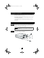
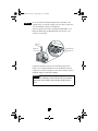
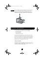
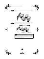
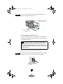
29160LPRevA.fm Page 14 Tuesday, May 2, 2000 4:04 PM
R
INSTALLATION
GUIDE
ADAPTEC SCSI CARD 29160LP
ULTRA160 SCSI CONTROLLER
29160LPRevA.fm Page 1 Tuesday, May 2, 2000 4:04 PM
INTRODUCTION
The Adaptec SCSI Card 29160LP Ultra160 SCSI controller
enables you to connect up to 15 SCSI devices—such as hard disk
drives, scanners, and CD-ROM drives—to any Intel-based
computer with 32-bit or 64-bit PCI expansion slots. You can
connect newer Ultra160 and Ultra2 SCSI devices to the two 68pin Low Voltage Differential/Single-Ended (LVD/SE) connectors.
CAUTION
If you connect singled-ended devices along with
Ultra160 or Ultra2 SCSI devices, the data transfer speed of
the Ultra160 or Ultra2 SCSI devices drops to the slower single-ended transfer rate. Although the Adaptec SCSI Card
29160LP is a 64-bit PCI card, it also works in a 32-bit PCI slot.
When installed in a 32-bit PCI slot, the card automatically
runs in the slower 32-bit mode.
68-pin Internal LVD/SE
connector
68-pin External VHDCI LVD/SE
connector
This installation guide explains how to:
• Install the Adaptec SCSI Card 29160LP
• Set up SCSI devices
• Connect SCSI devices
• Install Adaptec SCSI Card driver software
1
29160LPRevA.fm Page 2 Tuesday, May 2, 2000 4:04 PM
CHANGING
THE
CHANGING
BRACKET
THE
BRACKET
The Adaptec SCSI Card 29160LP chips have a bracket designed to
fit in low-profile rack-mount server.
If you plan to use this card in a standard-height system, you will
need to change the bracket.
See the Adaptec SCSI Card 29160LP Technical Reference for more
information.
INSTALLING THE ADAPTEC SCSI CARD 29160LP
STEP 1
Discharge any static electricity build-up before handling the SCSI
card by touching a grounded metal object (such as the exposed
metal parts on the back of your computer).
WARNING Turn OFF power to the computer and disconnect
the power cord.
STEP 2
After you turn off your computer and unplug the power cord,
remove the cover from the computer.
2
29160LPRevA.fm Page 3 Tuesday, May 2, 2000 4:04 PM
STEP 3
Locate an unused 64-bit PCI expansion slot and remove the
expansion slot cover. If the computer does not have a 64-bit slot,
you can install the card in a 32-bit PCI slot.
Select an expansion slot that is compliant with PCI Rev. 2.1 or
higher, and that supports Bus Mastering. Save the slot cover
screw for use in Step 4.
Slot cover
screw
Expansion
slot cover
64-bit PCI slot
32-bit PCI slot
Computers may have vertical or horizontal expansion slots.
Refer to your computer manual to locate the PCI slots. If your
computer is a tower model, place it on its side to make it easier to
install the Adaptec SCSI Card 29160LP.
WARNING Be careful when inserting the Adaptec SCSI Card
29160LP into a PCI slot. Some 32-bit slots do not accommodate 64-bit cards, and the card or slot may break if you use
force.
3
29160LPRevA.fm Page 4 Tuesday, May 2, 2000 4:04 PM
STEP 4
Insert the Adaptec SCSI Card 29160LP into the PCI expansion
slot. Press down firmly until the card clicks into place; then
replace the slot cover screw. When installed properly, the card
should appear level with the expansion slot, as shown below.
SETTING UP SCSI DEVICES
You may need to do several things to your SCSI devices before
you connect them to the Adaptec SCSI Card 29160LP:
• Check the SCSI IDs.
• Set the termination.
• Connect the power cables.
Since setup can vary from device to device, always refer to the
documentation supplied with the device for specific instructions.
Below are some guidelines for setting SCSI IDs and termination
on your devices. Refer to the Adaptec SCSI Card 29160LP User’s
Reference for more information on these topics.
Check the SCSI IDs
The Adaptec SCSI Card 29160LP and each device you connect to
it must have a unique SCSI ID number ranging from 0 to 15. No
two devices can have the same number.
4
29160LPRevA.fm Page 5 Tuesday, May 2, 2000 4:04 PM
NOTE The Adaptec SCSI Card 29160LP is preset to SCSI ID 7
and should not be changed.
If you want to configure your computer to boot from a SCSI hard
disk, make sure the SCSI ID of that hard disk is set to 0. Most
SCSI hard disks are preset to SCSI ID 0 at the factory. The SCSI
IDs for internal devices are usually set with jumpers; SCSI IDs for
external devices are usually set with a switch on the back of the
device.
Terminate the Ends of the SCSI Bus
To ensure reliable communication on the SCSI bus, the device at
the end of the cable, or the end of the cable itself, must have
proper termination installed (or enabled). Terminators must be
removed, or termination must be disabled, on devices between
the ends of each cable.
Terminate LVD (Ultra160 and Ultra2) SCSI Devices
LVD SCSI devices are automatically unterminated. If you have
internal LVD SCSI devices, a special 68-pin internal LVD cable is
required to connect the devices. Internal LVD cables usually have
an LVD or Auto switching terminator built into the end of the
cable. With this type of cable, it is not necessary to terminate
individual internal LVD SCSI devices. If your cable does not have
a terminator built in, you must add a terminator to the end of the
cable.
Mount the Devices
If you have internal SCSI devices, mount each device in an
available drive bay inside your computer, as shown below. Refer
to your computer and device documentation for instructions on
installing devices inside your computer.
5
29160LPRevA.fm Page 6 Tuesday, May 2, 2000 4:04 PM
Internal SCSI device
mounted in drive
bay
CONNECTING SCSI DEVICES
You can connect up to 15 SCSI devices to the Adaptec SCSI Card
29160LP. Before connecting devices, be sure to review Setting Up
SCSI Devices on page 4.
Connecting Internal SCSI Devices
Connect internal SCSI devices to the internal LVD/SE connector.
To do this, use a 68-pin internal LVD cable similar to the one
shown in Step 1 below. Follow these steps to connect the devices:
NOTE If you connect single-ended SCSI devices along with
Ultra160 or Ultra2 SCSI devices, the data transfer speed
drops to the slower single-ended rate.
STEP 1
Locate a 68-pin internal LVD SCSI cable, which has flat,
laminated wires, as shown below.
Terminated end
Nonterminated end
6
29160LPRevA.fm Page 7 Tuesday, May 2, 2000 4:04 PM
STEP 2
Plug the nonterminated end of the cable to the internal LVD/SE
connector.
STEP 3
Plug the internal devices to the other cable connectors, starting
with the connector at the terminated end of the cable.
Internal SCSI devices
Plug first device
to this connector
Built-in terminator
on cable
NOTE Internal Ultra2 and Ultra160 SCSI devices come from
the factory with termination disabled and cannot be changed.
Proper SCSI bus termination is provided by the terminator at
the end of the LVD SCSI cable.
7
29160LPRevA.fm Page 8 Tuesday, May 2, 2000 4:04 PM
STEP 4
Connect a power cable from your computer’s internal power
supply to each internal SCSI device.
Power cable (from the power
supply inside the com-
Power input connector
on the back of the
Connecting External SCSI Devices
Connect external SCSI devices to the 68-pin external VHDCI
LVD/SE SCSI connector. Each external device requires a 68-pin
external LVD SCSI cable.
NOTE We recommend that you connect only Ultra160 and
Ultra2 SCSI devices to the external SCSI connector. If you
also attach slower Ultra SCSI devices, the data transfer speed
of the Ultra160 and Ultra2 SCSI devices drops to the speed of
the slower devices.
Follow these steps to connect external SCSI devices:
STEP 1
Connect one end of the external LVD SCSI cable to the external
LVD/SE connector on the Adaptec SCSI Card 29160LP.
8
29160LPRevA.fm Page 9 Tuesday, May 2, 2000 4:04 PM
STEP 2
Connect the other end of the external SCSI cable to a SCSI
connector on the back of an external SCSI device.
SCSI Terminator
4
4
If you are installing only one external device, terminate the
device and skip to Step 4.
STEP 3
Connect other external devices by cabling each device to the
previous one, as shown below. Terminate only the device at the
end of the chain.
Not terminated
Terminated
STEP 4
Connect power cables to all external devices and to the computer.
9
29160LPRevA.fm Page 10 Tuesday, May 2, 2000 4:04 PM
STEP 5
Double-check for proper SCSI bus termination.
CAUTION Using a single-ended terminator will cause the SCSI
bus to run in single-ended mode. LVD termination must be
used to obtain Ultra2 transfer rates.
ADAPTEC SCSI CARD DRIVER SOFTWARE
To use the Adaptec SCSI Card 29160LP, the card’s driver software
must be installed for your operating system (for example,
Windows® 98, Windows 2000, Windows NT®, Novell NetWare,
and so forth). The Ultra160 Family Manager Set contains driver
software for many of the popular operating systems.
Refer to the Ultra160 Family Manager Set User’s Guide and
Adaptec SCSI Card 29160LP User’s Reference for instructions on
either installing driver software when installing your operating
system, or installing driver software when the operating system is
already installed.
NOTE Operating system versions released after November
1999, may have embedded driver support for the Adaptec
SCSI Card 29160LP. To determine if the card is supported by
the operating system you are using, read the operating system
manual or contact the operating system vendor for information. Visit Microsoft’s Web site <http://www.microsoft.com>
for more information regarding hardware compatibility.
10
29160LPRevA.fm Page 11 Tuesday, May 2, 2000 4:04 PM
TROUBLESHOOTING
If you have any problems while installing the Adaptec SCSI Card
29160LP, check the following items first:
• Are all SCSI devices powered on?
• Are all SCSI cables and power cables properly connected?
• Does each device on the SCSI bus have a unique SCSI ID?
• Does the total SCSI cable length exceed the maximum allowable length? See the Adaptec SCSI Card 29160LP User’s Guide
for more information about cable length limits.
• Is the SCSI bus properly terminated?
If you are still unable to resolve a problem, refer to the Adaptec
SCSI Card 29160LP User’s Reference, or the Adaptec Web site at
http://www.adaptec.com for additional troubleshooting
information.
11
29160LPRevA.fm Page 12 Tuesday, May 2, 2000 4:04 PM
Copyright
© 2000 Adaptec, Inc. All rights reserved. No part of this publication may be reproduced,
stored in a retrieval system, or transmitted in any form or by any means, electronic,
mechanical, photocopying, recording or otherwise, without the prior written consent of
Adaptec, Inc., 691 South Milpitas Blvd., Milpitas, CA 95035.
Trademarks
Adaptec, the Adaptec logo, and SpeedFlex are trademarks of Adaptec, Inc., which may
be registered in some jurisdictions. Windows 95, Windows 98, Windows NT, and
Windows 2000 are trademarks of Microsoft Corporation.
All other trademarks are the property of their respective owners.
Changes
The material in this document is for information only and is subject to change without
notice. While reasonable efforts have been made in the preparation of this document to
assure its accuracy, Adaptec, Inc. assumes no liability resulting from errors or omissions
in this document, or from the use of the information contained herein.
Adaptec reserves the right to make changes in the product design without reservation
and without notification to its users.
Disclaimer
IF THIS PRODUCT DIRECTS YOU TO COPY MATERIALS, YOU MUST HAVE
PERMISSION FROM THE COPYRIGHT OWNER OF THE MATERIALS TO AVOID
VIOLATING THE LAW WHICH COULD RESULT IN DAMAGES OR OTHER
REMEDIES.
12
29160LPRevA.fm Page 13 Tuesday, May 2, 2000 4:04 PM
Regulatory Compliance Statements
Federal Communications Commission Radio Frequency Interference Statement
WARNING: Changes or modifications to this unit not expressly approved by the party responsible for
compliance could void the user’s authority to operate the equipment.
This equipment has been tested and found to comply with the limits for a Class A digital device,
pursuant to Part 15 of the FCC rules. These limits are designed to provide reasonable protection
against harmful interference when the equipment is operated in a commercial environment. This
equipment generates, uses, and can radiate radio frequency energy, and if not installed and used in
accordance with the instruction manual, may cause harmful interference to radio communications.
Operation of this equipment in a residential area is likely to cause harmful interference in which case
the user will be required to correct the interference at his or her own expense.
This device complies with part 15 of the FCC rules. Operation is subject to the following two
conditions: (1) this device may not cause harmful interference and (2) this device must accept any
interference received, including interference that may cause undesired operation.
European Union Compliance Statement
This Information Technology Equipment has been tested and found to comply with the
following European directives:
EMC Directive 89/336/EEC
EN 50081-1 (1992)
EN55022 (1994) Class A
EN 50082-1 (1992)
EN61000-4-2 (1998)
EN61000-4-3 (1998)
EN61000-4-4 (1995)
Australian/New Zealand Compliance Statement
This device has been tested and found to comply with the limits for a Class A digital device,
pursuant to the Australian/New Zealand standard AS/NZS 3548 set out by the Spectrum
Management Agency.
Canadian Compliance Statement
This Class A digital apparatus meets all requirements of the Canadian Interference-Causing
Equipment Regulations.
Cet appareil numérique de la classe A respecte toutes les exigences du Règlement sur le
matérial brouilleur du Canada.
Japanese Compliance (Voluntary Control Council Initiative)
This is a class A product. In a domestic environment, this product may cause radio interference, in
which case the user may be required to take corrective action.
R
We move the information that
moves your world.™
© 2000 Adaptec, Inc. All rights reserved.
Printed in Singapore
Stock No.:512590-03, Rev. A, DR 04/2000
(SRC: 512590-00, Ver. AA)