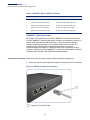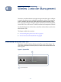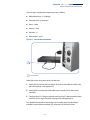
1
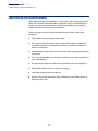
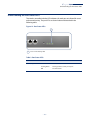
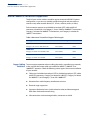
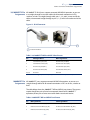
2-Port
Wireless Access Controller
EWS4502
I n s t a l l a ti o n G u i d e
www.edge-core.com
Installation Guide
EWS4502 Wireless Access Controller
with 2 1000BASE-T (RJ-45) Ports,
E062013-CS-R01
149100000238A
How to use This Guide
This guide includes detailed information on the wireless controller hardware,
including network ports, power, and cabling requirements. This guide also provides
general installation guidelines and recommended procedures. To deploy this
wireless controller effectively and ensure trouble-free operation, you should first
read the relevant sections in this guide so that you are familiar with all its hardware
components.
Who Should Read this This guide is for network administrators and support personnel that install, operate
Guide? and maintain network equipment. The guide assumes a basic working knowledge
of LANs (Local Area Networks) and can be read by those that are new to network
equipment, or those with more experience.
How this Guide is This organization of this guide is based on the wireless controller’s main hardware
Organized components. Each chapter includes information about a specific component with
relevant specifications and installation procedures. An overview section is also
provided.
For Users New to Wireless Controllers — If you are new to network equipment,
it is recommended that you first read all chapters in this guide before installing the
device.
For Experienced Users — If you are already familiar with installing and operating
network equipment, the Wireless Controller Overview and Installation Overview
chapters provide you with enough information to install the wireless controller.
Other chapters can be left for reference, when needed.
The guide includes these chapters:
◆
Chapter 1 - Wireless Controller Overview — Includes an introduction to the
wireless controller, key component identification, and key technical
specifications.
◆
Chapter 2 - Installation Overview — Includes information on the package
contents and an outline of wireless controller installation tasks.
◆
Chapter 3 - Wireless Controller Chassis — Includes chassis installaion for rack or
desktop, and system cooling requirements.
◆
Chapter 4 - Power and Grounding — Includes power connection information,
and grounding.
– 5 –
How to Use This Guide
◆
Chapter 5 - Port Connections — Includes information on network interfaces
and cabling specifications.
◆
Chapter 6 - Wireless Controller Management — Connecting to the wireless
controller for management, and information on the system status LEDs.
◆
Appendix A - Troubleshooting — Information for troubleshooting wireless
controller installation and operation.
Related This guide focuses on device hardware and installation, it does not cover software
Documentation configuration. For specific information on how to operate and use the
management functions of the wireless controller, see the following guides:
The CLI Command Reference
The Administrator’s Guide
For all safety information and regulatory statements, see the following document:
Safety and Regulatory Information
Conventions The following conventions are used throughout this guide to show information:
Note: Emphasizes important information or calls your attention to related features
or instructions.
Caution: Alerts you to a potential hazard that could cause loss of data, or damage
the system or equipment.
Warning: Alerts you to a potential hazard that could cause personal injury.
Revision History This section summarizes the changes in each revision of this guide.
June 2013 Revision
This is the first revision of this guide.
– 6 –
Contents
Warranty and Product Registration
4
How to use This Guide
5
Contents
7
Figures
9
Tables
10
1 Wireless Controller Overview
Introduction to the WAC4502 Wireless Access Controller
Key Hardware Components
Key Technical Specifications
2 Installation Overview
11
11
11
13
14
Package Contents
14
Overview of Installation Tasks
15
3 Wireless Controller Chassis
19
General Installation Guidelines
19
How to Install the Unit in a Rack
20
Rack-Mounting Items
20
Rack-Mount Procedure
20
Unit Cooling Requirements
22
Rack Cooling
22
4 Power and Grounding
23
AC Power Supply
23
Grounding the Chassis
24
How to Connect to AC Power
24
5 Port Connections
27
Cable Labeling and Connection Records
– 7 –
28
Contents
Understanding the Port Status LEDs
29
How to Connect to Twisted-Pair Copper Ports
30
Copper Cabling Guidelines
30
10/100BASE-TX Pin Assignments
31
1000BASE-T Pin Assignments
31
Connection Procedure
32
6 Wireless Controller Management
35
Understanding the System Status LEDs
35
How to Connect to the Console Port
36
A Troubleshooting
38
Diagnosing LED Indicators
38
System Self-Diagnostic Test Failure
38
Power and Cooling Problems
39
Installation
39
In-Band Access
39
Index
40
– 8 –
Figures
Figure 1: Front Panel
11
Figure 2: Rear Panel
12
Figure 3: Installing the Wireless Controller in a Rack
15
Figure 4: Connecting AC Power
16
Figure 5: System LEDs
16
Figure 6: Console Port
17
Figure 7: Making a Connection to an RJ-45 Port
18
Figure 8: Attaching the Brackets
21
Figure 9: Installing the Wireless Controller in a Rack
21
Figure 10: AC Power Socket
23
Figure 11: AC Power Socket
24
Figure 12: Port Status LEDs
29
Figure 13: RJ-45 Connector
31
Figure 14: Making Twisted-Pair Connections
32
Figure 15: System LEDs
35
Figure 16: Console Port
36
Figure 17: Console Port Connection
37
– 9 –
Tables
Table 1: Key Technical Specifications
13
Table 2: AC Power Supply Specifications
23
Table 3: Port Status LEDs
29
Table 4: Maximum Twisted-Pair Copper Cable Lengths
30
Table 5: 10/100BASE-TX MDI and MDI-X Port Pinouts
31
Table 6: 1000BASE-T MDI and MDI-X Port Pinouts
31
Table 7: System Status LEDs
36
Table 8: Console Cable Wiring
36
Table 9: Troubleshooting Chart
38
– 10 –
1
Wireless Controller Overview
This chapter includes these sections:
◆
“Introduction to the EWS4502 Wireless Access Controller” on page 11
◆
“Key Technical Specifications” on page 13
Introduction to the EWS4502 Wireless Access Controller
The EWS4502 wireless access controller is built with leading-edge technology to
deliver reliable high-performance connectivity for your data network.
The EWS4502 is an intelligent Layer 2 wireless controller designed for managing
access points in an enterprise-wide Wi-Fi network. The wireless controller provides
two 1000BASE-TX RJ-45 ports for wired connections to other network devices.
The wireless controller has one RJ-45 serial console port for out-of-band
management access. It also includes a management agent, which supports in-band
access using a Web browser, SNMP/RMON, or Telnet/SSH.
Key Hardware The EWS4502 wireless controller consists of serveral key harware components. This
Components manual describes each specific component, or related components, together with
their installation requirements and procedures in each chapter. To understand each
component in detail, refer to the relevant section.
Figure 1: Front Panel
1
4
2
3
1
1000BASE-T RJ-45 Ports
3
System and Port LEDs
2
Console Ports
4
Reset Button
– 11 –
Chapter 1 | Wireless Controller Overview
Introduction to the EWS4502 Wireless Access Controller
RJ-45 Ports
The wireless controller provides two 1000BASE-T RJ-45 ports for network
connections. For more information, see “How to Connect to Twisted-Pair Copper
Ports” on page 30.
System LEDs
For information on system status LED indicators, see “Understanding the System
Status LEDs” on page 35.
Port LEDs
For information on port status LED indicators, see “Understanding the Port Status
LEDs” on page 29.
Console Port
The RJ-45 port labeled “Console” provides an out-of-band serial connection to a
terminal or a PC running terminal emulation software. The port can be used for
performing wireless controller monitoring and configuration. For more
information, see “How to Connect to the Console Port” on page 36.
Reset Button
The Reset button can bu used to restart the unit or restore factory defaults. For
more information, see “How to Connect to the Console Port” on page 36.
Figure 2: Rear Panel
1
1
AC Power Socket
AC Power Socket
The AC power socket is used to connect the wireless controller to an AC power
source. For more information, see “How to Connect to AC Power” on page 24.
– 12 –
Chapter 1 | Wireless Controller Overview
Key Technical Specifications
Key Technical Specifications
The following table contains key system specifications for the wireless controller.
Table 1: Key Technical Specifications
Item
Specification
Ports
2 1000BASE-T RJ-45 ports
Network Interface
Ports 1~2: RJ-45 connector, auto MDI/X
10BASE-T: RJ-45 (100-ohm, UTP cable; Category 3 or better)
◆
100BASE-TX: RJ-45 (100-ohm, UTP cable; Category 5 or better)
◆
1000BASE-T: RJ-45 (100-ohm, UTP or STP cable; Category 5, 5e
or 6)
◆
Aggregate Bandwidth
4 Gbps
LEDs
System: Power/System
Ports 1~2: Status (link and activity)
Weight
2.1 kg (4.63 lb)
Size
W x D x H: 330 x 175 x 44 mm (12.99 x 6.89 x 1.73 inches)
Power
100~240V AC, 50~60Hz, 65 W
Temperature
Operating: 0 °C to 50 °C (32 °F to 122 °F)
Storage: -40 °C to 70 °C (-40 °F to 158 °F)
Humidity
Operating: 5% to 95% (non-condensing)
Out-of-Band Management
RS-232 RJ-45 console port
In-Band Management
SSH, Telnet, SNMP, or HTTP
Software Loading
HTTP, FTP/SFTP/TFTP, or SCP in-band
Throughput
Wire speed
– 13 –
2
Installation Overview
This chapter includes these sections:
◆
“Package Contents” on page 14
◆
“Overview of Installation Tasks” on page 15
Package Contents
After unpacking the wireless controller, check the contents to be sure you have
received all the items.
◆
EWS4502 Wireless LAN Controller
◆
Rack Mounting Kit containing two brackets and eight screws for attaching the
brackets to the wireless controller
◆
Power cord—either US, Continental Europe or UK
◆
Console cable (RJ-45 to DB-9)
◆
Quick Start Guide
◆
Regulatory and Safety Information
◆
Documentation CD — includes Installation Guide, Administrator’s Guide, and CLI
Command Reference
– 14 –
Chapter 2 | Installation Overview
Overview of Installation Tasks
Overview of Installation Tasks
Follow these tasks to install the wireless controller in your network. For full details
on each task, go to the relevant chapter or section by clicking on the link.
Note: Before installing your wireless controller, be sure to review all the safety
statements and guidelines in the Regulatory and Safety Information document.
Task 2
Install the Chassis
Plan your installation location and install the wireless controller chassis.
Go to the chapter “Wireless Controller Chassis”
Figure 3: Installing the Wireless Controller in a Rack
1
2
1
Attach the rack mounting brackets to the unit.
2
Use the rack mounting screws supplied with the rack to secure the wireless
controller in the rack.
– 15 –
Chapter 2 | Installation Overview
Overview of Installation Tasks
Task 3
Power On
Ground the wireless controller, then power on.
Go to the chapter “Power and Grounding”
Figure 4: Connecting AC Power
1
1
Task 4
Connect an external AC power source to the wireless controller.
Verify Wireless Controller Operation
Verify basic wireless controller operation by checking the system LEDs.
Go to the section “Understanding the System Status LEDs”
Figure 5: System LEDs
1
1
System Status LED.
– 16 –
Chapter 2 | Installation Overview
Overview of Installation Tasks
Task 5
Make Initial Configuration Changes
At this point you may need to make a few basic wireless controller configuration
changes before connecting to the network. It is suggested to connect to the
wireless controller console port to perform this task.
Go to “How to Connect to the Console Port”
Figure 6: Console Port
1
1
Console Port.
For information on initial wireless controller configuration:
Refer to the Administrator’s Guide.
Task 6
Connect Cables
Connect network cables to the wireless controller.
Go to the chapter “Port Connections”
– 17 –
Chapter 2 | Installation Overview
Overview of Installation Tasks
Figure 7: Making a Connection to an RJ-45 Port
1
1
Connect Category 5, 5e, 6 or better cable to the RJ-45 ports.
– 18 –
3
Wireless Controller Chassis
The wireless controller is designed to be installed in a standard 19-inch equipment
rack.
Before continuing with installation, first review the general guidelines and unit
cooling requirements in this chapter.
This chapter includes these sections:
◆
“General Installation Guidelines” on page 19
◆
“How to Install the Unit in a Rack” on page 20
◆
“Unit Cooling Requirements” on page 22
General Installation Guidelines
Be sure to follow the guidelines below when choosing a location.
◆
The installation location should:
■
be able to maintain its temperature within 0 to 40 °C (32 to 104 °F) and its
humidity within 5% to 95%, non-condensing.
■
provide adequate space (approximately five centimeters or two inches) on
all sides for proper air flow.
■
be accessible for installing, cabling and maintaining the device.
■
allow the status LEDs to be clearly visible.
◆
Make sure twisted-pair cable is always routed away from power lines,
fluorescent lighting fixtures and other sources of electrical interference, such as
radios and transmitters.
◆
Make sure that the unit is connected to a separate grounded power outlet and
is powered from an independent circuit breaker. As with any equipment, using
a filter or surge suppressor is recommended.
– 19 –
Chapter 3 | Wireless Controller Chassis
How to Install the Unit in a Rack
How to Install the Unit in a Rack
When rack mounting the wireless controller, pay particular attention to the
following factors:
◆
Rack Types: You can use any standard EIA 19-inch equipment rack with either
two or four posts. The bracket hole pattern should be spaced 1U (1.75 in. or
4.45 cm) apart.
◆
Rack Stability: Whenever possible, secure the rack to the building ceiling or
floor, particularly if you are located in a region where earthquakes are common.
◆
Rack Planning: When installing equipment in a rack, first plan how units can
be best arranged. Try to always mount the heaviest equipment at the bottom
of the rack.
◆
Temperature: Since the temperature within a rack assembly may be higher
than the ambient room temperature, check that the rack-environment
temperature is within the specified operating temperature range. See “Unit
Cooling Requirements” on page 22.
◆
Mechanical Loading: Do not place any equipment on top of a rack-mounted
unit.
◆
Circuit Overloading: Be sure that the supply circuit to the rack assembly is not
overloaded.
◆
Grounding: Rack-mounted equipment should be properly grounded.
Rack-Mounting Items Before you start to rack-mount the wireless controller, be sure to have the following
items available:
◆
Four mounting screws for each device you plan to install in a rack—these are
not included. Be sure to use the rack mounting screws that are supplied with
the rack.
◆
A screwdriver (Phillips or flathead, depending on the type of screws used).
Rack-Mount To rack mount the wireless controller, follow these steps:
Procedure
1. Attach the brackets to the device using the screws provided in the Rack
Mounting Kit.
– 20 –
Chapter 3 | Wireless Controller Chassis
How to Install the Unit in a Rack
Figure 8: Attaching the Brackets
1
1
Use the screws included in the rack
mounting kit.
2. Following your rack plan, mark the holes in the rack where the wireless
controller will be installed.
3. Lift the wireless controller into the rack so that it is aligned with the marked
holes.
4. Secure the wireless controller in the rack, using four rack-mounting screws (not
provided).
Figure 9: Installing the Wireless Controller in a Rack
1
1
Use the rack mounting screws supplied
with the rack.
– 21 –
Chapter 3 | Wireless Controller Chassis
Unit Cooling Requirements
5. If installing a single wireless controller only, go to “Power and Grounding” on
page 23.
6. If installing multiple wireless controllers, repeat steps 1 to 4 to mount the units
following your rack plan.
Unit Cooling Requirements
Wherever the wireless controller is located, be sure to pay close attention to
cooling requirements. The location should be well ventilated and provide
unrestricted air flow at the front, back, and sides of the wireless controller. If the air
flow is insufficient, it may cause the wireless controller to overheat and possibly fail.
Rack Cooling When mounting the wireless controller in an enclosed rack or cabinet, be sure to
check the following guidelines to prevent overheating:
◆
Make sure that enough cool air can flow into the enclosure for the equipment it
contains.
◆
Check that the rack or cabinet allows the hot air to exit the enclosure (normally
from the top) without circulating back into equipment.
◆
If the enclosure has sides or doors with ventilation holes, make sure they are
not blocked by cables or other obstructions.
◆
Route cables within the rack or cabinet to maximize the air flow.
◆
When possible, do not completely fill the rack or cabinet with equipment, allow
some unused space within the enclosure for better air flow.
– 22 –
4
Power and Grounding
This chapter focuses on the wireless controller power and how to power-on the
unit. Connecting the wireless controller to ground is also covered.
This chapter includes these sections:
◆
“AC Power Supply” on page 23
◆
“Grounding the Chassis” on page 24
◆
“How to Connect to AC Power” on page 24
AC Power Supply
The wireless controller requires power from an external AC power supply that
meets the specifications outlined in Table 2. A standard AC power socket is located
on the rear panel of the wireless controller, which is for the AC power cord.
Figure 10: AC Power Socket
1
1
AC Power Socket
Table 2: AC Power Supply Specifications
Item
Description
AC Input
100-240 VAC, 50-60 Hz, 6A
Power Consumption
60 Watts maximum
Maximum Current
2 A @ 100 VAC
1 A @ 240 VAC
– 23 –
Chapter 4 | Power and Grounding
Grounding the Chassis
Grounding the Chassis
The wireless controller chassis must be connected to ground to ensure proper
operation and to meet electromagnetic interference (EMI) and safety requirements.
The wireless controller chassis is connected internally to 0 V, which is then
grounded when it is connected to a grounded AC power outlet by an AC power
cord.
There are no grounding points on the wireless controller that require a connection
to a rack ground or other earth ground.
How to Connect to AC Power
The wireless controller does not have an on/off switch. The wireless controller is
powered on by connecting the unit to an AC power source.
To connect the wireless controller to an AC power source:
1. First verify that the external AC power meet the requirements in Table 2.
2. Plug the power cable into a grounded, 3-pin, AC power source.
Note: For international use, you may need to change the AC line cord. You must
use a line cord set that has been approved for the socket type in your country.
3. Insert the plug on the other end of the power cable directly into the socket on
the wireless controller.
Figure 11: AC Power Socket
1
2
1
2
AC Power Socket
– 24 –
AC Power Cord
Chapter 4 | Power and Grounding
How to Connect to AC Power
4. Check the indicators on the wireless controller as the unit is powered on to
verify that the Power LED is on. If not, recheck the power supply and power
cable connections at the supply source and at power module.
– 25 –
Chapter 4 | Power and Grounding
How to Connect to AC Power
– 26 –
5
Port Connections
This chapter focuses on making connections to the wireless controller’s network
interfaces, including details on network cable specifications.
The wireless controller features two 1000BASE-T RJ-45 ports for network
connections. The sections that follow describe these interfaces.
This chapter includes these sections:
◆
“Cable Labeling and Connection Records” on page 28
◆
“Understanding the Port Status LEDs” on page 29
◆
“How to Connect to Twisted-Pair Copper Ports” on page 30
– 27 –
Chapter 5 | Port Connections
Cable Labeling and Connection Records
Cable Labeling and Connection Records
When planning a network installation, it is essential to label the opposing ends of
cables and to record where each cable is connected. Doing so will enable you to
easily locate inter-connected devices, isolate faults and change your topology
without need for unnecessary time consumption.
To best manage the physical implementations of your network, follow these
guidelines:
◆
Clearly label the opposing ends of each cable.
◆
Using your building’s floor plans, draw a map of the location of all networkconnected equipment. For each piece of equipment, identify the devices to
which it is connected.
◆
Note the length of each cable and the maximum cable length supported by the
switch ports.
◆
For ease of understanding, use a location-based key when assigning prefixes to
your cable labeling.
◆
Use sequential numbers for cables that originate from the same equipment.
◆
Differentiate between racks by naming accordingly.
◆
Label each separate piece of equipment.
◆
Display a copy of your equipment map, including keys to all abbreviations at
each equipment rack.
– 28 –
Chapter 5 | Port Connections
Understanding the Port Status LEDs
Understanding the Port Status LEDs
The wireless controller includes LED indicators for each port to indicate link status
and network activity. The port LEDs are shown below and described in the
following table.
Figure 12: Port Status LEDs
1
1
Port 1-2 Link/Activity LEDs
Table 3: Port Status LEDs
LED
Condition
Status
Link/Activity
Green
Port has a valid link.
Flashing Green
Flashing indicates activity on the port.
Off
The link is down.
– 29 –
Chapter 5 | Port Connections
How to Connect to Twisted-Pair Copper Ports
How to Connect to Twisted-Pair Copper Ports
The RJ-45 ports on the wireless controller support automatic MDI/MDI-X pinout
configuration, so you can use standard straight-through twisted-pair cables to
connect to any other network device (PCs, servers, switches, routers, or hubs).
Each connection requires an unshielded twisted-pair (UTP) cable with RJ-45
connectors at both ends. Use Category 5, 5e or 6 cable for 1000BASE-T connections,
Category 5 or better for 100BASE-TX connections, and Category 3 or better for
10BASE-T connections.
Table 4: Maximum Twisted-Pair Copper Cable Lengths
Cable Type
Maximum Cable Length
Connector
100 m (328 ft)
RJ-45
100 m (328 ft)
RJ-45
100 m (328 ft)
RJ-45
1000BASE-T
Category 5, 5e, or 6 100-ohm UTP or STP
100BASE-TX
Category 5 or better 100-ohm UTP or STP
10BASE-T
Category 3 or better 100-ohm UTP
Copper Cabling To ensure proper operation when installing the wireless controller into a network,
Guidelines make sure that the current cables are suitable for 10BASE-T, 100BASE-TX or
1000BASE-T operation. Check the following criteria against the current installation
of your network:
◆
Cable type: Unshielded twisted pair (UTP) or shielded twisted pair (STP) cables
with RJ-45 connectors; Category 3 or better for 10BASE-T, Category 5 or better
for 100BASE-TX, and Category 5, 5e or 6 for 1000BASE-T.
◆
Protection from radio frequency interference emissions
◆
Electrical surge suppression
◆
Separation of electrical wires (switch related or other) and electromagnetic
fields from data based network wiring
◆
Safe connections with no damaged cables, connectors or shields
– 30 –
Chapter 5 | Port Connections
How to Connect to Twisted-Pair Copper Ports
10/100BASE-TX Pin All 100BASE-TX RJ-45 ports support automatic MDI/MDI-X operation, so you can
Assignments use straight-through or crossover cables for all network connections to PCs,
switches, or hubs. In straight-through cable, pins 1, 2, 3, and 6, at one end of the
cable, are connected straight through to pins 1, 2, 3, and 6 at the other end of the
cable.
Figure 13: RJ-45 Connector
1
1
RJ-45 Pin Numbers.
Table 5: 10/100BASE-TX MDI and MDI-X Port Pinouts
Pin
MDI Signal Namea
MDI-X Signal Name
1
Transmit Data plus (TD+)
Receive Data plus (RD+)
2
Transmit Data minus (TD-)
Receive Data minus (RD-)
3
Receive Data plus (RD+)
Transmit Data plus (TD+)
6
Receive Data minus (RD-)
Transmit Data minus (TD-)
4,5,7,8
Not used
Not used
a.
The “+” and “-” signs represent the polarity of the wires that make up each wire pair.
1000BASE-T Pin All 1000BASE-T ports support automatic MDI/MDI-X operation, so you can use
Assignments straight-through cables for all network connections to PCs or servers, switches or
hubs.
The table below shows the 1000BASE-T MDI and MDI-X port pinouts. These ports
require that all four pairs of wires be connected. Note that for 1000BASE-T
operation, all four pairs of wires are used for both transmit and receive.
Table 6: 1000BASE-T MDI and MDI-X Port Pinouts
Pin
MDI Signal Name
MDI-X Signal Name
1
Bi-directional Pair A Plus (BI_DA+)
Bi-directional Pair B Plus (BI_DB+)
2
Bi-directional Pair A Minus (BI_DA-)
Bi-directional Pair B Minus (BI_DB-)
3
Bi-directional Pair B Plus (BI_DB+)
Bi-directional Pair A Plus (BI_DA+)
– 31 –
Chapter 5 | Port Connections
How to Connect to Twisted-Pair Copper Ports
Table 6: 1000BASE-T MDI and MDI-X Port Pinouts
Pin
MDI Signal Name
MDI-X Signal Name
4
Bi-directional Pair C Plus (BI_DC+)
Bi-directional Pair D Plus (BI_DD+)
5
Bi-directional Pair C Minus (BI_DC-)
Bi-directional Pair D Minus (BI_DD-)
6
Bi-directional Pair B Minus (BI_DB-)
Bi-directional Pair A Minus (BI_DA-)
7
Bi-directional Pair D Plus (BI_DD+)
Bi-directional Pair C Plus (BI_DC+)
8
Bi-directional Pair D Minus (BI_DD-)
Bi-directional Pair C Minus (BI_DC-)
1000BASE-T Cable Requirements
All Category 5 UTP cables that are used for 100BASE-TX connections should also
work for 1000BASE-T, providing that all four wire pairs are connected. However, it is
recommended that for all critical connections, or any new cable installations,
Category 5e (enhanced Category 5) or Category 6 cable should be used. The
Category 5e and 6 specifications include test parameters that are only
recommendations for Category 5. Therefore, the first step in preparing existing
Category 5 cabling for running 1000BASE-T is a simple test of the cable installation
to be sure that it complies with the IEEE 802.3-2008 standards.
Connection Procedure Follow these steps to connect cables to RJ-45 twisted-pair copper ports.
1. Attach one end of a twisted-pair cable segment to the device’s RJ-45 connector.
Figure 14: Making Twisted-Pair Connections
1
1
Category 5, 5e or 6 UTP Cable
– 32 –
Chapter 5 | Port Connections
How to Connect to Twisted-Pair Copper Ports
2. Attach the other end to an available port on the wireless controller.
Make sure each twisted pair cable does not exceed 100 meters (328 ft) in
length.
3. As each connection is made, the Link LED (on the wireless controller)
corresponding to each port will turn on green to indicate that the connection is
valid.
– 33 –
Chapter 5 | Port Connections
How to Connect to Twisted-Pair Copper Ports
– 34 –
6
Wireless Controller Management
The wireless controller includes a management agent that allows you to configure
or monitor the device using its embedded management software. To manage the
wireless controller, you can make a direct connection to the console port (out-ofband), or you can manage it through a network connection (in-band) using Telnet,
Secure Shell (SSH), a web browser, or SNMP-based network management software.
For a detailed description of the wireless controller’s software features, refer to the
Administrator’s Guide.
This chapter includes these sections:
◆
“Understanding the System Status LEDs” on page 35
◆
“How to Connect to the Console Port” on page 36
Understanding the System Status LEDs
The wireless controller includes a display panel of key system LED indicators. The
LEDs, which are located on the front panel, are shown below and described in the
following table.
Figure 15: System LEDs
1
1
System Status LED
– 35 –
Chapter 6 | Wireless Controller Management
How to Connect to the Console Port
Table 7: System Status LEDs
LED
Condition
Status
Pwr/Sys
On Green
System is receiving power and running normally.
On Yellow
System self-diagnostic test has detected a fault.
Off
The system is not receiving power.
How to Connect to the Console Port
The RJ-45 Console port on the wireless controller’s front panel is used to connect to
the unit for out-of-band console configuration. The console device can be a PC or
workstation running a VT-100 terminal emulator, or a VT-100 terminal. An RJ-45-toDB-9 cable is supplied with the wireless controller for connecting to a PC’s RS-232
serial DB-9 DTE (COM) port.
Note: To connect to notebooks or other PCs that do not have a DB-9 COM port, use
a USB to male DB-9 adapter cable (not included with the wireless controller).
Figure 16: Console Port
1
1
Console Port
The following table describes the pin assignments used in the RJ-45-to-DB-9
console cable.
Table 8: Console Cable Wiring
Switch’s 8-Pin
Console Port
Null Modem
PC’s 9-Pin
DTE Port
6 RXD (receive data)
<---------------------
3 TXD (transmit data)
3 TXD (transmit data)
--------------------->
2 RXD (receive data)
5 SGND (signal ground)
-----------------------
5 SGND (signal ground)
No other pins are used.
– 36 –
Chapter 6 | Wireless Controller Management
How to Connect to the Console Port
The serial port’s configuration requirements are as follows:
◆
Default Baud rate—115,200 bps
◆
Character Size—8 Characters
◆
Parity—None
◆
Stop bit—One
◆
Data bits—8
◆
Flow control—none
Figure 17: Console Port Connection
1
1
Console Cable
Follow these steps to connect to the Console port:
1. Attach the DB-9 end of the included RJ-45-to-DB-9 serial cable to a DB-9 COM
port connector on a management PC.
2. Attach the RJ-45 end of the serial cable to the Console port on the wireless
controller.
3. Configure the PC’s COM port required settings using VT-100 terminal emulator
software (such as HyperTerminal) running on the management PC.
For a detailed description of connecting to the console and using the wireless
controller’s command line interface (CLI), refer to the CLI Reference Guide.
– 37 –
A
Troubleshooting
Diagnosing LED Indicators
Table 9: Troubleshooting Chart
Symptom
Action
Pwr/Sys LED is Off
◆
◆
Pwr/Sys LED is on Yellow
◆
◆
Link/Act LED is Off
◆
◆
◆
◆
Check connections between the PSU, the power cord and the wall
outlet.
Contact your dealer for assistance.
Power cycle the switch to try and clear the condition.
If the condition does not clear, contact your dealer for assistance.
Verify that the switch and attached device are powered on.
Be sure the cable is plugged into both the switch and
corresponding device.
Verify that the proper cable type is used and its length does not
exceed specified limits.
Check the attached device and cable connections for possible
defects. Replace the defective cable if necessary.
System Self-Diagnostic Test Failure
If the Pwr/Sys LED indicates a failure of the system power-on-self-test (POST), you
can use a console connection to view the POST results. The POST results may
indicate a failed component or help troubleshoot the problem. For more
information on connecting to the console port and using the CLI, refer to the CLI
Reference Guide.
Note a POST failure normally indicates a serious hardware fault that cannot be
rectified or worked around. If you encounter a POST failure, you should contact
your dealer for assistance.
– 38 –
Appendix A | Troubleshooting
Power and Cooling Problems
Power and Cooling Problems
If the power indicator does not turn on when the power cord is plugged in, you
may have a problem with the power outlet, power cord, or power supply unit.
However, if the unit powers off after running for a while, check for loose power
connections, power losses or surges at the power outlet. If you still cannot isolate
the problem, the power supply unit may be defective.
Installation
Verify that all system components have been properly installed. If one or more
components appear to be malfunctioning (such as the power cord or network
cabling), test them in an alternate environment where you are sure that all the
other components are functioning properly.
In-Band Access
You can access the management agent in the wireless controller through a
connection to any port using Telnet, a web browser, or other network management
software tools. However, you must first configure the wireless controller with a valid
IP address, subnet mask, and default gateway. If you have trouble establishing a
link to the management agent, check to see if you have a valid network connection.
Then verify that you entered the correct IP address. Also, be sure the wireless
controller port has not been disabled. If it has not been disabled, then check the
network cabling that runs between your remote location and the wireless
controller.
– 39 –
Index
Numerics
location requirements 19
10/100 PIN assignments 31
1000BASE-T PIN assignments 31
M
A
airflow requirements 19
B
brackets, attaching 21
buffer size 13
management
out-of-band 35
web-based 35
O
out-of-band management 35
P
C
cable
Ethernet cable compatibility 30
labeling and connection records 28
console port
pin assignments 36
console port, pin assignments 36
contents of package 14
cord sets, international 24
D
diagnosing LED indicators 38
E
electrical interference, avoiding 19
equipment checklist 14
package contents 14
pin assignments
console port 36
power
AC supply 23
power and cooling problems 39
power socket 23
S
screws for rack mounting 20
site selelction 19
specifications
environmental 13
status LEDs 29, 35
surge suppressor, using 19
W
web-based management 35
I
in-band access 39
indicators, LED 29, 35
installation
power requirements 19
site requirements 19
installation troubleshooting 39
introduction 11, 14
L
LED indicators
port 29
– 40 –
Declaration of Conformity (DoC) can be obtained from www.edge-core.com -> support -> download -> declarations & certifications
EWS4502
E062013-CS-R01
149100000238A