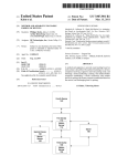
1
US008443406B2
(12) United States Patent
(10) Patent N0.:
(45) Date of Patent:
Reed et a].
(54)
ETHERNET OVER COAXIAL COUPLING
(56)
US 8,443,406 B2
May 14, 2013
References Cited
SYSTEM, METHOD AND APPARATUS
U.S. PATENT DOCUMENTS
(75)
Inventors: Vernon Reed, Austin, TX (US); Ahmad
C. Ansari, Cedar Park, TX (US); David
Rackley, Austin, TX (US)
5,355,096 A *
2005/0289632 A1*
10/1994
12/2005
2006/0010481 A1
2006/0225119 A1
1/2006 Wall et al.
10/2006 Wollmershauser et al.
2008/0018413 A1*
(73) Assignee: AT&T Intellectual Property I, L.P.,
Atlanta, GA (US)
Notice:
Subject to any disclaimer, the term of this
patent is extended or adjusted under 35
(74) Attorney, Agent, orFirm * Guntin & Gust, PLC; Jay H.
Anderson
Dec. 2, 2008
(65)
(57)
ABSTRACT
A device that incorporates teachings of the present disclosure
may include, for example, a controller to provide loW loss
Prior Publication Data
US 2010/0138880 A1
* cited by examiner
Primary Examiner * Vivek Srivastava
Assistant Examiner * Rong Le
(21) Appl. No.: 12/326,666
Filed:
Strull et al. ................. .. 333/132
OTHER PUBLICATIONS
CTC union technologies co.,Ltd, EOC-20/2l user manual, Sep.
2008,Ver.0.9, sections: 1, 10.2, 10.3, 104*
U.S.C. 154(b) by 719 days.
(22)
1/2008
Kobayashi .................. .. 330/278
Brooks et al. ............... .. 725/126
connectivity to a plurality of coaxial ports over a broadband
Jun. 3, 2010
range of frequencies in a coaxial network providing Ethernet
networking, detune secondary coaxial splitters in the coaxial
(51)
Int. Cl.
netWork that reduces an output-to-output isolation loss
H04N 7/18
(52)
US. Cl.
USPC
(58)
among secondary coaxial splitter output ports, and enable
re-distribution of modulated radio frequency video signals
(2006.01)
.......................................................... ..
725/78
Field of Classi?cation Search ..................... .. None
from a point on the coaxial netWork to any alternative point on
the coaxial netWork. Other embodiments are disclosed.
See application ?le for complete search history.
18 Claims, 5 Drawing Sheets
602
Ethernet
Over-Coax
Low toss
spimar
f612
i ' Low loss palh
608
Broadband Gateway"
Router
0O
I07
US. Patent
May 14, 2013
Sheet 1 of5
US 8,443,406 B2
130
L ACCESS NETWORK
Satellite
receiver m
dish
Y
g N-
-
ISP Ntwk Q <—,
Cable TV
133
Services
US. Patent
May 14, 2013
Sheet 2 of5
PORTAL
US 8,443,406 B2
/‘ 202
http://wwwmyportaLoom/
I
DVR
I I IMS Services I
I VoD Catalog I Ilnternet ServicesI
I
EPG
I ICollphone ServicesI
O
:
~"..I~'|.
20o
“““““
2
:=-::
Media
Processor
Communication Devices
Keypad M
‘q "5'
‘.:
Transceiver E
Location
Receiver l
Display 31_()
Controller @
Audio System w
Image sensor m
E
4
4
A
FIG. 3
I
I
I
Power Supply M
@
US. Patent
May 14, 2013
Sheet 3 of5
US 8,443,406 B2
Purposely creating a port
impedance mismatch in a
splitter for improved Ethernet
Detuning any secondary
networking over coaxial cables
in a coaxial network, wherein
the port impedance mismatch
causes a slightly lower power
V
transfer to each leg of the
splitter and a higher return loss
figure (as long as the return
loss figure is maintained under
splitter coupled to the coaxial
network, wherein the detuning
of any secondary splitter
results in reduced output port
isolation among output ports in
the secondary splitter
@
tOdB)
49g
Devices coupled to the
"
secondary splitter output ports
Enabling distribution of
observe less path loss
modulated radio frequency
between them enabling
video over the coaxial network
Ethernet over Coaxial cable
4
to deliver analog video to a
technologies to operate with a
higher data rate or improved
signal-to-noise ratio or both
plurality of repeater devices
coupled to the coaxial network
§_0_6
51%
Supporting connection of radio
frequency modulated video
Maintaining low loss at higher
frequency ranges by using
sources onto the coaxial cable
bypass capacitors at each
network enabling-re
distribution of analog television
signals to other locations
within a premise over the
coaxial cable network
iL
resistor in the splitter or
'
secondary splitter to establish
a flat or custom frequency
response profile
M
gm
FIG. 4
US. Patent
May 14, 2013
Sheet 4 of5
US 8,443,406 B2
Processor
Video
_
=
>
<
7
Display
Instructions -—\
E
m
524
Main Memory
Alpha-Numeric
4
>
Instructions r~\
M
<
Input
'
Device 512
524
‘Static Memory
Instructions ~
Cursor Control
4
>
<
>
Device
51_4
\
524
Machine
Readable
Network
Interface
I
:
Medium
Device 2
u
//‘ Instructions
524
523
516
Q.
Network
_
Signal Generation
<
>
Device
5L
m
FIG. 5
US. Patent
May 14, 2013
U.
K
Sheet 5 of5
US 8,443,406 B2
U
r624
R}: Mlxlulateu fed, TV
c
1- n‘ W1
652E534;
620
Caax came
EOC-enabied
a m
Etherneitiakx‘e
4
r ‘3e
Ekhsmei
Over-Coax
Low was
sputter
3:55,.
W
K 61 2
" Low loss path
608
EihemekOv M2021
(E00; 5:494 \
.
"""""
Brcadband
.4, Gateway!
Route!’
@
FIG. 6
61 0
"
"
US 8,443,406 B2
1
2
ETHERNET OVER COAXIAL COUPLING
operating in a home coaxial network resulting in the detuning
of a secondary splitter coupled to the home coaxial network,
detuning a secondary splitter coupled to the coaxial network,
SYSTEM, METHOD AND APPARATUS
and enabling distribution of modulated video over the home
coaxial network to deliver analog video to a plurality of
repeater devices coupled to the home coaxial network.
Yet another embodiment of the present disclosure can
entail a device having a controller to provide low loss con
nectivity to a plurality of coaxial ports over a broadband range
of frequencies in a coaxial network providing Ethernet net
FIELD OF THE DISCLOSURE
The present disclosure relates generally to coupling
devices and more speci?cally to support an Ethemet-Over
Coax (EOC) technology coupling system, method, and
device.
working, detune secondary coaxial splitters in the coaxial
BACKGROUND
network that reduces an output-to-output isolation loss
among secondary coaxial splitter output ports, and enable
re-distribution of modulated radio frequency video signals
Coaxial splitters were implemented by cable companies as
a means of providing analog cable signals to multiple televi
sion units within a home. However, due to imperfections in a
from a point on the coaxial network to any alternative point on
cable plant or intermediate network elements, analog signals
the coaxial network.
Yet another embodiment of the present disclosure can
entail a device having a splitter providing low loss connec
tivity to a plurality of coaxial ports over a range of frequencies
in a coaxial network by having a port impedance mismatch
that causes a lower power transfer to each leg of the splitter
and a higher return loss relative to an impedance matched
splitter. The splitter can be constructed to detune a secondary
coaxial splitter when coupled in an Ethernet over coaxial
network and constructed to reduce an output-to-output isola
can “re?ect” from one coaxial path back onto an adjacent path
causing “Ghost TV images.” Because of the ghost image
problem, splitter designs have evolved to incorporate a high
signal isolation between their output ports to suppress the
20
signal re?ections (and ghost images).
The evolution of Internet Protocol (IP) networking tech
nologies today makes it possible to deliver video (as well as
voice and data) over these new networks, leveraging also the
ability to map packet-based data onto a variety of Ethernet
over Coax (EOC) network technologies (e.g., Home Phone
Line Network Assn., or HPNA; Multimedia over Coax Assn.,
or MoCA, or other similar competing solutions that permit
the use of existing coax to deliver IP-network data throughout
the home without rewiring). Unfortunately, use of the tradi
tional Cable-TV splitter devices as part of EOC networks can
severely impair achievable data rates between devices
attached to the output ports because of the high design isola
tion of the legacy home network design that utiliZes high
isolation splitters.
25
tion loss among secondary coaxial splitter output ports when
coupled in the Ethernet over coaxial network.
FIG. 1 depicts an illustrative embodiment of a ?rst com
munication system 100 for delivering media content. The
30
col Television (IPTV) broadcast media system. The IPTV
media system can include a super head-end of?ce (SHO) 110
with at least one super headend o?ice server (SHS) 111 which
receives media content from satellite and/or terrestrial com
35
BRIEF DESCRIPTION OF THE DRAWINGS
40
The VHS 114 can distribute multimedia broadcast pro
grams via an access network 118 to commercial and/or resi
acting with the communication system of FIG. 1;
FIG. 3 depicts an illustrative embodiment of a communi
dential buildings 102 housing a gateway 104 (such as a com
cation device utiliZed in the communication system of FIG. 1;
45
operating in portions of the communication system of FIG. 1;
FIG. 5 is a diagrammatic representation of a machine in the
form of a computer system within which a set of instructions,
when executed, may cause the machine to perform any one or
50
DETAILED DESCRIPTION
55
as coaxial or phone line wiring) or can operate over a common
60
the home coaxial network, and enabling distribution of modu
lated radio frequency video over the home coaxial network to
deliver analog video to a plurality of repeater devices coupled
tions for creating a port impedance mismatch in a splitter
108 such as computers or television sets managed in some
instances by a media controller 107 (such as an infrared or RF
remote control).
The gateway 104, the media processors 106, and media
devices 108 can utiliZe tethered interface technologies (such
method involving setting a port impedance mismatch in a
splitter for Ethernet networking over coaxial cables in a home
computer-readable storage medium having computer instruc
gateway 104 can use common communication technology to
distribute IP-based media signals to media processors 106
such as Set-Top Boxes (STBs) using an EOC technology
which in turn present broadcast channels to media devices
One embodiment of the present disclosure can entail a
to the home coaxial network.
Another embodiment of the present disclosure can entail a
mon residential or commercial gateway). The access network
118 can represent a group of digital subscriber line access
multiplexers (DSLAMs) located in a central o?ice or a ser
vice area interface that provide broadband services over opti
cal links or copper twisted pairs 119 to buildings 102. The
more of the methodologies discussed herein; and
FIG. 6 is an illustration of a system using a splitter having
a port impedance mismatch for Ethernet networking over
coaxial cables in accordance with the embodiments herein.
coaxial network, detuning any secondary splitter coupled to
video head-end o?ices (VH0) 112 according to a common
multicast communication protocol.
FIG. 2 depicts an illustrative embodiment of a portal inter
FIG. 4 depicts an illustrative embodiment of a method
munication systems. In the present context, media content
can represent audio content, moving image content such as
videos, still image content, or combinations thereof. The SHS
server 111 can forward packets associated with the media
content to video head-end servers (VHS) 114 via a network of
FIG. 1 depicts an illustrative embodiment of a communi
cation system;
communication system 100 can represent an Internet Proto
wireless access protocol. With these interfaces, unicast or
multicast IP communications can be invoked between the
media processors 106 and subsystems of the IPTV media
system for services such as video-on-demand (VoD), brows
ing an electronic programming guide (EPG), or other infra
65
structure services.
Some of the network elements of the IPTV media system
can be coupled to one or more computing devices 130 a
US 8,443,406 B2
4
3
portion of Which can operate as a Web server for providing
portal services over an Internet Service Provider (ISP) net
Work 132 to Wireline media devices 108 or Wireless commu
The UI 304 can include a depressible or touch-sensitive
keypad 3 08 With a navigation mechanism such as a roller ball,
joystick, mouse, or navigation disk for manipulating opera
nication devices 116 directly or indirectly by Way of a Wire
less access base station 117 operating according to common
Wireless access protocols such as Wireless Fidelity (WiFi), or
tions of the communication device 300. The keypad 308 can
be an integral part of a housing assembly of the communica
tion device 300 or an independent device operably coupled
thereto by a tethered Wireline interface (such as a USB cable)
or a Wireless interface supporting for example Bluetooth. The
keypad 308 can represent a numeric dialing keypad com
cellular communication technologies (such as GSM, CDMA,
UMTS, WiMAX, Software De?ned Radio or SDR, and so
on).
monly used by phones, and/or a Qwerty keypad With alpha
It Will be appreciated by an artisan of ordinary skill in the
place of the IPTV media system. In this embodiment, signals
numeric keys. The UI 304 can further include a display 310
such as monochrome or color LCD (Liquid Crystal Display),
transmitted by a satellite 115 supplying media content can be
intercepted by a common satellite dish receiver 131 coupled
play technology for conveying images to an end user of the
to the building 102. Modulated signals intercepted by the
communication device 300. In an embodiment Where the
satellite dish receiver 131 can be submitted to the digital
display 310 is touch-sensitive, a portion or all of the keypad
308 can be presented by Way of the display.
art that a satellite broadcast television system can be used in
OLED (Organic Light Emitting Diode) or other suitable dis
media processors 106 for generating broadcast channels
Which can be presented at the media devices 108. The media
processors 106 can be equipped With a broadband port to the
ISP netWork 132 to enable infrastructure services such asVoD
and EPG described above.
The UI 304 can also include an audio system 312 that
20
utiliZes common audio technology for conveying loW volume
audio (such as audio heard only in the proximity of a human
ear) and high volume audio (such as speakerphone for hands
In yet another embodiment, an analog or digital broadcast
free operation). The audio system 312 can further include a
distribution system such as cable TV system 133 can be used
microphone for receiving audible signals of an end user. The
in place of the IPTV media system described above. In this
embodiment the cable TV system 133 can provide Internet,
telephony, and interactive media services under conditions
Where the ECO technology and cable or satellite service
frequency use does not overlap.
It folloWs from the above illustrations that the present
25 UI 304 can further include an image sensor 313 such as a
charged coupled device (CCD) camera for capturing still or
moving images.
The poWer supply 314 can utiliZe common poWer manage
ment technologies such as replaceable and rechargeable bat
30
disclosure can apply to any present or future interactive media
content services.
FIG. 2 depicts an illustrative embodiment of a portal 202
Which can operate from the computing devices 130 described
earlier of communication 100 illustrated in FIG. 1. The portal
202 can be used for managing services of communication
systems 100-200. The portal 202 can be accessed by a Uni
form Resource Locator (URL) With a common Internet
broWser such as Microsoft’s Internet ExplorerTM using an
Internet-capable communication device such as those
described for FIGS. 1-2. The portal 202 can be con?gured, for
communication device 300 to facilitate long-range or short
35
40
example, to access a media processor 106 and services man
aged thereby such as a Digital Video Recorder (DVR), a VoD
catalog, an EPG, a personal catalog (such as personal videos,
pictures, audio recordings, etc.) stored in the media processor,
provisioning IMS services described earlier, provisioning
Internet services, provisioning cellular phone services, and so
45
on.
FIG. 3 depicts an exemplary embodiment of a communi
cation device 300. Communication 300 can serve in Whole or 50
in part as an illustrative embodiment of the communication
devices of FIGS. 1-2. The communication device 300 can
comprise a Wireline and/or Wireless transceiver 302 (herein
transceiver 302), a user interface (UI) 304, a poWer supply
314, a location receiver 316, and a controller 306 for manag
ing operations thereof. The transceiver 302 can support short
55
60
associated storage memory such a Flash, ROM, RAM,
SRAM, DRAM or other storage technologies.
The communication device 300 can be adapted to perform
the functions of the media processor 106, the media devices
108, or the portable communication devices 116 of FIG. 1. It
Will be appreciated that the communication device 300 can
also represent other common devices that can operate in
communication systems 100 of FIG. 1 such as a gaming
console and a media player.
FIG. 4 depicts an illustrative method 400 that operates in
portions of the communication system of FIG. 1. Method 400
can begin With step 402 in Which the method purposely cre
ates a port impedance mismatch in a splitter for improved
Ethernet netWorking over coaxial cables in a coaxial netWork
under a 10 dB loss. The method 400 at 404 can detune any
secondary splitter coupled to the coaxial netWork Where the
detuning of any secondary splitter results in a reduced output
port isolation among output ports in the secondary splitter.
Note that the secondary splitters are assumed to be impedance
example, CDMA-lX, UMTS/HSDPA, GSM/GPRS, TDMA/
EDGE, EV/DO, WiMAX, SDR, and next generation cellular
TCPIP, VoIP, etc.), and combinations thereof.
location services such as navigation. The controller 306 can
utiliZe computing technologies such as a microprocessor, a
digital signal processor (DSP), and/ or a video processor With
such as a home coaxial netWork or a coaxial netWork in an
Bluetooth, WiFi, Digital Enhanced Cordless Telecommuni
Wireless communication technologies as they arise. The
transceiver 402 can also be adapted to support circuit
sWitched Wireline access technologies (such as PSTN),
packet-sWitched Wireline access technologies (such as
range portable applications. The location receiver 316 can
utiliZe common location technology such as a global posi
tioning system (GPS) receiver for identifying a location of the
communication device 100 based on signals generated by a
constellation of GPS satellites, thereby facilitating common
o?ice setting. The port impedance mismatch causes a slightly
loWer poWer transfer to each leg of the splitter and a higher
return loss ?gure. The return loss ?gure generally should be
range or long-range Wireless access technologies such as
cations (DECT), or cellular communication technologies,
just to mention a feW. Cellular technologies can include, for
teries, supply regulation technologies, and charging system
technologies for supplying energy to the components of the
65
matched to a coaxial cable at 75 Ohms for example and an
input to the splitter can be an IPTV or iTV input signal. At
406, the method can enable distribution of modulated radio
US 8,443,406 B2
5
6
frequency (RF) video over the home coaxial network to
deliver analog video to a plurality of repeater devices coupled
to the home coaxial network.
all terminations are impedance matched to the coax (in this
Devices coupled to the secondary splitter output ports
impedance of either higher or lower than 75 ohms (predeter
mined impedance match), the net effect is a slightly less
power transfer to each leg of the splitter, at the expense of
somewhat higher than desired return loss ?gure. However, the
observe less path loss between them enabling Ethernet over
Coaxial cable technologies to operate with a higher data rate
or improved signal-to-noise ratio or both at 408. Note that the
splitter can minimiZe splitter losses in all directions while
enable operations over the coaxial cable at frequencies up to
1 GigahertZ or higher. At 410, the splitter can support con
nection of radio frequency modulated video sources onto the
case RG-59 or RG-6 is at 75 ohms).
By purposely designing the splitter to represent a port
port mismatch this creates propagates through the coax to an
10
tional splitter is ‘detuned’ from its design optimum, resulting
coaxial cable network enabling re-distribution of analog tele
in reduced output port isolation in the output ports of the
vision signals to other locations within a home over the
coaxial cable network. The method 400 maintains low loss at
higher frequency ranges by using bypass capacitors at each
15
resistor in the splitter or secondary splitter to establish a ?at or
custom frequency response pro?le at 412.
get completely out ofhand (e.g., <10 dB).
20
without departing from the scope and spirit of the claims
described below. For example, the network is not limited to a
home coaxial network, but can be con?gured for use in of?ce
The embodiments herein further include a new coaxial 25
splitter design that will serve not only to minimize the point
to-point loss that affects all existing EOC technologies, but
also enables devices using these technologies to communi
30
where, and also permit the distribution of modulated RF
video on the coax network to deliver analog video to video
repeater devices (2 or more secondary televisions) throughout
the home, dwelling or building. This device performs all three
of these functions simultaneously once installed at the “Main
The splitter device can be designed to minimiZe splitter
losses in all directions, and also at frequencies up to approxi
mately 1 GHZ (or higher) in order to support connection of RF
modulated video sources onto the coax plant in a way that
or building scenarios and multi-dwelling units.
cate in all directions with minimal loss, to detune any second
ary splitter that may be hidden in the wall or attic or else
secondary splitter(s). Devices attached to the secondary split
ter outputs thereby observe less path loss between them,
making EOC technologies operate with higher rate or
improved signal to noise ratios (or both). This effect works
extremely well as long as return loss ?gures are not allowed to
Upon reviewing the aforementioned embodiments, it
would be evident to an artisan with ordinary skill in the art that
said embodiments can be modi?ed, reduced, or enhanced
embedded splitter which results in a mismatch at its input
port. As a result, the internal circuitry of a secondary conven
35
Home Splitter” location.
An impedance-matching purely resistive splitter is typi
cally designed based on the following formula:
permits re-distribution of the analog TV signal to other loca
tion is a premise (whether a home, o?ice, or other structure).
Maintaining low loss at higher frequency may be achieved
using bypass capacitors at each resistor to establish a ?at or
custom frequency response pro?le. Current test units have
demonstrated support for EOC and RF signals up to 1.5 GHZ.
Since most RF modulators provide output signal levels of + 1 5
to +23 dBmV, and television receivers expect to have signal
levels of at least —8 dBmV, the loss budget for the new splitter
is between 23 and 31 dB for good quality video distribution.
The splitter in accordance with the embodiments herein can
exhibit even in a 1:6 con?guration, losses in the 14 dB range
in a worst case scenario. This relatively low loss easily per
mits RF distribution even in quite large homes or buildings.
Other suitable modi?cations can be applied to the present
disclosure without departing from the scope of the claims
40
below. Accordingly, the reader is directed to the claims sec
tion for a fuller understanding of the breadth and scope of the
present disclosure.
FIG. 5 depicts an exemplary diagrammatic representation
where ZILoad Impedance (e. g., 75 ohms), and N:Total # of
splitter ports However, a purely resistive splitter which looks
like the following schematically:
45
of a machine in the form of a computer system 500 within
which a set of instructions, when executed, may cause the
machine to perform any one or more of the methodologies
discussed above. In some embodiments, the machine oper
2552
F-Connector
F-Connector
F-Connector
2552
Rint
These equations and schematics may be expanded to accom- 65 ates as a standalone device. In some embodiments, the
modate many additional port con?gurations (e.g., 1:3, 1:4,
1:5, 1 :6, etc.). Note however that the above example assumed
machine may be connected (e.g., using a network) to other
machines. In a networked deployment, the machine may
US 8,443,406 B2
8
7
While the machine-readable medium 522 is shown in an
operate in the capacity of a server or a client user machine in
server-client user network environment, or as a peer machine
example embodiment to be a single medium, the term
in a peer-to-peer (or distributed) network environment.
“machine-readable medium” should be taken to include a
single medium or multiple media (e.g., a centraliZed or dis
The machine may comprise a server computer, a client user
tributed database, and/or associated caches and servers) that
computer, a personal computer (PC), a tablet PC, a laptop
computer, a desktop computer, a control system, a network
store the one or more sets of instructions. The term “machine
router, switch or bridge, or any machine capable of executing
a set of instructions (sequential or otherwise) that specify
actions to be taken by that machine. It will be understood that
a device of the present disclosure includes broadly any elec
tronic device that provides voice, video or data communica
tion. Further, while a single machine is illustrated, the term
“machine” shall also be taken to include any collection of
machines that individually or jointly execute a set (or multiple
readable medium” shall also be taken to include any medium
sets) of instructions to perform any one or more of the meth
point-to-point loss that affects all existing EOC technologies,
that is capable of storing, encoding or carrying a set of instruc
tions for execution by the machine and that cause the machine
to perform any one or more of the methodologies of the
present disclosure.
FIG. 6 depicts an exemplary diagrammatic representation
of a system 600 in a premise 602 such as a home or o?ice
where the new coaxial splitter design as contemplated herein
in the form of splitter 608 can serve not only to minimize the
odologies discussed herein.
but also enables devices using these technologies to commu
nicate in all directions with minimal loss, to detune any sec
The computer system 500 may include a processor 502
(e.g., a central processing unit (CPU), a graphics processing
unit (GPU, or both), a main memory 504 and a static memory
506, which communicate with each other via a bus 508. The
computer system 500 may further include a video display unit
510 (e.g., a liquid crystal display (LCD), a ?at panel, a solid
state display, or a cathode ray tube (CRT)). The computer
system 500 may include an input device 512 (e.g., a key
ondary splitter such as secondary splitter 614 that may be
20
hidden in the wall or attic or elsewhere, and also permit the
distribution of modulated RF video on the coax network to
deliver analog video to video repeater devices (2 or more
secondary televisions such as TV 624) throughout the home,
dwelling or building.
25
board), a cursor control device 514 (e.g., a mouse), a disk
drive unit 516, a signal generation device 518 (e.g., a speaker
As illustrated, the system 600 can include a broadband
gateway or router 604 coupled to an EOC bridge 606 over an
tions (e.g., software 524) embodying any one or more of the
Ethernet cable. The bridge 606 feeds a signal to the EOC low
loss splitter 608 as contemplated in the embodiments herein.
The splitter 608 can have low loss paths in multiple directions
including a path to an EOC-enabled set top box (STB) or
digital video recorder 610 that is coupled to TV 612 or a path
methodologies or functions described herein, including those
to the secondary splitter 614. Since the secondary splitter 614
methods illustrated above. The instructions 524 may also
reside, completely or at least partially, within the main
memory 504, the static memory 506, and/or within the pro
is detuned as discussed above, other EOC-enabled devices
(such as EOC-enabled STE 616 and EOC-enabled Bridge
or remote control) and a network interface device 520.
The disk drive unit 516 may include a machine-readable
medium 522 on which is stored one or more sets of instruc
30
35
620 and their respective presentation devices 618 and 622)
cessor 502 during execution thereof by the computer system
will operate without signi?cant or perceptible detriment to
500. The main memory 504 and the processor 502 also may
constitute machine-readable media.
the end user.
The term “machine-readable medium” shall accordingly
be taken to include, but not be limited to: solid-state memories
Dedicated hardware implementations including, but not
limited to, application speci?c integrated circuits, program
40
such as a memory card or other package that houses one or
mable logic arrays and other hardware devices can likewise
be constructed to implement the methods described herein.
more read-only (non-volatile) memories, random access
memories, or other re-writable (volatile) memories; mag
Applications that may include the apparatus and systems of
various embodiments broadly include a variety of electronic
and computer systems. Some embodiments implement func
neto-optical or optical medium such as a disk or tape; and/or
a digital ?le attachment to e-mail or other self-contained
information archive or set of archives is considered a distri
45
bution medium equivalent to a tangible storage medium.
tions in two or more speci?c interconnected hardware mod
ules or devices with related control and data signals commu
nicated between and through the modules, or as portions of an
Accordingly, the disclosure is considered to include any one
or more of a machine-readable medium or a distribution
application-speci?c integrated circuit. Thus, the example sys
tem is applicable to software, ?rmware, and hardware imple
mentations.
In accordance with various embodiments of the present
disclosure, the methods described herein are intended for
operation as software programs running on a computer pro
cessor. Furthermore, software implementations can include,
but not limited to, distributed processing or component/ obj ect
50
implementations herein are stored.
Although the present speci?cation describes components
55
distributed processing, parallel processing, or virtual
machine processing can also be constructed to implement the
methods described herein.
The present disclosure contemplates a machine readable
medium containing instructions 524, or that which receives
and executes instructions 524 from a propagated signal so that
medium, as listed herein and including art-recognized
equivalents and successor media, in which the software
and functions implemented in the embodiments with refer
ence to particular standards and protocols, the disclosure is
not limited to such standards and protocols. Each of the
standards for Internet and other packet switched network
transmission (e.g., TCP/IP, UDP/IP, HTML, HTTP) represent
examples of the state of the art. Such standards are periodi
cally superseded by faster or more ef?cient equivalents hav
60
ing essentially the same functions. Accordingly, replacement
standards and protocols having the same functions are con
sidered equivalents.
a device connected to a network environment 526 can send or
The illustrations of embodiments described herein are
receive voice, video or data, and to communicate over the
intended to provide a general understanding of the structure
network 526 using the instructions 524. The instructions 524
may further be transmitted or received over a network 526 via
the network interface device 520.
65
of various embodiments, and they are not intended to serve as
a complete description of all the elements and features of
apparatus and systems that might make use of the structures
US 8,443,406 B2
9
10
described herein. Many other embodiments will be apparent
to those of skill in the art upon reviewing the above descrip
4. The method of claim 1, wherein the mismatch causes a
reduction in power transfer from an input port of the primary
splitter to the output port of the primary splitter and an
increase in return loss ?gure relative to the second impedance
tion. Other embodiments may be utilized and derived there
from, such that structural and logical substitutions and
changes may be made without departing from the scope of
this disclosure. Figures are also merely representational and
of the input port of the secondary splitter.
5. The method of claim 4, wherein the return loss ?gure is
maintained under 10 dB.
6. The method of claim 1, wherein devices coupled to the
may not be drawn to scale. Certain proportions thereof may
be exaggerated, while others may be minimized. Accord
ingly, the speci?cation and drawings are to be regarded in an
secondary splitter ?rst and second output ports observe less
illustrative rather than a restrictive sense.
path loss between them enabling Ethernet over Coaxial cable
technologies to operate with a higher data rate, improving
signal-to-noise ratios, or both.
7. The method of claim 1, wherein the primary splitter
reduces splitter losses in all directions while enabling opera
Such embodiments of the inventive subject matter may be
referred to herein, individually and/or collectively, by the
term “invention” merely for convenience and without intend
ing to voluntarily limit the scope of this application to any
single invention or inventive concept if more than one is in
fact disclosed. Thus, although speci?c embodiments have
been illustrated and described herein, it shouldbe appreciated
tions over the home coaxial network at frequencies up to 2
that any arrangement calculated to achieve the same purpose
8. The method of claim 7, wherein the primary splitter
supports connection of radio frequency modulated video
Giga-HertZ.
may be substituted for the speci?c embodiments shown. This
disclosure is intended to cover any and all adaptations or
20
variations of various embodiments. Combinations of the
above embodiments, and other embodiments not speci?cally
described herein, will be apparent to those of skill in the art
sources onto the home coaxial network enabling re-distribu
tion of analog television signals to other locations within a
home over the home coaxial network.
9. A non-transitory computer-readable storage medium,
comprising computer instructions which, when executed by
upon reviewing the above description.
The Abstract of the Disclosure is provided to comply with
37 C.F.R. §l .72(b), requiring an abstract that will allow the
reader to quickly ascertain the nature of the technical disclo
25 at least one processor, cause the at least one processor to
sure. It is submitted with the understanding that it will not be
used to interpret or limit the scope or meaning of the claims.
?rst impedance to cause a mismatch with a second
In addition, in the foregoing Detailed Description, it can be
perform operations for:
setting an output port impedance of a primary splitter to a
impedance of an input port of a secondary splitter and to
30
embodiment for the purpose of streamlining the disclosure.
This method of disclosure is not to be interpreted as re?ecting
an intention that the claimed embodiments require more fea
tures than are expressly recited in each claim. Rather, as the
cause an increased return loss and a reduced output port
isolation, wherein the primary splitter is coupled to the
secondary splitter by way of a home coaxial network,
seen that various features are grouped together in a single
and wherein the mismatch causes a reduction in signal
isolation between ?rst and second output ports of the
35
secondary splitter;
following claims re?ect, inventive subject matter lies in less
bypassing via a capacitor each resistor of a plurality of
than all features of a single disclosed embodiment. Thus the
resistors in the primary splitter and in the secondary
splitter; and
enabling from the primary splitter distribution of Ethernet
following claims are hereby incorporated into the Detailed
Description, with each claim standing on its own as a sepa
rately claimed subject matter.
40
What is claimed is:
1. A method, comprising:
setting an output port of a primary splitter to a ?rst imped
ance to cause a mismatch with a second impedance of an
input port of a secondary splitter and to cause an
increased return loss and a reduced output port isolation,
45
output ports.
10. A method, comprising:
causing output ports of a primary splitter to have an imped
wherein the primary splitter is coupled to the secondary
splitter by way of coaxial cables in a home coaxial
network;
detuning the secondary splitter coupled to the home
signals to devices coupled to the home coaxial network
by way of ?rst and second output ports of the secondary
splitter, wherein signal to noise ratios of the Ethernet
signals distributed from the ?rst and second output ports
of the secondary splitter are improved responsive to the
reduction in signal isolation between ?rst and second
50
coaxial network responsive to the mismatch thereby
ance mismatch with a plurality of coaxial input ports of
secondary splitters over a broadband range of frequen
cies in a coaxial network providing Ethernet networking
causing a reduction in a signal isolation between ?rst
and causing an increased return loss and a reduced out
and second output ports of the secondary splitter;
put port isolation;
detuning secondary splitters in the coaxial network respon
bypassing via a capacitor each resistor of a plurality of
resistors in the primary splitter and in the secondary
55
splitter to establish at least one of a ?at pro?le, a custom
secondary splitters;
pro?le, or a combination thereof; and
distributing from the primary splitter Ethernet signals over
the home coaxial network to devices coupled to the
home coaxial network by way of the ?rst and second
bypassing via a capacitor each resistor of a plurality of
60
output ports of the secondary splitter.
2. The method of claim 1, wherein the secondary splitter is
3. The method of claim 2, wherein the secondary splitter is
impedance matched to a coaxial cable at 75 Ohms and the
as Ethernet signals over the home coaxial network.
resistors in the primary splitter and in the secondary
splitter; and
distributing Ethernet signals from the output ports of the
secondary splitters responsive to the detuning of the
secondary splitters.
impedance matched to a coaxial cable.
primary splitter receives as an input a media signal distributed
sive to the impedance mismatch thereby reducing an
output-to-output isolation loss among output ports of the
65
11. The method of claim 10, wherein the broadband range
of frequencies is from DC. to 2 Giga-HertZ, and wherein the
coaxial input ports of the secondary splitters are matched to a
coaxial cable at 75 Ohms.
US 8,443,406 B2
11
12
port of the primary splitter to an output port of the
primary splitter and a higher return loss ?gure relative to
12. The method of claim 10, wherein the mismatch causes
a lower power transfer from an input port of the primary
the input impedance of the secondary splitter, wherein
splitter to the output ports of the primary splitter and a higher
return loss ?gure.
13. The method of claim 12, wherein the primary splitter
supports transmission of radio frequency modulated video
sources onto the coaxial cable network enabling re-distribu
tion of analog television signals to other locations within a
home over the coaxial cable network.
14. The method of claim 1 0, wherein devices coupled to the
10
output ports of the secondary splitters observe less path loss
between them enabling Ethernet over Coaxial cable technolo
gies to operate with a higher data rate or improved signal-to
noise ratio or both as long as the return loss ?gure is main
tained under 10 dB.
tive point on the coaxial network.
17. The device of claim 15, wherein devices coupled to the
?rst and second output ports of the secondary splitter observe
less path loss between them enabling Ethernet over Coaxial
15. A device, comprising:
a primary splitter comprising:
cable technologies to operate with a higher data rate or
an output impedance that is mismatch with an input imped
ance of an input port of a secondary splitter to cause an
increased return loss and a reduced output port isolation;
and
a plurality of capacitors each bypassing each resistor of a
plurality of resistors of primary splitter, wherein the
mismatch causes a lower power transfer from an input
the primary splitter is constructed to have an impedance
mismatch with the secondary splitter to cause a detuning
of the secondary splitter to reduce an output-to-output
isolation loss among ?rst and second output ports of the
secondary splitter when coupled in an Ethernet over
coaxial network.
16. The device of claim 15, wherein the primary splitter
enables re-distribution of modulated radio frequency video
signals from any point on the coaxial network to any altema
20
improved signal-to-noise ratio or both.
18. The device of claim 15, wherein the primary splitter
supports transmission of radio frequency modulated video
sources onto the coaxial network enabling re-distribution of
analog television signals to other locations within a home
over the coaxial network.
*
*
*
*
*