1
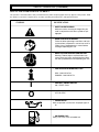
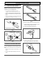
990r
OPERATOR’S
MANUAL
MODEL NO. 990r
IMPORTANT MANUAL
DO NOT THROW AWAY
1
INTRODUCTION
TABLE OF CONTENTS
THANK YOU
I.
California Emission Regulations ................................3
Thank you for purchasing this quality product. This modern
outdoor power tool has been designed to provide you with
many hours of useful service. You will find it to be a great
labor-saving device.
II.
Safety Warnings ......................................................3-6
A. Safety Warnings for Brush Blade ..........................4
B. Safety and International Symbols ......................5-6
III.
Assembly Instructions ..........................................7-10
A. Adjusting the J-Handle ..........................................7
B. Installing the Shoulder Strap ................................7
C. Installing the Brush Blade......................................8
D. Installing the Line Spool ........................................9
E. Operating Split Boom Coupler ............................10
IV.
Oil and Fuel Information......................................11-12
V.
Starting/Stopping Instructions..................................13
VI.
Operating Instructions ..............................................14
A. Adjusting the Trimming Line Length ..................14
B. Decorative Trimming ............................................14
C. Using the Brush Blade ........................................14
This operator's manual provides you with easy-to-understand operating instructions. Read the entire manual and
follow all of the instructions to keep your new power tool in
top operating condition.
The other manual that came with your power tool, the
parts manual, contains all of the information that you need
to order parts.
PRODUCT REFERENCES, ILLUSTRATIONS AND SPECIFICATIONS
All information, illustrations and specifications in this manual are based on the latest product information available at
the time of printing. We reserve the right to make changes
at any time without notice.
SERVICE INFORMATION
Service on this power equipment within and after
the warranty period can be performed by any
Ryobi Authorized Service Dealer.
Dial 1-800-345-8746 in the United States and
1-800-265-6778 in Canada to obtain the listing of
servicing dealers in your area.
DO NOT RETURN UNIT TO RETAILER.
NOTE:
PROOF OF PURCHASE WILL BE
REQUIRED FOR WARRANTY
SERVICE.
VII. Maintenance and Repair Instructions ................15-24
A. Maintenance Schedule ........................................15
B. Line Installation ..............................................16-17
C. Gear Housing Service ..........................................18
D. Air Filter Maintenance ..........................................19
E. Carburetor Adjustment ..................................20-21
F. Inspecting/Cleaning the Muffler ......................21-22
G. Replacing the Spark Plug ....................................23
H. Checking/Adjusting Valve Clearance ............23-24
VIII. Cleaning and Storage ..............................................25
IX.
Specifications ..........................................................25
X.
Troubleshooting Chart ..............................................26
XI.
California Emission Control Warranty Statement ....27
XII. Warranty ..................................................................28
California Proposition 65 Warning:
MAKE SURE THIS MANUAL IS READ AND
CAREFULLY UNDERSTOOD BEFORE STARTING OR OPERATING THIS EQUIPMENT.
THIS PRODUCT IS COVERED BY ONE OR MORE OF THE US PATENTS LISTED BELOW:
5,241,932; 5,176,116; 4,779,405; 4,651,422; 4,589,742; 4,505,040; 4,463,498; 4,356,605; 4,342,235;
4,223,441. OTHER PATENTS PENDING.
NOTE: For users on U. S. Forest Land and in the states of California, Maine, Oregon and Washington. All
U.S. Forest Land and the state of California (Public Resources Codes 4442 and 4443), Oregon and
Washington require, by law that certain internal combustion engines operated on forest brush and/or grasscovered areas be equipped with a spark arrester, maintained in effective working order. Check with your
state or local authorities for regulations pertaining to these requirements. Failure to follow these
requirements could subject you to liability or a fine. This unit is factory-equipped with a spark
arrester. The replacement part number for the spark arrester is 180890.
2
CALIFORNIA EMISSION REGULATIONS
The engine of your lawn and garden care product
meets the 1995 California emissions regulations.
To ensure that your unit continues to meet these
regulations, refer to the following information and
instructions in this operator's manual.
These units are identified by the label on the engine
of your product. A typical identification label is
shown.
SAFETY WARNINGS
THE PURPOSE OF SAFETY SYMBOLS IS TO ATTRACT
YOUR ATTENTION TO POSSIBLE DANGERS. THE
SAFETY SYMBOLS, AND THE EXPLANATIONS WITH
THEM, DESERVE YOUR CAREFUL ATTENTION AND
UNDERSTANDING. THE SAFETY WARNINGS DO NOT
BY THEMSELVES ELIMINATE ANY DANGER. THE
INSTRUCTIONS OR WARNINGS THEY GIVE ARE NOT
SUBSTITUTES FOR PROPER ACCIDENT PREVENTION
MEASURES.
SYMBOL
•
Fuel is extremely flammable and its vapors can
explode if ignited. Always stop the engine and allow it
to cool before filling the fuel tank. Do not smoke while
filling the fuel tank. Keep sparks and open flames
away from the area.
•
Store fuel only in containers designed and approved
for the storage of such materials.
•
Pressure can build up in the fuel tank. Loosen the fuel
tank cap slowly to relieve any pressure in the tank.
•
Add fuel in a clean, well-ventilated area. Wipe up any
spilled fuel immediately. If fuel has been spilled, allow
it to dry completely before starting the engine.
•
Move the trimmer at least 3 m (10 ft) from the fueling
point before starting the engine.
•
Thoroughly inspect the trimmer for loose or damaged
parts before each use. Do not use until adjustments or
repairs are made.
•
Avoid accidental starting. Be in the starting position
whenever pulling the starting rope.
•
Keep all bystanders, especially children, and pets at
least 10 m (33 ft) away from the area.
•
Carefully inspect the areas to be cut. Remove all
debris that could become entangled in the string or
blade. Also remove any objects that could be thrown
during cutting.
•
Before starting, make sure the string head is not in
contact with anything.
•
Check the oil level before each use.
MEANING
WARNING:
Failure to obey a safety
warning can result in injury
to yourself and others.
NOTE:
FUEL AND PRE-OPERATIONAL
Advises you of information
or instructions vital to the
operation or maintenance
of the equipment.
3
SAFETY WARNINGS
OPERATIONAL
•
Wear safety glasses/goggles at all times when
operating this trimmer.
•
Dress properly. Do not operate this trimmer when
barefoot or wearing open sandals. Always wear sturdy,
rubber-soled footwear. The use of gloves, ear/hearing
protection and long pants are recommended.
•
•
Do not wear loose fitting clothing or articles such as
scarves, strings, chains, ties, etc. because they could
get drawn into the air intake. Also make sure long hair
does not get drawn into the air intake.
Keep hands, face, and feet away from all moving parts.
Do not attempt to touch or stop the string when it is
rotating.
•
Do not touch the muffler or cylinder. These parts get
extremely hot from operation and remain hot for a short
time after the equipment is turned off.
•
Always hold the trimmer with both hands when
operating. Keep a firm grip on both the front and rear
handles or grips.
•
Operate this trimmer only in a well-ventilated area -outdoors. Carbon monoxide exhaust fumes can be lethal in
a confined area.
•
If you strike or become entangled with a foreign object,
stop the engine immediately and check for damage.
Repair any damage before further operation is
attempted. Do not operate the trimmer with loose or
damaged parts.
OTHER SAFETY WARNINGS
•
Store the trimmer in an appropriate and dry location to
prevent unauthorized use and damage.
SAFTEY WARNINGS FOR
THE BRUSH BLADE
DURING USE
•
Observe the safety warnings on page 3.
•
Always use the shoulder strap when using the brush
blade accessory.
•
Keep the J-handle between the operator and cutting
head at all times.
•
Do not under any conditions cut with the blade located
over 76.2 cm (30 inches) or more above the ground
level.
•
Scything should be done with extreme care and caution.
•
For operation with the standard 4-tooth blade, do not
cut anything thicker than 13 mm (1/2 inch) or a violent
kickback could occur.
•
Do not attempt to touch or stop the blade when it is
rotating.
•
Do not run the unit at high speed when not cutting.
•
If you strike or become entangled with a foreign object,
stop the engine immediately and check for damage.
Have any damage repaired before further operation is
attempted. Do not operate unit with a bent, cracked or
dull blade.
•
Use the right tool. Do not use this trimmer for any job
except that for which it is intended.
•
Do not force the tool at a rate faster than it is able to
cut effectively.
•
Do not overreach. Keep proper footing and balance at
all times.
•
Keep the unit clean of vegetation and other materials.
They may become lodged between the blade and guard.
•
Always remain alert. To prevent injury to yourself and
others, do not operate this trimmer if you are fatigued.
•
•
Do not operate the engine faster than the speed
necessary to cut, trim or edge. Do not run the engine
at high speed when not cutting.
Stop the engine IMMEDIATELY if you feel excessive
vibration. Vibration is a sign of trouble. Inspect
thoroughly for loose nuts, bolts or damage before
continuing. Repair or replace affected parts as
necessary.
•
Do not extend the trimming line beyond the length
specified in this manual.
•
Always stop the engine when cutting is delayed or when
walking from one cutting location to another.
•
Use only genuine replacement parts when servicing this
trimmer. These parts are available from your authorized
dealer. The use of non-standard parts, or other
accessories or attachments not designed for this
trimmer, could result in serious injury to the user or
damage to the trimmer.
•
Do not operate the unit while under the influence of
drugs, alcohol, or any medication.
4
AFTER USE
•
Clean blades with a household cleaner to remove any
gum buildup. Then oil the blades with machine oil to
prevent rust.
•
Store the unit in an appropriate area to protect the blade
from unauthorized use or damage.
SAFETY WARNINGS (Continued)
SAFETY AND INTERNATIONAL SYMBOLS
This operator's manual describes safety and international symbols and pictographs that may appear on this product. Read
the operator's manual for complete safety, assembly, operating and maintenance and repair information.
SIGNIFICATION
SYMBOL
• SAFETY ALERT SYMBOL.
Indicates caution, warning or danger. May be
used in conjunction with other symbols or pictographs.
• READ OPERATOR'S MANUAL.
Failure to follow operating instructions and safety precautions in operator's manual can result in
serious injury. Read operator's manual before
starting or operating this unit.
• WEAR EYE AND HEARING PROTECTION.
Warning. Thrown objects and loud noise can
cause severe eye injury and hearing loss. Wear
ear and eye protection when operating this unit.
• FOR SERVICE INFORMATION, CALL:
USA: 1-800-345-8746
CANADA: 1-800-265-6778
I
O
• IGNITION / POWER SWITCH.
ON / START / RUN
• IGNITION / POWER SWITCH.
OFF OR STOP
• INDICATES OIL.
Refer to operator's manual for the proper type of
oil.
• UNLEADED FUEL.
Always use clean, fresh unleaded fuel.
5
SAFETY WARNINGS (Continued)
SYMBOL
SIGNIFICATION
• PRIMER BULB.
Push primer bulb, fully and slowly, 5 to 7 times.
•
CHOKE CONTROL.
FULL CHOKE position.
•
CHOKE CONTROL.
PARTIAL CHOKE position.
• CHOKE CONTROL.
RUN position.
•
THROWN OBJECTS AND ROTATING CUTTER
CAN CAUSE SEVERE INJURY. Warning. Do not
operate without guard in place. Keep away from
rotating cutter.
•
BRUSHCUTTERS –
REPLACE DULL BLADE.
Do not sharpen the brush blade. Sharpening the
blade can cause the blade tip to break off while in
use. This can result in severe personal injury.
•
6
BRUSHCUTTER SAFETY.
Warning. Thrown objects and rotating cutter can
cause severe injury. Keep bystanders, especially
children and pets, at least 10 m (30 feet) away
from the cutting area. Plastic string guard must
be used when using the string head.
ASSEMBLY INSTRUCTIONS
ADJUSTING THE J-HANDLE
The J-handle is shipped completely assembled on Model
990r (Fig. 1). Use the following instructions to adjust the
J-handle to the correct operating position.
1. Loosen the four (4) mounting screws on the
J-handle. It is not necessary to remove the screws.
2. Slide the J-handle through the clamp until the arrow /
white line on the decal touches the clamp assembly
(Fig. 2).
3. Position the handle grip as desired (forward and back)
and tighten the mounting screws evenly.
Fig. 3
To install the shoulder strap, use the following instructions.
1. Take the end of the shoulder strap without the buckle
and push it through the ring on the snap.
2. Loop the strap through the buckle (Fig. 4).
Handle Position as Shipped
Fig. 1
Clamp Assembly
Handle
Position
Decal
Fig. 4
Fig. 2
3. Snap the shoulder strap onto the wire connector
(Fig. 5). Adjust the length of the strap as desired.
INSTALLING THE SHOULDER STRAP
Your unit is equipped with a shoulder strap pad. To install
the pad onto the shoulder strap, use the following instructions.
1. Wrap the end of the strap over a blunt object, i.e. ruler
(Fig. 3).
2. Push the strap through the pad (Fig. 3). Remove the
object..
Fig. 5
7
ASSEMBLY INSTRUCTIONS (Continued)
INSTALLING THE BRUSH BLADE
1. Remove the line guard.
2. Insert the locking rod into the locking rod slot. Rotate
the line spool clockwise. Remove the line spool and
retainer washer from the shaft (Fig. 6).
Line Guard
Locking
Rod Slot
4. Install the blade, washer, and lock nut. Insert the
locking rod into the locking rod slot (Fig. 7). Make
sure that the blade stays flat against the washer while
tightening the lock nut counterclockwise until it is
finger-tight.
5. If you have a torque wrench, tighten the lock nut to
225-250 in•lb (25.3-28.1 N•m), while holding the
locking rod in the locking rod slot (Fig. 7).
If you do not have a torque wrench, thread the
lock nut onto the brush blade by hand as tightly as
possible (Fig. 8). Using an open-ended wrench, rotate
the nut 1/2 - 3/4 of a full turn (minimum) (Fig. 9).
The torque of the nut should be within the required
specifications of 225-250 in•lb (25.3-28.1 N•m).
The blade tooth cover can now be removed.
Blade Guard
Locking Rod
Retainer Washer
Bump Head/
Line Spool
Fig. 6
3. Make sure that you have all of the parts necessary to
install the brush blade (Fig. 7). Do not remove the
blade tooth cover off of the blade. Always wear gloves
while handling or installing the blade.
Fig. 8
Locking
Rod Slot
Blade Guard
1/2-3/4 turn
Locking Rod
Fig. 9
Blade
Retainer Washer
Blade Tooth
Cover
Lock Nut
Fig. 7
8
ASSEMBLY INSTRUCTIONS (Continued)
6. When assembling the brush blade, the blade edge
should line up with the blade locating mark on the
casting (Fig. 10). The brush blade should be within a
blade thickness of the mark. If the blade isn't lined up
correctly, refer to Fig. 7 for reassembly.
Blade Locating
Mark
Fig. 10
WARNING
Make sure the blade is flat against the washer
after the lock nut is tightened. If the blade is
off-center, the trimmer will be damaged by
vibration, and the blade may fly off. Failure to
obey this warning may cause injury to yourself
or others.
INSTALLING THE LINE SPOOL
1. Install the blade guard over the brush blade. Insert the
locking rod into the locking rod slot. Loosen the lock
nut by turning it clockwise (Fig. 7).
2. Remove the lock nut, retaining washer and brush
blade.
3. Make sure that you have all of the necessary parts to
install the line spool (Fig. 6).
4. Insert the locking rod tool into the locking rod slot
and place the washer on the shaft (Fig. 6). Screw the
spool counterclockwise onto the shaft.
5. Install the line guard using three (3) screws (Fig. 6).
Tighten the screws securely.
9
ASSEMBLY INSTRUCTIONS (Continued)
OPERATING THE
SPLIT BOOM® COUPLER
Installing the Lower (Attachment) Boom
1. Loosen the wing screws. This will allow the lower
boom to be inserted into the coupler (Fig. 12).
Model 990r is equipped with a Split Boom® coupler,
which enables optional attachments to be installed on this
unit.
2. Remove the protective cover or hanger from the lower
(attachment) boom. Push the lower (attachment)
boom into the coupler (Fig. 13).
The optional attachments are:
3. Before locking the release button into the coupler,
rotate the boom 90 degrees; then rotate the lower
boom back 90 degrees. This will ensure the drive
shafts in both the upper and lower booms are
engaged.
Sweeper/Blower ......................................................SB720r
Vacuum ......................................................................LV720r
Edger ........................................................................LE720r
Cultivator ..................................................................GC720r
Straight Shaft Trimmer..............................................SS720r
Curved Shaft Trimmer ..............................................CS720r
Tree Pruner ................................................................TP720r
Removing the Lower (Attachment) Boom
NOTE:
3. Locate and lock the release button into the hole in
coupler (Fig. 11).
4. Check the sight hole to make sure both ends of the
boom are together (Fig. 13). Tighten the wing screws
before using the unit.
To make removing the boom easier,
place the unit on the ground or on a
table.
Lower Boom
Thumb Screws (2)
1. Loosen the wing screws (Fig. 11).
2. Push the release button (Fig. 11).
3. Pull the lower boom straight out of the coupler (Fig. 12).
Coupler
Thumb Screw
Upper
Boom
Release
Button
Fig. 12
Release Button
Coupler
Thumb Screw
Thumb
Screws (2)
Sight Hole
Fig. 11
Coupler
Fig. 13
10
OIL & FUEL INFORMATION
THIS ENGINE IS CERTIFIED TO OPERATE ON UNLEADED GAS ONLY.
NOTE:
BE SURE TO READ THESE
INSTRUCTIONS CAREFULLY BEFORE
ATTEMPTING TO START OR OPERATE
THIS UNIT. Using old or improper oil or
fuel can cause engine damage. This type
of damage will void the engine warranty.
RECOMMENDED OIL TYPE
Using the proper type and weight of oil in the crankcase is
extremely important. Check the oil before each use and
change the oil regularly. Failure to use the correct oil, or
using dirty oil, can cause premature engine wear and failure.
Use high-quality SAE 30 weight oil of API (American
Petroleum Institute) service class SG, SF.
Fig. 15
ADDING OIL TO CRANKCASE - INITIAL
USE
Your unit is supplied with one bottle of oil, which contains
100 ml (3.4 fluid oz) of SAE 30 SF, SG oil (Fig. 14).
1. Open the bottle of oil.
Fig. 16
2. Install the funnel spout.
4. Reinstall oil fill plug / dipstick into the crankcase.
NOTE:
Funnel Spout
100 ml
(3.4 oz)
Level
Save the bottle and funnel spout for
future use.
NOTE: DO NOT ADD OIL TO THE FUEL.
CHECKING THE OIL
The importance of checking and maintaining the proper oil
level in the crankcase cannot be overemphasized. Check
the oil BEFORE EACH USE as follows:
1. Make sure the engine is stopped, level (Fig. 16) and is
cool so the oil has had time to drain into the
crankcase.
Fig. 14
3. Remove the oil fill plug / dipstick from the crankcase.
Pour the entire bottle of oil into the crankcase (Fig.
15). Make sure the engine is level (Fig. 16) when the oil
is poured into the crankcase.
2. To keep dirt, grass clippings, etc. out of the engine,
clean the area around the oil fill plug / dipstick before
removing it.
3. Remove the oil fill plug / dipstick; wipe the oil off.
Reinsert it into the crankcase. Thread the oil fill plug /
dipstick into the crankcase.
4. Remove the oil fill plug / dipstick and check the oil
level. The oil level should be up to the top of the dipstick (Fig. 17).
5. If the level is low, add the oil to the top of the dipstick
(Fig. 17). Always check the level with the dipstick
before adding more oil.
11
OIL & FUEL INFORMATION (Continued)
RECOMMENDED FUEL TYPE
WARNING
O-ring
Full (100 ml/3.4 oz)
Add Oil
Fig. 17
Fuel is extremely flammable and its vapors can
explode if they are ignited. Always stop the
engine and allow it to cool before filling the fuel
tank. Do not smoke while filling the tank. Keep
sparks and open flames away from the area.
Fill the fuel tank, using clean, fresh, unleaded gasoline.
NOTE:
CHANGING THE OIL
For a new engine, change the oil after the first 10 hours of
operation. Thereafter, change the oil after every 25 hours
or before storing the unit for an extended period of time.
Change the oil while the engine is still warm. The oil will
flow freely and carry away more impurities.
Change the oil as follows:
Alcohol blended fuel absorbs moisture
(water). As little as 1% moisture in the
fuel can cause fuel to separate and form
acids when stored.
If this type of fuel must be used, use
fresh fuel (less than 60 days old).
DEFINITION OF BLENDED FUELS
Today's fuels are often a blend of gasoline and one or
more oxygenates such as ethanol, methanol or MTBE
(ether).
1. Remove the oil fill plug / dipstick.
2. Pour the oil into a container by tipping the trimmer in
a vertical position (Fig. 18). Be sure to allow ample
time for complete drainage. Dispose of oil properly.
USE OF BLENDED FUELS
If you choose to use a blended fuel or its use is unavoidable, the following precautions are recommended.
1. Always use fresh fuel.
2. Use the special additive GASOHOL GAS TREATMENT® (by Gold Eagle) or an equivalent to inhibit
corrosion.
3. Drain tank and run engine dry before storing the
unit.
USE OF FUEL ADDITIVES
Fig. 18
3. Fill the crankcase, with new oil of the proper type, to
the top of the dipstick. Use the bottle saved from the
initial use.
4. Reinstall the oil fill plug / dipstick and tighten securely.
12
NOTE:
Make sure the O-ring is in place on the
oil fill plug when checking and changing
the oil.
NOTE:
To prevent extensive engine wear or
damage, always maintain the proper oil
level in the crankcase. Never operate the
engine with oil level below the bottom of
the dipstick.
The use of fuel additive such as STA-BIL® Gas Stabilizer
or an equivalent, will inhibit corrosion and minimize the formation of gum deposit. Add (23 ml) 0.8 oz per gallon of
fuel per instructions on container. NEVER add fuel additives directly to the unit's fuel tank. Using a fuel additive
can keep fuel fresh for up to six (6) months.
STARTING/STOPPING INSTRUCTIONS
1. CHECK THE OIL LEVEL IN THE
CRANKCASE, AND PUT THE IGNITION
SWITCH IN THE "RUN" (I) POSITION. See
Figure 20 for the location of the ignition switch.
Ignition Switch
STOP
(O)
RUN
(I)
2. FULLY PRESS AND RELEASE THE PRIMER
BULB 5 TO 7 TIMES. See Fig. 21 for the primer
bulb location.
3. PLACE THE CHOKE LEVER IN THE FULL
“CHOKE” POSITION. See Fig. 21.
NOTE: For a warm engine, go directly to
Throttle Trigger
Step 5 (place the choke lever directly
in the "PARTIAL" choke position).
See Fig. 21.
4. WITH THE UNIT ON THE GROUND, PULL
THE STARTER ROPE QUICKLY UNTIL THE
ENGINE SOUNDS LIKE IT WANTS TO RUN
(no more than 5 pulls). See Fig. 22.
Fig. 20
RUN
Position
CHOKE
LEVER
PARTIAL
CHOKE
Position
5. PLACE THE CHOKE LEVER IN THE
“PARTIAL” POSITION (Fig. 21). PULL THE
STARTER ROPE QUICKLY UNTIL THE
ENGINE STARTS (no more than 5 pulls).
See Fig. 22.
FULL
CHOKE
Position
6. If the engine does not start, repeat steps 2 to 5.
PRIMER
BULB
7. RUN THE ENGINE FOR 30 SECONDS, WITH
THE THROTTLE LEVER FULLY SQUEEZED (Fig.
20), TO WARM UP. PLACE THE CHOKE
LEVER IN THE “RUN” POSITION (Fig. 21).
Fig. 21
NOTE: In colder weather, run the engine
for 2 to 3 minutes to warm up.
8. TO STOP THE ENGINE, PUT THE IGNITION
SWITCH IN THE "STOP" (O) POSITION. See
Fig. 20.
Starter
Rope
NOTE: When storing the unit, place the unit
flat on the floor instead of hanging it
by the guard or the cutting head
(Fig. 19).
Throttle
Trigger
Fig. 19
Fig. 22
13
OPERATING INSTRUCTIONS
ADJUSTING THE TRIMMING LINE
LENGTH
Your trimmer is equipped with a bump head that allows
the operator to release more trimming line without stopping the engine. To release additional line, lightly tap the
trimming head on the ground (Fig. 23) while operating the
trimmer at high speed.
USING THE BRUSH BLADE
1. Always maintain the proper stance when using the
brush blade (Fig. 25).
Sharpening the Brush Blade
WARNING
Do not sharpen the brush blade. Sharpening
the blade can cause the blade tip to break off
while in use. This can result in severe
personal injury to yourself or others.
The brush blade is designed with a second set of teeth,
which can be used by removing the blade, turning it
upside down, and reinstalling it.
If a crack is noticed, install a new blade from your
authorized service dealer.
Fig. 23
NOTE:
Always keep the trimming line fully
extended. Line release becomes more
difficult as cutting line becomes shorter.
Each time the head is bumped, about 25.4 mm (1 in) of
trimming line is released. A blade in the line guard will cut
the line to the proper length if excess line is released.
For best results, tap the head on bare ground or hard soil.
If line release is attempted in tall grass, the engine may
stall.
DECORATIVE TRIMMING
Decorative trimming is accomplished by removing all
vegetation around trees, posts, fences, etc. Use a
30-degree angle when trimming with this method (Fig. 24).
Fig. 25
NOTE:
Do not use the brush blade for edging.
Use the LE720r edger attachment.
WARNING
Fig. 24
14
Keep the J-handle between the operator and
cutting head at all times.
MAINTENANCE AND REPAIR INSTRUCTIONS
MAINTENANCE SCHEDULE
These required maintenance procedures should be performed at the frequency stated in the
table. They should also be included as part of any seasonal tune-up.
FREQUENCY
MAINTENANCE REQUIRED
Daily or
Before
Starting
Engine
Fill fuel tank.
Check oil level.
Every
10 Hours
Change oil after initial use.
Clean and re-oil air filter.
Every
25 Hours
Change oil.
Every
50 Hours
Check spark plug condition and gap.
Check rocker arm to valve clearance.
Check spark arrester screen.
REFER TO:
Page 11
Pages 10-11
Page 11
Page 18
Pages 10-11
Page 22
Page 22
Page 21
15
MAINTENANCE AND REPAIR INSTRUCTIONS (Continued)
2. Remove the inner reel (Fig. 27).
LINE INSTALLATION
The trimming line may be replaced by two different methods - rewinding the existing reel or installing a prewound
reel.
REWINDING THE EXISTING REEL
To rewind the existing reel you must:
Inner Reel
1.
2.
3.
4.
Check for the correct line size.
Remove the existing reel and spring.
Wind the existing reel with the new line.
Reinstall the existing reel and spring.
Fig. 27
The Correct Line to Use
3. Use a clean cloth to clean the inner surface of the
outer spool (Fig. 28).
WARNING
NOTE:
Always use genuine Monoflail® replacement line.
Do not use metal-reinforced line.
Always clean the inner reel, outer spool,
and shaft before reassembling the
bump head.
It is very important to use the correct size line. A line with
a diameter of 2.41 mm (.095 in) must be used. The
engine may overheat and fail if you use a larger line.
Removing the Existing Reel
1. Hold the outer spool with one hand and unscrew the
Bump Knob clockwise (Fig. 26). Inspect the captured
bolt inside the Bump Knob to make sure it moves
freely. Replace the Bump Knob if it is damaged.
Fig. 28
4. Check the indexing teeth on the inner reel and outer
spool for wear (Fig. 29). If necessary, deburr or replace
the reel and spool.
Bump Knob
Fig. 26
16
Fig. 29
MAINTENANCE AND REPAIR INSTRUCTIONS (Continued)
Winding the Existing Reel
1. Take approximately 12.7 m (50 ft) of new trimming
line, loop it into two equal lengths. Insert each end of
the line through one of the two holes in the inner reel
(Fig. 30). Pull the line so that the loop is as small as
possible.
Fig. 32
Reinstalling the Reel
Fig. 30
2. Wind the lines, in even and tight layers, onto the reel
(Fig. 31). Wind the line in the direction indicated on
the inner reel. Be sure not to overlap the two ends of
the line.
NOTE:
Placing your index finger between the
two (2) lines while winding the line will
prevent overlapping of the lines.
NOTE:
Failure to wind the line in the direction
indicated will cause the Bump Head to
operate incorrectly.
1. Insert the ends of the line through the eyelets in the
outer spool (Fig. 33). Place the inner reel into the outer
spool. Grasp the ends and pull firmly to release the
line from the holding slots in the spool.
NOTE:
The spring must be in the center of the
outer spool.
Fig. 33
2. Install the bump knob and tighten counterclockwise
(see Fig. 26). Add a small amount of grease or oil to
the threads on the Bump Knob bolt to make it easier
to remove the Bump Knob the next time. Line installation is now complete.
INSTALLING A PREWOUND REEL
Fig. 31
1. Follow the instructions in THE CORRECT LINE TO
USE.
3. Insert the ends of the line into the two holding slots
(Fig. 32).
2. Follow the instructions in REMOVING THE EXISTING
REEL.
3. Follow the instructions in REINSTALLING THE REEL.
17
MAINTENANCE AND REPAIR INSTRUCTIONS (Continued)
GEAR HOUSING SERVICE
WARNING
The gear housing gets very warm after long periods of use. Do not touch the housing until it has
cooled.
1. Check the gear housing for lubricant every 50 hours
of operation.
2. To check the lubricant level, remove the fill plug
(Fig. 34). The lubricant should be up to the bottom
edge of the check hole. If it is low, bring the level up
with a good quality, lithium-based, #2, multi-purpose
grease.
3. Reinstall the fill plug and tighten securely to prevent
leakage.
Fill Plug
Fig. 34
18
MAINTENANCE AND REPAIR INSTRUCTIONS (Continued)
AIR FILTER MAINTENANCE
NOTE:
CLEAN AND RE-OIL THE AIR FILTER
EVERY 10 HOURS OF OPERATION.
Your unit’s air filter is one of the most
important areas to maintain. If it is not
maintained, you will void the warranty.
Before cleaning, make sure the unit is
turned off.
1. Remove the three (3) screws on the carburetor/air
filter cover assembly. Remove the air filter cover
(Fig. 35).
NOTE:
The choke lever should be in the
"PARTIAL" position to remove and
install the air filter cover.
Fig. 37
4. Apply enough clean SAE 30 oil to saturate the filter
(Fig. 38).
Screws
Choke Lever
Screw
Fig. 38
5. Squeeze the filter to spread the oil (Fig. 39).
Fig. 35
2. Remove the air filter (Fig. 36).
Air Filter
Fig. 39
6. Reinstall the filter (see Fig. 36), air filter cover and
screws (see Fig. 35). Torque the screws to 2.8-3.4
N•m (25-30 in•lb).
Fig. 36
3. Wash the filter in detergent and water (Fig. 37). Rinse
the filter thoroughly and allow it to dry.
NOTE:
If the unit is operated without the air
filter cover installed, you will void
the warranty.
19
MAINTENANCE AND REPAIR INSTRUCTIONS (Continued)
CARBURETOR ADJUSTMENT
Throttle
Lever
This unit is equipped with a diaphragm-type carburetor
that has been carefully calibrated at the factory. In most
cases, no further adjustment will be required.
NOTE:
Idle Speed
Screw
To meet the 1995 California emission
regulations, the carburetor has adjustment needle limiter caps to restrict the
amount of adjustment.
The condition of the air filter is important to the operation
of the trimmer. A dirty air filter will restrict the air flow,
which upsets the fuel-air mixture in the carburetor. The
resulting symptoms are often mistaken for an out-ofadjustment carburetor. Therefore, check the condition of
the air filter before adjusting the carburetor. Refer to
Air Filter Maintenance.
High Speed
Mixture Needle
Idle Speed
Mixture Needle
If the following conditions are experienced, it may be necessary to adjust the carburetor:
•
•
•
•
The engine will not idle
The engine hesitates or stalls on acceleration
The loss of engine power that is not corrected by
cleaning the air filter, muffler, spark arrester screen or
adjusting the valve clearance
The engine operates in an erratic or fuel rich condition
The carburetor has three basic adjustments: the idle
speed, idle speed mixture and high speed mixture.
NOTE:
The string guard and line spool must be
installed and the cutting line extended to
its full cutting length when making
carburetor adjustments.
Fig. 40
4. Start the engine and let it run for three (3) to five (5)
minutes with the throttle trigger fully squeezed.
5. Release the throttle trigger and let the engine idle. If
the engine stops, turn the idle speed screw (Fig. 40)
n (clockwise) 1/8 turn at a time (as required) until
the engine idles.
6. Final High Speed Mixture Needle Adjustment:
a.
Adjusting the Carburetor
1. Clean the air filter if it is dirty. Refer to Air Filter
Maintenance in the enclosed operator's manual.
2. Make the initial settings with the engine stopped.
These initial settings should allow you to start and
warm up the trimmer before making the final adjustments.
Initial Idle Speed Setting: Back the idle speed screw
(Fig. 40) out (counterclockwise) until it does not
contact the carburetor throttle lever. Then turn the
screw in (clockwise) until it just begins to move the
throttle lever; then continue turning 2 full turns.
3. Initial High Speed Mixture and Idle Speed Mixture
Settings: Turn both the high speed and idle speed
mixture needles halfway between the allowable
movement of the limiter caps.
20
While squeezing the throttle trigger fully, set the
high speed mixture needle at the optimum setting
(Fig. 41). See “Definition of Optimum Setting” on
page 21.
7. Final Idle Speed Mixture Needle Adjustment: Adjust
the idle speed mixture needle for smoothest engine
idle using the following procedure. Do not squeeze
the throttle trigger when adjusting the idle speed mixture needle.
a.
Set the idle speed mixture needle at the
optimum setting (Fig. 41). See “Definition of
Optimum Setting”.
b.
Turn the idle speed mixture needle out
(counterclockwise) to the rich side of
optimum.
The engine should idle and accelerate smoothly.
MAINTENANCE AND REPAIR INSTRUCTIONS (Continued)
CARBURETOR ADJUSTMENT
(Continued)
8. Final Idle Speed Adjustment: Adjust the idle speed
by turning the idle speed screw in (clockwise) or out
(counterclockwise) until the cutting head does not
rotate. Do not squeeze the throttle trigger when
adjusting the idle speed screw.
Definition of Optimum Setting for Idle Speed
Mixture and High Speed Mixture
Adjustments
Always set the idle speed mixture needle and high speed
mixture needle at the optimum setting. To find the optimum setting, use the following instructions.
INSPECTING/CLEANING THE MUFFLER
The muffler should be removed every 25 hours of operation to inspect for excessive carbon build-up. Excessive
deposits around the exhaust ports or exhaust holes will
cause poor engine performance.
Use the following procedure to remove, inspect, clean and
reinstall the muffler.
Removing Muffler
1. Remove the three (3) muffler mounting bolts from the
cylinder (Fig. 42).
Muffler Mounting
Bolt
1. Turn the adjusting needle out (counterclockwise)
from the preliminary setting until the engine speed
decreases (rich). Note the position of the needle.
2. Turn the adjusting needle in (clockwise). The engine
speed may increase, then it will decrease as the needle is turned in (lean). Note the position of the needle.
Muffler Mounting
Bolt
3. Set the adjusting needle midway between the rich
and lean settings, which is the highest engine speed
(Fig. 41).
Lean
Adjust to
Midpoint
Fig. 42
2. Remove the muffler and muffler gasket. Discard the
old gasket (Fig. 43).
Muffler
Rich
Muffler Gasket
Fig. 41
NOTE:
If the carburetor adjustments do not help
the unit to run properly, contact your
authorized service dealer.
NOTE:
If the limiter caps are removed at any
time, your unit will no longer meet
the1995 California emission regulations
and you will void the warranty.
Fig. 43
21
MAINTENANCE AND REPAIR INSTRUCTIONS (Continued)
Muffler Reassembly
Inspection and Cleaning
Inspect the inlet port of the muffler and outlet port of the
cylinder for excessive carbon build-up. Excessive deposits
around the exhaust ports or exhaust holes will cause poor
engine performance.
If carbon build-up cannot be cleaned, replace the muffler.
Inspect the muffler mounting holes for elongation. Replace
the muffler if the holes are elongated.
1. Install a new muffler gasket and place the muffler
baffle in place (Fig. 45).
2. Install the muffler with the three (3) mounting bolts.
Install the lower bolt first to ease the installation of the
top two (2) bolts (Fig. 46).
NOTE:
The 5 mm nut must be held in the slot
next to the spark plug before installing
the top rear muffler bolt.
NOTE:
Be careful not to crossthread the muffler
mounting bolts.
Checking Spark Arrester Screen
This unit is equipped with a spark arrester screen. Every
50 hours of operation, check the spark arrester screen
for debris and / or deposits.
WARNING
Torque the muffler mounting bolts to 40-45 in•lb
(4.5-5.0 N•m).
Muffler Mounting
Bolt
Make sure the muffler is cool before checking
the spark arrester screen to prevent injury.
Check the spark arrester screen as follows:
1. Remove the screw (Fig. 44).
Muffler Mounting
Bolt
2. Remove the cover (Fig. 44).
3. Push the spark arrester screen out of the cover.
Cover
Spark Arrester
Screen
Fig. 45
Screw
Muffler
Muffler Gasket
Fig. 44
4. Inspect the spark arrester screen.
If the screen is clean, reinstall the screen, cover and
screw. If the screen is plugged, replace it.
5. Torque the screw to 15-20 in•lb (1.7-2.2 N•m).
22
Fig. 46
MAINTENANCE AND REPAIR INSTRUCTIONS (Continued)
REPLACING THE SPARK PLUG
Use a Champion RDZ19H spark plug. Correct air gap is
.025 in (0.635 mm). Remove plug after every 50 hours of
operation and check its condition. Allow the engine to
cool before removing the spark plug.
CHECKING / ADJUSTING VALVE TO
ROCKER ARM CLEARANCE
Every 50 hours of operation, remove the rocker arm
cover and check the valve to rocker arm clearance, using
a flat feeler gauge.
1. Stop the engine and pull the wire off of the spark
plug.
NOTE:
2. Clean around the spark plug and remove it from the
cylinder head.
The engine must be cold when checking
or adjusting the clearance.
Check / adjust the clearance as follows:
NOTE:
Replace a cracked, fouled or dirty spark
plug. Do not sand blast, scrape or clean
electrodes because the engine could be
damaged by grit entering the cylinder.
1. Remove the four (4) screws from the engine cover
(Figs. 48 and 49).
2. Remove the engine cover.
3. Set the air gap at .025 in (0.635 mm) using a wire
feeler gauge (Fig. 47). Install a correctly gapped spark
plug into the cylinder head. Torque to 100-110 in•lb
(11.3-12.3 N•m).
Screw
Fig. 48
.025 in
(0.635 mm)
Screws
Fig. 47
Fig. 49
23
MAINTENANCE AND REPAIR INSTRUCTIONS (Continued)
3. Remove the rocker arm cover and gasket, using a T25 Torx® screwdriver (Fig. 50).
The recommended valve to rocker arm clearance for both
the intake and exhaust is 003-.006 in. (.076 mm-.152
mm).
6. If the clearance is not within specification, adjust as
follows:
a.
Turn the adjusting nut (Fig. 52), using an 5/16 in
(8 mm) wrench or nut driver.
To increase the rocker arm to valve clearance,
turn the adjusting nut counterclockwise.
To decrease the rocker arm to valve clearance,
turn the adjusting nut clockwise.
b.
Fig. 50
4. Position the crankshaft so the piston is at the top of
the compression stroke (the rocker arms are free and
loose).
5. Measure the clearance between the valve stems and
rocker arms, using a flat feeler gauge (Fig. 51).
Rocker Arm
Recheck the clearance with a flat feeler gauge
and readjust as necessary (Fig. 49).
7. Reinstall the rocker arm cover using a new gasket.
Torque the rocker arm cover screw to 20-30 in•lb
(2.2-3.4 N•m) (Fig. 50).
Adjusting Nuts
Valve
Fig. 52
Flat Feeler Gauge
8. Reinstall the engine cover and screws (see Figs. 48
and 49 on page 22).
Fig. 51
Torque the top screws to 10-12 in•lb (1.1-1.3 N•m).
Torque the front screw to 10-15 in•lb (1.1-1.7 N•m).
Torque the rear screw with washer to 25-30 in•lb
(2.8-3.4 N•m).
24
CLEANING AND STORAGE
3. Drain the oil from the crankcase and add fresh oil. Pull
the starter rope a few times to lubricate the engine.
WARNING
Always turn off your trimmer before you clean
or perform any maintenance on it.
4. Thoroughly clean the unit and inspect for any loose or
damaged parts. Repair or replace damaged parts and
tighten loose screws, nuts or bolts.
Cleaning
The unit is now ready for storage.
Use a small brush to clean off the outside of the trimmer.
Do not use strong detergents on plastic housing or handle.
They can be damaged by household cleaners that contain
aromatic oils such as pine and lemon, and by solvents
such as kerosene. Wipe off any moisture with a soft cloth.
5. Store the trimmer in a dry, well-ventilated area, and
hang with the cutting head up or place the unit flat on
the floor (Fig. 53).
Storage
If the trimmer will be stored for an extended period of
time, use the following storage procedure.
1. Drain all fuel from the fuel tank. Do not use fuel that
has been stored for more than 60 days.
Fig. 53
2. Start the engine and allow it to run until it stalls. This
ensures that all fuel has been drained from the carburetor.
SPECIFICATIONS
ENGINE
Engine Type ..............................Air-Cooled, 4-Cycle
Displacement ............................26.2 cc
Bore ..........................................32 mm (1.30 in)
Stroke ......................................32.6 mm (1.3 in)
Clutch Type ..............................Centrifugal
Operating RPM ........................7500 rpm
Ignition Type ............................Electronic
Ignition Switch ..........................Slide Switch
Spark Plug ................................Champion RDZ19H
Spark Plug Gap ........................0.635 mm (.025 in)
Fuel Tank Capacity ..................450 ml (16 fl oz)
Oil Capacity ..............................100 ml (3.4 fl oz)
DRIVE SHAFT & CUTTING HEAD
Drive Shaft ................................Steel, 1/4"
Drive Shaft Housing..................Steel Tube, Split Boom®
Operating Weight......................7.78 kg (17.2 lbs)
Throttle Control ........................Finger-Tip Trigger
Shoulder Strap with Pad ..........Standard
Line Spool Diameter ................102 mm (4 in)
Trimming Line Diameter............2.41 mm (.095 in)
Cutting Path Diameter ..............440 mm (18 in)
COLD TORQUE SPECIFICATIONS
Spark Plug ................................11.3-12.3 N•m (100-110
in•lb)
Rocker Arm Cover Screw ........2.2-3.4 N•m (20-30 in•lb)
Brush Blade Lock Nut ..............25.3-28.1 N•m (225-250
in•lb)
Engine Cover Screws (Top) ......1.1-1.3 N•m (10-12 in•lb)
Engine Cover Screw (Front)......1.1-1.7 N•m (10-15 in•lb)
Engine Cover Screw (Rear) ......2.8-3.4 N•m (25-30 in•lb)
Air Filter Cover Screws ............2.8-3.4 N•m (25-30 in•lb)
Spark Arrester
Screen Screw ..........................1.7-2.2 N•m (15-20 in•lb)
25
TROUBLESHOOTING
PROBLEM
Engine Is Difficult to
Start or Will Not Start
CAUSE
ACTION
Ignition switch is “STOP (O)"
Turn switch to “RUN (I)”
Primer bulb wasn’t pushed enough
Press primer bulb fully and slowly 5-7 times
Engine is not choked
Use starting procedure, USING
"FULL" CHOKE" (Page 9)
Empty fuel tank
Fill fuel tank
Engine flooded
Use starting procedure, USING
"PARTIAL" CHOKE (Page 9)
Valve clearance is out of
adjustment
Use adjust valve to rocker arm
clearance procedure (Pages 18 and 19)
Plugged spark arrester screen
Clean or replace spark arrester screen (Page 19)
Spark plug fouled
Clean spark plug and regap or replace
Air filter is plugged
Clean and re-oil air filter or replace (Page 15)
Carburetor misadjusted
Adjust carburetor (Pages 16-17)
Engine Will Not Accelerate
Carburetor misadjusted
Adjust carburetor (Pages 16-17)
Engine Lacks Power or Stalls
When Cutting
Dirty air filter
Clean and re-oil air filter or replace (Page 15)
Valve clearance is out of
adjustment
Use adjust valve to rocker arm
clearance procedure (Pages 18-19)
Dirty spark arrestor screen
Clean or replace screen
Carburetor misadjusted
Adjust carburetor (Pages 16-17)
Not enough fuel in fuel tank
Fill fuel tank
Cutting head out of line
Refill with new cutting line (Pages 13-14)
Inner reel bound up
Replace inner reel (Pages 13-14)
Cutting head dirty
Clean inner reel and outer spool (Pages 13-14)
Indexing teeth worn or burred
Replace inner reel and outer spool
(Pages 13-14)
Line welded
Disassemble cutting head, remove the welded
section and rewind the line
Line twisted when refilled
Disassemble cutting head and rewind reel
Not enough line is exposed
Push the Bump Knob and pull out the line until
a minimum of 102 mm (4 in) is outside of the
cutting head
Oil accumulated in combustion
chamber
Remove the spark plug
Unit operated with low or no oil
Drain the oil from the spark plug hole
Engine Will Not Idle
Cutting Head Will Not Advance
Line
Starter Rope Is Difficult to Pull
or Engine Locks
Pull the starter rope several times to remove
any excess oil from the cylinder
Clean the spark plug and wipe off excess oil
with a dry cloth
Reinstall the spark plug
Check oil before starting
If further assistance is required, contact your local authorized service dealer or call 1-800-345-8746.
26
CALIFORNIA EMISSION CONTROL WARRANTY STATEMENT
YOUR WARRANTY RIGHTS AND OBLIGATIONS
The California Air Resources Board and Ryobi Outdoor Products (ROP), are pleased to
explain the emission control system warranty on your 1995 and later lawn and garden
equipment engine. In California, new lawn and garden equipment engines must be
designed, built and equipped to meet the State's stringent anti-smog standards. ROP
must warrant the emission control system on your lawn and garden equipment engine for
the periods of time listed below provided there has been no abuse, neglect or improper
maintenance of your lawn and garden equipment engine.
MANUFACTURER'S WARRANTY COVERAGE:
•
The warranty period begins on the date the engine or equipment is delivered to the
retail purchaser.
•
The manufacturer warrants to the initial owner and each subsequent purchaser, that the
engine is free from defects in material and workmanship which cause the failure of a
warranted part for a period of two years.
Your emission control system may include parts such as the carburetor or fuel injection
system, the ignition system, and catalytic converter. Also included may be hoses, belts,
connectors and other emission-related assemblies.
•
Repair or replacement of warranted part will be performed at no charge to the owner at
an Authorized Ryobi Service Center. For the nearest location, please contact Ryobi at:
1-800-345-8746.
Where a warrantable condition exists, ROP will repair your lawn and garden equipment
engine at no cost to you including diagnosis, parts and labor.
•
Any warranted part which is not scheduled for replacement, as required maintenance
which is scheduled only for regular inspection to the effect of "Repair or replace as necessary" is warranted for the warranty period. Any warranted part which is scheduled for
replacement as required maintenance will be warranted for the period of time up to the
first scheduled replacement point for that part.
•
The owner will not be charged for diagnostic labor which leads to the determination that
a warranted part is defective, if the diagnostic work is performed at an Authorized Ryobi
Service Center.
•
The manufacturer is liable for damages to other engine components caused by the failure of a warranted part still under warranty.
The 1995 and later utility and lawn and garden equipment engines are warranted for two
years. If any emission-related part on your engine is defective, the part will be repaired or
replaced by ROP.
OWNER'S WARRANTY RESPONSIBILITIES:
•
•
•
As the lawn and garden equipment engine owner, you are responsible for the performance of the required maintenance listed in your operator's manual. ROP recommends
that you retain all receipts covering maintenance on your lawn and garden equipment
engine, but ROP cannot deny warranty solely for the lack of receipts or for your failure
to ensure the performance of all scheduled maintenance.
•
As the lawn and garden equipment engine owner, you should however be aware that
ROP may deny you warranty coverage if your lawn and garden equipment engine
or a part has failed due to abuse, neglect, improper maintenance or unapproved
modifications.
Failures caused by abuse, neglect or improper maintenance are not covered
under warranty.
•
The use of add-on or modified parts can be grounds for disallowing a warranty claim.
The manufacturer is not liable to cover failures or warranted parts caused by the use of
add-on or modified parts.
You are responsible for presenting your lawn and garden equipment engine to an Ryobi
Authorized Service Center as soon as a problem exists. The warranty repairs should be
completed in a reasonable amount of time, not to exceed 30 days.
•
In order to file a claim, go to your nearest Authorized Ryobi Service Center. Warranty
services or repairs will be provided at all Authorized Ryobi Service Centers.
•
Any manufacturer approved replacement part may be used in the performance of any
warranty maintenance or repair of emission related parts and will be provided without
charge to the owner. Any replacement part that is equivalent in performance or durability may be used in non-warranty maintenance or repair and will not reduce the warranty
obligations of the manufacturer.
•
The following components are included in the emission related warranty of the engine,
air filter, carburetor, primer, fuel lines, fuel pick up/fuel filter, ignition module, spark plug
and muffler.
If you have any questions regarding your warranty rights and responsibilities, you should
call 1-800-345-8746.
27
Limited Two-Year Warranty
RYOBI AMERICA CORP. warrants each new RYOBI Product for two (2) years according to the following terms.
This warranty extends to the original retail purchaser only and commences on the
date of original retail purchase.
Any part of the RYOBI Product manufactured or supplied by RYOBI and found in the
reasonable judgement of RYOBI to be defective in material or workmanship will be
repaired or replaced by an authorized RYOBI service dealer without charge for parts
and labor.
The RYOBI Product including any defective part must be returned to an authorized
service dealer within the warranty period. The expense of delivering the RYOBI
Product to the dealer for warranty work and the expense of returning it back to the
owner after repair or replacement will be paid for by the owner. RYOBI’s responsibility in respect to claims is limited to making the required repairs or replacements and
no claim of breach of warranty shall be cause for cancellation or rescission of the
contract of sale of any RYOBI Product. Proof of purchase will be required by the
dealer to substantiate any warranty claim. All warranty work must be performed by
an authorized RYOBI service dealer.
This warranty is limited to ninety (90) days from the date of original retail purchase
for any RYOBI Product that is used for rental or commercial purposes, or any other
income-producing purpose.
This warranty does not cover any RYOBI Product that has been subject to misuse,
neglect, negligence, or accident, or that has been operated in any way contrary to
the operating instructions as specified in the RYOBI Operator’s Manual. This warranty does not apply to any damage to the RYOBI Product that is the result of
improper maintenance or to any RYOBI Product that has been altered or modified so
as to adversely affect the products operation, performance or durability or that has
been altered or modified so as to change its intended use. The warranty does not
extend to repairs made necessary by normal wear or by the use of parts or accessories which are either incompatible with the RYOBI Product or adversely affect its
operation, performance or durability.
In addition, this warranty does not cover:
A. Tune-ups - Spark Plugs, Carburetor Adjustments, Filters
B. Wear items - Bump Knobs, Outer Spools, Cutting Line, Inner Reels, Starter Pulley,
Starter Ropes
RYOBI reserves the right to change or improve the design of any RYOBI Product
without assuming any obligation to modify any product previously manufactured.
ALL IMPLIED WARRANTIES ARE LIMITED IN DURATION TO THE TWO (2) YEAR
WARRANTY PERIOD OR NINETY (90) DAYS FOR PRODUCTS USED FOR ANY
COMMERCIAL PURPOSE. ACCORDINGLY, ANY SUCH IMPLIED WARRANTIES INCLUDING MERCHANTABILITY, FITNESS FOR A PARTICULAR PURPOSE, OR OTHERWISE, ARE DISCLAIMED IN THEIR ENTIRETY AFTER THE EXPIRATION OF THE
APPROPRIATE TWO-YEAR OR NINETY DAY WARRANTY PERIOD. RYOBI’S OBLIGATION UNDER THIS WARRANTY, IS STRICTLY AND EXCLUSIVELY LIMITED TO
THE REPAIR OR REPLACEMENT OF DEFECTIVE PARTS, AND ROP DOES NOT
ASSUME OR AUTHORIZE ANYONE TO ASSUME FOR THEM ANY OTHER OBLIGATION. SOME STATES DO NOT ALLOW LIMITATIONS ON HOW LONG AN IMPLIED
WARRANTY LASTS, SO THE ABOVE LIMITATION MAY NOT APPLY TO YOU.
RYOBI ASSUMES NO RESPONSIBILITY FOR INCIDENTAL, CONSEQUENTIAL OR
OTHER DAMAGES INCLUDING, BUT NOT LIMITED TO EXPENSE OF RETURNING
THE RYOBI PRODUCT TO AN AUTHORIZED SERVICE DEALER AND EXPENSE OF
DELIVERING IT BACK TO THE OWNER, MECHANIC’S TRAVEL TIME, TELEPHONE
OR TELEGRAM CHARGES, RENTAL OF A LIKE PRODUCT DURING THE TIME
WARRANTY SERVICE IS BEING PERFORMED, TRAVEL, LOSS OR DAMAGE TO
PERSONAL PROPERTY, LOSS OF REVENUE, LOSS OF USE OF THE PRODUCT,
LOSS OF TIME, OR INCONVENIENCE. SOME STATES DO NOT ALLOW THE
EXCLUSION OR LIMITATION OF INCIDENTAL OR CONSEQUENTIAL DAMAGES,
SO THE ABOVE LIMITATION OR EXCLUSION MAY NOT APPLY TO YOU.
This warranty gives you specific legal rights, and you may also have other rights
which vary from state to state.
This warranty applies to all RYOBI Products manufactured by RYOBI and sold in the
United States and Canada.
To locate your nearest service dealer dial 1-800-345-8746 in the United States or
1-800-265-6778 in Canada.
RYOBI AMERICA CORP.
5201 Pearman Dairy Rd
Anderson, SC 29622-1207 U.S.A.
RYOBI CANADA INC.
275 Industrial Rd
Cambridge, Ontario NIR 6K2 CANADA
28