1
DVP-MC Bus-Type
Multi-Axis Motion Controller
Operating Manual
DVP-0191420-03
2012-08-17
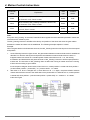
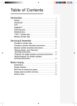
Content
1. OVERVIEW OF DVP10MC11T ..................................................................................................................1-1
1.1. Function..............................................................................................................................................1-1
1.2. Profile and Outline..............................................................................................................................1-2
1.2.1.
Dimension .................................................................................................................................1-2
1.2.2.
Components ..............................................................................................................................1-2
2. INTRODUCTION TO SYSTEM FUNCTION...............................................................................................2-1
2.1. System Architecture ...........................................................................................................................2-1
2.1.1.
COM Port ..................................................................................................................................2-2
2.1.2.
System Construction Structure..................................................................................................2-4
2.1.3.
System Extension......................................................................................................................2-6
2.2. The internal devices ...........................................................................................................................2-8
2.2.1.
The internal devices of PLC module .........................................................................................2-8
2.2.2.
The internal devices of MC motion control module...................................................................2-8
2.3. System Work Principle .....................................................................................................................2-14
2.3.1.
Axis Parameter Setting ...........................................................................................................2-14
2.3.2.
Motion Program Execution Principle .......................................................................................2-19
2.3.3.
CNC Function..........................................................................................................................2-21
2.3.3.1. CNC Program Downloading and Debugging.....................................................................2-22
2.3.3.2. The Protocol for Dynamic Download of CNC Program .....................................................2-22
2.3.3.3. Message Format................................................................................................................2-23
2.3.4.
CAM Function..........................................................................................................................2-24
3. SYSTEM INSTALLATION ..........................................................................................................................3-1
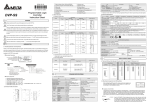
3.1. Electrical Feature ...............................................................................................................................3-1
3.2. System Connection ............................................................................................................................3-3
3.2.1.
Power and IO Wiring .................................................................................................................3-3
3.2.2.
Connected to ASDA-A2 Series of Servo...................................................................................3-6
3.2.3.
Connecting the Extension Module to the Left Side of DVP10MC11T as DeviceNet Master ....3-7
3.2.4.
Connecting the Extension Module (DVP16SP11T) to the Right Side of DVP10MC11T...........3-8
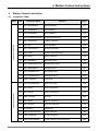
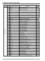
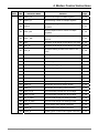
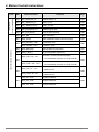
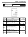
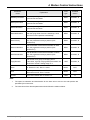
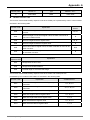
4. MOTION CONTROL INSTRUCTION.........................................................................................................4-1
4.1. Instruction Table .................................................................................................................................4-1
4.2. Axis Status..........................................................................................................................................4-5
4.3. Instruction Usage ...............................................................................................................................4-6
4.4. Single-Axis Instruction Usage ............................................................................................................4-8
4.4.1.
MC_MoveAbsolute....................................................................................................................4-8
4.4.2.
MC_MoveRelative ...................................................................................................................4-14
4.4.3.
MC_MoveAdditive ...................................................................................................................4-18
4.4.4.
MC_MoveSuperImposed ........................................................................................................4-22
4.4.5.
MC_MoveVelocity ...................................................................................................................4-27
4.4.6.
MC_Stop..................................................................................................................................4-30
4.4.7.
MC_PassiveHome ..................................................................................................................4-33
4.4.8.
MC_Power...............................................................................................................................4-36
4.4.9.
MC_Reset ...............................................................................................................................4-37
4.4.10. MC_ReadStatus ......................................................................................................................4-39
4.4.11. MC_ReadActualPosition .........................................................................................................4-40
4.4.12. MC_ReadAxisError .................................................................................................................4-41
4.4.13. DMC_ReadParameter.............................................................................................................4-42
4.4.14. DMC_WriteParameter.............................................................................................................4-43
4.4.15. DMC_SetTorque......................................................................................................................4-44
4.5. Multi-Axis Instruction ........................................................................................................................4-46
4.5.1.
MC_CamTableSelect ..............................................................................................................4-46
4.5.2.
MC_CamIn ..............................................................................................................................4-47
4.5.3.
MC_CamOut ...........................................................................................................................4-66
4.5.4.
DMC_CamSet .........................................................................................................................4-69
4.5.5.
MC_GearIn..............................................................................................................................4-73
4.5.6.
MC_GearOut...........................................................................................................................4-75
4.5.7.
MC_Phasing............................................................................................................................4-77
4.5.8.
DMC_CapturePosition ............................................................................................................4-80
4.5.9.
DMC_VirtualAxis .....................................................................................................................4-86
4.5.10. DMC_ExternalMaster..............................................................................................................4-88
4.6. Logical Instruction ............................................................................................................................4-90
4.6.1.
ADD.........................................................................................................................................4-90
4.6.2.
ADD_DI ...................................................................................................................................4-90
4.6.3.
ADD_R ....................................................................................................................................4-91
4.6.4.
SUB .........................................................................................................................................4-91
4.6.5.
SUB_DI ...................................................................................................................................4-92
4.6.6.
SUB_R ....................................................................................................................................4-92
4.6.7.
MUL.........................................................................................................................................4-93
4.6.8.
MUL_DI ...................................................................................................................................4-93
4.6.9.
MUL_R ....................................................................................................................................4-94
4.6.10. DIV ..........................................................................................................................................4-94
4.6.11. DIV_DI.....................................................................................................................................4-95
4.6.12. DIV_R......................................................................................................................................4-95
4.6.13. AND.........................................................................................................................................4-96
4.6.14. OR ...........................................................................................................................................4-96
4.6.15. XOR.........................................................................................................................................4-97
4.6.16. NOT.........................................................................................................................................4-97
4.6.17. CTU .........................................................................................................................................4-98
4.6.18. CTD .......................................................................................................................................4-100
4.6.19. CTUD ....................................................................................................................................4-102
4.6.20. TON_s ...................................................................................................................................4-104
4.6.21. TOF_s ...................................................................................................................................4-106
4.6.22. TONR_s ................................................................................................................................4-108
4.6.23. TON_ms ................................................................................................................................ 4-110
4.6.24. TOF_ms ................................................................................................................................ 4-111
4.6.25. TONR_ms ............................................................................................................................. 4-112
4.6.26. CMP ...................................................................................................................................... 4-113
4.6.27. CMP_DI................................................................................................................................. 4-114
4.6.28. CMP_R.................................................................................................................................. 4-115
4.6.29. MOV ...................................................................................................................................... 4-116
4.6.30. MOV_DI................................................................................................................................. 4-117
4.6.31. MOV_R.................................................................................................................................. 4-117
4.6.32. MOVF .................................................................................................................................... 4-118
4.6.33. MOVF_DI .............................................................................................................................. 4-119
4.6.34. MOVF_R ...............................................................................................................................4-120
4.6.35. MOVB....................................................................................................................................4-121
4.6.36. MOV_BW ..............................................................................................................................4-122
4.6.37. MOV_WB ..............................................................................................................................4-123
4.6.38. ZCP .......................................................................................................................................4-124
4.6.39. ZCP_DI..................................................................................................................................4-125
4.6.40. ZCP_R...................................................................................................................................4-126
4.6.41. SET .......................................................................................................................................4-127
4.6.42. RESET ..................................................................................................................................4-127
4.6.43. OUT.......................................................................................................................................4-128
4.6.44. R_Trig....................................................................................................................................4-128
4.6.45. F_Trig ....................................................................................................................................4-130
4.6.46. ZRSTM ..................................................................................................................................4-131
4.6.47. ZRSTD ..................................................................................................................................4-132
4.6.48. SQRT_R................................................................................................................................4-133
4.6.49. MOD ......................................................................................................................................4-133
4.6.50. MOD_DI ................................................................................................................................4-134
4.6.51. MOD_R .................................................................................................................................4-134
4.6.52. Real_To_Int ...........................................................................................................................4-135
4.6.53. Real_To_DInt.........................................................................................................................4-135
4.6.54. Int_To_Real ...........................................................................................................................4-136
4.6.55. DInt_To_Real ........................................................................................................................4-136
4.6.56. Offset.....................................................................................................................................4-137
4.6.57. Offset _DI ..............................................................................................................................4-139
4.6.58. Offset _R ...............................................................................................................................4-141
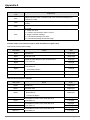
4.7. Application Instruction ....................................................................................................................4-142
4.7.1.
Rotary Cut Technology ..........................................................................................................4-142
4.7.2.
Rotary Cut Parameters .........................................................................................................4-143
4.7.3.
Control feature of rotary cut function.....................................................................................4-143
4.7.4.
Introduction to the Cam with Rotary Cut Function ..............................................................4-144
4.7.5.
Rotary Cut Instructions..........................................................................................................4-148
4.7.5.1. APF_RotaryCut_Init.........................................................................................................4-148
4.7.5.2. APF_RotaryCut_In...........................................................................................................4-150
4.7.5.3. APF_RotaryCut_Out........................................................................................................4-151
4.7.6.
Application Example of Rotary Cut Instructions....................................................................4-152
4.7.7.
Flying Shear Technology .....................................................................................................4-154
4.7.8.
The technological parameters of flying shear function .........................................................4-155
4.7.9.
Control feature of flying shear function .................................................................................4-156
4.7.10. Flying Shear Instructions.......................................................................................................4-158
4.7.10.1. APF_FlyingShear_Init......................................................................................................4-158
4.7.10.2. APF_FlyingShear.............................................................................................................4-160
4.7.11. Sequence Chart on Flying Shear Function ...........................................................................4-162
4.7.12. Application Example of Flying Shear Instructions.................................................................4-163
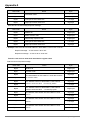
4.8 Explanation of G Codes and Coordinate Motion Instruction..........................................................4-165
4.8.1
G Code Input Format ............................................................................................................4-165
4.8.2
Explanation of G Code Format..............................................................................................4-166
4.8.3
Introduction to G Code Function ...........................................................................................4-168
4.8.3.1
G90: Absolute Mode ........................................................................................................4-168
4.8.3.2
G91: Relative Mode .........................................................................................................4-169
4.8.3.3
G0: Rapid Positioning ......................................................................................................4-170
4.8.3.4
G1: Linear Interpolation ...................................................................................................4-173
4.8.3.5
G2: Clockwise Circular/ Helical Interpolation...................................................................4-177
4.8.3.6
G3: Anticlockwise circular /helical interpolation ...............................................................4-184
4.8.3.7
G17, G18, G19: to specify the circular interpolation plane..............................................4-190
4.8.3.8
G4: Dwell Instruction........................................................................................................4-190
4.8.3.9
G36: Set/Reset Instruction...............................................................................................4-191
4.8.3.10 G37: Status Judgment Instruction ...................................................................................4-191
4.8.4
4.8.4 DMC_NC......................................................................................................................4-192
4.8.5
4.8.5 Coordinate Motion Instructions ....................................................................................4-197
4.8.5.1
DNC_Group (Build Coordinate Motion Instruction Group).........................................4-197
4.8.5.2
Absolute/ Relative Mode Switching Instruction................................................................4-200
4.8.5.3
DNC_MOV(G0)(Rapid positioning instruction) ...........................................................4-201
4.8.5.4
DNC_LIN(G1)(Linear Interpolation Instruction) ..........................................................4-202
4.8.5.5
Circular/ Helical Interpolation(The Coordinates of Center of a Circle Are Set)...........4-204
4.8.5.6
Circular/ Helical Interpolation(Radius Is Set) ..............................................................4-206
4.8.5.7
Plane Selection Instruction ..............................................................................................4-208
4.8.5.8
Program Example ............................................................................................................4-209
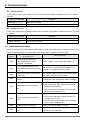
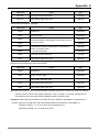
5. TROUBLESHOOTING ...............................................................................................................................5-1
5.1. LED Indicator Explanation..................................................................................................................5-1
5.2. Status Word Instruction ......................................................................................................................5-4
5.3. Error ID in Motion Instructions............................................................................................................5-5
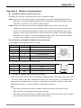
APPENDIX A MODBUS COMMUNICATION ............................................................................................. A-1
APPENDIX B ETHERNET COMMUNICATION.......................................................................................... B-1
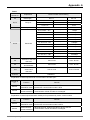
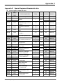
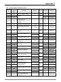
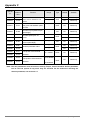
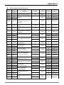
APPENDIX C SPECIAL REGISTERS RELATED WITH AXIS .................................................................. C-1
APPENDIX D EXPLANATION OF HOMING METHODS........................................................................... D-1
APPENDIX E PLC MODULE DEVICES..................................................................................................... E-1
Overview of DVP10MC11T
1. Overview of DVP10MC11T
DVP10MC11T is a type of multi-axis motion controller researched and produced by Delta autonomously on
basis of CANopen field bus. It complies with CANopen DS301 basic communication protocol and DSP402
motion control protocol. Also, it supports motion control standard instruction libraries defined by most
international organizations. It brings great convenience to user to learn to develop projects quickly.
The multi-function controller consists of standard PLC module and MC motion control module. PLC module
is similar to DVP serial PLC in function and usage. User could utilize WPLSoft or ISPSoft programming
software to write and edit the ladder diagram, SFC, instruction table and Delta standard PLC logic programs.
Moreover, PLC supports the two extension ports in its left and right sides. The one in its left side is a parallel
extension port which could be connected with max 7 field bus master modules such as DeviceNet/CANopen
master, Ethernet modules and high-speed analog quantity modules. The other one in its right side is to
connect DVP-S series of PLC extension modules such as low-speed analog quantity and digital quantity
modules.
DVP10MC11T is mainly applied to control the servo drive precisely via CANopen bus so as to accomplish
the functions like the speed control, position control and etc. that user expects.
CANopen Builder software is used to edit the motion control program for DVP10MC11T to achieve all kinds
of complicate motion control tasks.
Its graphical motion control language provided to user to program on the motion control function is easy and
convenient for user to learn and understand.
Besides, CANopen Builder provides the interfaces of G codes editing, preview and electronic cam editing for
user to plan a more distinctive motion control demand.
With communication system adopting the highly reliable CAN bus as main line, DVP10MC11T just need
provide the simple wiring to user.
Thanks to the high-speed and reliable motion control system, DVP10MC11T can be widely applied in the
automation control industry such as packaging, printing, encapsulating, cutting, digital control machine,
automatic storage and so on.
1.1. Function
The PLC module of DVP10MC11T resembles DVP-SX2 MPU. For the detailed function parameter
information, please refer to Application Manual of DVP-ES2/EX2/SS2/SA2/SX2 (Programming). We focus
on the main functions of DVP10MC11T below:
¾ Capable of controlling up to 16 real axes via (CANopen) high-speed bus ( Axis No. range: 1~16)
¾ Virtual axes as well as the external encoder virtual master axis can be constructed in DVP10MC11T.
(Axis No range: 1~18; the numbers of real and virtual axes must be different.)
¾ Equipped with the high-speed floating point processor for handling all kinds of complicate motion control
tasks.
¾ Supporting powerful field bus network by serving as DeviceNet master/slave, CANopen master/slave and
Profibus-DP slave and also making up of the control system with complicate functions.
¾ It has many kinds of IO extensions (high-speed AIAO on the left, low-speed AIAO and DIDO on the right,
temperature module and etc.)
¾ Using the software interface which is easy to operate with complete functions.
¾ Providing the accessory products such as standard bus cables, terminal resistor and terminal
block to wire the circuit easily just by plugging. So users do not need to prepare for them additionally by
themselves.
DVP-MC operating manual
1-1
Overview of DVP10MC11T
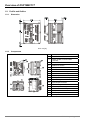
1.2. Profile and Outline
1.2.1.
Dimension
Unit: mm [in.]
1.2.2.
Components
1
2
3
4
5
6
7
8
9
10
11
12
13
14
15
16
17
18
19
1-2
Model name
POWER /RUN /ERR indicator
COM1 /COM2 communication
indicator
CAN, MTL indicator
RUN/STOP switch
Encoder interface
RESET button
COM1 communication port
Ethernet communication port
DIN rail clip
CANopen communication port
Clip for fixing extension module
Input/Output terminals
Clip for fixing extension module
Extension port on the right side
COM2 communication port
24V power interface
Extension port on the left side
Nameplate
DVP-MC operating manual
2. System Function
2. Introduction to System Function
DVP10MC11T is a high-performance controller in charge of 1~ 16 real axes and max. 18 virtual axes with the
application functions like gear box, cam, rotary cut, flying shear. With a standard PLC module inside it,
DVP10MC11T supports the functions of PLC and can be extended with the DeviceNet module, CANopen
module, Ethernet module, high-speed analog-quantity module on its left side and all Slim series of modules
with analog quantity and digital quantity on its right side. In addition, DVP10MC11T provides the standard
RS232, RS485 communication port, CANopen bus interface, Ethernet interface, encoder interface so that
user could handily construct a motion control network with powerful functions.
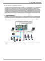
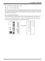
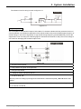
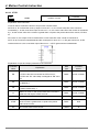
2.1. System Architecture
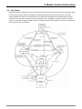
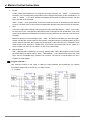
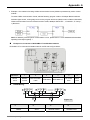
DVP10MC11T can be applied to the construction of a multi-layer industrial network. In the following figure,
the top layer is the network constituted by Ethernet, the middle layer is the network made up of CAN bus
supporting DeviceNet and CANopen protocol, the bottom layer is the network consisting of 485 bus
supporting Modbus.
DVPEN01-SL
DVPCOPM-SL
DVPDNET-SL
DVP10MC11T
Extend I/O
1: RS232
2:RS485
3:Enthernet
2:RS485
4:CAN
6:DeviceNet/CANopen
5:Encoder
The figure above displays the external equipment connected to each port of DVP10MC11T. The following
sections will introduce the functions of each communication port.
DVP-MC operating manual
2-1
2. System Function
2.1.1.
COM Port
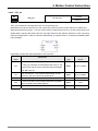
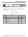
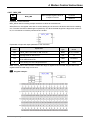
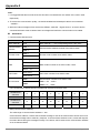
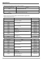
COM1(RS-232)
COM1, RS-232 communication port possessed by PLC module, supports Modbus protocol and could serve
as Modbus master (supporting MODRW, RS instructions) or slave to upload and download programs,
monitor PLC device, and connect human-machine interface and etc.
COM1 Pin Definition:
Pin
Signal
Description
1, 2
+5V
5V power positive pole
3
GND
Grounding
4
Rx
Receiving data
5
TX
Sending data
6
GND
Grounding
7
NC
Reserved
8
GND
Grounding
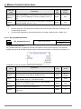
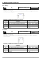
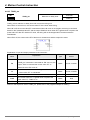
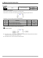
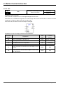
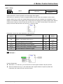
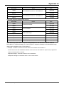
COM2(RS-485)
COM2, RS-485 communication port supporting Modbus protocol, is the hardware port commonly used by
motion control module and PLC. The motion control module or PLC can be accessed through different node
ID. Their node ID must be different with each other. If COM2 is used by PLC, 10MC could be regarded as
Modbus master or slave. If COM2 is used by motion control module, 10MC could only serve as Modbus
slave to download CANopen motion control network configuration, program, G-codes and monitor devices.
COM2 Pin Definition:
Pin
Signal
Description
1
+
Signal+
2
_
Signal-
3
SG
Grounding
Note: Please refer to appendix A for more details on Modbus.
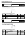
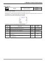
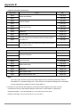
CANopen Bus Interface
There are two RJ45 ports for CANopen bus interface and the standard CAN communication cable
(TAP-CB03/TAP-CB05/TAP-CB10) is needed for user to create a reliable motion control network
conveniently and quickly. CAN bus need be added with two terminal resistors in its two terminals to
constitute the network and Delta supplies the standard terminal resistance module (TAP-TR01). There are
two terminal resistors enclosed in the package of 10MC product.
2-2
Pin
Signal
Explanation
1
CAN_H
Signal+
2
CAN_L
Signal-
3
CAN_GND
Grounding
4
RESE_1
Reserved
5
RESE_2
Reserved
6
CAN_SHLD
Shielded cable
7
CAN_GND
Grounding
8
RESE_3
Reserved
DVP-MC operating manual
2. System Function
Note: DVP10MC11T provides two RJ45-type CAN port to make a daisy-chain topological structure in the two
ends of the bus. One of RJ45 ports is left for connection of terminal resistor.
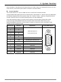
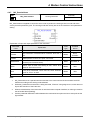
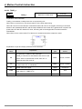
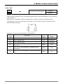
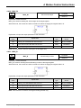
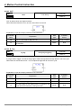
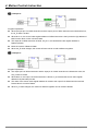
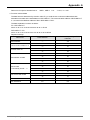
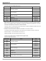
Encoder Interface
The encoder interface is a 15-pin D-SUB connector connected to the external encoder.
It supports differential signal input with max work frequency 1MHz (250Kx 4 = 1MHz for per input). Meanwhile,
this interface integrates two kinds of power output: 24V(500mA)and 5V(500mA) to supply the power to
encoder. And thus users do not need to prepare power for encoder additionally.
User could read D6513 (H9971) in motion control module to check the pulse number that encoder
receives through sending Modbus instruction and also could create virtual master axis by using
DMC-ExternalMaster instruction in motion program. Rotation of slave axis can be controlled by using
encoder to receive the pulse number.
1
A+
2
A-
10
B+
Differential signal of
11
B-
Incremental encoder
4
Z+
5
Z-
7
+24V
+24V encoder power
8
GND
Grounding for +24V and +5V
15
+5V
+5V encoder power
3
Reserved
Reserved
6
Reserved
Reserved
9
Reserved
Reserved
12
Reserved
Reserved
13
Reserved
Reserved
14
Reserved
Reserved
DVP-MC operating manual
Explanation
15-Pin SUB-D figure
1
5
10
15
11
Definition
6
Terminal No.
2-3
2. System Function
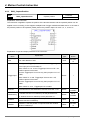
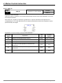
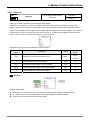
Ethernet communication port
Ethernet communication port supporting Modbus TCP protocol is possessed by motion control module.
CANopen Builder in the PC can download CANopen network configuration, motion control program, cam
curves and G codes and also can monitor devices via Ethernet communication port. DVP10MC11T
only serves as slave and could be accessed by maximum 4 masters in Ethernet network. Ethernet
communication port supports auto jumper function. It can be directly connected to computer or switchboard
without specially handling wire jumper. The LED indicator in the communication port displays Ethernet
current connection status so that user can judge the connection status quickly accordingly.
Terminal No.
Definition
Explanation
1
Tx+
Positve pole for transmitting data
2
Tx-
Negative pole for transmitting data
3
Rx+
Positve pole for receiving data
4
--
N/C
5
--
N/C
6
Rx-
Negative pole for receiving data
7
--
N/C
8
--
N/C
RJ -45 figure
Note: Modbus TCP can be referred to in appendix B.
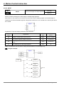
2.1.2.
System Construction Structure
DVP10MC11T consists of two function modules: PLC module and MC motion control module. PLC module is
similar to Delta DVP-SX2 MPU and motion control module supports motion control function based on
CANopen. The two modules utilize the independent processor to process the complicate motion control task
and a large quantity of logic operation in parallel to enhance the work efficiency.
Illustration of the internal structure of DVP10MC11T:
2-4
DVP-MC operating manual
2. System Function
PLC Module
The PLC module built in DVP10MC11T is identical to DVP series of PLC products. User could utilize the
WPLSoft or ISPSoft software to edit the program, conduct the monitoring and make a connection with the left
and right I/O extension and etc. The following is its functions.
¾
CPU specification: 32- bit CPU with the built-in instruction for 32-bit multiplication and division
operation.
¾
In terms of program capacity, devices and instructions
y
y
y
y
¾
Compatible with SX2/ES2/EX2 MPU series of programs; program space: Max 16K Step
Fast-speed execution of instruction ( Basic instruction: 0.35us~1us, MOV instruction< 5us)
The application instruction library is identical to SX2/ ES2/EX2 series
Max 10000 D devices and 2112 latched areas.
Communication devices
y COM1(RS232)communication port
y COM2(RS485)communication port
y Run/Stop switch can control the program to run or stop
¾
Extension module
y Max 7 high-speed extension modules in the left side and 8 extension modules in the right are
available
y The temperature modules like PT/TC supports the function of automatic adjustment of PID
temperature
y Max 240 input points and 240 output points for digital extension module.
¾
Other functions
y Providing user with the special identification code, subprogram password protection and the
limit of the time for inputting the wrong main password
y The built-in DELTA Q-Link communication protocol expedites to refresh HMI screen.
y For more details on the functions of PLC modules, please refer to the operating manuals
(Programming) of DVP-ES2/EX2/SS2/SA2/SX2.
MC Motion Control Module
The MC motion control module in DVP10MC11T controls the servo drive to complete the high-speed, precise
and high-efficiency control task via CANopen bus. DVP10MC11T makes the complicate CANopen
communication packaged and users do not need to know CANopen communication principle except to do the
simple setting and edit the motion control program through CANopen Builder software to accomplish the
complicate motion control. Therefore, it saves a lot of time for user to learn and shortens the lead time to
develop products and speeds up the products to be marketed
The major functions of the motion control module of DVP10MC11T are listed below.
¾
Supporting motion control instructions
y
y
y
y
¾
Logical instruction
Single-axis motion instruction
Multi-axis motion instruction
Typical application instruction
High-speed input point and output point
y Supporting 8 high-speed digital input points (I0~I7) with interruption function
y Supporting 4 high-speed digital output points (Q0~Q3)
DVP-MC operating manual
2-5
2. System Function
¾
Supporting G code
y Supporting standard G code and supporting the dynamic download of G code; G code is
executed while being downloaded in order to accomplish the complicate objects processing.
y Capable to debug the G code in the way of a single step or fixed point through CANopen Builder
software
y CANopen Builder software provides the function of preview of G codes so that user could
conveniently judge if the input G codes are correct or not.
¾
Supporting electronic CAM
y Supporting to call the specified cam curve through CANopen Builder software so as to edit the
cam curve.
y Supporting the application instruction of typical technology such as rotary cutting, flying shear.
Users do not program the cam curve except to input the crucial technological parameters so that
the cam curve will be reflected automatically in the inner of the instruction. And thus it will
reduce a lot of work load for user to develop the project.
¾
Supporting E-gear
¾
Program capacity
y Providing max 1M bytes for the program space, max 12K Fbs program editable
y Max 6000 rows of G codes storable.
y Max 16 electronic cam curves editable and max 2048 key points storable.
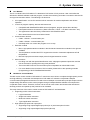
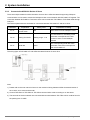
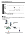
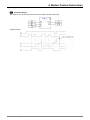
2.1.3.
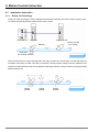
System Extension
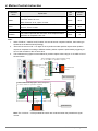
DVP10MC11T can be connected with extension modules on both its left side and right side.
The extension module connected to the left side of DVP10MC11T
DVP10MC11T can be connected with CANopen, DeviceNet master and high-speed modules with analog
quantity like DVP04AD-SL on its left side. Max 7 high-speed modules are allowed to connect to the left side of
DVP10MC11T.
DVPDNET
DVP10MC
D e vi ce N e t/C AN o p e n ma ste r a n d
th e h i g h -sp e e d AIAO mo d u l e s
l i ke D VP0 4 AD -SL. . . . . .
S/S
I0
I1
I2
I3
I4
I5
I6
I7
UP
ZP
Q0
Q1
Q2
Q3
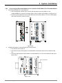
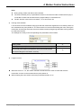
The extension module connected to the right side of DVP10MC11T
DVP10MC11T can also be connected with all Slim series of extension modules with the digital quantity of
max. 240 input points and 240 output points in its right side. Besides, max 8 special modules with non-digital
quantity such as analog-quantity module, temperature module, pulse module and etc. can be connected to
the right side of DVP10MC11T.
The number of digital input/ output point is reflected with X and Y and the functions are as follows.
2-6
DVP-MC operating manual
2. System Function
The number of input/ output point: (Octal)
X20 ~ X27......, X70 ~ X77, X100 ~ X107...
Y20 ~ Y27......, Y70 ~ Y77, Y100 ~ Y107...
Note: The number of digital points of the digital-quantity extension module on the right of DVP10MC11T starts
from 20. Suppose that the input point for the first digital-quantity extension module starts from X20 and output
point starts from Y20. The numbers of input point and output point are added by 8’s multiple; it is counted as 8
points if the number is less than 8.
The number of special modules
The extension modules on the right side of DVP10MC11T like analog-quantity module, temperature module
and pulse module are called special modules. The number of the first special module on the right side of
10MC is 0; the number of the second one is 1, and so on. PLC module could access the special module
according to such serial number through executing FROM/TO instruction.
AIAO and DIDO
……
DVP-MC operating manual
2-7
2. System Function
2.2. The internal devices
2.2.1.
The internal devices of PLC module
See appendix E on the internal devices of PLC in DVP10MC11T
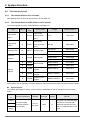
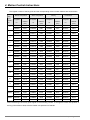
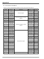
2.2.2.
The internal devices of MC motion control module
The internal devices of motion control module in DVP10MC11T:
Type
Device
Data
type
I
BOOL
Device name
external input
point
I0~I7
0400~0407
Q0~Q3
0500~0503
M0~M1535
0800~0DFF
M1536~M4095
B000~B9FF
D0~D4095
1000~1FFF
D4096~5999
9000~976F
D7000~D24575
9B58~DFFF
D6000~D6226
9770~9852
D6250~D6476
986A~994C
D6500~D6518
9964~9976
D24576~D28671
E000~EFFF
D28672~D45055
2000~5FFF
High-speed
High-speed
output
Q
BOOL
external output
point
Auxiliary relay
M
BOOL
Auxiliary relay
Special
register
Modbus address
High-speed
High-speed
input
General
register
Range
D
WORD
D
WORD
D
WORD
D
WORD
D
WORD
D
WORD
Data register
GPIO register
Special data
register
Axis parameter
register
CAM key point
register
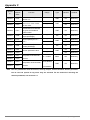
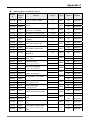
Note: Please refer to appendix C for the explanation of the corresponding content of axis parameter register.
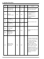
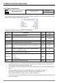
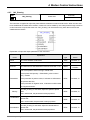
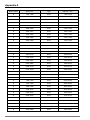
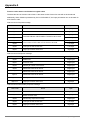
Special register
The special data register of motion control module of DVP10MC11T has its special functions as shown
below.
Special
D
Function explanation
Attribute
Data type
latched
This area is for data exchange
D6000
…
D6226
2-8
Remark
The area of data
exchange between
PLC and MC
PLC: R
MC: R/W
UINT
N
between PLC and MC, MC
writes the data into this area
and PLC reads the data in this
area.
DVP-MC operating manual
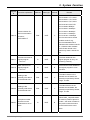
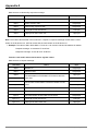
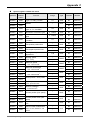
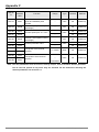
2. System Function
Special
D
Function explanation
Attribute
Data type
latched
This area is for data exchange
D6250
The area of data
…
exchange between
PLC and MC
PLC: R/W
MC: R
UINT
N
D6476
D6500
Current scanning
time for
DVP10MC(unit: us)
for DVP10MC (unit:
us)
between PLC and MC, PLC
writes the data into this area
and MC reads the data in this
area.
The time needed for motion
R
UINT
N
R
UINT
N
Max. scanning time
D6501
Remark
control program to scan the
last time.
Max. time needed for motion
control program to scan once.
It is in hexadecimal. The part
D6502
The major revision of
DVP10MC firmware
R
UINT
N
to the left of decimal point is
high byte and the part to the
right of decimal point is low
byte. If the read value is
0101H, it means the current
major firmware is V1.01
revision.
It is in hexadecimal. The part
D6503
D6504
D6505
The minor revision of
DVP10MC firmware
Firmware revision of
PLC module
The exchanged data
length when MC =>
PLC (unit: word)
R
UINT
Y
R
UINT
Y
R
UINT
Y
length when PLC =>
MC (unit: word)
exchanged data
when MC => PLC
DVP-MC operating manual
to PLC by MC with word as its
unit.
The length of the data written
R
UINT
Y
R
UINT
N
The check code of
D6507
Firmware revision of 10MC
PLC module
The length of the data written
The exchanged data
D6506
to the left of hexadecimal point
is high byte and the part to the
right of hexadecimal point is
low byte. If the read value is
0101H, it means the current
min firmware is V1.01 revision.
to MC by PLC with word as its
unit.
The check code of the data
which MC writes to PLC.
2-9
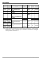
2. System Function
Special
D
Function explanation
Attribute
Data type
latched
R
UINT
N
The check code of
D6508
exchanged data
when PLC => MC
Remark
The check code of the data
which PLC writes to MC.
1. When D6509 value = 0
D6509
Setting of
RUN/STOP switch
R/W
UINT
N
R
UINT
N
RUN/STOP switch is
disabled.
2. When D6509 value = 1,
RUN/STOP switch is
enabled.
Low word of
D6511
DVP10MC status
word
Status word of MC module
High word of
D6512
DVP10MC status
word
R
UINT
N
R
UDINT
N
Low word of
D6513
feedback pulse
number of the
encoder
High word of
D6514
Feedback pulse number of the
encoder
feedback pulse
number of the
encoder
7: Program is being executed.
0: Execution of program stops
16: System reset which is
equivalent to that 10MC is
powered on again.
Motion program
6515
2-10
RUN/STOP and
system reset
R/W
UINT
N
When the motion control
program of 10MC is running,
write 0 to D6515 to stop the
program being executed.
Afterwards, the motion control
program can not be executed
again unless 7 is written to
D6515 after pressing the
Reset key.
DVP-MC operating manual
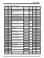
2. System Function
Special
D
Function explanation
Attribute
Data type
latched
Remark
b3~b0=0000: 7,E,1,ASCII
b3~b0=0001: 7,O,1,ASCII
b3~b0=0010: 7,N,1,ASCII
b3~b0=0100: 8,N,2,RTU
b7~b4=0000: 9600bps
b7~b4=0001: 19200bps
b7~b4=0010: 38400bps
Communication ID
D6516
D6517
and communication
format of
DVP10MC11T
Current scan time for
logical program
(Unit: us)
b7~b4=0011: 57600bps
R/W
UINT
Y
b15~b8 are used to set the
modbus node ID, e.g.
b15~b8=00000001which
indicates that modbus node ID
is 1, likewise other modbus
node ID are named in the
same way. Note: b stands for
bit.
The time needed for the
R
UINT
N
Max. scan time for
D6518
D6519
logical program
(Unit: us)
Setting of the
quantitiy of D device
in the latched area
quantitiy of M device
in the latched area
logical program to carry out
scanning currently.
The maximum time needed for
R
UINT
N
the logical program to scan
one time.
The start D device in the
R/W
UINT
Y
latched area is D7000; the
quantity is specified by D6519;
range: 0~3000.
The start M device in the
Setting of the
D6520
b7~b4=0100: 115200bps
R/W
UINT
Y
latched area is M3000; the
quantity is specified by D6520;
range: 0~1000
When DMC_ CapturePosition
D6527
The pulse number
that servo motor
feeds back to servo
drive
DVP-MC operating manual
R
DINT
N
is used for position capture in
mode 1, the value of D6527 is
the pulse number that servo
motor feeds back to servo
drive.
2-11
2. System Function
Special
D
Function explanation
Attribute
Data type
latched
Remark
When DMC_ CapturePosition
The pulse number
D6529
received at the
interface of the
encoder
R
DINT
N
uses I0 for position capture in
mode 10, the value of D6529
is the pulse number received
at the interface of the encoder
of 10MC.
0: Axis alarm is not detected.
The instructions related with
the alarm axis can still be
executed when the axis
alarms.
D6532
Axis alarm detection
R/W
UINT
N
1: When the axis alarms,
the alarm axis enters the state
of ErrorStop and the motion
instructions related with the
alarm axis stops being
executed.
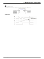
Note: The areas for exchanging the data between MC and PLC are D6000~D6226, D6250~D6476.
D6000~D6226 are where MC writes the data and PLC reads the value of the register; D6250~D6476 are
where PLC writes the data and MC reads the value of the register.
The principle figure is displayed below.
Write into
Read by
D6000~D6226
MC
PLC
Read by
Write into
D6250~D6476
2-12
DVP-MC operating manual
2. System Function
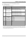
Status word in DVP10MC
D6511 and D6512 are the status words of MC module and the following is the specific explanation:
Bit
The implication when each bit in
Device
D6511 is 1
How to deal with
DVP10MC11T is in error mode,
Bit0
motion control program is terminated
by accident.
DVP10MC11T is in mode of
Bit1
configuration and the configuration
data is being downloaded.
Bit2
Node list is empty and slave has not
been configured.
Bit3
The configuration that the upper
computer downloads is invalid
Press RESET button to restart DVP10MC11T
No need of action but wait the download is finished
and then 10MC will automatically restore to run.
Redownload the configuration data to the controller
after the network is configured through CANopen
Builder software.
Check if the configured data is wrong and
redownload after revising configuration.
1. Check if CANopen bus connection is normal
Bit4
Buffer area sending data is full
2. Check if the baud rate of CANopen bus master is
identical to that of slave.
3. Check if the two ends of CANopen bus have
been connected with terminal resistors.
1. Check if CANopen bus connection is normal
Bit5
Buffer area receiving data is full
2. Check if the baud rate of CANopen bus master is
identical to that of slave
3. Check if the two ends of CANopen bus have
been connected with terminal resistors.
Bit6
Power supply for DVP10MC11T is
insufficient.
Check if power supply for DVP10MC11T is normal.
Bit7
Internal storage operation error
Repower on; return to factory for repair if the error
still exists
Bit8
GPIO operation error
Repower on; return to factory for repair if the error
still exists
Bit9
SRAM operation error
Repower on; return to factory for repair if the error
still exists
Bit10
Some slave in CANopen network is
offline
Check if CANopen bus connection is normal.
Bit11
The program in MC is running.
--
Bit12
The synchronous cycle set is too
small
Enlarge the synchronous cycle.
Reserved
Reserved
Bit13~
Bit15
Note: D6512 is reserved for further development in the near future.
DVP-MC operating manual
2-13
2. System Function
2.3. System Work Principle
2.3.1.
Axis Parameter Setting
MC function module in DVP10MC11T is mainly applied to control over drive axis. Therefore, the setting of
parameter of every drive axis is very crucial and the following is the main parameters to be set up.
Node ID: axis number (which is the node address of servo drive in CANopen network);
Axis Type: Linear, Rotary;
Ramp Type: To set the feature type in the process in which axis increases and decreases speed
Software Limitation: To limit the maximum and minimum position of motion controller;
Servo Gear Ratio Setting: The ratio decides how many units are needed for one circle the axis
rotates;
Homing: It is used to set the mode and speed for homing;
Maximum Value: To set the max. velocity, acceleration and deceleration of the axis;
Cyclic communication data: To specify the servo drive parameters to be read by 10MC
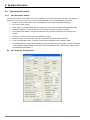
Axis parameters are mainly used for setting the feature of the axis and the setting could be completed
in the CANopen Builder software. The newly set axis parameters will be effective only after they are
downloaded to DVP10MC11T
2-14
Axis Parameter Configuration
DVP-MC operating manual
2. System Function
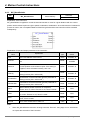
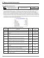
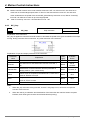
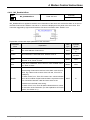
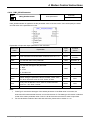
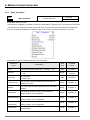
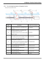
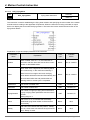
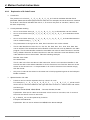
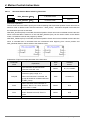
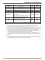
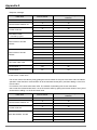
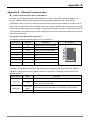
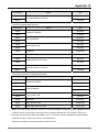
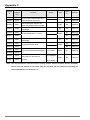
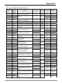
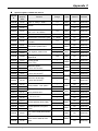
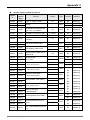
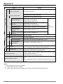
Description of Axis Parameter:
Serial
No
Parameter Name
1
Node-ID
Function
Axis number; range:1-16
Data Type
Default
Value
UINT
-
String
-
“Node-ID” is the CANopen node address of servo drive.
2
Name
Axis name
"Name" is the word commented on servo drive by software, which is only used for naming the servo
drive without actual meaning.
3
Axis type
Axis type: linear axis/ rotary axis
-
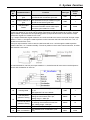
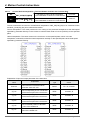
Rotary axis
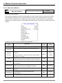
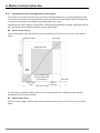
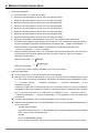
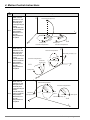
Linear Axis:
Notes for Linear Axis Model:
P1
Positive Limit
P2
Negative Limit
Servo Position
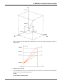
Rotary Axis :
Rotary Axis Mode(“Modulo”: 360)can not see the photo
Notes for Rotary Axis Mode:
P1
Positive Limit
P2
Negative Limit
Servo Position
R
Home Position
Z
Axis of servo motor
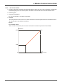
Difference between linear axis and rotary axis
The rotary axis regards modulo as its cycle, which is the difference between linear axis and rotary axis.
The position of terminal actuator of linear axis is 500 and the corresponding position of rotary axis is 140
which is the remainder of 500 divided by modulo (360).
4
Modulo
DVP-MC operating manual
The cycle used for equally dividing the
actual position of the terminal actuator.
REAL
360
2-15
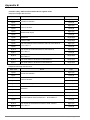
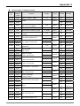
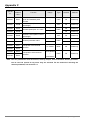
2. System Function
Serial
No
Parameter Name
Function
Data Type
Default
Value
BOOL
0
5
Software Limitation
Enable software limitation;
If it item is not selected, The maximum/
minimum position of axis which software
limits is invalid.
If selected, the maximum/
minimum position of axis limited by
software is valid.
6
Maximum Position
The max. position of axis limited by
software
REAL
-
7
Minimum Position
The mini. position of axis limited by
software
REAL
-
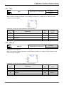
8
Acceleration Type
Trapezoid/Sinus
-
Trapezoid
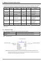
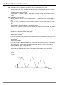
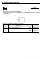
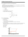
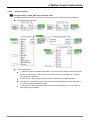
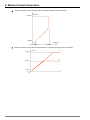
Servo motor presents the features in process of acceleration and deceleration while DVP10MC11T is
controlling servo drive.
Trapezoid:
Sinus:
9
Unit Numerator
To set the pulse quantity needed when
motor rotates for one circle by adjusting
unit numerator and the denominator.
10
Unit Denominator
To set the pulse quantity needed when
motor rotates for one circle by adjusting
unit numerator and the denominator.
UINT
1
11
Increment
How many pulses are needed when servo
motor rotates for one circle.
UINT
10000
UINT
128
Adjusting the Unit Numerator and Unit Denominator parameters is to set the electronic gear proportion
of servo drive. Electronic gear proportion is to set how many pulses servo drive receives while servo
motor rotates for a circle.
The resolution of A2 servo drive motor is 1280000 pulses/ circle;
Suppose the value of parameter 11 is N, N* (Unit Numerator/ Unit Denominator)=1280000
2-16
DVP-MC operating manual
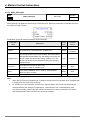
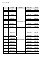
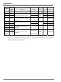
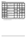
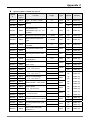
2. System Function
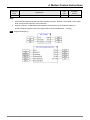
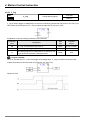
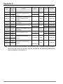
Serial
No
Parameter Name
12
Input rotations of
gear
13
Output rotations of
gear
14
Unit per output
rotation
Data Type
Default
Value
This parameter and Output rotations of
gear decide the mechanism gear ratio.
UINT
1
This parameter and Input rotations of gear
decide the mechanism gear ratio.
UINT
1
The corresponding position units which
the terminal actuator moves while output
end of the gear rotates for a circle.
UINT
10000
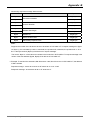
Function
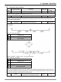
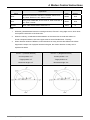
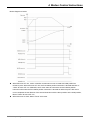
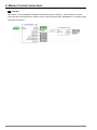
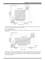
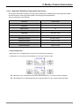
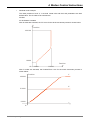
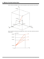
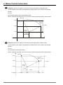
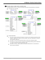
As illustrated below, Input rotation of gear =1, Output rotation of gear =2, it means the input mechanism
of gear box rotates for one circle and the output mechanism of gear box rotates for 2 circles. “Unit per
output rotation” represents the corresponding position (units) that ball screw moves while the output
mechanism of gear box rotates for one circle.
E.g. If output mechanism of gear rotates for one circle and ball screw moves 1mm and "Unit per output
rotation" is set to 1, through the relative position motion instruction the ball screw will move 1 unit, i.e.
the ball screw will move 1mm;
If Unit per output rotation is set to 1000, the ball screw will move 1 unit through the relative position
motion instruction, i.e. 1/1000mm actually. The unit of position in the motion control instruction, G codes
and electronic cam is Unit.
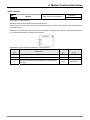
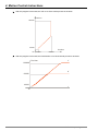
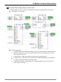
As mentioned above, set Unit per output rotation to 1, the ball screw will move 50 mm at the speed of
1mm/s and acceleration of 2mm/ s2.
Homing Mode
Servo drive is set to homing mode; range:
1~ 35.
See appendix D for more details.
UINT
1
The first-phase
speed for homing
The speed from returning to zero point to
finding the home switch;Unit: rpm,
setting range: 1-2000 rpm
UDINT
20
The second-phase
speed for homing
The speed from finding the home switch
to reaching the mechanical home;Unit:
rpm, setting range: 1-500 rpm
UDINT
10
17
Max. Velocity
The available max. velocity; (Unit: unit)
REAL
10000
18
Max. Acceleration
The available max. acceleration; (Unit:
unit)
REAL
10000
15
16
DVP-MC operating manual
2-17
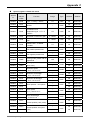
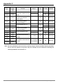
2. System Function
Serial
No
Parameter Name
19
Max.Deceleration
Function
The available max. deceleration; (Unit:
unit)
Data Type
Default
Value
REAL
10000
Parameters 17~19 are used in the specific situation. E.g. The velocity, acceleration and deceleration of
G0 in instruction CNC; the velocity, acceleration and deceleration at which slave enters the state of
meshing with the master axis when Cam in; the velocity, acceleration and deceleration at which slave
follows the master to move when Gear in.
20
Position
The current position of servo drive
(Unit: Pulse)
DINT
21
Velocity
The current speed of servo drive
(Unit: 0.1 rpm)
DINT
22
Torque
The current torque of servo drive
( Permille of the rated torque)
INT
Above three parameters are used for setting DVP10MC11T to adjust PID of servo drive
23
Current
24
User defines
parameter
The present current of servo drive
( Permille of the rated current)
INT
Servo drive parameters customized by
users
“User defines parameter” is the servo drive parameter to be read. Its length is specified according to the
data type of the read parameter.
The byte parameter length is 1; the word parameter length is 2 and double-word parameter length is 4.
The method of calculating sub-index and index of the servo drive parameter is shown below:
Index= Servo drive parameter (Hex) + 2000 (Hex), Sub-index=0
For example: The index of servo drive parameter P6-10:
2000+060A (P6-10 hex.)=260A; sub-index: 0.
Cyclic communication data can be selected by users. The data length selected can not exceed 8 bytes
which can be calculated by computer automatically. The data length of position, speed, torque and
current are 4 bytes, 4 bytes, 2 bytes and 2 bytes respectively. The current value of cyclic communication
data selected by user can be read by the special registers related with axis. See appendix C for more
details.
2-18
DVP-MC operating manual
2. System Function
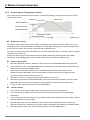
2.3.2.
Motion Program Execution Principle
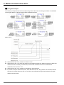
DVP10MC11T consists of two function modules: PLC module and MC motion control module. To enhance
the work efficiency, the two modules handle the logic tasks and motion control task respectively. User could
edit the program for the PLC module through ISPSoft and WPLSoft software to achieve logic control function,
while, to achieve motion control function, CANopen Builder software is necessary for programming.
The way of execution of motion control program is basically same as that for PLC program through three
stages of input capture, program execution, output refresh. But motion control program is executed on basis
of the synchronized cycle which is the cycle for updating the control and status data between motion
controller and servo drive. In one synchronized cycle, motion controller needs to capture all data related with
control program including the status data returning from servo drive, then to execute the motion program and
finally output the data of operation result to each register and control data to all servo drives. All these actions
have to be completed in one synchronized cycle.
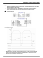
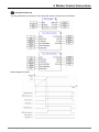
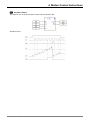
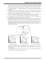
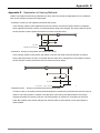
When DVP10MC11T is connected with multi-servo drives, 10MC can achieve synchronization of multi-servo
drives through sending out synchronous signals in the method of broadcast. Servo drives receive control
data that 10MC sends out. These data are not effective immediately till the synchronous signals reach the
servo drives to realize the synchronization of multi-servo drives.
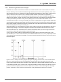
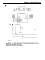
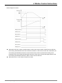
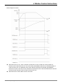
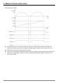
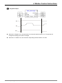
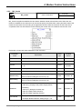
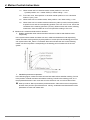
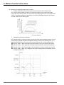
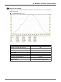
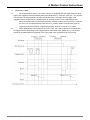
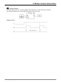
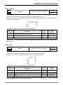
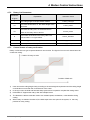
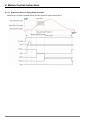
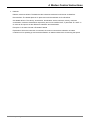
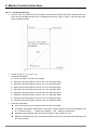
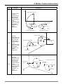
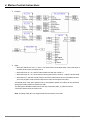
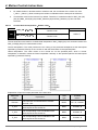
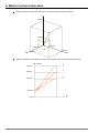
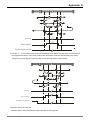
As 2.2.1 figure is shown, 10MC is connected with 4 servo drives and T is the synchronized cycle. In the
synchronized cycle, 4 servo drives receive the control data at different time (t1, t2, t3, t4) respectively but the
control data do not get effective immediately. The control data will get effective while the servo drives receive
the SYNC signals.
Figure 2.2.1
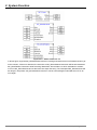
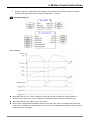
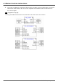
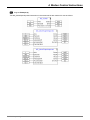
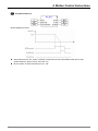
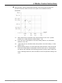
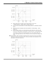
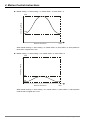
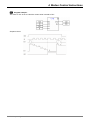
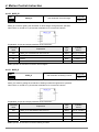
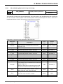
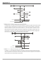
Figure 2.2.2 is an example of motion program (using MTL language). When motion control module detects
M2=on in a synchronized cycle, MC_MoveAbsolute instruction starts to be executed. In this scan cycle,
motion control module sends a piece of position control data to servo drive but M20 (Done bit) will not turn on.
In the following several cycles, motion control module will constantly send the data to servo drives to control
positions till the actual positions that servo drives feedbacks to motion control module approach the target
position. At that time, “Done” bit M20=on and execution of MC_MoveAbsolute instruction is finished.
DVP-MC operating manual
2-19
2. System Function
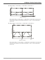
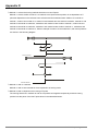
Figure 2.2.2 Motion control task list
In above figure, suppose MC_MoveAbsolute instruction is being executed but has not finished execution yet.
At the moment, if M3=on is detected, the execution of MC_MoveAbsolute instruction will be terminated and
MC_MoveRelative instruction starts executing. Meanwhile, Abort bit M21=on which indicates an accident
occurs in MC_MoveAbsolute and so the instruction stops executing. The interrupted MC_MoveAbsolute will
be always in stop status. MC_MoveAbsolute instruction can be executed again unless M2 turns Off Æ On
once again.
2-20
DVP-MC operating manual
2. System Function
2.3.3.
CNC Function
DVP10MC11T, a multi-axis motion controller, supports the standard CNC function and can execute G codes
dynamically and statically to achieve the simple numerical control of machine tool. Besides, it could also be
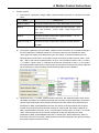
applied to the occasions where G codes are used to locate and path planning.
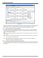
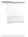
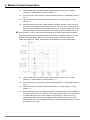
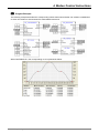
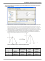
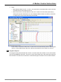
CANopen Builder software provides CNC G code editing function; user could edit G codes in the CNC editor
or import the G codes switched by other design software into this editor. When G codes are input in the code
list, the two-dimension chart of G codes is output in the preview window.
The software interface of CNC editor is shown as figure 2.3.1
Figure 2.3.1
DVP10MC11T could execute G codes in two ways. One is the way of statically downloading all G codes to
controller for run. The other one is dynamic way. When complicate objects are processed, the quantity of G
codes needed is quite huge and so the controller could not store all G codes. Then the dynamic way is
adopted and the G codes could be executed while being downloaded. DVP10MC11T provides the buffer
area which could store 100 rows of G codes to store the G codes the upper computer sends. In way of
dynamic download, the G codes the upper computer sends will not be stored and will be dumped after they
are executed. If the G codes downloaded need be latched when power off, user should adopt the way of
static download.
After G code editing is finished, it should be called for use in the motion control program. NC document is
called for use via DMC_NC in motion control program. The usage of DMC_NC can be seen in the relevant
instruction introduction. The input parameter NcTableID is to choose the NC document number to be
executed. CMC editor could edit 8 NC documents at the same time.
If user wants to execute G codes in dynamic way, the current chosen NC document number should be set to
0. At this moment, the controller will wait the upper computer to send G codes and the G codes will be
executed while being sent.
DVP-MC operating manual
2-21
2. System Function
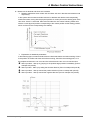
Figure 2.3.2
CNC editor provides the function of debugging of the current G codes so that user only need preset the target
position of the G codes to be executed. Also, CNC editor can provide the function of one single -step
execution of the current G-code document to ensure the correctness of debugging of G codes.
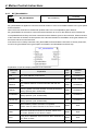
2.3.3.1.
CNC Program Downloading and Debugging
When users use the motion control program to call CNC program, the value: 0 of parameter NcTableID of
DMC_NC indicates to download CNC program in dynamic way. CANopen Builder provides the following
tools for downloading and debugging
: Start to download dynamically CNC program which will be executed after controller receives the first
program.
: Make the current CNC program run and stop at the place selected by cursor, which is convenient for
user to debug the current CNC program.
: Single -step execution of CNC program; execute one row every time and when the current row
of program is executed, it will be displayed in yellow.
2.3.3.2.
The Protocol for Dynamic Download of CNC Program
DVP10MC11T supports the open protocol for download of CNC program. User could autonomously develop
the process software in PC end to produce G codes and dynamically download the codes to DVP10MC11T
for execution.
2-22
DVP-MC operating manual
2. System Function
2.3.3.3.
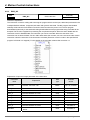
Message Format
The following is the format of the Modbus packet of CNC program downloaded dynamically.
Request message format:
0
1
2…n-1
n…n+1
Address
Function Code 0x7A]
G-Code string
Parity
Address: The communication node ID of DVP10MC11T, default: 02
Function Code: Function code, 0x7A indicates to download CNC programs dynamically.
G-Code String: A complete row of CNC program character string presented in ASCII code value with the
symbol of “Enter” in the end.
For instance, suppose that the address of DVP10MC11T is 02, the G code character string to be download is
N00 G00 X10.0 Y10.0.
The request message (Hex) will be 027A4E303020473030205831302E30205931302E300D8E57
Explanation of message:
027A: Node ID and function code
4E303020: N00 [A blank space]
47303020: G00 [A blank space]
5831302E3020: X10.0 [A blank space]
5931302E300D: Y10.0 [A blank space]
8E57: CRC parity
Response message format:
0
1
2
3-4
Address
Function Code [0x7A]
ResposeCode
Parity
Address: The node ID of DVP10MC11T, default :02.
Function Code: Function code, 0x7A indicates to download CNC program dynamically.
Response Code:
00
Illegal function code
01
Success
02
In process of transmission
04
Illegal command
05
Time-out
06
Illegal length of the message received
07
Equipment is busy
08
The buffer area receiving data is full
DVP-MC operating manual
2-23
2. System Function
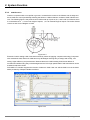
2.3.4.
CAM Function
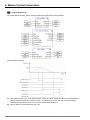
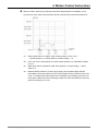
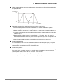
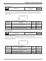
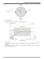
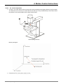
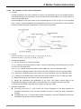
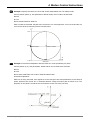
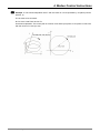
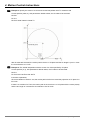
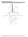
CAM is a component with curve profile or grooves. It transmits the motion to the follower near its edge and
the rack will turn around periodically following the follower. CAM mechanism consists of CAM, follower and
rack. The following figure is the profile chart of CAM made up of point A, B, C, and D. AB' is a follower which
is connected to rack. δ4 is an inner angle of repose; δ2 is an external angle of repose. The radius of base
circle is r0 and S is the diagram of CAM.
Figure 2.3.3
Electronic CAM is analog CAM of mechanical CAM by means of applying computer technology. Compared
with mechanical CAM, Electronic CAM has many advantages of being easy to design and modify; cost
saving; higher efficiency and preciseness. Because electronic CAM is analog CAM, these defects of
mechanical CAM like being easy to be damaged and not fit for high-speed rotation and transmission can be
avoided for electronic CAM.
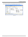
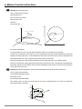
DVP10MC11T controller supports the function of electronic CAM. User can edit the CAM curve in the CAM
editor provided by CANopen Builder as follows.
Figure 2.3.4
2-24
DVP-MC operating manual
2. System Function
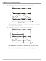
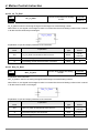
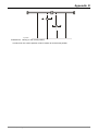
After CAM curve is finished editing, it should be called for use in the motion control program where
MC_CamTableSelect and MC_CamIn are included together as figure 2.3.5 shows.
Figure 2.3.5
DVP-MC operating manual
2-25
3. System Installation
3. System Installation
This chapter focuses on the instructions of electrical specification and system installation. For the details of
peripheral devices, please refer to the user manual enclosed with the product or log on the website:
http://www.delta.com.tw.
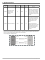
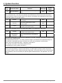
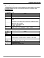
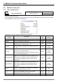
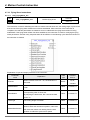
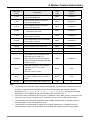
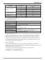
3.1. Electrical Feature
Electrical specification
Item
Content
Voltage
24 VDC(-15% ~ +20%)
Current
2.5 A/30 VAC
Electrical
isolation
500 VDC(Secondary-PE)
Consumption
power
Max 8W
Vibration/shock
immunity
Standard:IEC61131-2,IEC 68-2-6 (TEST Fc)/IEC61131-2 & IEC 68-2-27 (TEST Ea)
Interference
immunity
Environment
Weight
Static electricity: 8KV Air Discharge
EFT: Power Line: 2KV, Digital I/O: 1KV
RS: 26MHz ~ 1GHz, 10V/m
Work: 0°C ~ 55°C (Temperature), 50 ~ 95% (Humidity), Pollution level 2
Storage: -25°C ~ 70°C (Temperature), 5 ~ 95% (Humidity)
About 240g
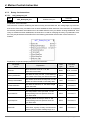
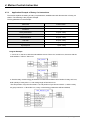
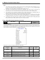
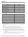
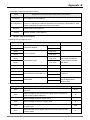
Electrical specification for the input point
Item
Content
Input channel
number
8 channels
Channel type
High-speed digital input type for the 8 channels
Input terminals
Terminal I0, I1, I2, I3, I4, I5, I6, I7
Common terminal
Terminal S/S used for connection of the plus or minus pole of supply power
for the input point
Input type
Sink mode or Source mode
Input delay
2.5µS ( Off ->On ), 5 µS (On -> Off )
Input current
24 VDC, 5mA
Max cable length
The Shielded cable: 500m
The cable without a shield wire: 300m
DVP-MC operating manual
3-1
3. System Installation
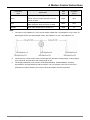
Electrical specification for the output point
Item
Content
Input channel
number
4 transistors for output (Source)
Channel type
High-speed digital output type for the 4 channels
Output terminals
Terminal: Q0, Q1, Q2, Q3
Power voltage for
24 VDC(-15% ~ +20%)#1
output point
Output delay
2µS ( Off -> On), 3µS ( On -> Off )
Max switch
frequency
1KHZ
Resistance: 0.5A/1point (2A/ZP)
Max loading
Inductance: 15W(30VDC)
Bulb: 2.5W(30VDC)
Max cable length
The Shielded cable: 500m
The cable without a shield wire: 300m
#1: UP and ZP must connecte the auxiliary power 24VDC(-15%~20%.
3-2
DVP-MC operating manual
3. System Installation
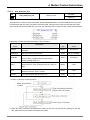
3.2. System Connection
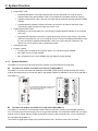
3.2.1.
Power and IO Wiring
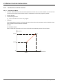
Power input
It is direct current input for DVP10MC11T MPU power and below items should be paid special attention to for
use.
1. The input power voltage is in the range from 20.4 VDC to 28.8VDC and the power is connected to
the two terminals: 24V and 0 and earth terminal is connected to the ground. Besides, please note
that the positive pole and negative pole of the power must not be connected reversely otherwise any
damage on DVP10MC11T may be caused.
2. The earth terminal of DVP10MC11T MPU uses the cable above 1.6mm for grounding.
3. If the time for power-off is too long or power voltage is descended, DVP10MC11T will stop working,
output will turn off and communication with servo drive will also be terminated. DVP10MC11T cannot
make the communication with servo drive any more unless the power restores into normal status.
Safety circuit wiring
DVP10MC11T controls servo drive and any action of its internal device is possible to influence the action of
external mechanical organization. So any malfunction of any device may cause the whole automatic control
system to lose control and even result in personal injury and death. Below protection devices are suggested
for use in power input circuit.
Figure 3.2.1
1 AC power supply: 100~240VAC, 50/60Hz;
2 Fuse for power loop protection;
3 System circuit isolation device: use the switches of electromagnetic contactor and relay as the
isolation devices of system power circuit in case the system is unstable when power supply is
interrupted frequently
4 Power indicator
5 Emergent stop: To prevent sudden status happening, emergent stop button is set to cut system
power once accident occurs;
DVP-MC operating manual
3-3
3. System Installation
6 Delta power module DVPPS02/24VDC ( It is recommended to adopt the power module DVPPS02 for
DVP10MC11T);
7 DVP10MC11T body;
8 Grounding
9 Safety circuit
Wiring of input and output point
Wiring of input circuit
The input signal of input point is direct-current power input in two ways of wiring: Sink mode and Source
mode. The following is the introduction of the two ways.
¾
Sink mode
The feature of Sink mode is that the current flows to the common terminal S/S. See the simplified model
as figure 3.2.2.
S/ S
I0
Figure 3.2.2
The relevant circuit for wiring is shown as figure 3.2.3
Figure 3.2.3
¾
Source mode
The feature of Source mode is that the current flows out from the common terminal S/S. See the simplified
model as figure 3.2.4
Figure 3.2.4
3-4
DVP-MC operating manual
3. System Installation
The relevant circuit for wiring is shown as figure 3.2.5
Figure 3.2.5
Wiring of output circuit
The circuit plate for the transistor output in DVP10MC11T includes the diodes with the protection function of
counter potential. It is sufficient for application of the inductive load at low power and little higher frequency of
On/Off change. In the case of high power or high On/Off change frequency, please additionally connect the
suppression circuit according to the following figure to decrease the interference and prevent over-voltage or
over-heat from damaging the transistor output circuit.
Figure 3.2.6
24V direct current power
Fuse protector for power circuit protection;
Emergent stop button;
Loading for switch, inductance and etc.
9V Zener diode, 5W;
When the power for loading is quite high and On/Off status is switched frequently,
and
will be used
together.
Diode or the equivalent object is used as the diode suppressor. When the power for loading is low,
is in no need for use but
DVP-MC operating manual
.
3-5
3. System Installation
3.2.2.
Connected to ASDA-A2 Series of Servo
There are multiple models for ASDA-A2 series of servo drive. ASDA-A2-●●●●-M supporting CANopen
communication can be used to create the CANopen motion control network with DVP10MC11T together. The
connection between DVP10MC11T and servo drive can be made with TAP-CB03 or TAP-CB05 cable through
CN6 port.
The relevant parameters are set below for connection between DVP10MC11T and servo drive:
Parameter
P1-01
Explanation
Setting of servo
control mode
Setting value
0B
Explanation of Setting
Servo drive is set as CANopen mode
For DVP10MC11T, the setting of this
P3-00
Setting of node ID
Setting range: 1~16
parameter corresponds to the axis
number of servo in the CANopen
network
The corresponding baud rate of the
P3-01
Baud rate
0403
parameter value must correspond to
that of DVP10MC11T.
The wiring figure of DVP10MC11T and ASDA-A2-●●●●-M series of servo drive
Figure 3.2.7
Note:
1) Please refer to the user manual of servo for the method of wiring between ASDA-A2-●●●●-M series of
servo drive, servo motor and encoder.
2) Choose TAP-CB03 or TAP-CB05 or TAP-CB10 communication cable according to on-site status.
3) The two ends of the bus network are connected with terminal resistors TAP-TR01 which could be found in
the packing box of 10MC.
3-6
DVP-MC operating manual
3. System Installation
3.2.3.
1.
Connecting the Extension Module to the Left Side of DVP10MC11T as DeviceNet Master
Connecting DVPDNET-SL to DVP10MC11T
¾ Open the extension module clips on the top left and bottom left of DVP10MC11T and
install DVPDNET-SL along four mounting holes in the four angles of DVP10MC11T as figure 3.2.8.
¾ Press the clips respectively on the top left and bottom left of DVP10MC11T to fix the module tightly
and ensure that their contact is normal.
2
DVPDNET
DVP10MC
S/S
I0
I1
I2
I3
I4
I5
I6
I7
1
UP
ZP
Q0
Q1
Q2
Q3
2
2.
Figure 3.2.8
Installing DVP10MC11T and DVPDNET-SL into the DIN rail
¾ Use standard 35mm DIN rail;
¾ Open DIN rail clips of DVP10MC11T and DVPDNET-SL and then insert the two modules in DIN
rail.
¾ Press the DIN rail clips into DVP10MC11T and DVPDNET-SL to fix the two modules in DIN rail as
figure below.
DVPDNET
DVP10MC
S/S
I0
I1
I2
I3
I4
I5
I6
I7
35mm DIN Rail
UP
ZP
Q0
Q1
Q2
Q3
Figure 3.2.9
DVP-MC operating manual
3-7
3. System Installation
3.2.4.
1.
Connecting the Extension Module (DVP16SP11T) to the Right Side of DVP10MC11T
Connecting DVP16SP11T to DVP10MC11T;
¾ Open the extension module clips on the top right and bottom right of DVP10MC11T and
install DVP16SP11T along four mounting holes in the four angles of DVP10MC11T as figure
3.2.10.
¾ Press the clips on the upper right and bottom right of DVP10MC11T to fix the module tightly
and ensure that their contact is normal.
2
S/S
I0
I1
I2
I3
I4
I5
I6
I7
1
UP
ZP
Q0
Q1
Q2
Q3
D VP -16S P
DVP10MC
2
Figure 3.2.10
2.
Installing DVP10MC11T and DVP16SP11T in DIN Rail
¾ Use standard 35mm DIN rail;
¾ Open DIN rail clips of DVP10MC11T and DVP16SP11T and then insert the two modules in DIN
rail.
¾ Press the DIN rail clips into DVP10MC11T and DVP16SP11T to fix the two modules in DIN rail as
figure below.
D VP10M C
UP
ZP
Q0
Q1
Q2
Q3
35mm DIN Rail
D VP -16S P
S/S
I0
I1
I2
I3
I4
I5
I6
I7
Figure 3.2.11
3-8
DVP-MC operating manual
4. Motion Control Instructions
4.
Motion Control Instruction
4.1. Instruction Table
Class
API
Instruction Name
Function
Page
Singel-axis instruction
Multi-axis instruction
1
MC_MoveAbsolute
Move absolutely
4-8
2
MC_MoveRelative
Move relatively
4-14
3
MC_MoveAdditive
Move additively
4-18
4
MC_MoveSuperImposed
Superimposed motion
4-22
5
MC_MoveVelocity
Velocity instruction
4-27
6
MC_Stop
Stop instruction
4-30
7
MC_PassiveHome
Homing instruction
4-33
8
MC_Power
Power control instruction
4-36
9
MC_Reset
Reset instruction
4-37
10
MC_ReadStatus
Read axis status
4-39
11
MC_ReadActualPosition
Read actual position
4-40
12
MC_ReadAxisError
Read axis error
4-41
13
MC_ReadParameter
Read parameters
4-42
14
MC_WriteParameter
Write parameters
4-43
15
DMC_SetTorque
Set torque
4-44
64
MC_CamTableSelect
Select cam table
4-46
65
MC_CamIn
Cam-in instruction
4-47
66
MC_CamOut
Cam-out instruction
4-66
67
DMC_CamSet
Set cam
4-69
68
MC_GearIn
Gear-in instruction
4-73
69
MC_GearOut
Gear-out instruction
4-75
70
MC-Phasing
Phase shift
4-77
71
DMC-CapturePosition
Capture position
4-80
72
DMC-VirtualAxis
Create virtual axis
4-86
73
DMC-ExternalMaster
Create external virtual master axis
4-88
DVP-MC operating manual
4-1
4. Motion Control Instructions
Class
Logical Instruction
4-2
API
Instruction Name
Function
Page
128
ADD
Addition of 16-bit integer
4-90
129
ADD_DI
Addition of 32-bit integer
4-90
130
ADD_R
Addition of floating number
4-91
131
SUB
Subtraction of 16-bit integer
4-91
132
SUB_DI
Subtraction of 32-bit integer
4-92
133
SUB_R
Subtraction of floating number
4-92
134
MUL
Multiplication of 16-bit integer
4-93
135
MUL_DI
Multiplication of 32-bit integer
4-93
136
MUL_R
Multiplication of floating number
4-94
137
DIV
Division of 16-bit integer
4-94
138
DIV_DI
Division of 32-bit integer
4-95
139
DIV_R
Division of floating number
4-95
140
AND
Logical AND operation
4-96
141
OR
Logical OR operation
4-96
142
XOR
Logical XOR operation
4-97
143
NOT
Logical NOT operation
4-97
144
CTU
Up-counter
4-98
145
CTD
Down-counter
4-100
146
CTUD
Up/down-counter
4-102
147
TON_s
On-delay timer(Unit:1s)
4-104
148
TOF_s
Off-delay timer(Unit: 1s)
4-106
149
TONR_s
Retentive on-delay timer(Unit:1s)
4-108
150
TON_ms
On-delay timer(Unit:1ms)
4-110
151
TOF_ms
Off-delay timer(Unit:1ms)
4-111
152
TONR_ms
Retentive on-delay timer(Unit: 1ms)
4-112
153
CMP
Comparison of 16-bit integers
4-113
154
CMP_DI
Comparison of 32-bit integers
4-114
155
CMP_R
Comparison of floating numbers
4-115
156
MOV
Move 16-bit integer
4-116
157
MOV_DI
Move 32-bit integer
4-117
158
MOV_R
Move floating number
4-117
159
MOVF
Move 16-bit integer to multiple registers
4-118
DVP-MC operating manual
4. Motion Control Instructions
Class
API
Instruction Name
Function
Page
160
MOVF_DI
Move 32-bit integer to multiple registers
4-119
161
MOVF_R
Move floating number to multiple registers
4-120
162
MOVB
163
MOV_BW
164
MOV _WB
165
ZCP
Compare 16-bit integer to the value in one zone
4-124
166
ZCP_DI
Compare 32-bit integer to the value in one zone
4-125
167
ZCP_R
168
SET
Setting instruction
4-127
169
RESET
Reset instruction
4-127
170
OUT
Coil driving
4-128
171
R_Trig
Rising edge triggering
4-128
172
F_Frig
Falling edge triggering
4-130
173
ZRSTM
Reset one zone of bit devices
4-131
174
ZRSTD
Reset one zone of word devices
4-132
175
SQRT_R
Square root of floating number
4-133
176
MOD
Remainder from 16-bit integer division
4-133
177
MOD_DI
Remainder from 32-bit integer division
4-134
178
MOD_R
Remainder from floating number division
4-134
179
Real_To_Int
Convert floating number into 16-bit integer
4-135
180
Real_To_Dint
Convert floating number into 32-bit integer
4-135
181
Int_To_Real
Convert 16-bit integer into floating number
4-136
182
Dint_To_Real
Convert 32-bit integer into floating number
4-136
183
Offset
16-bit integer index register instruction
4-137
184
Offset_DI
32-bit integer index register instruction
4-139
185
Offset_R
Floating-point number index register instruction
4-141
DVP-MC operating manual
Move multiple register data to the target
registers
Move multiple bit device values to multiple
registers
Move multiple register values to multiple bit
devices
Compare floating number to the value in one
zone
4-121
4-122
4-123
4-126
4-3
4. Motion Control Instructions
API
Application function
220
APF_RotaryCut_Init
Initialize rotary cut
4-148
221
APF_ RotaryCut_In
Rotary cut-in
4-150
222
APF_ RotaryCut_Out
Rotary cut-out
4-151
223
APF_FlyingShear_Init
Initialize flying shear
4-158
224
APF_FlyingShear
Flying shear instruction
4-160
260
DMC_NC
CNC instruction
4-192
261
DNC_Group
Build coordinate motion instruction group
4-197
DNC_Absolute(G90)
In absolute mode
DNC_Relative(G91)
In relative mode
263
DNC_MOV(G0)
Rapid positioning instruction
4-201
264
DNC_LIN(G1)
Linear interpolation instruction
4-202
instruction
Class
262
Coordinate Motion Instruction
DNC_CW(IJK)
(G2)
265
DNC_CCW(IJK)(G3)
Function
Page
4-200
Clockwise circular/ helical interpolation
(The coordinates of center of a circle are set)
Anticlockwise circular/ helical interpolation
4-204
(The coordinates of center of a circle are set)
Clockwise circular/ helical interpolation
DNC_CW(R)(G2)
266
267
4-4
Instruction Name
(Radius is set
DNC_CCW(R)
(G3)
Anticlockwise circular/ helical interpolation
(Radius is set)
DNC_XY(G17)
XY plane selection
DNC_XZ(G18)
XZ plane selection
DNC_YZ(G19)
YZ plane selection
4-206
4-208
DVP-MC operating manual
4. Motion Control Instructions
4.2. Axis Status
When DVP10MC11T utilizes the motion control instruction to control every axis, there is one internal-run state
for every axis and axis states are switched by following the state machine instruction below. The state
machine defines the motion instructions that can be executed in all states and the states after the motion
instructions are executed. Using the motion instructions, user could judge if a certain instruction could be
used in current state through the state machine. The state machine of DVP10MC11T is shown as below and
the arrow points to the axis status.
DVP-MC operating manual
4-5
4. Motion Control Instructions
Axis status can be judged according to the special register for axis status. For explanation of the special
register on axis, please refer to appendix C. All states of the axes correspond to the values as below.
State
Value
Remark
State
Value
Remark
Disable
0
No-execution state
Cam_In
7
The state when Cam-in
is completed
StandStill
1
Pre-execution state
Gear_In
8
The state when Gear-in
is completed
ErrorStop
2
Error state
CNC
9
CNC state
Stopping
3
Stop state
Rotary
A
Rotary cutting state
The state when Gear-in
Homing
4
Homing state
Gearing
B
Discrete
5
Discrete state
Caming
C
has not been
completed
Continuous
6
Continuous state
Fly Shear
D
Flying shear state
has not been
completed
The state when Cam-in
Note: The states of Cam_In, gear_In, Gearing, Caming belong to synchronized state in the state machine
figure above.
4.3. Instruction Usage
An instruction consists of two parts: instruction name and operand.
Instruction name
Indicates the function of execution of the instruction
Operand
Indicates the parameter processed by the instruction
Instruction format
1. Instruction name
2. Input parameter
3.Output parameter
Note: Different functions for different instructions decide that the parameters are different. The
parameters of the left area in one instruction are to be set and the results from execution of
instruction are in the right area in the instruction.
4-6
DVP-MC operating manual
4. Motion Control Instructions
Data type list
The data types in the motion control program for DVP10MC11T are
Serial
No.
Data type
Lower limit
Upper limit
Bit
number
1
BOOL
0
1
8
2
BYTE
0
255
8
3
WORD
0
65535
16
4
DWORD
0
4294967295
32
5
SINT
-128
127
8
6
USINT
0
255
8
7
INT
-32768
32767
16
8
UINT
0
65535
16
9
DINT
-2147483648
2147483647
32
10
UDINT
0
4294967295
32
REAL( Positive
number)
3.4x10-38
3.4x1038
11
12
REAL(Negative
number)
LREAL
DVP-MC operating manual
32
-3.4x10
38
-1.79769313486231E308
-3.4x10
-38
1.79769313486232E308
64
4-7
4. Motion Control Instructions
4.4. Single-Axis Instruction Usage
4.4.1.
MC_MoveAbsolute
API
Move absolutely
MC_MoveAbsolute
01
Controller
10MC11T
Explanation of the Instruction:
MC_MoveAbsolute is applied to control the terminal actuator to move to the target position relative to the zero
point at the given speed, acceleration and deceleration. Once this instruction is aborted in process of motion,
the uncompleted distance left will be ignored and the new instruction will be executed subsequently.
Explanation of input and output parameter of the instruction:
Parameter
name
Explanation
Data
type
Available
device
Axis
The node address of servo drive
UINT
Constant, D
Execute
This instruction is executed when “Execute” turns Off
->On.
BOOL
M,I,Q,
Constant
REAL
Constant, D
Position
The target position for the terminal actuator with zero point
as the reference point.
Unit: Unit. ( See section 2.3.1 on axis parameter setting)
For rotary axis, 0≤ Position< modulo.
Velocity
Running speed of terminal actuator and this parameter is
always positive. (Unit: unit/second).
REAL
Constant, D
Acceleration
Acceleration of terminal actuator and this parameter is
always positive.(Unit: unit/second2)
REAL
Constant, D
Deceleration
Deceleration of terminal actuator and this parameter is
always positive.(Unit: unit/second2)
REAL
Constant, D
INT
Constant, D
BOOL
M,Q
The direction for servo motor rotation
0: the direction for the shortest distance ;
Direction
1: positive direction;
-1: negative direction;
2: extends the current direction
The parameter will be effective only for rotary axis.
Done
4-8
When absolute position execution is finished, "Done" turns
on; when “execute” is off, "Done" is reset.
DVP-MC operating manual
4. Motion Control Instructions
Parameter
name
Explanation
Data
type
Available
device
Abort
When this instruction execution is aborted, "Abort" turns
on; when “Execute” is off, "Abort" is reset.
BOOL
M,Q
Error
If any error is detected, "Error" turns on; when “Execute” is
off, "Error" is reset.
BOOL
M,Q
ErrorID
Error code. Please refer to selection 5.3.
UINT
D
Note:
1.
While MC_MoveAbsolute instruction is being executed, “Execute”: rising edge occurs, which does
not impact the execution of the instruction.
2.
When the velocity, acceleration and deceleration of the instruction are read and written via
human-computer interface, their value types must be set as Double Word(Floating)
3.
When direction values are different, motion directions of rotary axis are also different as follows.
Suppose the output unit of physical actuator is degree, the motion direction of rotary axis is
explained as below.
Direction: 1 (Positive direction)
°
Current position: 315
°
Direction: -1 (Negative direction)
Current position: 315°
Target position: 90
Target position: 90°
Movement angle: 135°
Movement angle: 225°
DVP-MC operating manual
4-9
4. Motion Control Instructions
4-10
Direction: 0 (Shortest)
Direction: 0 (Shortest)
Current position: 315°
Current position: 315°
Target position: 90°
Target position: 270°
Movement angle: 135°
Movement angle: 45°
Direction: 2 (Extend current direction)
Direction: 2(Extend current direction)
Rotary axis status: in state of negative rotation
Rotary axis status: be motionless, in state of positive
before function block is executed.
rotation before function block is executed.
Current position: 315°
Current position: 315°
Target position: 90°
Target position: 90°
Movement angle: 225°
Movement angle: 135°
DVP-MC operating manual
4. Motion Control Instructions
Program Example (1)
Motion diagram as below:
Velocity
Tar get position
500
Time
Position
Target position
5000
Time
M2(Execute)
M20(Done)
M21(Abort)
M22(Error)
When M2 is Off Æ On, motion controller starts to control servo motor rotation. When servo reaches
target position, M20 of "Done" will be OffÆOn.
When M2 is On Æ Off, M20 of "Done" will be reset.
After servo motor reaches target position, as M2 turns OffÆOn again, servo motor will not move since it
has reached the target position.
DVP-MC operating manual
4-11
4. Motion Control Instructions
Program Example (2)
Two MC-MoveAbsolute instructions in the same task list are matched for use as follows.
4-12
DVP-MC operating manual
4. Motion Control Instructions
Motion diagram as below:
When M2 is OffÆOn, motion controller starts to control servo motor rotation. When M3 turns OffÆOn,
the first MC_MoveAbsolute instruction is aborted, and M21 of "Abort" bit turns OffÆOn. Meanwhile, the
second MC_MoveAbsolute instruction is executed and servo action is performed according to the
parameter of the second MC_MoveAbsolute instruction. When servo reaches the target position of the
second MC_MoveAbsolute instruction, M30 of "Done" bit turns OffÆOn.
When M3 turns On ÆOff , M30 of "Done" bit is reset
DVP-MC operating manual
4-13
4. Motion Control Instructions
4.4.2.
MC_MoveRelative
API
Controller
Move relatively
MC_MoveRelative
10MC11T
02
Explanation of the Instruction:
MC_MoveRelative is applied to control the terminal actuator to move for a given distance with the current
position as the reference point at a given speed, acceleration, deceleration. Once this instruction is aborted in
process of motion, the uncompleted distance left will be ignored and the new instruction will be executed
subsequently.
Explanation of input and output parameter of the instruction:
Parameter
name
Explanation
Data
type
Available
device
Axis
The node address of servo drive
UINT
Constant, D
Execute
This instruction is executed when “Execute” turns Off –>
On.
BOOL
M,I,Q,
Constant
REAL
Constant, D
The target distance for terminal actuator to move with the
Distance
current position as the reference point. If the setting is
negative, servo will rotate reversely. Unit: Unit.
Velocity
Running speed of terminal actuator and this parameter is
always positive.(Unit: unit/second)
REAL
Constant, D
Acceleration
Acceleration of terminal actuator and this parameter is
always positive.(Unit: unit/second2)
REAL
Constant, D
Deceleration
Deceleration of terminal actuator and this parameter is
always positive.(Unit: unit/second2)
REAL
Constant, D
Done
When relative position execution is completed,
"Done" turns on; when “Execute” is off, "Done" is reset.
BOOL
M,Q
Abort
When this instruction execution is aborted, "Abort" turns
on; when “Execute” is off, "Abort" is reset.
BOOL
M,Q
Error
If any error is detected, "Error" turns on; when “Execute”
is off, "Error" is reset.
BOOL
M,Q
ErrorID
Error code. Please refer to table 5.3.
UINT
D
Note:
1.
When MC_MoveRelative instruction is being executed, “Execute”: rising edge occurs, which does
not impact the execution of the instruction.
4-14
DVP-MC operating manual
4. Motion Control Instructions
2.
When the velocity, acceleration and deceleration of the instruction are read via human-computer
interface, their value types must be set as Double Word (Floating)
Program Example (1)
Motion diagram:
When M2 turns Off→On, motion controller controls servo motor to rotate with current position as
reference point. After servo motor completes the set distance, M20 of "Done" bit turns Off→On.
When M2 turns OnÆOff, M20 of "Done" bit is reset.
Servo motor completes the set distance, M2 turns Off→On again, motion controller sends command
once again to control servo motor rotation, after servo motor completes the set distance, M20 of "Done"
bit turns Off→On once again
DVP-MC operating manual
4-15
4. Motion Control Instructions
Program Example (2)
Two MC_MoveRelative instructions in the same task list are matched for use as follows.
4-16
DVP-MC operating manual
4. Motion Control Instructions
Motion diagram as below:
When M2 turns Off→On, motion controller controls servo motor to rotate with initial position as
reference point. When M3 turns Off→On, the first relative position instruction is aborted and M21 of
"Abort" bit turns Off→On. Meanwile, servo motor starts to execute the second relative position
instruction with where the first relative position instruction is aborted as reference point. After servo
motor completes the set distance of the second instruction with the abort position as the initial position,
M30 of "Abort" bit turns Off→On.
When M3 turns OnÆOff, M30 of "Done" bit is reset.
DVP-MC operating manual
4-17
4. Motion Control Instructions
4.4.3.
MC_MoveAdditive
API
Controller
Move additively
MC_MoveAdditive
10MC11T
03
Explanation of the Instruction:
MC_MoveAdditive is applied to control the terminal actuator to move for an additive distance at a given speed
and acceleration.
When the former instruction is related with position and it has not completed its given distance,
MC_MoveAdditive is executed to control the terminal actuator to move for the distance which includes the
uncompleted distance left by the former instruction and the distance given to this instruction. When execution
of this instruction is finished, the final position of the terminal actuation is the addition of the given distance for
the former and the current instruction.
If the former one is velocity instruction, MC_MoveAdditive will terminate the execution of velocity instruction,
move for the given distance at a given speed, acceleration and deceleration and then stop.
Explanation of input and output parameter of the instruction:
Parameter
name
4-18
Explanation
Data
type
Available
device
Axis
The node address of servo drive.
UINT
Constant, D
Execute
This instruction is executed when “Execute” turns Off –>
On.
BOOL
M,I,Q, constant
Distance
The additive distance of terminal actuator with the unit:
Unit..
REAL
Constant, D
Velocity
Running speed of terminal actuator and this parameter is
always positive.(Unit: unit/second)
REAL
Constant, D
Acceleration
Acceleration of terminal actuator and this parameter is
always positive. (Unit: unit/second2).
REAL
Constant, D
Deceleration
Deceleration of terminal actuator and this parameter is
always positive. (Unit: unit/second2).
REAL
Constant, D
Done
When additive position execution is completed,
"Done" turns on; when “Execute” is off, "Done" is reset.
BOOL
M,Q
Abort
When this instruction execution is aborted, "Abort" turns
on; when “Execute” is off, "Abort" is reset.
BOOL
M,Q
Error
If any error is detected, "Error" turns on; when “Execute” is
off, "Error" is reset.
BOOL
M,Q
ErrorID
Error code. Please refer to table 5.3.
UINT
D
DVP-MC operating manual
4. Motion Control Instructions
Note:
1.
When MC_MoveAdditive instruction is being executed, “Execute”: rising edge occurs, which doe not
impact the execution of the instruction.
2.
When the velocity, acceleration and deceleration of the instruction are read and written via
human-computer interface, their value types must be set as Double Word(Floating).
Program Example (1)
Motion diagram as below:
When M2 turns Off→On, motion controller controls servo motor to rotate with current position as
reference point. After servo motor completes the set distance, M20 of "Done" bit turns Off→On.
When M2 turns OnÆOff, M20 of "Done" bit is reset.
DVP-MC operating manual
4-19
4. Motion Control Instructions
Servo motor completes the set distance, M2 turns Off→On again, motion controller sends command to
control servo motor rotation; after servo motor completes the set distance, M20 of "Done" bit turns
Off→On once again.
Program Example (2)
Two MC_MoveAdditive instructions in the same task list are matched for use as follows.
4-20
DVP-MC operating manual
4. Motion Control Instructions
Motion diagram as below:
When M2 turns Off→On, motion controller controls servo motor to rotate with current position as
reference point. When M2 turns Off→On, the first MC_MoveAdditive instruction is aborted and M21 of
"Abort" bit turns Off→On. Meanwile, servo motor starts to execute the second MC_MoveAdditive
instruction to rotate. After servo motor reaches the set distance which is the total set distance of the first
and the second instruction, M30 of "Done" bit turns Off→On.
When M3 turns OnÆOff, M30 of "Done" bit is reset.
DVP-MC operating manual
4-21
4. Motion Control Instructions
4.4.4.
MC_MoveSuperImposed
API
MC_MoveSuperImposed
Controller
Superimposed motion
10MC11T
04
Explanation of the Instruction:
MC_MoveSuperImposed is applied to control the terminal actuator to chase for a given distance at a given
speed, acceleration and deceleration in current motion status. When this instruction is executed, the
execution of the former instruction will not be terminated, the two instructions will be executed together, the
distance, velocity, acceleration and deceleration will enter the real-time superposition. When one of the two
instructions reaches the given velocity, the acceleration will become 0. When the execution of one instruction
is finished, the speed, acceleration and deceleration will not be superimposed any more and meanwhile, the
other instruction is still being executed independently.
Explanation of input and output parameter of the instruction:
Parameter
name
Explanation
Data
type
Available
device
Axis
The node address of servo drive
UINT
Constant, D
Execute
This instruction is executed when “Execute” turns from Off
to On.
BOOL
M,I,Q,
Constant
Distance
The additive distance for terminal actuator with the unit:
Unit.
REAL
Constant, D
Velocity
The additive speed for terminal actuator and this
parameter is always positive.(Unit: unit/second)
REAL
Constant, D
Accelerati
on
Additional acceleration of terminal actuator and this
parameter is always positive.(Unit: unit/second2)
REAL
Constant, D
Decelerati
on
Additive deceleration of terminal actuator and this
parameter is always positive.(Unit: unit/second2)
REAL
Constant, D
BOOL
M,Q
When the execution of MC_MoveSuperImposed is
Done
4-22
completed, "Done" turns on; when “Execute” is off, "Done"
is reset.
Abort
When this instruction execution is aborted, "Abort" turns
on; when “Execute” is off, "Abort" is reset.
BOOL
M,Q
Busy
When the instruction execution is aborted, "Busy" turns on;
when “Done” is on or “Execute” is off, “Busy” is reset.
BOOL
M,Q
Error
If any error is detected, "Error" turns on; when “Execute” is
off, "Error" is reset.
BOOL
M,Q
DVP-MC operating manual
4. Motion Control Instructions
Parameter
name
ErrorID
Explanation
Error code. Please refer to section 5.3.
Data
type
Available
device
UINT
D
Note:
1.
When MC_MoveSuperImposed instruction is being executed, “Execute”: rising edge occurs, which
does not impact the execution of the instruction.
2.
When the velocity, acceleration and deceleration of the instruction are read and written via
human-computer interface, their value types must be set as Double Word (Floating).
Program Example (1)
DVP-MC operating manual
4-23
4. Motion Control Instructions
Motion diagram as below:
When M2 turns Off→On, motion controller controls servo motor to rotate with current position as
reference point. After servo motor completes the target distance, M20 of "Done" bit turns Off→On.
When M2 turns OnÆOff, M20 of "Done" bit is reset.
Servo motor completes the set distance, M2 turns Off→On again, motion controller sends command to
control servo motor rotation, after servo motor completes the set distance, M20 of "Done" bit turns
Off→On once again.
4-24
DVP-MC operating manual
4. Motion Control Instructions
Program Example (2)
Two MC_MoveSuperImposed instructions in the same task list are matched for use as follows.
DVP-MC operating manual
4-25
4. Motion Control Instructions
Motion diagram as below:
When M2 turns Off→On, M22 of "Busy" turns Off→On and motion controller controls servo motor to
rotate with current position as reference point. When M3 turns Off→On, M32 of "Busy" turns Off→On;
the second MC_MoveSuperImposed instruction starts to be executed and the speed and acceleration of
servo motor enter the superposition state respectively. When the position of the second
MC_MoveSuperImposed instruction is completed, M30 of "Done" bit turns Off→On and M32 of "Busy"
turns On→Off. When the position of the first MC_MoveSuperImposed instruction is completed, M20 of
"Done" bit turns Off→On and M22 of "Busy" turns On→Off. The final distance is the addition of given
distances for the two instructions.
When M2 turns OnÆOff, M20 of "Done" bit is reset. When M3 turns OnÆOff, M30 of "Done" bit is
reset.
4-26
DVP-MC operating manual
4. Motion Control Instructions
4.4.5.
MC_MoveVelocity
API
Controller
Velocity instruction
MC_ MoveVelocity
10MC11T
05
Explanation of the Instruction:
MC_MoveVelocity is applied to control the terminal actuator to move at the given acceleration and
deceleration and finally it moves at the constant speed when reaching the given velocity. The execution of
this instruction is completed after the speed of terminal actuator reaches the given speed but terminal
actuator will still keep moving at this speed.
Explanation of input and output parameter of the instruction:
Parameter
name
Explanation
Data
type
Available
device
Axis
The node address of servo drive
UINT
Constant, D
Execute
This instruction is executed when “Execute” turns Off ->
On.
BOOL
M,I,Q,
Constant
Velocity
The running speed of terminal actuator and it is always
positive.(Unit: unit/second)
REAL
Constant, D
Acceleration
Acceleration of terminal actuator and this parameter is
always positive.(Unit: unit/second2)
REAL
Constant, D
Deceleration
Deceleration of terminal actuator and this parameter is
always positive.(Unit: unit/second2)
REAL
Constant, D
INT
Constant, D
BOOL
M,Q
BOOL
M,Q
Direction for servo motor rotation
1: positive direction;
Direction
-1: negative direction;
2: keeps the current direction ( The current rotation
direction is positive when the motor stops.)
“Invelocity” bit is on when servo motor reaches the target
Invelocity
position; “Invelocity” bit is reset when “Execute” turns On
Æ Off.
When the execution of this instruction is interrupted before
it reaches the target speed, "Abort" turns on;
Abort
when “Execute” turns off, “Abort” is reset;
when other instruction is executed after the velocity of this
instruction reaches the given velocity, “Abort” of this
instruction will not turn on.
DVP-MC operating manual
4-27
4. Motion Control Instructions
Parameter
name
Explanation
Data
type
Available
device
Error
If any error is detected, "Error" turns on; when “Execution”
turns from on to off, "Error" is reset.
BOOL
M,Q
ErrorID
Error code. Please refer to selection 5.3.
UINT
D
Note:
1.
When MC-MoveVelocity instruction is being executed, “Execute”: rising edge occurs, which does not
impact the execution of the instruction.
2.
When the velocity, acceleration and deceleration of the instruction are read via human-computer
interface, their value types must be set as Double Word (Floating).
Program Example (1)
Motion diagram as below:
When M2 turns Off→On, motion controller controls servo motor rotation; when servo motor reaches
target velocity, M20 of "Invelocity" turns Off→On.
M20 of "Invelocity" is reset when M2 turns On→Off.
4-28
DVP-MC operating manual
4. Motion Control Instructions
Program Example (2)
Two MC_MoveVelocity instructions in the same task list are matched for use as follows.
Motion diagram as below:
DVP-MC operating manual
4-29
4. Motion Control Instructions
Motion controller controls servo motor rotation as M2 turns Off→On; M3 turns Off→On when servo
motor has not reached target speed; M21 of "Abort" of the first instruction turns Off→On and servo
motor accelerates to the speed of the second MC_MoveVelocity instruction to run; M30 of "Invelocity"
turns Off→On after servo motor is up to the target speed.
M30 of "Invelocity" turns On→Off when M3 turns On→Off.
4.4.6.
MC_Stop
API
Controller
Stop instruction
MC_Stop
10MC11T
06
Explanation of the Instruction:
MC_Stop is applied to control the terminal actuator to decrease the speed at the given acceleration till it stops
moving. During execution of this instruction, any other instruction can not abort it.
Explanation of input and output parameter of the instruction:
Parameter
name
Explanation
Data
type
Available
device
Axis
The node address of servo drive
UINT
Constant, D
Execute
This instruction is executed when “Execute” turns Off –>
On.
BOOL
M,I,Q,
Constant
Deceleration
Deceleration of terminal actuator and this parameter is
always positive. (Unit: unit/second2)
REAL
Constant, D
Done
“Done” turns on as speed is decelerated to 0; “Done” bit is
reset as “Execute” turns off.
BOOL
M,Q
Error
If any error is detected, "Error" turns on; when "Execute"
turns off, "Error" is reset.
BOOL
M,Q
ErrorID
Error code. Please refer to table 5.3.
UINT
D
Note:
1.
When MC_Stop instruction is being executed, “Execute”: rising edge occurs, which does not impact the
execution of the instruction.
2.
4-30
When the velocity, acceleration and deceleration of the instruction are read via human-computer
interface, their value types must be set as Double Words (Floating).
DVP-MC operating manual
4. Motion Control Instructions
Program Example (1)
Motion diagram as below:
When M0 turns Off→On, motion controller controls servo motor to decelerate; after servo motor
speed reaches 0, M10 of "Done" turns Off→On.
M10 of "Done" is reset when M0 turns On→Off.
DVP-MC operating manual
4-31
4. Motion Control Instructions
Program Example (2)
MC_MoveVelocity and MC_Stop in the same task list are matched for use as follows.
Motion diagram as below:
When M2 turns Off→On, motor starts to rotate. When its rotation speed reaches the specified speed of
MC_MoveVelocity instruction, M20 turns Off→On. When M3 turns Off→On, MC_Stop starts being
executed. M30 of "Done" turns Off→On as the speed is decreased to 0.
M30 of "Done" is reset as M3 turns On→Off.
4-32
DVP-MC operating manual
4. Motion Control Instructions
4.4.7.
MC_PassiveHome
API
Controller
Homing instruction
MC_PassiveHome
10MC11T
07
Explanation of the Instruction:
MC_PassiveHome is applied to control the servo motor to perform the homing action in mode and at the
velocity that axis parameter gives. The homing mode and velocity are set in the interface of axis parameters
setting.
Explanation of input and output parameter of the instruction:
Parameter
name
Explanation
Data
type
Available
device
Axis
The node address of servo drive
UINT
Constant, D
Execute
This instruction is executed when “Execute” turns Off –>
On.
BOOL
M,I,Q,
Constant
Position
Offset position of servo zero point, unit: Pulse.
Deceleration
Deceleration of servo drive and this parameter is always
positive.(Unit: Pulse/second2)
REAL
Constant, D
Done
“Done” turns on after zero homing is over; “Done” bit is
reset as “Execute” turns off.
BOOL
M,Q
Error
If any error is detected, "Error" turns on; when "Execute"
turns off, "Error" is reset.
BOOL
M,Q
ErrorID
Error code. See section 5.3.
UINT
D
Note:
1.
MC_PassiveHome is a special instruction and the servo could connect the home switch and limit
switches according to the homing mode selected.
2.
While MC_PassiveHome instruction is being executed, “Execute”: rising edge occurs, which does not
impact the execution of the instruction.
3.
When the deceleration of the instruction is read via human-computer interface, its value type must be
set as Double Word (Floating).
4.
Position parameter defines the offset between the mechanical zero point and servo zero point as the
figure below:
DVP-MC operating manual
4-33
4. Motion Control Instructions
Mechanical
zero point,
A
where the
For different Position value, the servo will eventually stop at the mechanical
point A under the control of this instruction. But the reference zero point of the
servo position makes the change as shown below.
photoelectric
sensor is.
The position
is where the
servo is after
the execution
of this
instruction is
finished.
As Position=10000, the reference zero point of the servo position is point B
and point A position is -10000;
As Position=15000, the reference zero point of the servo position is point C
and point A position is -15000;
As Position= -10000, the reference zero point of the servo position is point D
and point A position is 10000.
Example
Select an appropriate homing mode via the positions of the mechanism and photoelectric switch. When M1
turns off -> on, the motion controller controls the servo motor to rotate and drive the mechanism to return to
the mechanical zero point position A.
1)
Hardware wiring
ASD-CNSCD050
CAN
ASD-BM-50A
VDD
Reverse rotation
DI7
COM+ COM-
Home switch
Home position A
4-34
DVP-MC operating manual
4. Motion Control Instructions
Note:
2)
z
During wiring, COM+ and VDD must be shorted.
z
The brown terminal (24V+) of photoelectric switch is connected to COM+ its blue terminal (0V) is
connected to COM- and its black terminal ( Signal cable) is connected to DI7
z
The DI7 function is set to the home switch, i.e. P2-16 is set to 124
Homing mode selection
It can be seen from the hardware wiring figure that the mechanism regards the home switch positon as
the mechanical zero point position A. The home switch is in low bit before finding the home; During the
mechanism is looking for the home, the servo rotates reversely at beginning and select homing mode 21
to achieve the homing.
The settings for homing in the correspoinding axis parameters are as follows.
Homing mode
21
The first phase speed (To find the speed of home switch, Unit: r/m)
100
The second phase speed (The speed to reach the mechanical zero
point after finding the home switch, Unit:r/m)
10
Note: The set axis parameters are valid after being downloaded.
3)
Program control
When M1 turns off -> on, the motion controller controls the servo motor to rotate and drive the
mechanism to return to the mechanical zero point position A.
When meeting the home switch, the homing is finished and M11 is on.
DVP-MC operating manual
4-35
4. Motion Control Instructions
4.4.8.
MC_Power
API
Power control instruction
MC_Power
08
Controller
10MC11T
Explanation of the Instruction:
MC_Power is applied to enable or disable the corresponding servo axis.
Explanation of input and output parameter of the instruction:
Parameter
name
Explanation
Data
type
Available
device
Axis
The node address of servo drive
UINT
Constant,
D
Enable
“Enable” turns Off –> On, this instruction is executed
BOOL
M,I,Q,
Constant
AxisStart
When “AxisStart” turns on, “Enable” turns Off –> On and servo
drive is enabled;
When “AxisStart” turns off , “Enable” turns Off –> On and servo
drive is disabled
BOOL
M,I,Q,
Constant
Status
“Status” turns on after axis is enabled; if “Enable” is off,
“Status” is reset.
BOOL
M,Q
Error
If any error is detected, "Error" turns on; when “Enable” turns
On –> Off, "Error" is reset.
BOOL
M,Q
ErrorID
Error code. Please refer to section 5.3.
UINT
D
Note:
4-36
1.
Axis can not be powered off or powered on as servo motor is running. At this moment, if "Power
Off/On" action is performed, "Error" will turn on, but servo drive will not be impacted at all.
2.
The motion control instructions can control the axis to do the corresponding motion after servo axis is
powered on. Except for the virtual axis, all motion control instructions can not be executed when axis
is powered off.
DVP-MC operating manual
4. Motion Control Instructions
4.4.9.
MC_Reset
API
Controller
Reset instruction
MC_Reset
10MC11T
09
Explanation of the Instruction:
MC_Reset is applied to clear the axis error state in 10MC and the axis alarm information. When virtual axis or
axis configured in 10MC enters the state of ErrorStop which could be found via MC_ReadStatus, MC_Reset
just can be executed. Otherwise, the error will be alarmed by executing the instruction.
When axis alarms, offline or state machine switching problem happen, axis enters the state of ErrorStop and
the motion instructions being executed will stop being executed. When axis alarms, executing the instruction
could clear the alarm information of axis. After the execution of the instruction is finished, the axis status
enters the state of Disable. For axis status explanation, see section 4.2.
When D6532=1, the alarm axis enters the state of ErrorStop in 10MC after axis alarms (excluding the alarm
for meeting the limit in process of homing). After the instruction is executed, the axis alarm can be eliminated
if “Done” is on; If “Error” bit is on, the axis alarm can not be eliminated and check if the factor causing the
alarm still exists.
When D6532=0, the alarm axis will not enter the state of ErrorStop in 10MC after axis alarms and the axis
alarm information can not be cleared via the instruction.
After axis is enabled, the axis which is offline will enter the state of ErrorStop in 10MC. And 10MC will try to
make connection with the offline axis again. After the connection is made between 10MC and the offline axis
again, the instruction is executed successfully and then10MC could control the offline axis again.
When axis has not been enabled, there is no state change for the axis which is offline in 10MC. After the
connection is made between 10MC and the offline axis again, the motion instruction can be used for
controlling the axis without execution of the instruction.
Explanation of input and output parameter of the instruction:
Parameter
name
Explanation
Data
type
Available
device
Axis
The node address of servo drive
UINT
Constant, D
Execute
This instruction is executed when “Execute” turns Off –>
On.
BOOL
M,I,Q,
Constant
BOOL
M,Q
Status
“Status” turns on after axis state in the controller is reset to
StandStill state;
“Execute” turns on -> off, “Status” is reset.
Error
If any error is detected, "Error" turns on; when "Execute"
turns on -> off, "Error" is reset.
BOOL
M,Q
ErrorID
Error code. Please refer to section 5.3.
UINT
D
DVP-MC operating manual
4-37
4. Motion Control Instructions
Exmaple:
When M0 is on, MC_ReadStatus will detect the state of the axis of number 1. When the axis of number 1
enters the state of ErrorStop due to offline or alarm, the ErrorStop bit of MC_ReadStatus is on and MC_Reset
instruction is executed.
4-38
DVP-MC operating manual
4. Motion Control Instructions
4.4.10. MC_ReadStatus
API
Controller
Read axis status
MC_ReadStatus
10MC11T
10
Explanation of the Instruction:
MC_ReadStatus is applied to read the servo axis state in the controller. For the details on the axis state,
please refer to section 4.2.
Explanation of input and output parameter of the instruction:
Parameter
name
Explanation
Data
type
Available
device
Axis
The node address of servo drive
UINT
Constant, D
Enable
This instruction is executed when “Enable” turns on.
BOOL
M,I,Q,
Constant
Done
When status reading is completed, "Done" turns on; when
“Enable” turns on -> off, "Done" is reset.
BOOL
M,Q
Error
If any error is detected, "Error" turns on; when "Enable" turns
on -> off, "Error" is reset.
BOOL
M,Q
ErrorID
Error code. Please refer to section 5.3.
UINT
M,Q
ErrorStop
“ErrorStop” turns on as axis in abnormal stop status;
“ErrorStop” is reset as “Enable” turns on -> off.
BOOL
M,Q
Stopping
“Stopping” turns on as axis is in normal stop status;”
Stopping” is reset as “Enable” turns on -> off.
BOOL
M,Q
StandStil
“StandStill” turns on as axis is in standstill status; “StandStill”
is reset as “Enable” turns on -> off.
BOOL
M,Q
DiscreteMo
tion
“DiscreteMotion” bit is on as axis is in discrete motion status;
“DiscreteMotion” is reset as “Enable” turns on -> off.
BOOL
M,Q
Continous
Motion
“ContinousMotion” bit is on as axis is in continuous motion
status; “ContinousMotion” is reset as “Enable” turns on -> off.
BOOL
M,Q
DVP-MC operating manual
4-39
4. Motion Control Instructions
Parameter
name
Synchroniz
eMotion
Homing
Explanation
Data
type
Available
device
BOOL
M,Q
BOOL
M,Q
“SynchronizeMotion” is on as axis is in synchronous motion
status; “SynchronizeMotion” is reset as “Enable” turns on ->
off.
“Homing” bit turns on as axis is in homing status; “Homing” is
reset as “Enable” turns on -> off.
Note:
1.
After the execution of this instruction is finished, the servo drive axis state will be reflected on the
corresponding bit device.
2.
This instruction triggered by high level will read the axis state constantly when “Enable” is on.
4.4.11. MC_ReadActualPosition
API
Controller
Read actual position
MC_ReadActualPosition
10MC11T
11
Explanation of the Instruction:
MC_ReadActualPosition is applied to read the actual position of the terminal actuator. This instruction
triggered by high level will read the actual position of the terminal actuator constantly when “Enable” is on.
Explanation of input and output parameter of the instruction:
Parameter
name
Data
type
Available
device
Axis
The node address of servo drive
UINT
Constant, D
Enable
This instruction is executed as “Enable” turns on.
BOOL
M,I,Q,
Constant
Done
When actual position reading is completed, ""Done" turns on;
when “Enable” turns on -> off, "Done" is reset.
BOOL
M,Q
Error
I If any error is detected, "Error" turns on; when "Enable"
turns on -> off, "Error" is reset.
BOOL
M,Q
ErrorID
Error code. Please refer to section 5.3.
UINT
D
REAL
D
Position
4-40
Explanation
The actual position of the terminal actuator.
(Unit: unit)
DVP-MC operating manual
4. Motion Control Instructions
4.4.12. MC_ReadAxisError
API
Read axis error
MC_ReadAxisError
12
Controller
10MC11T
Explanation of the instruction:
MC_ReadAxisError is applied to read the error information of the servo axis such as the alarm of an error or
the state if servo axis is offline or not and so on, which are displayed on the panel of the servo drive. This
instruction triggered by high level will read the axis error information when “Enable” is on.
Explanation of input and output parameter of the instruction:
Parameter
name
Explanation
Data
type
Available
device
Axis
The node address of servo drive
UINT
Constant,
D
Enable
This instruction is executed when “Enable” turns on.
BOOL
M,I,Q,
Constant
Done
After axis error reading is completed, "Done" turns on; when
“Enable” is off, "Done" is reset.
BOOL
M,Q
Error
If any error is detected, "Error" turns on; when "Enable" turns
off, "Error" is reset.
BOOL
M,Q
UINT
D
1. When “Done” is on, “Error ID” is 1xxx(hex)which indicates
the alarming of servo drive and xxx is the alarm code of servo
drive. Eg. If alarm code of servo drive is AL303, “Error ID” is
1303(hex).
ErrorID
2. When “Done” is on, “Error ID” is 2000(hex)which indicates
servo drive is offline maybe because there is a problem on the
bus connection between 10MC and servo drive or the
interference in the field is two strong.
3. When “Error” is on, Error ID value indicates the error cause
for execution of the instruction. (For the explanation of ErrorID
values, see section 5.3.)
DVP-MC operating manual
4-41
4. Motion Control Instructions
4.4.13. DMC_ReadParameter
API
Controller
Read parameters
DMC_ReadParameter
10MC11T
13
Explanation of the Instruction:
DMC_ReadParameter is applied to read the parameter value of the servo axis. User could specify the index
and sub-index of the parameter desired to be read.
Explanation of input and output parameter of the instruction:
Parameter
name
Explanation
Data
type
Available
device
Axis
The node address of servo drive
UINT
Constant, D
Execute
This instruction is executed when” Execute” turns Off –>
On.
BOOL
M,I,Q,
Constant
Index
To read the index of the parameter
UINT
Constant, D
Sub-Index
To to read the sub-index of the parameter
UINT
Constant, D
BOOL
M,Q
When reading the parameter content is finished,
Done
"Done" turns on; when “execute” turn on -> off, "Done" is
reset.
Error
If any error is detected, "Error" turns on; when "Execute"
turns on -> off, "Error" is reset.
BOOL
M,Q
ErrorID
Error code. Please refer to section 5.3.
UINT
D
UINT
D
UDINT
D
To read the data type of the parameter.
Data Type
1: Byte
2: word
4: Double Word.
Value
The already read parameter value
Note:
1.
The data type of D device is identical to that of the read parameter when “Value” is D device and
touch panel is used to monitor the parameter value.
2.
The calculation formula of the index and sub-index corresponding to the servo drive parameter to be
read is:
Index= the address of the servo drive parameter (Hex) + 2000 (Hex), sub-index= 0
For instance, the calculation of the index of the servo drive parameter P6-10 is:
2000+060A (hexadecimal number of P6-10) =260A, sub-index= 0.
The index and sub-index calculated here are both hex, please pay attention to the conversion for the
input in the software.
4-42
DVP-MC operating manual
4. Motion Control Instructions
4.4.14. DMC_WriteParameter
API
Controller
Write parameters
DMC_WriteParameter
10MC11T
14
Explanation of the Instruction:
DMC_WriteParameter is applied to set the parameter value of the servo axis. User could specify the index
and sub-index of the parameter to be set.
Explanation of input and output parameter of the instruction:
Parameter
name
Explanation
Data
type
Available
device
Axis
The node address of servo drive
UINT
Constant, D
Execute
This instruction is executed when “Execute” turns off -> on.
BOOL
M,I,Q,
Constant
Index
To write the index of the parameter
UINT
Constant, D
Sub-Index
To write sub-index of the parameter
UINT
Constant, D
UINT
D
To write the data type of the parameter.
Data Type
1: Byte
2 : word
4 : double word
Value
The written parameter value
UDINT
D
Done
When writing the parameter value is finished, "Done" turns
on; when “Execute” turns on to off, "Done" is reset.
BOOL
M,Q
Error
If any error is detected, "Error" turns on; when "Execute"
turns on -> off, "Error" is reset.
BOOL
M,Q
ErrorID
Error code. Please refer to section 5.3.
UINT
D
Note:
1.
"Data Type" must be the data type of the written parameter. If the filled value is incorrect, the
instruction will be alarmed that the error occurs with the error ID. The data type of D device is identical
to that of the written parameter when "Value" is D device and touch screen is used to input data.
2.
For the calculation method of the index and sub-index, please refer to section 4.4.13
DVP-MC operating manual
4-43
4. Motion Control Instructions
4.4.15. DMC_SetTorque
API
Controller
Set torque
DMC_SetTorque
10MC11T
15
Explanation of the Instruction:
DMC_SetTorque is applied to set the torque of the servo axis. When this instruction is executed, the servo
axis works in mode of torque.
Explanation of input and output parameter of the instruction:
Parameter
name
Explanation
Data
type
Available
device
Axis
The node address of servo drive
UINT
Constant, D
Enable
This instruction is executed when “Enable” is on.
BOOL
M,I,Q,
Constant
INT
Constant, D
BOOL
M,Q
For setting the size of the torque needed; the torque size is
TargetTorque
InTorque
denoted with the permillage, e.g. the setting is 30, so the set
torque is 30‰ the rated torque. When “Enable” is on, the
torque size wil directly be changed following the changing
“TargetTorque”.
“InTorque” turns on as “Enable” is on;
“InTorque” is reset as “Enable” is off
Error
If any error is detected, "Error" turns on; when "Enable"
turns off, "Error" is reset.
BOOL
M,Q
ErrorID
Error code. Please refer to section 5.3.
UINT
Constant, D
Note:
4-44
1.
When the input value of "TargetTorque" is positive, the servo will move forward; when "TargetTorque"
is negative, the servo will move reversely.
2.
As “Enable” is on, this instruction remains in the effective status. The torque size will directly be
changed following the changing “TargetTorque”. This instruction can not be aborted by other
instructions including “Stop” instruction. When this instruction is reset, the execution of it will be
terminated and then other instruction can start to be executed.
DVP-MC operating manual
4. Motion Control Instructions
Program Example
M1
D0
M11
When M1 of "Enable" is on, the instruction is in execution status and M11 is on. Torque size will
changed accordingly if D0 value is changed.
When M1 of " Enable" is off, the instruction stops being executed and M11 is reset
DVP-MC operating manual
4-45
4. Motion Control Instructions
4.5.
Multi-Axis Instruction
4.5.1.
MC_CamTableSelect
API
Controller
Select Cam table
MC_CamTableSelect
10MC11T
64
Explanation of the Instruction:
MC_CamTableSelect is applied to choose the cam curve and meanwhile to specify the mode when master
axis establishes the relation with the slave axis.
Explanation of input and output parameter of the instruction:
Parameter
name
Explanation
Data
type
Available
device
Axis
The node address of slave axis
UINT
Constant,D
Master
The node address of master axis
UINT
Constant,D
CamTableSelec
t
Corresponds to serial number of CAM in CANopen
Builder software. Setting range: 1~16.
UINT
Constant,D
Execute
This instruction is executed when “Execute” turns Off
–> On.
BOOL
M,I,Q,
Constant
BOOL
M,I,Q,
Constant
BOOL
M,I,Q,
Constant
BOOL
M,I,Q,
Constant
Periodic
Slave axis will perform electronic CAM motion
periodically as the parameter is 1;
Slave axis will perform electronic CAM motion only for
a cycle as the parameter is 0.
Master axis is in absolute mode as the parameter is 1;
MasterAbsolute
Master axis is in relative mode as the parameter is 0.
(This mode is explained in the note of MC_CamIn
instruction).
Slave axis is in absolute mode as the parameter is 1;
SlaveAbsolute
4-46
Slave axis is in relative mode as the parameter is 0.
(This mode is explained in the note of MC_CamIn
instruction)
Done
“Done” is on as setting cam parameter is successful;
“Done” is reset as “Execute” is off.
BOOL
M,Q
Error
If any error is detected, "Error" turns on; when
"Execute" turns off, "Error" is reset.
BOOL
M,Q
ErrorID
Error code. Please refer to section 5.3.
UINT
D
DVP-MC operating manual
4. Motion Control Instructions
4.5.2.
MC_CamIn
API
Controller
Cam-in instruction
MC_CamIn
10MC11T
65
Explanation of the Instruction:
MC_CamIn is applied to establish the cam relation between master axis and slave axis. When the cam
relation is established, this instruction can be used to specify the offset value, scaling and start mode of the
master axis and slave axis according to the application demand. After the execution of this instruction is
completed, slave axis will make the motion following the master axis in accordance with the cam curve.
Explanation of input and output parameter of the instruction:
Parameter
name
Explanation
Data
type
Available
device
Axis
The node address of slave axis
UINT
Constant, D
Master
The node address of master axis
UINT
Constant, D
Execute
This instruction is executed when “Execute” turns Off
–> On.
BOOL
M,I,Q,
Constant
MasterOffset
The cam position offset of master axis. Unit: unit.
REAL
Constant, D
SlaveOffset
The cam position offset of slave axis. Unit: unit.
REAL
Constant, D
MasterScaling
The configuration parameter of master axis scaling,
which is used for scaling the cam curve. (>0)
REAL
Constant, D
SlaveScaling
The configuration parameter of slave axis scaling,
which is used for scaling the cam curve. (>0)
REAL
Constant, D
UINT
Constant, D
UINT
Constant, D
Start mode:
StartMode
0: start up by jumping to the positive target position
immediately;
1: Start up by taking the shortest way;
2: start up toward positive direction;
3: start up toward negatively direction.
CamTableID
Corresponds to the node address of the electronic cam
in CANopen Builder software. Setting range: 1~16.
DVP-MC operating manual
4-47
4. Motion Control Instructions
Parameter
name
InSync
Explanation
“InSync” turns on after master axis and slave axis
establish the cam relation;
Data
type
Available
device
BOOL
M,Q
When “Execute” turns off, InSync is reset.
Error
If any error is detected, "Error" turns on; when
"Execute" turns off, "Error" is reset.。
BOOL
M,Q
ErrorID
Error code. Please refer to section 5.3.
UINT
D
BOOL
M,Q
If “MC_CamTableSelect“ is executed and Periodic
parameter is 0 (non-cyclic):
EndOfProfile
“EndOfProfile” turns on after the execution of
MC_CamIn is finished once; “EndOfProfile” is reset as
“Execute” turns off.
Note:
1.
In a cam system, to call one cam curve, "CamTableSelect" should be called to select the
corresponding cam table first and then "CamIn" is executed; if the cam curve is to be changed into
another one, “MC_CamTableSelect” is called again to select another cam table.
2.
As axis is in absolute mode, the offset parameter (Master Offset or SlaveOffset) is valid but they can
not be negative value; as axis is in relative mode, the offset parameter is invalid.
3.
Electronic cam curve can be edited in CANopen Builder software and it defines the corresponding
position relation between terminal actuators of master axis and slave axis with the unit: unit.
4.
The position in the cam curve of master axis or slave axis is the remainder of actual axis position of
divided by modulo; after MC_CamIn is executed, the method of calculating the meshing point in the
cam curve is shown as below.
Slave position = f [(master position + master offset)/ master scaling]* slave scaling + slave offset
Method of calculating the master position in the above formula:
When master is in absolute mode, master position is the remainder of the current position of master
axis divided by modulo;
When master is in relative mode, master position is the starting point position of master axis in the
corresponding cam curve (usually 0).
“f” in above formula represents the cam curve relation between master and slave axis. (CAM).
4-48
DVP-MC operating manual
4. Motion Control Instructions
5.
Relations between master/slave axis modes and start modes.
Master axis is absolute and slave axis is absolute
¾ Relation explanation when master and slave axis are in absolute mode.
In the system where master and slave axis are in absolute mode, master axis starts moving
with the physical position of current point as the starting position when CamIn is executed.
Slave axis will make the cam motion following master axis with the current physical position
corresponding to master position as the starting position, which conforms to the
corresponding cam relation.
¾
StartMode parameters explanation
In the following figure, master and slave axis are both static before and after meshing. Point A
is the position of master and slave axis before meshing; Point B is the meshing point; C1 is
the preplanned cam curve and C2 is the electronic cam curve for actual motion.
n
Start-up mode 0: start up by jumping to the positive target position immediately. In one
synchronous cycle, slave axis jumps from current position to the target position. The
meshing time is the shortest and the vibration is the strongest in process of meshing.
<1>
When master axis is in absolute mode, master position in cam curve = ( master
position 144 + master offset 0) / master scaling 1 =144.
DVP-MC operating manual
4-49
4. Motion Control Instructions
<2>
From cam curve, slave position is 164 when master position is 144. Calculation
method: f (144) =164.
<3>
When slave axis is in absolute mode, slave position= 164* slave scaling 1 + slave
offset 0 =164
<4>
Because startup mode 0 is to start up by jumping to the positive target position
direction immediately, slave axis need move from current position to the position
164 in the next cycle, i.e. actual position 524 and thus the coordinate of the
meshing point B is (144, 524). When master axis moves, following master axis,
slave axis starts to move from point B according to C2 curve.
Start-up mode 1: start up toward the shortest distance and slave axis judges whether to
mesh toward the positive or negative direction according to the distance between current
position and target position. Slave axis moves from point A to point B to mesh with
master axis at the max. speed, max acceleration and max deceleration in the axis
parameters.
4-50
<1>
When master axis is in absolute mode, master position in cam curve = (master
position 144 + master offset 0) / master scaling 1 =144.
<2>
From cam curve, slave position is 164 when master position is 144. Calculation
method: f (144) =164.
<3>
When slave axis is in absolute mode, slave position= 164* slave scaling 1 + slave
offset 0 =164
<4>
Because startup mode 1 is to start up toward the shortest distance and the
position 164 in the current cycle is the most closest to current slave position, slave
axis need move from current position to the position 164 in the current cycle, i.e.
actual position 164 and thus the coordinate of the meshing point B is (144,164).
When master axis moves, following master axis, slave axis starts to move from
point B according to C2 curve.
DVP-MC operating manual
4. Motion Control Instructions
p
Start-up mode 2: start up toward positive direction. Slave axis moves from point A to
point B to mesh with master axis at the max. speed, max acceleration and max
deceleration.
<1>
When master axis is in absolute mode, master position in cam curve = (master
position 144 + master offset 0) / master scaling 1 =144.
<2>
From cam curve, slave position is 164 when master position is 144. Calculation
method: f (144) =164.
<3>
When slave axis is in absolute mode, slave position= 164* slave scaling 1 + slave
offset 0 =164
<4>
Because startup mode 2 is to rotate toward the positive direction, slave axis should
move from current position to the position 164 in the next cycle, i.e. actual position
524 and thus the coordinate of the meshing point B is (144,524). When master axis
moves, following master axis, slave axis starts to move from point B according to C2
curve.
DVP-MC operating manual
4-51
4. Motion Control Instructions
q
4-52
Start-up mode 3: start up toward negative direction. Slave axis moves from point A to
point B to mesh with master axis at the max. speed, max acceleration and max
deceleration
<1>
When master axis is in absolute mode, master position in cam curve = (master
position 144 + master offset 0) / master scaling 1 =144.
<2>
From cam curve, slave position is 164 when master position is 144. Calculation
method: f (144) =164.
<3>
When slave axis is in absolute mode, slave position= 164* slave scaling 1 + slave
offset 0 =164
<4>
Because startup mode 3 is to rotate toward the negative direction, slave axis need
move from current position to the position 164 in the current cycle, i.e. actual
position 164 and thus the coordinate of the meshing point B is (144,164). When
master axis moves, following master axis, slave axis starts to move from point B
according to C2 curve.
DVP-MC operating manual
4. Motion Control Instructions
Master axis is absolute and slave axis is relative
¾ Relation explanation when master axis and slave axis are in absolute and relative mode
respectively
In the system where master and slave axis are in absolute and relative mode respectively,
master axis starts moving with the physical position of current point as the starting point of the
cam when “CamIn” is executed. Slave axis will make the cam motion following master axis
with the current physical position corresponding to the master position as the starting position,
which conforms to the corresponding cam relation).
¾
Explanation of StartMode parameters
In the following figure, master and slave axis are both static before and after meshing. Point A
is the position of master and slave axis before meshing; Point B is the meshing point; C1 is
the preplanned electronic cam curve and C2 is the electronic cam curve for actual motion.
n
Start-up mode 0 : Start up by jumping to the positive target position immediately (Point A
overlaps with point B)
Start-up mode 1: Start up by taking the shortest distance (Point A overlaps with point B)
p
q
Start-up mode 2 : Start up toward the positive direction (Point A overlaps with point B)
Start-up mode 3 : Start up toward the negative direction (Point A overlaps with point B)
DVP-MC operating manual
4-53
4. Motion Control Instructions
<1>
When master axis is in absolute mode, master position in cam curve
= (master position 144 + master offset 0) / master scaling 1 =144.
<2>
From cam curve, slave position is 164 when master position is 144. Calculation
method: f (144) =164.
<3>
When slave axis is in relative mode, slave position= 164* slave scaling 1 =164
<4>
When slave axis is in relative mode as well as any start-up mode, its actual position
at point B is 227 and the corresponding position in the cam curve is 164. And so the
coordinate of the meshing point B is (144,227). When master axis moves, following
master axis, slave axis starts to move from point B according to C2 curve
Master axis is relative and slave axis is absolute
¾ Relation explanation when master and slave axis are in relative and absolute mode
respectively.
In the system where master and slave axis are in relative and absolute mode respectively,
master axis starts moving with the physical position of current point as the starting point of the
cam system when “MC_CamIn” is executed. Slave axis will start the cam motion following
master axis from its position corresponding to the starting point of master axis in the cam
system.
¾
StartMode parameters explanation:
In the following figure, master and slave axis are both static before and after meshing. Point A
is the position of master and slave axis before meshing; Point B is the meshing point; C1 is
the preplanned electronic cam curve and C2 is the electronic cam curve for actual motion.
n
4-54
Start-up mode 2: Start up toward the positive direction. Slave axis moves in the positive
direction from point A to point B at the max. velocity, acceleration and deceleration in axis
parameters to mesh with master axis.
DVP-MC operating manual
4. Motion Control Instructions
<1>
When master axis is in relative mode, master position in cam curve
= (master position 0 + master offset 0) / master scaling 1 =0.
<2>
From cam curve, slave position is 0 when master position is 0. Calculation method: f
(0) =0.
<3>
When slave axis is in absolute mode, slave position= 0* slave scaling 1 + slave
offset 0 =0
<4>
Because startup mode 2 is to rotate toward the positive direction, slave axis need
move from current position to the position 0 in the next cycle, i.e. actual position 360
and thus the coordinate of the meshing point B is (144, 360). When master axis
moves, following master axis, slave axis starts to move from point B according to C2
curve.
Start-up mode 3: Start up toward the negative direction. Slave axis moves in the negative
direction from point A to point B at the max. velocity, acceleration and deceleration in axis
parameters to mesh with master axis.
DVP-MC operating manual
4-55
4. Motion Control Instructions
p
4-56
<1>
When master axis is in relative mode, master position in cam curve = (master
position 0 + master offset 0) / master scaling 1 =0.
<2>
From cam curve, slave position is 0 when master position is 0. Calculation method: f
(0) = 0.
<3>
When slave axis is in absolute mode, slave position= 0* slave scaling 1 + slave
offset 0 =0
<4>
Because startup mode 3 is to rotate toward the negative direction, slave axis need
move from current position to the position 0 in the current cycle, i.e. actual position 0
and thus the coordinate of the meshing point B is (144, 0). When master axis moves,
following master axis, slave axis starts to move from point B according to C2 curve.
Start-up mode 1: start up toward the shortest distance and slave axis judges whether to
mesh toward the positive or negative direction according to the distance between current
position and target position. Slave axis moves from point A to point B to mesh with
master axis at the max. speed, acceleration and deceleration in the axis parameters.
<1>
When master axis is in relative mode, master position in cam curve = (master
position 0 + master offset 0) / master scaling 1 =0.
<2>
From cam curve, slave position is 0 when master position is 0. Calculation method: f
(0) =0.
<3>
When slave axis is in absolute mode, slave position= 0* slave scaling 1 + slave
offset 0 = 0
<4>
Because startup mode 1 is to start up toward the shortest distance and the position 0
in the next cycle is the most closest to current slave position, slave axis need move
in negative direction from current position to the position 0 in the next cycle, i.e.
actual position 360 and thus the coordinate of the meshing point B is (144, 360).
When master axis moves, following master axis, slave axis starts to move from point
B according to C2 curve.
DVP-MC operating manual
4. Motion Control Instructions
q
Start-up mode 0: start up by jumping to the positive target position immediately. In one
synchronous cycle, slave axis jumps from point A to the point B to mesh with master axis.
<1>
When master axis is in relative mode, master position in cam curve
= (master position 0 + master offset 0) / master scaling 1 = 0.
<2>
From cam curve, slave position is 0 when master position is 0. Calculation method:
f (0) =0.
<3>
When slave axis is in absolute mode, slave position= 0* slave scaling 1 + slave
offset 0 =0
<4>
Because startup mode 0 is to start up by jumping to the positive target position
immediately, slave axis need move from current position to the position 0 in the next
cycle, i.e. actual position 360 and thus the coordinate of the meshing point B is (144,
360). When master axis moves, following master axis, slave axis starts to move from
point B according to C2 curve.
DVP-MC operating manual
4-57
4. Motion Control Instructions
Master axis is relative and slave axis is relative
¾ Relation explanation when master axis and slave axis are both in relative mode
In the system where master and slave axis are both in relative mode, master axis starts
moving with the physical position of current point as the starting point of the cam system when
“CamIn” is executed. Slave axis will start the cam motion following master axis with current
physical position as the starting point.
¾
StartMode parameters explanation:
In the following figure, master and slave axis are both static before and after meshing. Point A
is the position of master and slave axis before meshing; Point B is the meshing point; C1 is
the preplanned electronic cam curve and C2 is the electronic cam curve for actual motion.
n
Start-up mode 2 : Start up toward the positive direction (Point A overlaps with point B)
Start-up mode 3 : Start up toward the negative direction (Point A overlaps with point B)
p
q
4-58
Start-up mode 1: Start up by taking the shortest distance (Point A overlaps with point B)
Start-up mode 0 : Start up by jumping to the positive target position immediately (Point A
overlaps with point B)
DVP-MC operating manual
4. Motion Control Instructions
<1>
When master axis is in relative mode, master position in cam curve = (master
position 0 + master offset 0) / master scaling 1 = 0.
<2>
From cam curve, slave position is 0 when master position is 0. Calculation method: f
(0) = 0.
<3>
When slave axis is in relative mode, slave position= 0* slave scaling 1 = 0
<4>
When slave axis is in relative mode as well as any start-up mode, its actual position
at point B is 227 and the corresponding position in the cam curve is 0. And so the
coordinate of the meshing point B is (144, 227). When master axis moves, following
master axis, slave axis starts to move from point B according to C2 curve.
6. Explanation of relation between scaling and offset
The same formula reflects the relation between scaling and offset as below.
Slave position = f [(master position + master offset)/ master scaling]* slave scaling + slave offset
When the axis is in absolute mode, Master Offset or Slave Offset is valid but must not be negative
value; when the axis is in relative mode, offset parameter is invalid. The scaling parameter is not
affected by the absolute/ relative mode of master and slave axis.
Master scaling =1, slave scaling = 1, master offset = 0, slave offset = 0
360
Slave P osition
180
60
Master Position
360
Suppose cam is planned as above figure, master and slave scaling are both 1, offsets are 0,
the cam curve will not make any change.
DVP-MC operating manual
4-59
4. Motion Control Instructions
Master scaling =1, slave scaling = 2, master offset = 0, slave offset = 0
360
S lave Position
120
Master Position
360
When master scaling =1, slave scaling = 2, master offset = 0, slave offset = 0, slave position is
twice that in original cam curve.
Master scaling =1, slave scaling = 0.5, master offset = 0, slave offset = 0
360
Slave Position
90
30
Master Position
360
When master scaling =1, slave scaling = 0.5, master offset = 0, slave offset = 0, slave position
is half of that in original cam curve.
4-60
DVP-MC operating manual
4. Motion Control Instructions
Master scaling = 2, slave scaling = 1, master offset = 0, slave offset = 0
360
Slave Position
180
60
360
Master Position
720
When master scaling = 2, slave scaling = 1, master offset = 0, slave offset = 0, the cam curve
cycle is twice the original one and master axis takes 720°(360°*2)as the corresponding
current cycle.
Master scaling = 0.5, slave scaling = 1, master offset = 0, slave offset = 0
360
S lave Position
180
60
180
360
Master Position
When master scaling = 0.5, slave scaling = 1, master offset = 0, slave offset = 0, the cam curve
cycle is half of the original one and master axis takes180°(360°/2)as the corresponding
current cycle.
DVP-MC operating manual
4-61
4. Motion Control Instructions
Master scaling =1, slave scaling = 1, master offset = 0, slave offset = 40
360
Slave Position
220
100
100-60=40
60
Master Position
360
When master scaling = 1, slave scaling = 1, master offset = 0, slave offset = 40, slave position
is that in the original cam curve plus 40°
Master scaling =1, slave scaling = 1, master offset = 200, slave offset = 0
360
Slave Position
200
180
60
Master Position
360
When master scaling = 1, slave scaling = 1, master offset = 200, slave offset = 0, slave
position shifts 200 corresponding to the master position. When master position is 0, slave
position is the 180 corresponding to the master position 200 in the original cam curve.
4-62
DVP-MC operating manual
4. Motion Control Instructions
Electronic cam example:
The electronic cam curve parameters have impact on the actual cam curve. The following are
explained in detail.
The preplanned cam curve:
Conditions:
Parameter name
Value& explanation
Modulo for master and slave axis
360
Scaling for master and slave axis
2
Master offset
30
Slave offset
30
Master axis: absolute/ relative
Absolute
Slave axis: absolute/relative
Absolute
Cycle/non-cycle
Start-up mode
DVP-MC operating manual
Cycle
Jump to the positive target position
4-63
4. Motion Control Instructions
Calculation of the coordinate of the key point in the corresponding cam curve
Current position (30, 180), module is 360 and thus the point corresponding to the cam curve is
(30, 180), i.e. point A in the figure. The corresponding point position in cam curve can be
calculated via the following formula.
Slave position = f [(master position + master offset) / master scaling] * slave scaling + slave
offset
Calculation of slave position:
Master position in the cam curve = (master position 30 + master offset 30) / master scaling 2 =
30
From cam curve, slave position is 30 when master position is 30. Calculation method: f (30) =
30.
Slave position= 30* slave scaling 2 + slave offset 30 =90
Therefore, the coordinate of the first point is (30, 90), i.e. point B in the figure after “MC_CamIn”
is executed.
While master axis is moving, slave axis will cyclically follow master axis to move according to
the cam curve with pint B as the starting point.
Actual master and slave position corresponding to the terminal point of cam curve
Actual master position:
From step 2, master position need move 330 from position 30 to complete one cam cycle. Since
master scaling is 2, actually master axis need move another 660 from current position, i.e.
30+660=690.
Actual slave position:
From step 2, f (30) =30, therefore slave axis need move 330 so as to reach max. value. Since
slave scaling is 2, actually slave axis need move another 660 from current position before
reaching the max. value, i.e. 90+660=750.
Since slave scaling is 2, the difference between max. and min. of actual slave position is
360*2=720 and the actual slave position corresponding to terminal point of cam curve is
750-720=30. Therefore, the axis position corresponding to terminal point is (690, 30).
Curve figure for actual motion:
Slave
Position
7 50
A
1 80
90
B
30
0
30
4-64
3 30
6 90
1 05 0
1 41 0
Master
Position
DVP-MC operating manual
4. Motion Control Instructions
When master and slave axis are in relative mode, the position curve figure for the actual motion
is displayed below:
Slave
Position
9 00
1 80
0
A
30
3 90
7 50
1110
1 47 0
Master
Position
Derivation process of the coordinates of the key point is shown below:
¾ Current master position is 30; when master axis is in relative mode, master position
corresponding to cam curve is 0 and any offset is invalid.
¾ Master position in cam curve = ( master position 0 + master offset 0)/ master scaling 2 = 0
¾ It can be seen from cam curve that slave position is 0 when master position is 0. Calculation
method: f (0) =0.
¾ Slave position = 0* slave scaling 2 + slave offset 0 = 0. Therefore, after “MC_CamIn” is
executed, the coordinate of the first point is current point (30,180) which corresponds to the
point (0, 0) in the cam curve.
¾ Actual master and slave position corresponding the terminal point of cam curve
Actual master position:
It can be seen from cam curve that master axis need move 360 from point (0, 0) to complete
one cam cycle. Since master scaling is 2, actually master axis need move another 720 from
current position to complete one cycle, i.e. 30+720=750.
Actual slave position:
It can be seen from cam curve that slave axis need move 360 to reach the max. value starting
from point (0, 0). Since slave scaling is 2, actually slave axis need move another 720 from
current position so as to reach the max. value, i.e. 180+720=900.
The actual slave position corresponding to the terminal point of cam curve is 900-720=180 and
so the axis position corresponding to terminal point is (750,180).
DVP-MC operating manual
4-65
4. Motion Control Instructions
4.5.3.
MC_CamOut
API
Controller
Cam-out instruction
MC_CamOut
10MC11T
66
Explanation of the instruction:
This instruction is applied to disconnect the cam relation between master and slave axis. After the cam
relation is disconnected, slave will keep moving at the speed when the cam relation is disconnected.
Explanation of input and output parameter of the instruction:
Parameter
name
Explanation
Data
type
Available
device
Axis
The node address of slave axis
UINT
Constant, D
Execute
This instruction is executed when “Execute” Off –> On.
BOOL
M,I,Q,
Constant
Done
"Done" is on as executing "MC_CamOut" is finished;
"Done" is reset as “Execute” is off.
BOOL
M,Q
Error
If any error is detected, "Error" turns on; when "Execute"
turns off, "Error" is reset.
BOOL
M,Q
ErrorID
Error code. Please refer to section 5.3.
UINT
D
Note:
1.
In E-Cam system, slave axis will keep running at the speed of the departure point if it succeeds
in escaping from cam relation via MC_CamOut instruction.
2.
The sequence for execution of the instructions related with electronic cam:
MC_Power
R e s ta rt E -C a m
MC_CamTableSelect
MC_CanIn
MC_CamOut
4-66
E-Cam table selection
Start E-Cam
Exit from E-Cam
DVP-MC operating manual
4. Motion Control Instructions
Program Example:
The following example describes the corresponding motion state when and after cam relation is established
or when cam relation is disconnected via CAM-related instructions.
When CamTableID is 2, the corresponding curve is planned as below:
DVP-MC operating manual
4-67
4. Motion Control Instructions
Motion curve:
Suppose the current physical positions of axis 2 and axis 1 are 0 and 90 respectively, i.e. point A below and
the two axes have been enabled. The motion curve is shown below after the cam function is performed.
As M1 turns Off ->On, “CamTableSelect” is executed. M17 is on after the execution of
“CamTableSelect“ is finished.
As M2 turns Off ->On, “CamIn” is executed. According to cam meshing method, we can see that slave
axis will jump from point A to point B immediately and meanwhile, M19 is on.
As M3 turns Off ->On, master axis executes the velocity instruction and slave axis will start the motion
following master axis according to cam curve.
As M4 turns Off ->On, “CamOut” is executed and the master-slave relation is disconnected; Slave axis
will move at the speed when master-slave relation is disconnected.
As M5 turns Off ->On and M24 is on, slave axis stops moving and master axis moves at a constant
speed.
4-68
DVP-MC operating manual
4. Motion Control Instructions
4.5.4.
DMC_CamSet
API
Set cam
MC_CamSet
67
Controller
10MC11T
Explanation of the instruction:
The instruction is applied to modify the relevant parameters of the cam.
Explanation of input and output parameter of the instruction:
Parameter
name
Explanation
Data
type
Available
device
Execute
“DMC_CamSet” instruction is executed as “Execute” turns
Off –> On.
BOOL
M,I,Q,
Constant
CamTableID
The corresponding CAM (electronic CAM table) serial no.
in CANopen Builder software. Range: 1~16.
UINT
Constant, D
ActiveNewCam
When “ActiveNewCam” is on and “Execute” is on the rising
edge, the revised cam curve is activated.
BOOL
M,I,Q,
Constant
Reserve
——
——
——
Done
“Done” is set on after cam parameter setting is completed.
BOOL
M,Q
Error
“Error” is set on if any error is detected; if “Execute” goes
off from on, “Error” is reset.
BOOL
M,Q
ErrorID
Error codes. Please refer to section 5.3.
UINT
D
Note:
1.
DVP10MC11T provides 2048 electronic cam key points and the parameter of every key point is set
via 4 registers. The key point register is used to modify electronic cam curve dynamically and its
register value can be revised through communication and program.
DVP-MC operating manual
4-69
4. Motion Control Instructions
The register number of the key point and the corresponding communication address are shown below.
Key
Master axis position
point
serial
no.
D register
no.
MODBUS
address
(hex)
Slave axis position
D register
no
MODBUS
address
(hex)
Velocity
D register
no.
Acceleration
MODBUS
address
(hex)
D register
no.
MODBUS
address
(hex)
D28672
2000
D32768
3000
D36864
4000
D40960
5000
D28673
2001
D32769
3001
D36865
4001
D40961
5001
D28674
2002
D32770
3002
D36866
4002
D40962
5002
D28675
2003
D32771
3003
D36867
4003
D40963
5003
D28676
2004
D32772
3004
D36868
4004
D40964
5004
D28677
2005
D32773
3005
D36869
4005
D40965
5005
D28678
2006
D32774
3006
D36870
4006
D40966
5006
D28679
2007
D32775
3007
D36871
4007
D40967
5007
D28680
2008
D32776
3008
D36872
4008
D40968
5008
D28681
2009
D32777
3009
D36873
4009
D40969
5009
D28682
200A
D32778
300A
D36874
400A
D40970
500A
D28683
200B
D32779
300B
D36875
400B
D40971
500B
D28684
200C
D32780
300C
D36876
400C
D40972
500C
D28685
200D
D32781
300D
D36877
400D
D40973
500D
D28686
200E
D32782
300E
D36878
400E
D40974
500E
D28687
200F
D32783
300F
D36879
400F
D40975
500F
D28688
2010
D32784
3010
D36880
4010
D40976
5010
D28689
2011
D32785
3011
D36881
4011
D40977
5011
D28690
2012
D32786
3012
D36882
4012
D40978
5012
D28691
2013
D32787
3013
D36883
4013
D40979
5013
D28692
2014
D32788
3014
D36884
4014
D40980
5014
D28693
2015
D32789
3015
D36885
4015
D40981
5015
D28694
2016
D32790
3016
D36886
4016
D40982
5016
D28695
2017
D32791
3017
D36887
4017
D40983
5017
…
…
…
…
…
…
…
…
…
…
…
…
…
…
…
…
…
2047
D32764
2FFC
D36860
3FFC
D40956
4FFC
D45052
5FFC
D32765
2FFD
D36861
3FFD
D40957
4FFD
D45053
5FFD
D32766
2FFE
D36862
3FFE
D40958
4FFE
D45054
5FFE
D32767
2FFF
D36863
3FFF
D40959
4FFF
D45055
5FFF
1
2
3
4
5
6
7
8
9
10
11
12
2048
Note: The data type of the key point register is 32-bit floating number. To change the master axis position of
the key point serial no 2048, write the master axis position into D32766.
4-70
DVP-MC operating manual
4. Motion Control Instructions
The key point number and its corresponding communication address can also be checked in the following
CANopen Builder software.
2.
Suppose two cam curves are built in CANopoen Builder. There are 3 points for the first cam curve, 5
points for the second cam curve, and so there are totally 8 key points for the electronic cam curve
(the sum of the key points for the first cam curve plus the key points for the second cam curve). The
register parameter with serial no. 4 is the first point parameter of the second cam curve, for other
register parameters, the corresponding point of the second curve can be presumed in the same way
3.
The revised key point parameter of electronic cam is effective immediately if “MC_ CamSet” is
executed first and then “MC_CamIn” is executed. Otherwise, The revised key point parameter of
electronic cam is ineffective till the old cam curve cycle is over
C1’
540
C1
360
180
360
180
360
Curve 1 is changed into curve 1´ as above in process of running.
From curve 1, you can see three key points of e- cam with the serial no 1, 2, and 3 respectively
corresponding to the special D in the following table.
Key point serial
Master axis
no.
position
1
Slave axis position
Velocity
Acceleration
D28672=0
D32768=0
D36864=0
D40960=0
2
D28674=180
D32770=360
D36866=0
D40962=0
3
D28676=360
D32772=0
D36868=0
D40964=0
DVP-MC operating manual
4-71
4. Motion Control Instructions
From the figures above, you can see the slave axis position of the second key point need be modified, i.e. the
value of D32770 need be done. Modify the value from 360 to 540 via the instruction "MOV-R".
The cam curve parameter table is shown below after being modified.
Key point serial
Master axis
Slave axis
no.
position
position
1
D28672=0
2
3
Velocity
Acceleration
D32768=0
D36864=0
D40960=0
D28674=180
D32770=540
D36866=0
D40962=0
D28676=360
D32772=0
D36868=0
D40964=0
And then switch electronic cam curve by executing the instruction "DMC_CamSet".
Sequence chart as below:
When M1= On and M0 turns off -> on, “DMC_CamSet” is executed; M10 turns On after the execution of
“DMC_CamSet” is finished , which indicates that the register value of e-cam key point has been
switched to the newest key point parameter. The revised parameter value will be ineffective till the
current cam cycle is over.
Please carefully check the master axis position, slave axis position, velocity, and acceleration of the
cam key point which need be revised so as to make sure the new cam curve is reasonable.
4-72
DVP-MC operating manual
4. Motion Control Instructions
4.5.5.
MC_GearIn
API
Controller
Gear-in instruction
MC_GearIn
10MC11T
68
Explanation of the instruction:
The instruction is applied to establish the gear relation between master and slave axis. While the gear
relation is being established, the parameters like gear ratio can be set. After the gear relation is established,
slave axis will follow master axis to move at the given proportional relationship to accomplish the
synchronized control of master and slave axis. Master and slave axis could be real or virtual axis or the
external encoder master axis and etc.
Explanation of input and output parameter of the instruction:
Parameter
name
Explanation
Data
type
Available
Constant, D
device
Axis
The node address of slave axis
UINT
Master
The node address of master axis
UINT
Execute
This instruction is executed when “Execute” turns Off –>
On.
BOOL
M,I,Q,
Constant,
RatioNumerator
Numerator data of electronic gear (This parameter can not
be 0)
REAL
Constant, D
REAL
Constant, D
REAL
Constant, D
REAL
Constant, D
BOOL
M,Q
Ratio
Denominator
Constant,
D
Denominator data of e-gear (this parameter can not be 0);
when gear ratio is negative, it indicates the directions for
the master and slave axis are opposite.
Gear ratio represents the ratio of the numbers of the teeth.
When CAM-in, the acceleration of the terminal actuator
Acceleration
corresponding to slave axis, unit: Unit/ second2 (The
parameter is always positive).
When CAM-in, the deceleration of the terminal actuator
Deceleration
InGear
corresponding to slave axis, unit: Unit/ second2 (The
parameter is always positive).
When master axis makes the e-gear relation with slave
axis, "InGear" is on;
As “Execute” turns on -> off, “InGear” is reset.
DVP-MC operating manual
4-73
4. Motion Control Instructions
Parameter
name
Explanation
Data
type
Available
device
Error
If any error is detected, "Error" turns on; when "Execute"
turns on -> off, "Error" is reset.
BOOL
M,Q
ErrorID
Error code. Please refer to section 5.3.
UINT
D
4-74
DVP-MC operating manual
4. Motion Control Instructions
4.5.6.
MC_GearOut
API
Controller
Gear-out instruction
MC_GearOut
10MC11T
69
Explanation of the instruction
The instruction is applied to disconnect the gear relation between master and slave axis. After disconnection,
slave will keep moving at the speed when the gear relation is disconnected.
Explanation of input and output parameter of the instruction:
Parameter
name
Explanation
Data
type
Available
device
Axis
The node address of slave axis.
UINT
D
Execute
The instruction is executed when “Execute" turns Off –>
On.
BOOL
M,I,Q,Constant
BOOL
M,Q
As executing "MC_GearOut" is finished, "Done" is on;
Done
As "Execute" is off, "Done" is reset.
Error
If any error is detected, "Error" turns on; when "Execute"
turns off, "Error" is reset.
BOOL
M,Q
ErrorID
Error code. Please refer to section 5.3.
UINT
D
Note:
1.
After the execution of MC_GearOut is finished, the slave axis in the original gear relationship can
execute other motion instruction.
2.
The sequence for execution of the instructions related with electronic gear
MC_Power
Rebuild the gear relation after modifying the parameters
while gear is running
MC_GearIn
MC_GearOut
Build gear relation
Disconnect gear relation
Rebuild gear relation after disconnecting
the gear relation
DVP-MC operating manual
4-75
4. Motion Control Instructions
Program Example:
The following example describes the corresponding motion state when and after gear relation is established
or when gear relation is disconnected via Gear-related instructions.
Motion curve:
When M2 turns Off ->On, master axis starts to move.
When M3 turns Off ->On, slave axis starts to move following master axis. When the velocity of slave axis
reaches 2 times the velocity of master axis, the execution of GearIn instruction is finished and
meanwhile, M17 turns Off -> On.
When M4 turns Off ->On, master axis executes the stop instruction.
In process of stop of master axis motion, when M5 turns Off->On, “MC_GearOut” is executed; after the
execution is finished, M22 turns Off->On and slave axis will keep moving at the speed when the gear
relation is disconnected.
4-76
DVP-MC operating manual
4. Motion Control Instructions
4.5.7.
MC_Phasing
API
Controller
Phase shift
MC_Phasing
10MC11T
70
Explanation of the instruction
The instruction is applied to adjust the phase difference between master and slave axis. When the two axes
have established the master-slave relation, master axis can be added by one virtual phase through execution
of this instruction to impact the slave axis. “MC_Phasing” can be executed only when the two axes have
established the relation
Explanation of input and output parameter of the instruction:
Parameter
name
Explanation
Data
type
Available
device
Slave
The node address of slave axis
UINT
Constant, D
Master
The node address of master axis
UINT
Constant, D
Execute
The instruction is executed when "Execute" turns Off –> On.
BOOL
M,I,Q,
constant
REAL
Constant, D
REAL
Constant, D
REAL
Constant, D
REAL
Constant, D
The virtual position shift occurring in master axis.
Actual phase shift quantity = PhaseShift*( pulse number/
turn) / modulo
PhaseShift
If this parameter is positive value, it indicates to shift toward
the positive direction;
If this parameter is negative value, it indicates to shift toward
the negative direction.
Velocity
As "MC_Phasing" is executed, adjust the speed of phase
shift.
Unit: unit/second, the parameter is always positive.
Acceleration
As "MC_Phasing" is executed, adjust the acceleration of
phase shift.
Unit: unit/second2, the parameter is always positive.
Deceleration
As "MC_Phasing" is executed, adjust the deceleration of
phase shift.
Unit: unit/second, the parameter is always positive.
DVP-MC operating manual
4-77
4. Motion Control Instructions
Parameter
name
Done
Abort
Error
ErrorID
Data
type
Available
device
BOOL
M,Q
BOOL
M,Q
If any error is detected, "Error" turns on; when "Execute"
turns off, "Error" is reset.
BOOL
M,Q
Error code. Please refer to section 5.3.
UINT
D
Explanation
As adjustment of phase shift is completed, “Done” is on;
As "Execute" is off, "Done" is reset.
When executing "MC_Phasing" is aborted, "Abort" is on;
As "Execute" is off, "Abort" is reset.
Note:
Every time “MC_Phasing” is executed, PhaseShift value regards the initial relationship between master and
slave axis as the reference point.
The MC_Phasing instruction will afftect the velocity and position of the slave axis when the gear relation
between the master and slave axis is established. The following example explains it in deail.
Example:
When the gear relation is built between two axes, the MC_Phasing instruction has impact on the slave speed
and position.
1.
As the following instruction figure shows, the gear relation between master and slave axis is established
after M2 is on and the velocity ratio and position ratio between master and slave axis are both 1:2.
Suppose master axis moves at a constant speed of 5000; when M0 turns off -> on, the velocity,
acceleration and deceleration and phase shift set in "MC_Phasing" instruction will be superimposed to
master axis. The execution of "MC_Phasing" does not affect the running of master axis but the running
of slave axis according to gear relation.
As the sequence diagram shows below, when M10 is on, master position is 10000 and slave position=
( actual master position + phase shift) * 2 = (10000+10000)*2= 40000.
2.
After M10 is on, D10 is changed into 0; when M0 turns off -> on again, the phase relation between
master and slave axis returns to the initial status since phase shift is 0. When M10 is on, master position
is 25000 and slave position= ( actual master position + phase shift) *2=(25000+0)*2= 50000.
Instruction Figure
4-78
DVP-MC operating manual
4. Motion Control Instructions
Sequence Diagram
DVP-MC operating manual
4-79
4. Motion Control Instruction
4.5.8.
DMC_CapturePosition
API
Capture position
DMC_CapturePosition
71
Controller
10MC11T
Explanation of the instruction:
The instruction is applied to capture the position of the terminal actuator and the captured position can be
applied in error correcting. It also supports multiple kinds of trigger methods and data source. In the case of
the preciser position to be captured, please perform the position capture in mode 1, 2, 3, 10 and 11.
Explanation of input and output parameter of the instruction:
Parameter
name
Axis
Explanation
The node address of axis.
Data
type
Available
device
UINT
Constant,
D
BOOL
I
BOOL
M,I,Q,
constant
BOOL
M,I,Q,
constant
Constant,
D
The signal of “TriggerInput” bit comes from the trigger signal
of the input point of DVP10MC11T.
When “Mode” is 0 or 10 and “TriggerInput” bit turns Off-> On,
position capture is executed.
TriggerInput
And the “TriggerInput” bit can be only the input point: I0~I7 of
10MC;
When “Mode” is 11 and “TriggerInput” bit turns On-> Off,
position capture is executed.
And the “TriggerInput” bit can be only the input point: I0~I7 of
10MC;
When “Mode” is 1or 2, “TriggerInput” bit is invalid.
Execute
WindowOnly
4-80
This instruction is executed when “Execute” turns Off –> On.
1. Window function is not started up as the parameter is 0;
2. Window function is started up as the parameter is 1.
FirstPos
“FirstPos” is the starting position of captured area after
window function is started up
REAL
LastPos
“LastPos” is the end position of captured area after window
function is started up.
REAL
Constant,
D
DVP-MC operating manual
4. Motion Control Instructions
Parameter
name
Explanation
Data
type
Available
device
UINT
Constant,
D
UINT
Constant,
D
BOOL
M,Q
BOOL
M,Q
Mode 0: The trigger signal comes from the input point: I0~I7
of DVP10MC11T specified by TriggerInput bit. The captured
position is the actual position of the terminal actuator
connected to the axis.
Mode 1: The trigger signal comes from the high-speed input
point: DI7 of the drive. The captured position is the actual
position of the terminal actuator connected to the axis.
Mode 2: The trigger signal comes from the high-speed input
point: DI7 of the drive. The captured position is the value that
converted from the pulse number received at the interface
CN1 of servo drive via the axis parameter. For more details,
see item 4 in the following note.
Mode
Mode 3: The trigger signal comes from the high-speed input
point: DI7 of the drive. The captured position is the value that
converted from the pulse number received at the interface
CN5 of servo drive via the axis parameter. For more details,
see item 4 in the following note.
Mode 10: The trigger signal comes from the input point: I0~I7
of DVP10MC11T specified by TriggerInput bit. The position
captured via the rising edge of the trigger bit is the value that
converted from the pulse number received at the interface of
the external ecoder of the controller via the axis parameter.
For more details, see item 4 in the following note.
Mode 11: The trigger signal comes from the input point: I0~I7
of DVP10MC11T specified by TriggerInput bit. The position
captured via the falling edge of the trigger bit is the value that
converted from the pulse number received at the interface of
the external ecoder of the controller via the axis parameter.
For more details, see item 4 in the following note.
When “Mask” is 0 or 1, every trigger signal is valid;
Mask
When “Mask” is N (N>1), position capture is executed after N
trigger signals are received.
“Mask” should be between 0~255.
If the window function is started up, only the trigger signal in
the window is valid.
Done
Busy
"Done" is on as position is captured successfully;
"Done" is reset as "Execute" is off.
"Busy" bit is on as "Execute" bit is on and position capture is
not completed yet;
"Busy" bit is reset as "Execute" bit is off or position capture is
completed.
DVP-MC operating manual
4-81
4. Motion Control Instruction
Parameter
name
Explanation
"DMC_CapturePosition" instruction is aborted when being
executed, "Abort" bit is on;
Abort
Data
type
Available
device
BOOL
M,Q
When "Execute" is off, "Abort" is reset.
Error
If any error is detected, "Error" turns on; when "Execute"
turns off, "Error" is reset.
BOOL
M,Q
ErrorID
Error code. Please refer to section 5.3.
UINT
D
Position
The position captured after execution of the CapturePosition
instruction is completed. Unit: unit
REAL
R
Note:
1.
When "FirstPos", "LastPos" and "Position" are set via human-computer interface, their value type
should be set as Double Word (Floating).
2.
"Execute" bit must turn Off -> On again so as to perform another position capture when position
capture is completed. According to different modes, position capture is performed by triggering of
I0~I7 of the controller or DI7 of servo drive.
3.
The hardware wiring figure is shown below for position capture when using I0~I7 of 10MC or DI7 of
the servo drive.
The hardware wiring figure whten using
I0~I7 of 10MC for position capture
2 4V
+ -
S/S
I0
I1
I2
I3
I4
I5
I6
I7
Out
L
Photoelectric
switch
+
ASD-CNSCD050
CAN Bus
The hardware wiring figure when using DI7
of servo drive for position capture
VDD
D I7
COM+
+
L
O ut
COM-
-
ASD-BM-50A
Photoelectric switch
Note: The “Out”and “-” of the photoelectric switch are conducted when the photoelectric signal
comes.
4-82
DVP-MC operating manual
4. Motion Control Instructions
4.
Position capture
1)
The “Position” captured by using the DMC_Capture Position instruction is converted from other
value
Mode
Data source
Mode 0, mode 1
The pulse number that servo motor feeds back to servo drive.
Mode 2
The pulse number received at the input terminal pulse、/pule、
sign、/sign or hpulse、 /hpule、hsign、/hsign of CN1 port of
servo drive.
Mode 3
The pulse number received at the input terminal A 、/A、B 、
/B of CN5 port of servo drive.
Mode 10, mode 11
The pulse number received at the external encoder interface
of 10MC.
2)
The position captured by using the DMC_Capture Position instruction is converted according to
the axis parameter. For different modes, the conversion data sources are different. When
“Servo gear ratio setting” and “Mechanism gear ratio setting” in the axis parameters are as
following figure is and mode is 2, the pulse number received at the CN1 terminal: pulse、/pule、
sign、/sign is 435 and the captured position is 65.25. The calculation formula: 435×(3×1000)
÷(2×10000)=65.25. 1000, 2, 3 and1000 in the formula correspond to 1000, 2, 3, and 1000 in
the left figure below respectively. In other mode, the calculation method for the positon captured
via the instruction is same as above mentioned but the data source is different.
3)
When Mode=10 or 11 in DMC_CapturePosition instruction, the captured position value can be
calculated according to the method mentioned above as well. In actual application, the position
capture is generally performed by building the external encoder master axis. When the input
parameters of DMC_ExternalMaster instruction are shown as left figure below and the pulse
number received at the external encoder interface of 10MC is 638, the position captured via
DMC_CapturePosition instruction is 95.4. The calculation formula: 638×(3×1000)÷(2×10000)
=95.4. 1000,2,3 and 1000 in the formula correspond to 1000,2,3 and1000 of the input
parameters of DMC_ExternalMaster instruction in the left figure below respectively. When I0
turns OFF->ON once in the DMC_CapturePosition instruction displayed in the right figure below,
the position capture is performed once.
DVP-MC operating manual
4-83
4. Motion Control Instruction
Note:
When the instruction is used for position capture in mode 1, D6527 value is the pulse number that
servo motor feeds back to servo drive and the data type is 32-bit signed number. The instruction
utilizes I0 for position capture in mode 10, D6529 value is the pulse number received at the encoder
interface of 10MC and the data type is 32-bit signed number.
5.
4-84
Introduction to WindowOnly
<1>
When WindowOnly =1, FirstPos and LastPos are valid, which regards the actual terminal
actuator position as the reference point when “Execute” turns Off -> On. In the following figure,
FirstPos and LastPos are 100 and 300 respectively and the actual terminal actuator position is
100 when “Execute” turns Off -> On. And so when the actual actuator position is between
200~400, the actual position of the terminal actuator just can be captured by triggering of the
rising edge of TriggerInput bit or DI7 of servo drive.
<2>
When the actual position of the terminal actuator is out of the window, the triggering of the
rising edge of the “TriggerInput” bit is invalid. When the actual position of terminal actuator is
above the lastPos and the rising edge of “TriggerInput” bit is not detected, “Error” bit of
CapturePosition instruction is on; position capture could be done again by triggering of the
rising edge of “TriggerInput” bit after “Execute” turns Off -> On again.
DVP-MC operating manual
4. Motion Control Instructions
6.
<1>
Introduction to Mask
As the figure shows below, one position capture is completed after the trigger times for rising
edge of the TriggerInput bit reach Mask value when Windowonly=1, “Execute” turns Off -> On, and the
actual position of terminal actuator is within the Window zone; The trigger of rising edge of the
TriggerInput bit is invalid when the actual position of terminal actuator is out of the Window zone.
When the actual position of the terminal actuator exceeds LastPos and no position is captured,
the “Error” bit of CapturePosition instruction is on; position capture could be done again by
triggering of the rising edge of “TriggerInput” bit after “Execute” turns Off -> On again.
<2>
When Windowonly=0 and “Execute” turns Off -> On, one position capture is completed after
the trigger times for rising edge of the TriggerInput bit reach Mask value (Mask=0 or 1, one position
capture is completed after the triggering of the rising edge of the TriggerInput bit occurs once).
DVP-MC operating manual
4-85
4. Motion Control Instruction
4.5.9.
DMC_VirtualAxis
API
DMC_VirtualAxis
Controller
Create virtual axis
10MC11T
72
Explanation of the instruction:
The instruction is applied to constitute a virtual axis. DVP10MC11T supports max. 18 virtual axes. The motion
control method of virtual axes is same as the real axes. Through execution of the instructions related with
axes, the virtual axis establishes the relation of gear, cam and etc. with other virtual axis or real axis.
Explanation of input and output parameter of the instruction:
Parameter
name
Data
type
Available
device
Axis
The node address of virtual axis (Range: 1~18)
UINT
Constant,D
Execute
This instruction is executed when “Execute” turns Off
–> On.
BOOL
M,I,Q,
constant
UINT
Constant,D
Axis Type
4-86
Explanation
0: rotary axis;
1: linear axis.
UserUnit/Turn
The number of pulses needed when the virtual axis
rotates for a circle.
REAL
Constant, D
Modulo
The cycle used to divide equally the terminal actuator
position.
REAL
Constant, D
MaxVelocity
The allowed maximum speed. The parameter is
always positive, unit: unit/second.
REAL
Constant, D
MaxAcceleration
The allowed maximum acceleration. The parameter is
always positive, unit: unit/second2
REAL
Constant, D
Max
Deceleration
The allowed maximum deceleration. The parameter is
always positive, unit: unit/second2
REAL
Constant, D
InputOfGear
To constitute the mechanical gear ratio with
OutputOfGear
REAL
Constant, D
DVP-MC operating manual
4. Motion Control Instructions
Parameter
name
Explanation
Data
type
Available
device
OutputOfGear
To constitute the mechanical gear ratio with
InputOfGear
REAL
Constant, D
Units
The position that terminal actuator moves when motor
rotates for one circle.
REAL
Constant,D
BOOL
M,Q
"Done” is on when virtual axis is established
successfully;
Done
“Done” is reset when “Execute” turns off.
Error
If any error is detected, "Error" turns on; when
"Execute" turns off, "Error" is reset.
BOOL
M,Q
ErrorID
Error code. Please refer to section 5.3.
UINT
D
Note:
1.
After virtual axis is established successfully, virtual axis can be controlled directly in no need of
executing "MC_Power" makes servo powered on.
2.
The virtual axis No. must be different with other axis No.
3.
One virtual axis can be established only once and it will exist after establishment of "MC-VirtualAxis"
is completed. When "Execute" bit of ”MC-VirtualAxis" turns off -> on again, "Error" bit will turn on.
4.
The explanation of virtual axis input parameters is the same as that of real axis parameters which can
be seen in section 2.3.1.
DVP-MC operating manual
4-87
4. Motion Control Instruction
4.5.10. DMC_ExternalMaster
API
DMC_ExternalMaster
Create external virtual master axis
Controller
10MC11T
73
Explanation of the instruction:
The instruction is applied to constitute a virtual master axis which could not serve as slave axis but master
axis. DVP10MC11T supports max. 18 virtual master axes. The source of virtual master axis is the pulse
received at the encoder port or the variable of the internal register. Through execution of the instructions
related with axis, virtual master axis could establish the relation of gear, cam and etc. with other virtual axis or
real axis.
Explanation of input and output parameter of the instruction:
Parameter
name
Explanation
Data
type
Available
device
Axis
The node address of virtual master axis. (Range: 1~18)
UINT
Constant,D
This instruction is executed when “Execute” turns Off –>
On.
BOOL
M,I,Q,
constant
BOOL
M,I,Q,
constant
Execute
ExternalEncoder
Source
AxisType
UserUnit/Turn
Modulo
InputOfGear
OutputOfGear
4-88
As the parameter is 0, pulse comes from the set value of
“Source”;
As the parameter is 1, pulse comes from external pulser,
and “Source” is invalid.
When ExternalEncoder=1, usually, the data of virtual
master axis comes from the register inside the controller.
0: Rotary axis
1: Linear axis
The number of the pulses needed when the virtual axis
rotates for one circle or the variables of “Source”.
DINT
Constant,
D
UINT
Constant,
D
REAL
Constant,D
Constant,
The cycle used to divide equally the terminal actuator
position.
REAL
To constitute the mechanical gear ratio with
“OutputOfGear”
REAL
Constant,
D
To constitute the mechanical gear ratio with “InputOfGear”
REAL
Constant,
D
D
DVP-MC operating manual
4. Motion Control Instructions
Parameter
name
Data
type
Available
device
REAL
Constant,
D
BOOL
M,Q
If any error is detected, "Error" turns on; when "Execute"
turns off, "Error" is reset.
BOOL
M,Q
Error code. Please refer to section 5.3.
UINT
D
Explanation
The corresponding number of the units which the terminal
Units
Done
Error
ErrorID
actuator moves when the output terminal of gear box
rotates for one circle.
"Done” is on when virtual axis is established successfully;
"Done” is reset when “Execute” turns off.
Note:
1.
After virtual axis is established successfully, virtual axis can be controlled directly in no need of
executing "MC_Power" makes servo powered on.
2.
The virtual axis No. must be different with other axis No.
3.
One virtual axis can be established only once and it will exist after establishment of "MC-VirtualAxis"
is completed. When "Execute" bit of ”MC-VirtualAxis" turns off -> on again, "Error" bit will turn on.
4.
Virtual master axis will make the motion with the variable of the parameter value specified by Source
or the external encoder interface as the order; when variable is 0, virtual master axis will not rotate.
DVP-MC operating manual
4-89
4. Motion Control Instruction
4.6. Logical Instruction
4.6.1.
ADD
API
Controller
Addition of 16-bit integer
ADD
10MC11T
128
Explanation of the instruction:
ADD is used for addition operation of 16-bit integers. As EN is on, add S1 to S2 and their sum value is saved
in D register.
Explanation of input and output parameter of the instruction
Parameter
name
4.6.2.
Explanation
Data type
Available
device
BOOL
M,I,Q, constant
EN
“Add” instruction is executed as “EN” is on.
S1
Augend
INT
Constant, D
S2
Addend
INT
Constant, D
D
Sum
INT
D
ADD_DI
API
Controller
Addition of 32-bit integer
ADD_DI
10MC11T
129
Explanation of the instruction:
ADD_DI is used for addition operation of 32-bit integers. As EN is on, add S1 to S2 and their sum value is
saved in D register.
Explanation of input and output parameter of the instruction:
Parameter
name
4-90
Explanation
Data
type
Available
device
EN
“Add_DI” instruction is executed as “EN” turns on
BOOL
M,I,Q, constant
S1
Augend
DINT
Constant,D
S2
Addend
DINT
Constant, D
D
Sum
DINT
D
DVP-MC operating manual
4. Motion Control Instructions
4.6.3.
ADD_R
API
ADD_R
Controller
Addition of floating number
10MC11T
130
Explanation of the instruction:
ADD_R is used for addition operation of 32-bit floating numbers. As EN is on, add S1 to S2 and their sum
value is saved in D register.
Explanation of input and output parameter of the instruction:
Parameter
name
4.6.4.
Explanation
Data
type
Available
device
EN
“Add_R” instruction is executed as “EN” turns on
BOOL
M,I,Q, constant
S1
Augend
REAL
Constant, D
S2
Addend
REAL
Constant, D
D
Sum
REAL
D
SUB
API
Subtraction of 16-bit integer
SUB
131
Controller
10MC11T
Explanation of the instruction:
SUB is used for subtraction operation of 16-bit integers. As EN is on, subtract S2 from S1 and their result
value is saved in D register.
Explanation of input and output parameter of the instruction:
Parameter
name
Explanation
Data
type
Available
device
BOOL
M,I,Q, constant
EN
“SUB” instruction is executed as “EN” turns on
S1
Minuend
INT
Constant, D
S2
Subtrahend
INT
Constant, D
D
Remainder
INT
D
DVP-MC operating manual
4-91
4. Motion Control Instruction
4.6.5.
SUB_DI
API
SUB_DI
Controller
Subtraction of 32-bit integer
10MC11T
132
Explanation of the instruction:
SUB_DI is used for subtraction operation of 32-bit integers. As EN is on, subtract S2 from S1 and their result
value is saved in D register.
Explanation of input and output parameter of the instruction.
Parameter
name
4.6.6.
Explanation
Data
type
Available
device
EN
“SUB_DI” instruction is executed as “EN” turns on
BOOL
M,I,Q, constant
S1
Minuend
DINT
Constant, D
S2
Subtrahend
DINT
Constant, D
D
Remainder
DINT
D
SUB_R
API
SUB_R
Controller
Subtraction of floating number
10MC11T
133
Explanation of the instruction:
SUB_R is used for subtraction operation of 32-bit floating number. As EN is on, subtract S2 from S1 and their
result value is saved in D register.
Explanation of input and output parameter of the instruction
Parameter
name
4-92
Explanation
Data
type
Available
evice
EN
“SUB_R” instruction is executed as “EN” turns on
BOOL
M,I,Q, constant
S1
Minuend
REAL
Constant, D
S2
Subtrahend
REAL
Constant, D
D
Remainder
REAL
D
DVP-MC operating manual
4. Motion Control Instructions
4.6.7.
MUL
API
MUL
Controller
Multiplication of 16-bit integer
10MC11T
134
Explanation of the instruction:
MUL is used for multiplying operation of 16-bit integers. As EN is on, multiply S1 by S2 and their result
value is saved in D register.
Explanation of input and output parameter of the instruction:
Parameter
name
4.6.8.
Explanation
Data
type
Available
device
BOOL
M,I,Q, constant
EN
“MUL” instruction is executed as “EN” turns on
S1
Multiplicand
INT
Constant, D
S2
Multiplier
INT
Constant, D
D
Product
INT
D
MUL_DI
API
MUL_DI
Controller
Multiplication of 32-bit integer
10MC11T
135
Explanation of the instruction:
MUL_DI is used for multiplying operation of 32-bit integers. As EN is on, multiply S1 by S2 and their result
value is saved in D register.
Explanation of input and output parameter of the instruction:
Parameter
name
Explanation
Data
type
Available
device
EN
“MUL_DI” instruction is executed as “EN” turns on.
BOOL
M,I,Q, constant
S1
Multiplicand
DINT
Constant, D
S2
Multiplier
DINT
Constant, D
D
Product
DINT
D
DVP-MC operating manual
4-93
4. Motion Control Instruction
4.6.9.
MUL_R
API
Controller
Multiplication of floating number
MUL_R
10MC11T
136
Explanation of the instruction:
MUL_R is used for multiplying operation of 32-bit floating number. As EN is on, multiply S1 by S2 and their
result value is saved in D register.
Explanation of input and output parameter of the instruction:
Parameter
name
Explanation
Data
type
Available
device
EN
“MUL_R” instruction is executed as “EN” turns on
BOOL
M,I,Q, constant
S1
Multiplicand
REAL
Constant, D
S2
Multiplier
REAL
Constant, D
Product
REAL
D
D
4.6.10. DIV
API
Controller
Division of 16-bit integer
DIV
10MC11T
137
Explanation of the instruction:
DIV is used for division operation of 16-bit integer. As EN is on, divide S1 by S2 and their result value is
saved in D register.
Explanation of input and output parameter of the instruction:
Parameter
name
4-94
Explanation
Data
type
Available
device
BOOL
M,I,Q, constant
EN
“DIV” instruction is executed as “EN” turns on
S1
Dividend
INT
Constant, D
S2
Divisor (0 is forbidden)
INT
Constant, D
D
Quotient
INT
D
DVP-MC operating manual
4. Motion Control Instructions
4.6.11. DIV_DI
API
Controller
Division of 32-bit integer
DIV_DI
10MC11T
138
Explanation of the instruction:
DIV_DI is used for division operation of 32-bit integer. As EN is on, divide S1 by S2 and their result value is
saved in D register.
Explanation of input and output parameter of the instruction:
Parameter
name
Explanation
Data
type
Available
device
EN
“DIV_DI” instruction is executed as “EN” turns on
BOOL
M,I,Q, constant
S1
Dividend
DINT
Constant, D
S2
Divisor (0 is forbidden)
DINT
Constant, D
D
Quotient
DINT
D
4.6.12. DIV_R
API
Controller
Division of floating number
DIV_R
10MC11T
139
Explanation of the instruction:
DIV_R is used for division operation of 32-bit floating number. As EN is on, divide S1 by S2 and their result
value is saved in D register.
Explanation of input and output parameter of the instruction:
Parameter
name
Explanation
Data
type
Available
device
EN
“DIV_R” instruction is executed as “EN” turns on
BOOL
M,I,Q, constant
S1
Dividend
REAL
Constant, D
S2
Divisor (0 is forbidden)
REAL
Constant, D
D
Quotient
REAL
DVP-MC operating manual
4-95
4. Motion Control Instruction
4.6.13. AND
API
Controller
Logical AND operation
AND
10MC11T
140
Explanation of the instruction:
AND is used for logical AND operation of two bit devices.
When “EN” is on, AND operation of S1 and S2 is conducted and the result is saved to the bit device specified
by Q; when “EN” is off, the state of Q is unchanged.
Explanation of input and output parameter of the instruction:
Parameter
name
Explanation
Data
type
Available
device
EN
“AND” is executed as “EN” turns on
BOOL
M,I,Q,constant
S1
Operand S1
BOOL
M,I,Q,constant
S2
Operand S2
BOOL
M,I,Q,constant
Q
The result from AND operation of operand S1and S2
BOOL
M,Q
4.6.14. OR
API
Controller
Logical OR operation
OR
10MC11T
141
Explanation of the instruction:
OR is used for logical OR operation of two bit devices.
When “EN” is on, OR operation of S1 and S2 is conducted and the result is saved to the bit device specified
by Q; when “EN” is off, the state of Q is unchanged.
Explanation of input and output parameter of the instruction:
Parameter
name
4-96
Explanation
Data
type
Available
device
EN
“OR” is executed as “EN” turns on
BOOL
M,I,Q,constant
S1
Operand S1
BOOL
M,I,Q,constant
S2
Operand S2
BOOL
M,I,Q,constant
Q
The result from OR operation of operand S1and S2
BOOL
M,Q
DVP-MC operating manual
4. Motion Control Instructions
4.6.15. XOR
API
Controller
Logical XOR operation
XOR
10MC11T
142
Explanation of the instruction:
XOR is used for logical XOR operation of two bit devices.
When “EN” is on, XOR operation of S1 and S2 is conducted and the result is saved to the bit device specified
by Q; when “EN” is off, the state of Q is unchanged.
Explanation of input and output parameter of the instruction:
Parameter
name
Explanation
Data
type
Available
device
EN
“XOR” is executed as “EN” turns on
BOOL
M,I,Q,constant
S1
Operand S1
BOOL
M,I,Q,constant
S2
Operand S2
BOOL
M,I,Q,constant
Q
The result from XOR operation of operand S1and S2
BOOL
M,Q
4.6.16. NOT
API
Controller
Logical NOT operation
NOT
10MC11T
143
Explanation of the instruction:
NOT is used for logical NOT operation of one bit device.
When “EN” is on, NOT operation of S is conducted and the result is saved to the bit device specified by Q;
when “EN” is off, the state of Q is unchanged.
Explanation of input and output parameter of the instruction:
Parameter
name
Data
type
Available
device
“NOT” is executed as “EN” turns on
BOOL
M,I,Q,constant
S
Operand S
BOOL
M,I,Q,constant
Q
The result from NOT operation of operand S
BOOL
M,Q
EN
Explanation
DVP-MC operating manual
4-97
4. Motion Control Instruction
4.6.17. CTU
API
Controller
Up counter
CTU
10MC11T
144
Explanation of the instruction:
CTU is used to achieve the function of upcounter.
When EN is on, R is off and the count-up input CU turns off -> on, the current value EV of the counter is
increased by 1; as the value of EV is greater than or equal to the preset value PV, the output CTU is on; as
EV reaches the maximum 4294967295, the counter stops counting. As R is on, CTU is reset and the current
value EV of the counter is cleared as 0.
Explanation of input and output parameter of the instruction:
Parameter
name
Data
type
Available
device
BOOL
M,I,Q,constant
Once “CU” turns off -> on, the current value of the
counter is added by 1.
BOOL
M,I,Q,constant
R
When “R” turns on, the current value “EV” is cleared to 0
and “CTU” is reset.
BOOL
M,I,Q,constant
PV
The preset value of the counter.
UDINT
Constant, D
When “EN” is on and the current value of “EV” is greater
than or equal to that of “PV”, “CTU” turns on.
BOOL
M,Q
UDINT
D
Explanation
The execution condition of this instruction.
EN
CU
CTU
“CTU” instruction is executed as “EN” turns on; CTU
and EV value keep unchanged as “EN” turns off.
The current value of the counter.
EV
4-98
When “EN” turns on , “R” is off and the count-up input
CU turns off -> on, the current value is added by 1; as
the value of “EV” is up to the maximum 4294967295,
the counter stops counting.
DVP-MC operating manual
4. Motion Control Instructions
Program example:
The value of "PV" is set as 5 and the current value is saved to "D0".
Sequence chart:
DVP-MC operating manual
4-99
4. Motion Control Instruction
4.6.18. CTD
API
Controller
Down counter
CTD
10MC11T
145
Explanation of the instruction:
CTD is used to achieve the function of downcounter.
When EN is on and the loading input LD turns off -> on, the counter writes the preset value of PV into the
current value of EV and the output CTD is reset. Each time the count-down input CD turns off -> on , the
current value of EV is decreased by 1. When EV is decreased to 0, the output CTD turns on and the counter
stops counting.
Explanation of input and output parameter of the instruction:
Parameter
name
Explanation
Data
type
Available
device
BOOL
M,I,Q, constant
BOOL
M,I,Q, constant
The execution condition of this instruction.
EN
CD
“CTU” instruction is executed as “EN” turns on; “CTD”
and “EV” value keep unchanged as “EN” turns off.
When the count-down input “CD” turns off -> on, the
current value of the counter is decreased by1.
When “LD” turns off -> on, the counter writes the preset
LD
value of “PV” into current value of “EV” and “CTD” is
reset.
BOOL
M,I,Q, constant
PV
The preset value of the counter.
UDINT
Constant, D
When “EN” turns on and the current value of the counter
is decreased to 0, the output bit “CTD” turns on.
BOOL
M,Q
UDINT
D
CTD
The current value of the counter.
EV
4-100
When “EN” turns on and the count-down input “CD”
turns off -> on, the current value of the counter is
decreased by 1; as the current value of the counter
decreased to 0, counting is stopped.
DVP-MC operating manual
4. Motion Control Instructions
Program example:
The value of "PV" is set to 5 and the current value is saved to "D0".
Sequence chart:
DVP-MC operating manual
4-101
4. Motion Control Instruction
4.6.19. CTUD
API
Controller
Up/down counter
CTUD
10MC11T
146
Explanation of the instruction:
CTUD is used to achieve the function of upcounter or downcounter.
As EN is on, R is off and the count-up input CU turns off -> on, the current value EV of the counter is
increased by 1; as the count-down input CD turns off -> on, the current value EV of the counter is decreased
by 1; as the current value of the counter is greater than or equal to the preset value of the counter, CTUD is
on.
As R turns on, the output CTUD is reset and the current value EV of the counter is cleared as 0.
As EV is up to maximum 4294967295 and the countup bit CU turns off -> on, EV gets minimum 0; as EV
reaches minimum 0, the count-down input CD turns on -> off, EV gets maximum 4294967295.
Explanation of input and output parameter of the instruction:
Parameter
name
Explanation
Data
type
Available
device
BOOL
M,I,Q, constant
The execution condition of this instruction.
EN
“CTUD” instruction is executed as “EN” turns on;
“CTUD” and “EV” value keep unchanged as “EN” turns
off.
CU
As “CU” turns off -> on, the current value of the counter
is added by 1.
BOOL
M,I,Q, constant
CD
When “CD” turns off -> on, the current value of the
counter is reduced by 1.
BOOL
M,I,Q, constant
When “R” turns on, the current value of the counter is
reset to 0 and output “CTUD” turns off.
BOOL
M,I,Q, constant
The preset value of the counter.
UDINT
Constant, D
of the counter is greater than or equal to the preset
value of the counter.
BOOL
M,Q
The current value of the counter.
UDINT
D
R
PV
The output bit “CTUD” turns on when the current value
CTUD
EV
4-102
DVP-MC operating manual
4. Motion Control Instructions
Program example:
The value of "PV" is set to 5 and the current value is saved to "D0".
Sequence chart:
DVP-MC operating manual
4-103
4. Motion Control Instruction
4.6.20. TON_s
API
Controller
On-delay timer
TON_s
10MC11T
147
Explanation of the instruction:
TON_s is used as an on-delay timer with 1s as the timing unit.
When EN is on, the input IN is On, the current value ET starts timing from 0 on; as the current value ET is
greater than or equal to the preset value PT, the output TON turns on. After ET reaches PT value, the timing
will not be stopped till ET reaches maximum 4294967295. When the input IN is off, the current value ET of
the timer is cleared as 0 and the output TON is reset. The preset value PT is effective immediately after
being changed.
Explanation of input and output parameter of the instruction:
Parameter
name
Data
type
Available
device
BOOL
M,I,Q, constant
BOOL
M,I,Q, constant
Preset timing value of the timer
UDINT
Constant,D
“TON” is on as the current value of the timer is greater
than or equal to the preset value PT.
BOOL
M,Q
The current value of the timer.
UDINT
D
Explanation
The execution condition of this instruction.
EN
“TON_s” instruction is executed as “EN” turns on; the
output TON and the current value ET keep unchanged
as “EN” turns off.
As “IN” is on, the timer starts timing; as “IN” is off, the
IN
PT
TON
ET
4-104
current value ET of the timer is cleared as 0 and the
output TON is reset.
DVP-MC operating manual
4. Motion Control Instructions
Program example:
“PT” is set as D10 and the current value is saved into D12 (ET).
Sequence chart:
DVP-MC operating manual
4-105
4. Motion Control Instruction
4.6.21. TOF_s
API
Controller
Off-delay timer
TOF_s
10MC11T
148
Explanation of the instruction:
TOF_s is used as an off-delay timer with 1s as the timing unit.
When EN is On and the input IN is On, the output TOF turns On and the current value ET is cleared as 0.
When the input bit IN turns On -> Off, the current value ET starts timing from 0 on; as the current value ET is
greater than or equal to the preset value PT, the output TOF turns Off. After ET reaches PT value, the timing
will not be stopped till ET reaches maximum 4294967295. The preset value PT is effective immediately after
being changed.
Explanation of input and output parameter of the instruction:
Parameter
name
Explanation
Data
type
Available
device
BOOL
M,I,Q, constant
The execution condition of this instruction.
EN
“TOF_s” instruction is executed as “EN” turns on; the
output TOF and the current value ET keep unchanged
as “EN” turns off.
IN
As “IN” turns on -> off, the timer starts timing; as “IN”
turns on, TOF is on and ET is cleared as 0.
BOOL
M,I,Q, constant
PT
Preset value of the timer
UDINT
Constant
“TOF” is off as the current value of the timer is greater
than or equal to the preset value PT.
BOOL
M,Q
The current value of the timer.
UDINT
D
TOF
ET
4-106
DVP-MC operating manual
4. Motion Control Instructions
Program example:
The value of “PT” is set as 20s and the current value is saved to D10 (ET).
Sequence chart:
DVP-MC operating manual
4-107
4. Motion Control Instruction
4.6.22. TONR_s
API
Controller
Retentive on-delay timer
TONR_s
10MC11T
149
Explanation of the instruction:
TONR_s is a retentive on-delay timer with 1s as the timing unit.
When EN is on and IN is on, the current value ET of the timer starts timing;
When IN is off, the current value ET is maintained. When IN turns on once again, the timing is continued
based on the maintained value ET and the output TONR will be on when ET is greater than or equal to the
preset value PT. After ET reaches PT value, the timing will not be stopped till ET reaches maximum
4294967295.
When EN is off, the current value ET of the timer is cleared as 0 and the output bit is reset.
Explanation of input and output parameter of the instruction:
Parameter
name
Explanation
Data
type
Available
device
BOOL
M,I,Q, constant
The execution condition of this instruction.
EN
“TONR_s” instruction is executed as “EN” turns on; the
output “TON” is reset and the current value “ET” is
cleared as 0 as “EN” turns off.
IN
As “IN” is on, the timer starts timing; as “IN” is off, the
current value “ET” is maintained.
BOOL
M,I,Q, constant
PT
Preset value of the timer
UDINT
Constant,D
The current value “ET” is greater than or equal to the
prest value PT, “TONR” is on.
BOOL
M,Q
The current value of the timer.
UDINT
D
TONR
ET
4-108
DVP-MC operating manual
4. Motion Control Instructions
Program example:
The vaule of PT is set as 50s and the current value is saved in the register D10.
Sequence chart:
DVP-MC operating manual
4-109
4. Motion Control Instruction
4.6.23. TON_ms
API
Controller
On-delay timer
TON_ms
10MC11T
150
Explanation of the instruction:
TON_ms is an on-delay timer with 1ms as the timing unit.
When EN is on, the input IN is On, the current value ET starts timing from 0 on; as the current value ET is
greater than or equal to the preset value PT, the output TON turns on. After ET reaches PT value, the timing
will not be stopped till ET reaches maximum 4294967295. When the input IN is off, the current value ET of
the timer is cleared as 0 and the output TON is reset. The preset value PT is effective immediately after
being changed.
Explanation of input and output parameter of the instruction:
Parameter
name
Data
type
Available
device
BOOL
M,I,Q, constant
BOOL
M,I,Q, constant
Preset timing value of the timer
UDINT
Constant,D
“TON” is on as the current value of the timer is greater
than or equal to the preset value PT.
BOOL
M,Q
The current value of the timer.
UDINT
D
Explanation
The execution condition of this instruction.
EN
“TON_ms” instruction is executed as “EN” turns on; the
output TON and the current value ET keep unchanged
as “EN” turns off.
As “IN” is on, the timer starts timing; as “IN” is off, the
IN
PT
TON
ET
current value ET of the timer is cleared as 0 and the
output TON is reset.
Note: For the sequence chart of TON_ms, please refer to the program example of TON_s.
4-110
DVP-MC operating manual
4. Motion Control Instructions
4.6.24. TOF_ms
API
Controller
Off-delay timer
TOF_ms
10MC11T
151
Explanation of the instruction:
TOF_ms is used as an off-delay timer with 1ms as the timing unit.
When EN is On and the input IN is On, the output TOF turns On and the current value ET is cleared as 0.
When the input bit IN turns On -> Off, the current value ET starts timing from 0 on; as the current value ET is
greater than or equal to the preset value PT, the output TOF turns Off. After ET reaches PT value, the timing
will not be stopped till ET reaches maximum 4294967295. The preset value PT is effective immediately after
being changed.
Explanation of input and output parameter of the instruction:
Parameter
name
Explanation
Data
type
Available
device
BOOL
M,I,Q, constant
The execution condition of this instruction.
EN
“TOF_ms” instruction is executed as “EN” turns on; the
output TOF and the current value ET keep unchanged
as “EN” turns off.
IN
As “IN” turns on -> off, the timer starts timing; as “IN”
turns on, TOF is on and ET is cleared as 0.
BOOL
M,I,Q, constant
PT
Preset value of the timer
UDINT
Constant
“TOF” is off as the current value of the timer is greater
than or equal to the preset value PT.
BOOL
M,Q
The current value of the timer.
UDINT
D
TOF
ET
Note: For the sequence chart of TOF_ms, please refer to the program example of TOF_s.
DVP-MC operating manual
4-111
4. Motion Control Instruction
4.6.25. TONR_ms
API
Controller
Retentive on-delay timer
TONR_ms
10MC11T
152
Explanation of the instruction:
TONR_ms is a retentive on-delay timer with 1ms as the timing unit.
When EN is on and IN is on, the current value ET of the timer starts timing;
When IN is off, the current value ET is maintained. When IN turns on once again, the timing is continued
based on the maintained value ET and the output TONR will be on when ET is greater than or equal to the
preset value PT. After ET reaches PT value, the timing will not be stopped till ET reaches maximum
4294967295.
When EN is off, the current value ET of the timer is cleared as 0 and the output bit is reset.
Explanation of input and output parameter of the instruction:
Parameter
name
Explanation
Data
type
Available
device
BOOL
M,I,Q, constant
The execution condition of this instruction.
EN
“TONR_ms” instruction is executed as “EN” turns on; the
output “TON” is reset and the current value “ET” is
cleared as 0 as “EN” turns off.
IN
As “IN” is on, the timer starts timing; as “IN” is off, the
current value “ET” is maintained.
BOOL
M,I,Q, constant
PT
Preset value of the timer
UDINT
Constant,D
The current value “ET” is greater than or equal to the
prest value PT, “TONR” is on.
BOOL
M,Q
The current value of the timer.
UDINT
D
TONR
ET
Note: For the sequence chart of TONR_ms, please refer to the program example of TONR_s.
4-112
DVP-MC operating manual
4. Motion Control Instructions
4.6.26. CMP
API
Comparison of 16-bit integers
CMP
Controller
10MC11T
153
Explanation of the instruction:
CMP is used for comparison of two 16-bit signed integers with the result value displayed in one of the three
output bit devices.
When EN is On, compare S1 less than or greater than, or equal to S2 with the result placed in the
corresponding LT, GT or EQ. When EN is Off, the status of the bit device where the comparison result is
placed will keep unchanged.
Explanation of input and output parameter of the instruction:
Parameter
name
Explanation
Data
type
Available
device
BOOL
M,I,Q, constant
EN
“CMP” is executed as “EN” turns on.
S1
The compared value 1
INT
Constant,D
S2
The compared value 2
INT
Constant,D
LT
“LT” turns on as the operand S1 is less than the
operand S2.
BOOL
M,Q
GT
“GT” turns on as the operand S1 is greater than the
operand S2.
BOOL
M,Q
EQ
“EQ” turns on as the operand S1 is equal to the operand
S2.
BOOL
M,Q
DVP-MC operating manual
4-113
4. Motion Control Instruction
4.6.27. CMP_DI
API
Controller
Comparison of 32-bit integers
CMP_DI
10MC11T
154
Explanation of the instruction:
CMP-DI is used for comparison of two 32-bit signed integers with the result value displayed in one of the
three output bit devices.
When EN is On, compare S1 less than or greater than, or equal to S2 with the result placed in the
corresponding LT, GT or EQ. When EN is Off, the status of the bit device where the comparison result is
placed will keep unchanged.
Explanation of input and output parameter of the instruction:
Parameter
name
4-114
Explanation
Data
type
Available
device
EN
“CMP_DI” is executed as “EN” turns on.
BOOL
M,I,Q, constant
S1
The compared value 1
DINT
Constant
S2
The compared value 2
DINT
Constant
LT
“LT” turns on as the operand S1 is less than the
operand S2.
BOOL
M,Q
GT
“GT” turns on as the operand S1 is greater than the
operand S2.
BOOL
M,Q
EQ
“EQ” turns on as the operand S1 is equal to the operand
S2.
BOOL
M,Q
DVP-MC operating manual
4. Motion Control Instructions
4.6.28. CMP_R
API
Comparison of floating numbers
CMP_R
Controller
10MC11T
155
Explanation of the instruction:
CMP-R is used for comparison of two 32-bit floating number with the result value displayed in one of the three
output bit devices.
When EN is On, compare S1 less than or greater than, or equal to S2 with the result placed in the
corresponding LT, GT or EQ. When EN is Off, the status of the bit device where the comparison result is
placed will keep unchanged.
Explanation of input and output parameter of the instruction:
Parameter
name
Explanation
Data
type
Available
device
EN
“CMP_R” is executed as “EN” turns on.
BOOL
M,I,Q, constant
S1
The compared value 1
REAL
Constant
S2
The compared value 2
REAL
Constant
LT
“LT” turns on as the operand S1 is less than the
operand S2.
BOOL
M,Q
GT
“GT” turns on as the operand S1 is greater than the
operand S2.
BOOL
M,Q
EQ
“EQ” turns on as the operand S1 is equal to the operand
S2.
BOOL
M,Q
DVP-MC operating manual
4-115
4. Motion Control Instruction
4.6.29. MOV
API
Controller
Move 16-bit integer
MOV
10MC11T
156
Explanation of the instruction:
MOV is used for sending the 16-bit integer to the target register.
When EN is On, the content of S will be moved to D without changing the original value in S.
Explanation of input and output parameter of the instruction:
Parameter
name
EN
Explanation
“MOV” is executed as “EN” turns on.
Data
type
Available
device
BOOL
M,I,Q, constant
S
The source where the data comes from.
INT
Constant
D
The target register
INT
D
Note: This instruction is used for moving the 16-bit integer only.
Program example:
When M0 turns Off -> On and keeps in ON status, this instruction will be being executed ever after for
sending the content of register D0 to register D100.
When M0 turns On→Off, this instruction will stop execution.
4-116
DVP-MC operating manual
4. Motion Control Instructions
4.6.30. MOV_DI
API
Controller
Move 32-bit integer
MOV_DI
10MC11T
157
Explanation of the instruction:
MOV_DI is used for sending the 32-bit integer to the target register.
When EN is On, the content of S will be moved to D without changing the original value in S.
Explanation of input and output parameter of the instruction:
Parameter
name
Explanation
Data
type
Available
device
EN
“MOV_DI” is executed as “EN” turns on.
BOOL
M,I,Q, constant
S
The source where the data comes from.
DINT
Constant,D
D
The target register
DINT
D
Note: This instruction is used for moving the 32-bit integer only.
4.6.31. MOV_R
API
Controller
Move floating number
MOV_R
10MC11T
158
Explanation of the instruction:
MOV_R is used for sending the 32-bit floating number to the target register.
When EN is On, the content of S will be moved to D without changing the original value in S.
Explanation of input and output parameter of the instruction:
Parameter
name
Explanation
Data
type
Available
device
EN
“MOV_R” is executed as “EN” turns on.
BOOL
M,I,Q, constant
S
The source where the data comes from.
REAL
Constant,D
D
The target register
REAL
D
Note: This instruction is used for moving the floating number only.
DVP-MC operating manual
4-117
4. Motion Control Instruction
4.6.32. MOVF
API
159
MOVF
Move 16-bit integer to multiple registers
Controller
10MC11T
Explanation of the instruction:
MOVF is used for sending one 16-bit integer to multiple target registers.
When EN is on, the content of S1 is sent to the zone with D as the starting register and the data length is
specified by S2. When the data length S2 is larger than maximum 64, it is counted as 64. And the part above
64 is invalid.
Explanation of input and output parameter of the instruction:
Parameter
name
Explanation
EN
“MOVF” is executed as “EN” turns on.
S1
The source where the data comes from.
S2
The length of the transmitted zone, the max value for S2
is 64.
D
The starting one of the target registers
Data
type
Available
device
BOOL
M,I,Q, constant
INT
Constant,D
UINT
Constant,D
INT
D
Note: This instruction can be used for multi-point transmission of 16-bit integer only.
Program example:
20
20
20
20
20
20
4-118
D10
D11
D12
S2=5
D13
D14
DVP-MC operating manual
4. Motion Control Instructions
4.6.33. MOVF_DI
API
MOVF_DI
160
Move 32-bit integer to multiple
registers
Controller
10MC11T
Explanation of the instruction:
MOVF_DI is used for sending one 32-bit integer to multiple target registers.
When EN is on, the content of S1 is sent to the zone with D as the starting register and the data length is
specified by S2. When the data length S2 is larger than maximum 64, it is counted as 64. And the part above
64 is invalid.
Explanation of input and output parameter of the instruction:
Parameter
name
Explanation
Data
type
Available
device
EN
“MOVF_DI” is executed as “EN” turns on.
BOOL
M,I,Q, constant
S1
The source where the data comes from.
DINT
Constant,D
S2
The length of the transmitted zone, the max value for S2
is 64.
UINT
Constant,D
D
The starting one of the target registers
DINT
D
Note: When the content of the register is 32-bit data, it will occupy two consecutive registers.
Program example:
DVP-MC operating manual
4-119
4. Motion Control Instruction
4.6.34. MOVF_R
API
MOVF_R
161
Move floating number to multiple
registers
Controller
10MC11T
Explanation of the instruction:
MOVF_R is used for sending one 32-bit floating number to multiple target registers.
When EN is on, the content of S1 is sent to the zone with D as the starting register and the data length is
specified by S2. When the data length S2 is larger than maximum 64, it is counted as 64. And the part above
64 is invalid.
Explanation of input and output parameter of the instruction:
Parameter
name
Explanation
Data
type
Available
device
EN
“MOVF_R” is executed as “EN” turns on.
BOOL
M,I,Q, constant
S1
The source where the data comes from.
REAL
Constant,D
S2
The length of the transmitted zone, the max value for S2
is 64.
UINT
Constant,D
D
The starting one of the target registers
REAL
D
Note: This instruction can be used for multi-point transmission of the floating point only. For detailed
application, please refer to the example on MOVF instruction.
4-120
DVP-MC operating manual
4. Motion Control Instructions
4.6.35. MOVB
API
MOVB
162
Move multiple register data to the
target registers
Controller
10MC11T
Explanation of the instruction:
MOVB is used for sending multiple source register values to the corresponding multiple target registers.
When EN is on, the zone data with S1 as the starting register data is sent to the zone with D as the starting
register and the data length is specified by S2. When the data length S2 is larger than maximum 64, it is
counted as 64. And the part above 64 is invalid.
Explanation of input and output parameter of the instruction:
Parameter
name
Explanation
Data
type
Available
device
BOOL
M,I,Q, constant
EN
“MOVB” is executed as “EN” turns on.
S1
The starting register of the source zone where the data
comes from.
INT
D
S2
The length of the transmitted zone, the max value for S2
is 64.
UINT
Constant,D
D
The starting register of the target zone
INT
D
Program example :
DVP-MC operating manual
4-121
4. Motion Control Instruction
4.6.36. MOV_BW
API
MOV_BW
163
Move multiple bit device values to
multiple registers
Controller
10MC11T
Explanation of the instruction:
MOV_BW is used for sending multiple bit device values to the word devices.
When EN is on, the bit device data with S1 as the starting bit device data is sent to the register zone with D as
the starting register and the bit device length is specified by S2. When the data length S2 is larger than
maximum 64, it is counted as 64. And the part above 64 is invalid.
Explanation of input and output parameter of the instruction:
Parameter
name
Explanation
Data
type
Available
device
EN
“MOV_BW” is executed as “EN” turns on.
BOOL
M,I,Q, constant
S1
The source where the data comes from.
BOOL
M,I,Q
S2
The length of the bit device of the transmitted zone, the
max value for S2 is 64.
UINT
Constant,D
D
The starting register of the target zone
INT
D
Note: If the bit device of the instruction exceeds the range of that of the controller, only the data in the bit
device within the valid range can be sent.
4-122
DVP-MC operating manual
4. Motion Control Instructions
4.6.37. MOV_WB
API
Move multiple register values to
multiple bit devices
MOV_WB
164
Controller
10MC11T
Explanation of the instruction:
MOV_WB is used for sending multiple word device values to the bit devices.
When EN is on, the register value with S1 as the starting one is sent to the bit device with D as the starting
one. The sent word device data length is specified by S2. When the data length S2 is larger than maximum
64, it is counted as 64. And the part above 64 is invalid.
Explanation of input and output parameter of the instruction:
Parameter
name
Explanation
Data
type
Available
device
BOOL
M,I,Q, constant
INT
D
EN
“MOV_WB” is executed as “EN” turns on.
S1
Storage area for data source
S2
The length of the register of the transmitted zone, the
max value for S2 is 64.
UINT
Constant,D
D
The starting one of the target bit device.
BOOL
M,Q
Note: If the register of the instruction exceeds the range of register of the controller, only the data in the
register within the valid range can be sent.
Program example:
DVP-MC operating manual
4-123
4. Motion Control Instruction
4.6.38. ZCP
API
ZCP
165
Controller
Compare 16-bit integer to the
values in one zone
10MC11T
Explanation of the instruction:
ZCP is used for comparison of one 16-bit signed integer with one zone.
When EN is on, S is within the range from Low value to High value, Q=On and nQ=Off; if S value is out of the
range from Low value to High value, nQ =On and Q=Off;
When EN is Off, the status of Q and nQ keeps unchanged.
Explanation of input and output parameter of the instruction:
Parameter
name
Data
type
Available
device
BOOL
M,I,Q, constant
The compared value
INT
Constant,D
Low
The lower limit for zone comparison
INT
Constant,D
High
The high limit for zone comparison
INT
Constant,D
EN
S
4-124
Explanation
“ZCP” is executed as “EN” turns on.
Q
As the instruction is executed and Low≤S ≤High, the “Q”
bit is on.
BOOL
M,Q
nQ
As the instruction is executed and High<S or S<Low,
the “nQ” bit is on.
BOOL
M,Q
DVP-MC operating manual
4. Motion Control Instructions
4.6.39. ZCP_DI
API
ZCP_DI
166
Compare 32-bit integer to the
values in one zone
Controller
10MC11T
Explanation of the instruction:
ZCP_DI is used for comparison of the signed 32-bit integer with one zone.
When EN is on, S value is within the range from Low value to High value, Q=On and nQ=Off; if S value is out
of the range from Low value to High value, nQ =On, Q=Off;
When EN is Off, the status of Q and nQ keeps unchanged.
Explanation of input and output parameter of the instruction:
Parameter
name
Data
type
Available
device
“ZCP_DI” is executed as “EN” turns on.
BOOL
M,I,Q, constant
The compared value
DINT
Constant,D
Low
The lower limit for zone comparison
DINT
Constant,D
High
The high limit for zone comparison
DINT
Constant,D
Q
As the instruction is executed and Low ≤S ≤High, the
“Q” bit is on.
BOOL
M,Q
nQ
As the instruction is executed and High<S or S<Low,
the “nQ” bit is on.
BOOL
M,Q
EN
S
Explanation
DVP-MC operating manual
4-125
4. Motion Control Instruction
4.6.40. ZCP_R
API
ZCP_R
167
Controller
Compare floating number to the
values in one zone
10MC11T
Explanation of the instruction:
ZCP_R is used for comparison of the 32-bit floating number with one zone.
When EN is on, S value is within the range from Low value to High value, Q=On and nQ=Off; if S value is out
of the range from Low value to High value, nQ =On, Q=Off;
When EN is Off, the status of Q and nQ keeps unchanged.
Explanation of input and output parameter of the instruction:
Parameter
name
Data
type
Available
device
“ZCP_R” is executed as “EN” turns on.
BOOL
M,I,Q, constant
The compared value
REAL
Constant,D
Low
The lower limit for zone comparison
REAL
Constant,D
High
The high limit for zone comparison
REAL
Constant,D
Q
As the instruction is executed and Low≤S ≤High, the
“Q” bit is on.
BOOL
M,Q
nQ
As the instruction is executed and High<S or S<Low,
the “nQ” bit is on.
BOOL
M,Q
EN
S
4-126
Explanation
DVP-MC operating manual
4. Motion Control Instructions
4.6.41. SET
API
Controller
Setting instruction
SET
10MC11T
168
Explanation of the instruction:
SET is used to set one single bit device to On status.
When EN of the instruction is on, Q is on; as EN is off, Q is still on.
Explanation of input and output parameter of the instruction:
Parameter
name
EN
Q
Data
type
Available
device
“SET” is executed as “EN” turns on.
BOOL
M,I,Q, constant
The output bit Q is set to ON status as the instruction is
executed.
BOOL
M,Q
Explanation
4.6.42. RESET
API
Controller
Reset instruction
RESET
10MC11T
169
Explanation of the instruction:
RESET is used to reset one single bit device.
When EN of the instruction is on, Q is reset to Off state; as EN is off, Q status keeps unchanged.
Explanation of input and output parameter of the instruction:
Parameter
name
EN
Q
Data
type
Available
device
“RESET” is executed as “EN” turns on.
BOOL
M,I,Q, constant
The output bit Q is reset when the instruction is
executed.
BOOL
M,Q
Explanation
DVP-MC operating manual
4-127
4. Motion Control Instruction
4.6.43. OUT
API
Controller
Coil driving
OUT
10MC11T
170
Explanation of the instruction:
OUT is used to drive one single bit device.
When EN of the instruction is on, Q is On; when EN is off, Q is off.
Explanation of input and output parameter of the instruction:
Parameter
name
EN
Q
Data
type
Available
device
“OUT” is executed as “EN” turns on.
BOOL
M,I,Q, constant
The output bit Q is set to On state when the instruction
is executed.
BOOL
M,Q
Explanation
4.6.44. R_Trig
API
Controller
Rising edge triggering
R_Trig
10MC11T
171
Explanation of the instruction:
R_Trig is used to trigger via CLK bit rising edge to make Q bit generate the high level for one scan cycle.
When EN is On and CLK turns off -> on, Q outputs the high level for one scan cycle.
Explanation of input and output parameter of the instruction:
Parameter
name
Data
type
Available
device
EN
“R_Trig” is executed as “EN” turns on.
BOOL
M,I,Q, constant
CLK
The rising edge triggering bit
BOOL
M,I,Q, constant
The rising edge of CLK makes Q be in on status for one
cycle when the instruction is being executed.
BOOL
M,Q
Q
4-128
Explanation
DVP-MC operating manual
4. Motion Control Instructions
Program example:
As I0=On and M0 turns off -> on via the trigger of the rising edge, ”R_Trig" instruction is executed;
"Q0“ outputs the pulse once and the length of the pulse is one scan cycle.
Sequence chart:
DVP-MC operating manual
4-129
4. Motion Control Instruction
4.6.45. F_Trig
API
Controller
Falling edge triggering
F_Trig
10MC11T
172
Explanation of the instruction:
F_Trig is used to trigger via falling edge of CLK bit to make Q bit generate the high level for one scan cycle.
When EN is On and CLK turns on -> off, Q outputs the high level for one scan cycle.
Explanation of input and output parameter of the instruction
Parameter
name
Data
type
Available
device
EN
“F _Trig” is executed as “EN” turns on.
BOOL
M,I,Q, constant
CLK
The falling edge triggering
BOOL
M,I,Q, constant
The falling edge of CLK makes Q be in on status for one
cycle when the instruction is being executed.
BOOL
M,Q
Q
Explanation
Program example:
As I0=On and M0 turns on -> off via the trigger of the falling edge, "F_Trig" instruction is executed; "Q0"
outputs the pulse once and the length of the pulse is one scan cycle.
Sequence chart:
4-130
DVP-MC operating manual
4. Motion Control Instructions
4.6.46. ZRSTM
API
Reset one zone of bit devices
ZRSTM
Controller
10MC11T
173
Explanation of the instruction:
ZRSTM is used to reset multiple continuous bit devices.
When EN is on, the bit devices with S1 as the starting device are reset and the length of the reset bit devices
is specified by S2;
When EN is off, the status of the bit devices is unchanged. If the length specified by S2 exceeds maximum 64,
it is counted as 64 and the part above 64 is invalid.
Explanation of input and output parameter of the instruction:
Parameter
name
Explanation
Data
type
Available
device
EN
“ZRSTM” is executed as “EN” turns on.
BOOL
M,I,Q, constant
S1
The starting bit device reset
BOOL
M,Q
S2
Specify the quantity of the bit device; the max value of
S2 is 64.
UINT
Constant, D
DVP-MC operating manual
4-131
4. Motion Control Instruction
4.6.47. ZRSTD
API
Controller
Reset one zone of registers
ZRSTD
10MC11T
174
Explanation of the instruction:
ZRSTD is used to reset multiple continuous registers.
When EN is on, the registers with S1 as the starting register are cleared as 0; and the number of the registers
is specified by S2;
When EN is off, the values of the registers are unchanged.
If the length specified by S2 exceeds maximum 64, it is counted as 64 and the part above 64 is invalid.
Explanation of input and output parameter of the instruction:
Parameter
name
4-132
Explanation
EN
“ZRSTD” is executed as “EN” turns on.
S1
The reset starting register
S2
Specify the quantity of the registers; the max value of
S2 is 64.
Data
type
Available
device
BOOL
M,I,Q, constant
INT
D
UINT
Constant, D
DVP-MC operating manual
4. Motion Control Instructions
4.6.48. SQRT_R
API
Square root of floating number
SQRT_R
Controller
10MC11T
175
Explanation of the instruction:
SQRT_R is used for arithmetic square root operation of 32-bit floating number.
When EN is on, arithmetic square root operation of the floating number specified by S is conducted and the
result is saved in D device.
Explanation of input and output parameter of the instruction:
Parameter
name
Explanation
Data
type
Available
device
EN
“SQRT_R” is executed as “EN” turns on.
BOOL
M,I,Q, constant
S1
Radicand
REAL
Constant, D
D
Arithmetic square root
REAL
D
Note: Operand S1 must be the floating number. When S1 is equal to or less than 0, the result value stored in
D device is 0.
4.6.49. MOD
API
Get remainder of 16-bit integer
MOD
Controller
10MC11T
176
Explanation of the instruction:
MOD is used for getting the remainder of 16-bit integer through division operation.
When EN is on, divide S1 by S2 and the remainder of S1 is stored in D device.
Explanation of input and output parameter of the instruction:
Parameter
name
Explanation
Data
type
Available
device
BOOL
M,I,Q, Constant
EN
“MOD” is executed as “EN” turns on.
S1
Dividend
INT
Constant, D
S2
Divisor
INT
Constant, D
D
Remainder
INT
D
Note: Operand S1 and S2 must be 16-bit integers.
DVP-MC operating manual
4-133
4. Motion Control Instruction
4.6.50. MOD_DI
API
Get remainder of 32-bit integer
MOD_DI
Controller
10MC11T
177
Explanation of the instruction:
MOD_DI is used for getting the remainder of 32-bit integer through division operation.
When EN is on, divide S1 by S2 and the remainder of S1 is stored in D device.
Explanation of input and output parameter of the instruction:
Parameter
name
Explanation
Data
type
Available
device
EN
“MOD_DI” is executed as “EN” turns on.
BOOL
M,I,Q, Constant
S1
Dividend
DINT
Constant, D
S2
Divisor
DINT
Constant, D
D
Remainder
DINT
D
Note: Operand S1 and S2 must be the 32-bit integers.
4.6.51. MOD_R
API
Get remainder of floating number
MOD_R
Controller
10MC11T
178
Explanation of the instruction:
MOD_R is used for getting the remainder of floating number through division operation.
When EN is on, divide S1 by S2 and the remainder of S1 is stored in D device.
Explanation of input and output parameter of the instruction:
Parameter
name
Explanation
Data
type
Available
device
EN
“MOD_R” is executed as “EN” turns on.
BOOL
M,I,Q, constant
S1
Dividend
REAL
Constant, D
S2
Divisor
REAL
Constant, D
D
Remainder
REAL
D
Note: Operand S1 and S2 must be the floating numbers.
4-134
DVP-MC operating manual
4. Motion Control Instructions
4.6.52. Real_To_Int
API
Convert floating number into
16-bit integer
Real_To_Int
179
Controller
10MC11T
Explanation of the instruction:
Real_To_Int is used for converting 32-bit floating numbers into the signed 16-bit integer. When EN is on,
floating number S value is converted into the signed 16-bit integer which is stored in D device and S value
keeps unchanged.
Explanation of input and output parameter of the instruction:
Parameter
name
Data
type
Available
device
“Real_To_Int” is executed as “EN” turns on.
BOOL
M,I,Q,
Constant
S
The floating point to be converted
REAL
Constant, D
D
The 16-bit integer which has been converted
INT
D
EN
Explanation
4.6.53. Real_To_DInt
API
Convert floating number into
32-bit integer
Real_To_DInt
180
Controller
10MC11T
Explanation of the instruction:
Real_To_DInt is used for converting 32-bit floating number into the signed 32-bit integer.
When EN is on, floating number S value is converted into the signed 32-bit integer which is stored in D device
and S value keeps unchanged.
Explanation of input and output parameter of the instruction:
Parameter
name
Data
type
Available
device
"Real_To_DInt” is executed as “EN” turns on.
BOOL
M,I,Q,
Constant
S
The floating point to be converted
REAL
Constant, D
D
The 32-bit integer which has been converted
DINT
D
EN
Explanation
DVP-MC operating manual
4-135
4. Motion Control Instruction
4.6.54. Int_To_Real
API
Convert 16-bit integer into floating
number
Int _To_Real
181
Controller
10MC11T
Explanation of the instruction:
Int_To_Real is used for converting the signed 16-bit integer into 32-bit floating number.
When EN is on, the signed 16-bit integer S value is converted into the 32-bit floating number which is stored
in D device and S value keeps unchanged.
Explanation of input and output parameter of the instruction:
Parameter
name
EN
Explanation
“Int_To_Real” is executed as “EN” turns on.
S
The 16-bit integer to be converted
D
The floating number which has been converted
Data
type
Available
device
BOOL
M,I,Q,
Constant
INT
Constant, D
REAL
D
4.6.55. DInt_To_Real
API
Convert 32-bit integer into floating
number
DInt _To_Real
182
Controller
10MC11T
Explanation of the instruction:
DInt_To_Real is used for converting the signed 32-bit integer into 32-bit floating number.
When EN is on, the signed 32-bit integer S value is converted into the 32-bit floating number which is stored
in D device and S value is unchanged.
Explanation of input and output parameter of the instruction:
Parameter
name
Data
type
Available
device
“DInt_To_Real” is executed as “EN” turns on.
BOOL
M,I,Q,
Constant
S
The 32-bit integer to be converted
DINT
Constant, D
D
The floating point which has been converted
REAL
D
EN
4-136
Explanation
DVP-MC operating manual
4. Motion Control Instructions
4.6.56. Offset
API
Offset
183
Controller
16-bit integer index register
instruction
10MC11T
Explanation of the instruction:
Offset instruction is used for operation of 16-bit integer index register.
When EN is on, add the In_E value to S register address and the result is the address of source index
register; add the Out_E value to D register address and the result is the address of the destination index
register. The destination index register value changes with the changing source index register value. When S
is linked to the output pin of other instruction with a line, the In_E value is invalid; When D is linked to the
input pin of other instruction with a line, the Out _E value is invalid.
Explanation of input and output parameter of the instruction:
Parameter
name
EN
S
In_E
Out_E
D
Explanation
“Offset” is executed as “EN” turns on.
Data
type
BOOL
Available
device
M,I,Q,
constant
The start address of source register
INT
D
Address offset length of source register
INT
D
Address offset length of destination register
INT
D
The start address of destination register
INT
D
Example 1:
Program Explanation:
When M0= on, S is D100; In_E=2 and the source index register address is D(100+2)=D102.
When D is D200 and Out_E=3, the destination index register address is D(200+3)=D203 and
meanwhile, the content of D102 is moved to D203.
DVP-MC operating manual
4-137
4. Motion Control Instruction
Example 2:
Program Explanation:
When the input pin S of Offset instruction and the output pin D of MOV instruction are linked with a line,
the In_E value is invalid.
When M1 is on, the source index register address of Offset instruction is the input device (S) address of
MOV function block, which is fixed to D500.
The output D of Offset instruction is D600, Out_E= 6, the destination index register address is
D(600+6)=D606.
Move the content of D500 to D606.
When Out_E value changes, the content of D500 can be moved to different registers.
Example 3:
Program Explanation:
The output pin D of Offset instruction and the input pin S of MOV instruction are linked with a line, the
Out_E value is invalid.
When M2 is on, the input S of Offset instruction is D1000, In_E=350 and the source index register
address is D(1000+350)=D1350.
The vaule of the source index register address is moved to the output D of Offset instruction and the
D1350 value is moved to D2000.
When In_E value changes, the content of different registers can be moved to D2000.
4-138
DVP-MC operating manual
4. Motion Control Instructions
4.6.57. Offset _DI
API
Offset_DI
184
Controller
32-bit integer index register
instruction
10MC11T
Explanation of the instruction:
Offset_DI is used for operation of 32-bit integer index register.
When EN is on, add the In_E value to S register address and the result is the address of source index
register; add the Out_E value to D register address and the result is the address of the destination index
register. The destination index register value changes with the changing source index register value. When S
is linked to the output pin of other instruction with a line, the In_E value is invalid; When D is linked to the
input pin of other instruction with a line, the Out _E value is invalid.
Explanation of input and output parameter of the instruction:
Parameter
name
EN
S
In_E
Out_E
D
Explanation
Type
Available
device
M,I,Q,
“Offset_Dl” is executed as “EN” turns on.
BOOL
The start address of source register
DINT
D
The address offset length of source register
INT
D
The address offset length of destination register
INT
D
DINT
D
The start address of destination register
constant
Example 1:
Program Explanation:
When M0 is on, S is D100; In_E= 3 and the source index register address is D(100+3)=D103;
D is D200; Out_E= 5 and the destination index register address is D(200+5)=D205;
At the moment, move the content of D103 to D205.
DVP-MC operating manual
4-139
4. Motion Control Instruction
Example 2:
Program Explanation:
When the input pin S of Offset_DI instruction and the output pin D of MOV_DI instruction are linked with
a line, the In_E value is invalid.
When M1 is on, the source index register address of Offset_DI instruction is the input device (S) address
of MOV_DI function block, which is fixed to D300.
The output D of Offset_DI instruction is D800, Out_E= 9, the destination index register address is
D(800+9)=D809.
Move the content of D300 to D809.
When Out_E value changes, the content of D300 can be moved to different registers.
Example 3:
Program Explanation:
The output pin D of Offset_DI instruction and the input pin S of MOV_DI instruction are linked with a line,
the Out_E value is invalid.
When M2 is on, the input S of Offset_DI instruction is D3200, In_E=5555 and the source index register
address is D(3200+5555)=D8755.
The vaule of the source index register address is moved to the output D of MOV_DI instruction and the
D8755 value is moved to D700.
When In_E value changes, the content of different registers can be moved to D700.
4-140
DVP-MC operating manual
4. Motion Control Instructions
4.6.58. Offset _R
API
Offset_R
185
Controller
Floating-point number index
register instruction
10MC11T
Explanation of the instruction:
Offset_R is used for operation of 32-bit floating-point number index register.
When EN is on, add the In_E value to S register address and the result is the address of source index
register; add the Out_E value to D register address and the result is the address of the destination index
register. The destination index register value changes with the changing source index register value. When S
is linked to the output pin of other instruction with a line, the In_E value is invalid; When D is linked to the
input pin of other instruction with a line, the Out _E value is invalid.
Explanation of input and output parameter of the instruction:
Parameter
name
EN
S
In_E
Out_E
D
Explanation
Type
Available
device
M,I,Q,
“Offset_R” is executed as “EN” turns on.
BOOL
The start address of source register
REAL
D
The address offset length of source register
INT
D
The address offset length of destination register
INT
D
REAL
D
The start address of destination register
constant
Note:For the example of Offset_R, please refer to the program example of Offset_DI.
DVP-MC operating manual
4-141
4. Motion Control Instruction
4.7. Application Instruction
4.7.1.
Rotary Cut Technology
Rotary cut is the technology to cut the material in transmission vertically. The knife conducts cutting on the
cut surface periodically with the rotation of the rotary cut axis.
DVP10MC11T
Feed axis
Rotary cut axis
Material
Rotary cut roller
(For cutting)
Feed roller
(For feeding material)
Note: The feed axis is to control the feed roller; the rotary cut axis is to control rotary cut roller with the knife
mounted on the rotary cut roller. The rotary cut function is usually used for cutting of the thin material or the
material of medium thinness and can be applied in packaging machine, cutting machine, punching machine,
printing machine etc.
Cutting
position
4-142
Cutting
position
Cutting
position
DVP-MC operating manual
4. Motion Control Instructions
4.7.2.
Rotary Cut Parameters
Parameter
Explanation
in figure
L
R1
R2
N
4.7.3.
The cutting length of the processed material
The radius of feed axis, i.e. the radius length of the
feed roller.
The radius of rotary axis, i.e. the distance from
center of the rotary roller to tool bit.
The number of the knife in the rotary roller. The
knife number is 1 in figure above.
Instruction name
FdAxis_CutLength
FdAxis_Radius
RotAxis_Radius
RotAxis_KnifeNum
P1
The starting position of the synchronous area.
FdAxis_SyncStartPos
P2
The end position of the synchronous area.
FdAxis_SyncStopPos
Control feature of rotary cut function
Rotary cut function is a type of special electronic cam function. The figure of cam curve is shown below for
continuous cutting.
Position of rotary cut axis
Position of feed axis
1)
User can set the cutting length freely according to the technological requirement and the cutting length
could be less or more than the circumference of the cutter.
2)
In the sync area, the knife and feed axis keep synchronous in speed to complete the cutting action.
3)
DVP10MC11T supports the rotary roller with multiple knives.
4)
The feed axis is able to make the motion at a constant speed, acceleration, or deceleration during
cutting.
5)
When rotary cut relation is broken off, the knife stops at the zero point of the system, i.e. the entry
position for rotary cutting.
DVP-MC operating manual
4-143
4. Motion Control Instruction
4.7.4.
Introduction to the Cam with Rotary Cut Function
The function curve of the cam with rotary cut function could be divided into sync area and adjustment area.
Sync area: Feed axis and rotary axis make the motion at a fixed ratio (Linear speed of knife is usually equal
to that of the cut surface), and material cutting takes place in sync area.
Adjustment area: Due to different cutting length, position need be adjusted accordingly. Adjustment area can
be in the following three situations based on various cutting length.
Short material cutting
When cutting length is less than the knife roller circumference, the rotary cut curve for any cycle is shown
below.
Rotary cut axis
Sync area
Adjustment area
Circumference of
knife roller
Sync
area
Cutting length is less
than the knife roller
circumference
End of sync
area
Cutting length
Feed axis
Start of
sync area
For the cutting of the short material, rotary cut axis must accelerate first in adjustment area, and then
decelerate to the synchronous speed.
Equal length cutting
When the cutting length is equal to knife roller circumference, the rotary cut curve for any cycle is shown
below.
4-144
DVP-MC operating manual
4. Motion Control Instructions
Rotary cut axis
Sync area
Adjustment area
Circumference of
knife roller
Sync
area
Cutting length equals the
knife roller circumference
Feed axis
End of sync
area
Cutting length
Start of sync
area
In this situation, feed axis and rotary cut axis in sync area and non-sync area keep synchronous in speed.
The rotary cut axis does not need to make any adjustment.
Long material cutting
When the cutting length is greater than the knife roller circumference, the rotary cut curve for any cycle is
shown below.
Rotary cut axis
Sync area
Adjustment area
Circumference
of knife roller
Sync
area
Cutting length is greater than the
knife roller circumference
End of sync
area
Cutting length
Feed axis
Start of sync
area
In this situation, rotary cut axis should decelerate first in adjustment area and then accelerate to synchronous
speed. If the cutting length is far greater than rotary cut roller circumference, the roller may decelerate to 0
and then stay still for a while; finally, accelerate up to synchronous speed. The greater the cutting length is,
the longer the roller stays.
DVP-MC operating manual
4-145
4. Motion Control Instruction
Additionally, when rotary cut function is started or broken off, the cam curves used are different.
The entry curve
It is the rotary cut curve when rotary cut function is started
Rotary cut axis
Sync area
Adjustment area
Entry
point
Sync
area
Feed axis
End of sync
area
Cutting length
Start of
sync area
The curve is the rotary cut function entry curve. When the rotary cut function is started up, the rotary cut axis
will follow the feed axis to rotate according to the curve. The entry position is based on the rotary cut axis. For
the single knife, the cutting position is directly below the rotary cut roller if the entry position is over the rotary
cut roller in the following figure. Before the rotary cut function is started up, the knife must be turned to the
upper of the rotary roller. Otherwise, the cutting may happen in the adjustment area.
Knife
horizontal line
O
Cutting
position
When the rotary roller is mounted with multiple knives, the distance between knives should be the same and
the cutting position is at the center of the knife distance. See the two-knife figure below.
4-146
DVP-MC operating manual
4. Motion Control Instructions
Cutting
position
Knife 1
horizontal line
Knife 2
O
Cutting
position
The end curve
It is the rotary cut curve when the rotary cut function is broken away.
Rotarycut axis
Sync area
Adjustment area
End point
Sync
area
Feed
axis
End of sync area
Start of sync area
Cutting length
After the instruction “APF_RotaryCut_Out” is started up, the system will use the curve to make the rotary cut
axis break away from the rotary cut state. Eventually, the knife stops at the end position as shown in the
figure above.
The end position is based on the rotary axis. For the single knife, the end position is the entry position and it
is also over the rotary cut roller.
DVP-MC operating manual
4-147
4. Motion Control Instruction
4.7.5.
4.7.5.1.
Rotary Cut Instructions
APF_RotaryCut_Init
API
APF_RotaryCut_Init
Controller
Initialize rotary cut
10MC11T
220
Explanation of the instruction:
The instruction is used for initializing the radius of rotary axis and feed axis, the cutting length, synchronous
area and etc if the rotary cut relation has not been established. After execution of the instruction is completed,
the relevant parameters are loaded so as to be called while the rotary cut relation is being established. If the
rotary cut relation has been established, the instruction is used for modifying the rotary cut parameters. And
the newly set parameters will be effective in the following period after the execution of the instruction is
finished.
Explanation of input and output parameter of the instruction:
Parameter
name
Execute
RotaryAxisRadius
Explanation
When “Execute” turns off -> on, the
instruction is executed.
The radius of rotary cut axis, i.e. the distance
from center of the rotary cut roller to the knife.
Data
type
Available
device
BOOL
M,I,Q, constant
REAL
Constant, D
RotaryAxisKnifeNum
The number of the knife of rotary axis, i.e. the
number of knife mounted on the rotary roller
UINT
Constant, D
FeedAxisRadius
The radius of feed axis; i.e. the radius length
of the feed roller
REAL
Constant, D
CutLenth
The cutting length of material
REAL
Constant, D
REAL
Constant, D
REAL
Constant, D
UINT
Constant, D
The start position of the sync area, i.e. the
SyncStartPos
corresponding feed axis position when the
sync area starts.
The end position of the sync area, i.e. the
SyncStopPos
corresponding feed axis position when the
sync area ends.
The number for a group of rotary cut
RotCutID
4-148
instructions; a group of rotary cut instructions
use the uniform number. Setting range: 0~7.
DVP-MC operating manual
4. Motion Control Instructions
Parameter
name
Explanation
Data
type
Available
device
BOOL
M,Q
When parameter setting is completed,
Done
"Done" turns on; when “Execute” turns off,
"Done" is reset.
Error
When any error is detected, "Error" turns on;
when "Execute" turns off, "Error" is reset.
BOOL
M,Q
ErrorID
Error code. Please refer to section 5.3.
UINT
D
Note:
1.
The value of "SyncStartPos" in sync area is always greater than "SyncStopPos" in sync area. As
below figure shows, the cutting length is 320; "SyncStartPos" is 310; "SyncStopPos": 10.
2.
The limit for sync area is that it must not be larger than the half of cutting length. In above figure,
sync area is 20, and the half of the cutting length is 160.
3.
The length parameters in the function are RotaryAxisRadius, FeedAxisRadius, CutLenth,
SyncStartPos, and SyncStopPos with the uniform unit. For example, if the unit for one of the
parameters is CM (centimeter), the units for other parameters must be CM as well.
DVP-MC operating manual
4-149
4. Motion Control Instruction
4.7.5.2.
APF_RotaryCut_In
API
Controller
Rotary cut-in
APF_RotaryCut_In
10MC11T
221
Explanation of the instruction:
The instruction is used for establishing the rotary cut relation and specifying the axis number of the rotary axis
and feed axis according to the application requirement. After the execution of the instruction succeeds, the
rotary cut axis follows the feed axis to make the motion according to the rotary cut curve.
Explanation of input and output parameter of the instruction:
Parameter
name
Explanation
Data
type
Available
device
Execute
When “Execute” turns off -> on, the instruction is
executed.
BOOL
Constant, D
RotaryAxis
The axis number of rotary axis
UINT
M,I,Q, constant
FeedAxis
The axis number of feed axis.
UINT
Constant, D
UINT
Constant, D
BOOL
M,Q
The number for a group of rotary cut instructions; a
RotCutID
group of rotary cut instructions use the uniform number.
Setting range: 0~7.
When the execution of “APF_RotaryCut_In" is
Done
completed, "Done" turns on; when “Execute” turns off,
"Done" is reset.
Error
When any error is detected, "Error" turns on; when
"Execute" turns off, "Error" is reset.
BOOL
M,Q
ErrorID
Error code. Please refer to section 5.3.
UINT
D
4-150
DVP-MC operating manual
4. Motion Control Instructions
4.7.5.3.
APF_RotaryCut_Out
API
Controller
Rotary cut-out
APF_RotaryCut_Out
10MC11T
222
Explanation of the instruction:
The instruction is used for disconnecting the already established rotary cut relation between the rotary axis
and feed axis. After the rotary cut relation is disconnected, the knife of the rotary axis will stop at the entry
point and will not follow the feed axis any more. The instruction has no impact on the motion of the feed axis.
Explanation of input and output parameter of the instruction:
Parameter
name
Explanation
Data
type
Available
device
Execute
When “Execute” turns off -> on, the instruction is
executed.
BOOL
Constant, D
RotaryAxis
The axis number of rotary axis
UINT
M,I,Q, constant
UINT
constant, D
BOOL
M,Q
The number for a group of rotary cut instructions; a
RotCutID
group of rotary cut parameters use the uniform
number. Setting range: 0~7
When “APF_RotaryCut_Out” execution is completed,
Done
"Done" turns on; when “Execute” turns off, "Done" is
reset.
Error
When any error is detected, "Error" turns on; when
"Execute" turns off, "Error" is reset.
BOOL
M,Q
ErrorID
Error code. Please refer to section 5.3.
UINT
D
Note:
1. Rotary cut function control sequence:
2. When the rotary cut function is executed, the rotary cut axis can only execute APF_RotaryCut_Out and
MC_Stop instruction and other instructions are invalid.
DVP-MC operating manual
4-151
4. Motion Control Instruction
4.7.6.
Application Example of Rotary Cut Instructions
The section explains the setting of rotary cut parameters, establishment and disconnection of rotary cut
relation. The following is the program example.
The key parameters in the example:
Parameter
Current value
RotaryAxis
15
FeedAxis
2
RotaryAxisRadius
10 (Unit: units)
RotaryAxisKnifeNum
1
FeedAxisRadius
20 (Unit: units)
CutLenth
30 (Unit: units)
SyncStartPos
19 (Unit: units)
SyncStopPos
1 (Unit: units)
Program Example
1)As M1 is on, the servo with the node address 2 turns "Servo On"; as M2 is on, the servo with the
node address 1 will turn "Servo On".
2)Set the rotary cut technology parameters of master axis and slave axis. Radius of rotary axis is 10,
knife quantity of rotary axis is 1, and cutting length of feed axis is 30.
The start position of synchronous area is 19, end position of synchronous area is 1, and the rotary
cut group number is 1. When M3 is on, rotary cut technology parameters will be initialized.
4-152
DVP-MC operating manual
4. Motion Control Instructions
3)When M4 is on, the rotary cut relation starts being established. When M40 is on, it indicates the
relation between rotary axis and feed axis is made successfully. Servo 2 is feed axis (master axis)
and servo 1 is rotary axis (slave axis). The servo of node ID 15 is the rotary cut axis.
4)When M5 is on, feed axis starts to execute the velocity instruction. At this moment, rotary axis
executes the rotary cut action based on the phase of feed axis.
5)When M6 is on, rotary axis starts to break away from feed axis. When M60 is on, it symbolizes
rotary axis breaks away from feed axis successfully. After rotary axis breaks away from feed axis, it
will return to the entry point and feed axis motion will not impact rotary axis any more.
DVP-MC operating manual
4-153
4. Motion Control Instruction
4.7.7.
Flying Shear Technology
Flying shear is the technology to cut the material in transmission vertically. The slave axis starts to accelerate
from the wait position. After its speed is up to the synchronous speed, the follower of the lead screw and
material move at the same speed; they are relatively static; the Insync bit is on and the shear axis is triggered
to control the shear to do the cutting upward.
The structure figure of flying shear is shown as follows.
Shear
Material
Lead screw
Feed roller
Motor box
Motor
Follower of
lead screw
DVP10MC11T
Shear
axis
Slave
axis
Master
axis
After the cutting is completed, the shear will return to the motor box first and then slave axis will return to the
wait position. In continuous cutting, these actions will be executed in cycles.
The flying shear function is applied in cutting of the thick material usually.
4-154
DVP-MC operating manual
4. Motion Control Instructions
4.7.8.
The technological parameters of flyingshear function
The figure of flying shear function:
Parameter in
Description
figure
R1
The radius of master axis, i.e. the radius of the
feed roller
Name in the instruction
MasterRaduis
The radius of slave axis, i.e. the radius of the
R2
corresponding roller of slave axis.
By adopting the lead screw, R2= Lead of the lead
SlaveRadius
screw / 2π=S/2π
The wait position of slave axis.
A
After the flying shear function is started up, slave
SlaveWaitPosition
axis will run to the position automatically.
The start position of master axis.
B
When master axis reaches this position, slave axis
will chase the master axis starting from the wait
MasterStartPosition
position to realize the synchronous speed.
C
D
E
L
The corresponding master position when
synchronous area starts.
The corresponding slave position when
synchronous area starts.
The corresponding slave position when
synchronous area ends.
The cutting length of material
DVP-MC operating manual
MasterSyncPosition
SlaveSyncPosition
SlaveEndPosition
CutLength
4-155
4. Motion Control Instruction
4.7.9.
Control feature of flying shear function
Flying shear is a kind of special e-cam function. In continuous shearing, the flying shear curve for the first
cycle is shown below.
Slave axis
SlaveEndPosition
SlaveSyncPosition
Sync area
Return area
Acceleration
area
SlaveWaitPosition
MasterSyncPosition
MasterStartPosition
CutLength
Master axis
Explanation of areas
Acceleration area: After the flying shear relation is established successfully and when master axis runs to
MasterStartPosition, slave axis starts to accelerate from static state and finally slave axis and master keeps
the synchronous speed. The process is named as the Acceleration area.
Sync area: In this area, slave axis and master axis run at the fixed speed ratio (1:1 usually). And the cutting of
material occurs in this area.
Return area: After the Sync area finishes, slave axis starts to decelerate and finally slave axis rotates
reversely to the SlaveWaitPosition and then stops. The process is named as the Return area.
Steps for flying shear
1.
After the flying shear function is started up, slave axis runs to the SlaveWaitPosition and stops there.
2.
When master axis runs to the MasterStartPosition, slave starts to chase after master axis and the flying
shear function enters the acceleration area.
3.
When the sync area starts, master axis is in the MasterSyncPosition and slave axis is in the
SlaveSyncPosition. Meanwhile, slave axis and master axis keep the synchronous speed and the
synchronous bits of relevant instructions turn on.
4.
The shear axis will run according to user program after the sync bit is on
5.
When slave axis reaches the SlaveEndPosition, the synchronous area ends and the sync bit is reset.
Meanwhile, slave axis starts to decelerate and the flying shear function enters the return area.
6.
In the end, slave rotates reversely to the SlaveWaitPosition.
Function feature
1.
User could set up the cutting length freely according to the technological requirement
2.
User could set up the position and length of the sync area freely according to the technological
requirement
3.
In sync area, slave axis and master axis run at the fixed speed ratio (speeds are same usually). And the
cutting of material occurs in this area.
4.
After the flying shear function is started up, slave axis runs following the phase of the master axis.
Therefore, master axis could move at a constant speed, acceleration, deceleration and irregular speed.
5.
After flying shear function ends, slave axis will still return to the SlaveWaitPosition.
4-156
DVP-MC operating manual
4. Motion Control Instructions
Reference zero point of master axis position
When the Enable bit of the flying shear instruction is on, the current position of master axis is regarded as the
reference zero point of master axis position. Therefore, the reference zero point of master axis position is
relative.
Reference zero point of slave axis position
Slave axis always regards the servo zero point as the reference zero point of its position. Therefore, the
reference zero point of slave axis position is absolute.
Shear axis
The function is to control the shear axis via the sync bit and so the shear axis could be the servo drive, AC
motor drive and etc. Severely speaking, the shear axis is excluded in the flying shear system and so user
could design it freely.
DVP-MC operating manual
4-157
4. Motion Control Instruction
4.7.10. Flying Shear Instructions
4.7.10.1.
APF_FlyingShear_Init
API
APF_ FlyingShear_Init
Controller
Initialize flying shear
10MC11T
223
Explanation of the instruction:
The instruction is used for initializing the radius of master axis and slave axis, the cutting length, synchronous
area and etc if the flying shear relation has not been established. After execution of the instruction is
completed, the relevant parameters are loaded so as to be called while the flying shear relation is being
established. If the flying shear relation has been established, the instruction is used for modifying the flying
shear parameters. And the newly set parameters will be effective in the following cycle after the execution of
the instruction is finished.
Explanation of input and output parameter of the instruction:
Parameter
name
Explanation
Data
Available
type
device
M,I,Q,
Execute
When “Execute” turns off -> on, the instruction is
executed.
BOOL
MasterRadius
The radius of master axis, i.e. the radius of the feed
roller
REAL
Constant, D
REAL
Constant, D
REAL
Constant, D
REAL
Constant, D
SlaveRaduis
CutLength
The radius of slave axis, i.e. the radius of the
corresponding roller of slave axis.
By adopting the lead screw, R2= Lead of the lead
screw / 2π
The cutting length of material
constant
The start position of master axis.
MasterStartPosition
4-158
When master axis reaches this position, slave axis
will chase the master axis starting from the wait
position to realize the synchronous speed.
DVP-MC operating manual
4. Motion Control Instructions
Parameter
name
Explanation
Data
Available
type
device
MasterSyncPosition
The corresponding master position when
synchronous area starts.
REAL
Constant, D
SlaveSyncPosition
The corresponding slave position when
synchronous area starts.
REAL
Constant, D
SlaveEndPosition
The corresponding slave position when
synchronous area ends.
REAL
Constant, D
REAL
Constant, D
REAL
Constant, D
REAL
Constant, D
REAL
Constant, D
UINT
Constant, D
The wait position of slave axis.
SlaveWaitPosition
After the flying shear function is started up, slave
axis will run to the position automatically.
The rotation speed of the terminal actuator of slave
SlaveVelocity
axis, the parameter is always positive.(Unit:
unit/second)
The acceleration of the terminal actuator of slave
SlaveAcceleration
axis, the parameter is always positive.(Unit:
unit/second2)
The deceleration of the terminal actuator of slave
SlaveDeceleration
axis, the parameter is always positive.(Unit:
unit/second2)
The number for a group of the flying shear
FlyingShearID
instructions; a group of flying shear parameters use
the uniform number. Setting range: 0~7
Done
As the instruction execution is finished, “Done” is on;
as “Execute” is off, “Done” is reset.
BOOL
M,Q
Error
When any error is detected, "Error" turns on; when
"Execute" turns off, "Error" is reset.
BOOL
M,Q
ErrorID
Error code. Please refer to section 5.3.
UINT
D
Note:
1.
The speed, acceleration and deceleration for the slave axis to move to the wait position are
specified by this instruction.
2.
The value size of the relevant parameters should follow the relations below.
DVP-MC operating manual
4-159
4. Motion Control Instruction
4.7.10.2.
APF_FlyingShear
API
Controller
Flying shear instruction
APF_FlyingShear
10MC11T
224
Explanation of the instruction:
The instruction is used for establishing the flying shear relation and specifying the axis number of the master
and slave axis according to the application requirement. When the instruction is being executed, its output
device can display the zone where the flying shear is. The instruction is also used for disconnection of the
flying shear relation.
Explanation of input and output parameter of the instruction
Parameter
name
Explanation
Data
type
Available
device
BOOL
M,I,Q, constant
BOOL
M,I,Q, constant
When “Enable” turns off -> on, the instruction is
Enable
executed. And then slave axis moves from current
position to SlaveWaitPosition.
When "Start” bit is a high level, the shearing will be
done continuously; In the continuous shearing, if
Start
“Start” bit turns from high to low level, the flying
shear relation will be disconnected automatically and
slave will stand still at the wait position after the
shearing action in current cycle is completed.
MasterAxis
The number of master axis
UINT
Constant, D
SlaveAxis
The number of slave axis
UINT
Constant, D
UINT
Constant, D
BOOL
M,Q
BOOL
M,Q
The number of a group of flying shear instructions;
FlyingShearID
a group of flying shear parameters use the uniform
number.
Setting range: 0~7
After “Done” is on, it indicates that the already
Done
established flying shear relation is disconnected
successfully.
After slave axis reaches the wait position, “Ready”
Ready
4-160
bit is on; when slave axis reaches the synchronous
area, “Ready” is reset.
DVP-MC operating manual
4. Motion Control Instructions
Parameter
name
Wait
Insync
Return
Explanation
Data
type
Available
device
“Wait” turns on as chase area starts; “Wait” is reset
as chase area ends.
BOOL
M,Q
BOOL
M,Q
BOOL
M,Q
“Insync” turns on as synchronous area starts;
“Insync” is reset as synchronous area ends.
“Return” turns on as return area starts; “Return” is
reset as return area ends.
Error
When any error is detected, "Error" turns on; when
"Execute" turns off, "Error" is reset.
BOOL
M,Q
ErrorID
Error code. Please refer to section 5.3.
UINT
D
Note:
1.
The flying shear function can be performed again after "Enable" and “Start” are on again. “Enable” is
used to establish the flying shear relation. If the flying shear relation is established successfully,
“Enable” bit is reset and “Start” bit still can control the flying shear relation.
2.
"Start" is used to disconnect the flying shear relation. If “Start” bit is a high level, the shearing will be
done continuously; if the flying shear relation need be disconnected, reset “Start” bit.
3.
The flying shear relation is disconnected successfully right after “Done” is on; if the shearing action is
done once again, “Enable” bit must be triggered again.
4.
When the instruction “R_Trig” is used to control “Start” bit, the shearing will be performed for only one
cycle. After shearing is finished, “Done” is on; slave axis stops at the wait position and disconnects
the flying shear relation with the master axis.
5.
The “Start” bit is triggered after “Wait” bit is on. Otherwise, the triggering is invalid.
DVP-MC operating manual
4-161
4. Motion Control Instructions
4.7.11. Sequence Chart on Flying Shear Function
Master axis is in state of constant motion and the sequence chart is shown below:
Slave
axis
Sync area
Master
axis
4-162
DVP-MC operating manual
4. Motion Control Instructions
4.7.12. Application Example of Flying Shear Instructions
This chapter describes the setting of the flying shear parameters, establishment of the flying shear relation
and disconnection of the flying shear relation. See the program example below.
The key parameters in the example:
Parameter
Current value
MasterAxis
2
SlaveAxis
3
MasterRadius
18
SlaveRadius
30 (Unit: units)
CutLength
328 (Unit: units)
MasterStartPosition
50 (Unit: units)
MasterSyncPosition
80 (Unit: units))
SlaveSyncPosition
50 (Unit: units)
SlaveEndPosition
70 (Unit: units)
SlaveWaitPosition
20 (Unit: units)
Program Explanation
When Error is On, it indicates that an error occurs in the current instruction.
1) When M0 is on, the servos with the station no. of 2 and 3 are Servo ON.
When M1 is On, it indicates that the servo with the station no. of 3 is Servo ON successfully;
When M20 is On, it indicates that the servo with the station no. of 2 is Servo ON successfully.
DVP-MC operating manual
4-163
4. Motion Control Instructions
2) When M2 is on, the relevant parameters of flying shear function is imported so that APF_FlyingShear
is called for use.
When M3 is On, it indicates that the relevant parameters of the flying shear function are imported
successfully.
3) M5 is set to the On state firstly; when M8 and M9 are both On, slave axis reaches the wait position
and the flying shear relation is established successfully.
After M8 and M9 are both on, M6 is set to the On state and then slave axis will conduct the shearing
following the master axis.
4) After M14 is on, master axis executes the velocity instruction MC_Move Velocity.
When M15 is on, master axis will make the constant motion and the system will conduct the shearing
continuously.
If M6 of APF_FlyingShear is reset, slave axis will break away from the flying shear relation and
will stop at the wait position after the shearing is finished.
4-164
DVP-MC operating manual
4. Motion Control Instructions
4.8. Explanation of G Codes and Coordinate Motion Instruction
4.8.1.
G Code Input Format
G codes that 10MC supports and the input format:
G Code
Function
G0
Rapid positioning
G1
Linear interpolation
Format
N_G0 X_Y_Z_A_B_C_P_Q_
N_G1 X_Y_Z_A_B_C_P_Q_ E_E_ F_
N_G2 X_Y_Z_A_B_C_P_Q_I_J_T_E_E_F_
G2
Clockwise circular/ helical
interpolation
N_G2 X_Y_Z_A_B_C_P_Q_I_K_T_E_E_F_
N_G2 X_Y_Z_A_B_C_P_Q_J_K_T_E_E_F_
N_G2 X_Y_Z_A_B_C_P_Q_R_T_ E_E_ F_
N_G3 X_Y_Z_A_B_C_P_Q_I _J_T_ E_E_F
G3
Anticlockwise circular/
N_G3 X_Y_Z_A_B_C_P_Q_I_ K_T_ E_E_F
helical interpolation
N_G3 X_Y_Z_A_B_C_P_Q_J_K_T_ E_ E_F
N_G3 X_Y_Z_A_B_C_P_Q_R_T_ E_ E_ F_
G4
Dwell instruction
N_G4 K_
G36
Set/Reset
G37
Status judgment
G17
XY plane selection
N_G17
G18
ZX plane selection
N_G18
G19
YZ plane selection
N_G19
G90
Absolute mode
N_G90
G91
Relative mode
N_G91
N_G36 M0 K1
N_G36 M0 K0
N_G37 M_ K1
N_G37 M_ K0
Note:
The underline in the format box refers to the parameter value to be set. When inputting G codes in the CNC
program in the CANopen Builder software, N_ should be input to the left of G code; N_ means the row
number of G code in the NC program; only one G code can be input in one row. The input format of G code in
the CANopen Builder software: N0 G0 X100 Y100
DVP-MC operating manual
4-165
4. Motion Control Instructions
4.8.2.
¾
Explanation of G Code Format
G code Unit
The position unit of axis X_, Y_, Z_, A_, B_, C_, P_, Q_ in G code is consistent with that of axis
parameter. Please set the same physical unit for each axis. For example, the unit is set as mm. And thus
G0 X100.5 Y300 Z30.6 indicates that axis X, Y, Z move to the place of 100.5mm, 300mm, and
30.6mm respectively.
¾
G code parameter omitting
y
One or more items among X_, Y_, Z_, A_, B_, C_, P_, Q_ in G0 instruction can be omitted.
y
One or more items among X_, Y_, Z_, A_, B_, C_, P_, Q_, E_, E_, F_ in G1 instruction can be
omitted.
y
One or more items among X_, Y_, Z_, A_, B_, C_, P_, Q_, E_, E_, F_ in G2 and G3 instruction
can be omitted except I_, J_, K_, R_.
y
The parameters to the right of G4, G36, G37 instruction can not be omitted.
y
The G code identifier such as G0, G1, G2, G3, G4, G36, G37, G17, G18, G19, G90, G91
can be omitted. The omitted instruction identifier in the first row is G0 by default in the CNC
program. The G code identifier omitted in the middle row is the G code instruction in the last
row by default. When the G code instructions in the two continuous rows are different, the G
code identifiers can not be omitted. Take the following example:
N00 G0 X100 Y200
N01 X200 Y200,
The G code in the first row above is G0 instruction; there is no instruction identifier in the
second row and so the default identifier is G0 for the second row. But N01 K04 can not be
written in the second row. I.e. the parameter in G code in the second row should comply
with G0 format.
y
¾
Only one G code can be written in the same row in CNC programming area in the CANopen
Builder software.
Special function of G code
y
D device can be used to represent the key value in G code.
For example, X_, Y_, Z_, A_, B_, C_, P_, Q_, E_, F_, I_, J_, K_, R_,T_,E_, F_ all can use D
device and “$” should be added to the right and left of D device. T means UNIT and others
are Real type.
Example: N0 G0 X$D0$ Y$D2$ Z$D4$ (D0=100, D2=200, D4=300)
Explanation: After the G codes are executed, axis X moves to 100 units; axis Y moves to
200 units and axis Z moves to 300 units
y
M_ in G36 M_ can not be replaced by D device.
Example: N0 G36 M2 K1
Explanation: M2 can not be written into M$D0$ in the above example.
4-166
DVP-MC operating manual
4. Motion Control Instructions
¾
Defaults
Relative, absolute default: The default mode is absolute mode and could be set via G90/G91.
Plane default: The default plane is XY plane and could be switched via G17/G18/G19.
G0-related default: The velocity, acceleration, deceleration are the maximum velocity, maximum
acceleration, maximum deceleration respectively and can be modified via E, F parameter. E+ and E- in
G code can be input to set the different acceleration and deceleration.
Example: G1 X10000 Y32105.6 E+20000 E-90000
Explanation: When the instruction is executed, the cutter moves at the acceleration of 20000
units/second2 for speeding up and at the deceleration of 90000 units/second2 for reducing the speed
DVP-MC operating manual
4-167
4. Motion Control Instructions
4.8.3.
Introduction to G Code Function
4.8.3.1
G90: Absolute Mode
¾
Function: After G90 is executed, the terminal position of each axis in G code is based on 0 unit and G91
can be used to switch into the relative mode. It is absolute mode for NC program by default.
¾
Format: N_G90
¾
Parameter Explanation:
N_: The row number of G code in NC program
¾
Example:
The initial positions of axis X and Y are both 3000 units and the axis parameters are both default values.
The G codes to be executed are as follows:
N0 G90
N1 G0 X6000 Y6000
After G codes are executed, the Y/X curve for the whole movement process is shown below:
Y
Position
6000
3000
O
4-168
P2
P1
X
3000
6000
Position
DVP-MC operating manual
4. Motion Control Instructions
4.8.3.2
G91: Relative Mode
¾
Function: After G91 is executed, the terminal position of each axis in G code is counted in incremental
method beginning from the current position and G90 can be used to switch into the absolute mode.
¾
Format: N_G91
¾
Parameter Explanation:
N_: The row number of G code in NC program
¾
Example:
The initial positions of axis X and Y are both 3000 units and the axis parameters are both default values.
The G codes to be executed are as follows:
N0 G91
N1 G0 X6000 Y6000
After G codes are executed, the Y/X curve for the whole movement process is shown below:
Y
Position
9000
3000
O
DVP-MC operating manual
P2
P1
X
3000
9000
Position
4-169
4. Motion Control Instructions
4.8.3.3
¾
G0: Rapid Positioning
Function: Each axis moves from current position to the terminal position at the given speed. Maximum 8
axes can be controlled and each axis is independent with each other in motion. And the motion path
figure is displayed below.
¾
Format: N_G0 X_Y_Z_A_B_C_P_Q_
¾
Parameter explanation:
N_: The row number of G code in NC program
X_: Specify the terminal position of axis X, Unit: unit, data type: REAL.
Y_: Specify the terminal position of axis Y, Unit: unit, data type: REAL.
Z_: Specify the terminal position of axis Z, Unit: unit, data type: REAL.
A_: Specify the terminal position of axis A, Unit: unit, data type: REAL.
B_: Specify the terminal position of axis B, Unit: unit, data type: REAL.
C_: Specify the terminal position of axis C, Unit: unit, data type: REAL.
P_: Specify the terminal position of axis P, Unit: unit, data type: REAL.
Q_: Specify the terminal position of axis Q, Unit: unit, data type: REAL.
¾
4-170
Instruction explanation:
G0 can control one or more axes and other axis can be omitted.
The speed, acceleration, deceleration of each axis in motion depend on their axis parameters such
as “maximum speed”, ”maximum acceleration” and “maximum deceleration”.
Absolute mode decided by G90: The terminal position of G0 is based on 0 unit.
Relative mode decided by G91: The terminal position of G0 is an incremental value beginning from
the current position.
DVP-MC operating manual
4. Motion Control Instructions
y
Absolute mode example:
The initial positions of axis X, Y are both 10000 units and their axis parameters are both
default value. The G codes to be executed are:
N0 G90
N1 G0 X50000 Y100000
After G codes are executed, the Y/X curve for the whole movement process is shown below:
Y
Position
100000
10000
Position
O
10000
50000
X
After G codes are executed, the Position/Time curve for the whole movement process is
shown below:
Position
100000
Y
X
50000
10000
t
O
DVP-MC operating manual
4-171
4. Motion Control Instructions
y
Relative mode example:
The initial positions of axis X, Y are both 10000 units and their axis parameters are both
default value. The G codes to be executed are:
N0 G91
N1 G0 X50000 Y100000
After G codes are executed, the Y/X curve for the whole movement process is shown below:
Y
110000
Position
10000
Position
O
10000
60000
X
After G codes are executed, the Position/Time curve for the whole movement process is
shown below:
Position
110000
Y
X
60000
10000
t
O
4-172
DVP-MC operating manual
4. Motion Control Instructions
4.8.3.4
¾
G1: Linear Interpolation
Function: The cutter starts off from one point and moves straight to the target position at a given speed.
The instruction can control up to 8 axes and all axes start up or stop simultaneously. Three axes control
the position of the cutter together as the figure shows below.
Vertical Milling Machine
Motion path figure:
¾
Format: N_G1 X_Y_Z_A_B_C_P_Q_ E_ E_F_
DVP-MC operating manual
4-173
4. Motion Control Instructions
¾
Parameter explanation:
N_: The row number of G code in NC program
X_: Specify the terminal position of axis X, Unit: unit, data type: REAL.
Y_: Specify the terminal position of axis Y, Unit: unit, data type: REAL.
Z_: Specify the terminal position of axis Z, Unit: unit, data type: REAL.
A_: Specify the terminal position of axis A, Unit: unit, data type: REAL.
B_: Specify the terminal position of axis B, Unit: unit, data type: REAL.
C_: Specify the terminal position of axis C, Unit: unit, data type: REAL.
P_: Specify the terminal position of axis P, Unit: unit, data type: REAL.
Q_: Specify the terminal position of axis Q, Unit: unit, data type: REAL.
E_: Specify the acceleration and deceleration of the cutter. The positive number refers to the
acceleration; the negative number refers to the deceleration, unit: unit/second2, data type: REAL.If
only the acceleration is specified, the deceleration is decided by the “maximum deceleration” in
axis X parameter; If only the deceleration is specified, the acceleration is decided by the
“maximum acceleration” in axis X parameter.
F: Specify the feed speed of the cutter, unit: unit/second, data type: REAL.When the cutter moves at a
constant speed, the combined speed of all axes in G code is equal to F value. The method of
calculation is shown below.
When two axes exist, F = V1 + V2 .
2
When three axes exist,
2
F = V12 + V2 2 + V32
.
For more axes, F value could be calculated in the same way as above.
¾
Instruction explanation:
G1 can control one or more axes and other axis can be omitted.
Both of E and F can be omitted. If there is only one row of code in the CNC programming area and
E, F are omitted, the velocity, acceleration, deceleration are decided by the parameters of X axis,
i.e. “maximum velocity”, “maximum acceleration”, “maximum deceleration” in the
parameters of X axis.
If there are multiple rows of codes and E and F in G1 code are omitted, the velocity, acceleration,
deceleration of the cutter are based on E and F in the previous rows of codes before the row where
G2 is. If the previous rows of G codes have not specified E and F, “maximum velocity”,
“maximum acceleration”, “maximum deceleration” in the parameters of X axis will be taken
as reference.
Absolute mode decided by G90: The terminal position of G1 is based on 0 unit.
Relative mode decided by G91: The terminal position of G1 is an incremental value beginning from
the current position.
y
Absolute mode example:
The initial positions of axis X, Y, Z are all 20000 units and their axis parameters are all default
value. The G codes to be executed are:
N0 G90
N1 G1 X50000 Y60000 Z70000
After G codes are executed, the Y/X curve for the whole movement process is shown below:
4-174
DVP-MC operating manual
4. Motion Control Instructions
Z
70000
B
20000
A
20000
20000
X
60000
50000
Y
After G codes are executed, the Position/Time curve for the whole movement process is
shown below:
Position
70000
60000
50000
Z
Y
X
20000
t
O
y
Relative mode example:
The initial positions of axis X, Y, Z are all 20000 units and their axis parameters are all default
value. The G codes to be executed are:
N0 G91
N1 G1 X50000 Y60000 Z70000
DVP-MC operating manual
4-175
4. Motion Control Instructions
After G codes are executed, the Y/X curve for the whole movement process is shown below:
Z
90000
B
20000
A
20000
20000
X
80000
70000
Y
After G codes are executed, the Position/Time curve for the whole movement process is
shown below:
Position
90000
Z
80000
Y
70000
X
20000
t
O
4-176
DVP-MC operating manual
4. Motion Control Instructions
4.8.3.5
¾
G2: Clockwise Circular/ Helical Interpolation
Function:
Circular interpolation: The cutter conducts the cutting of the processed object in the clockwise direction
at the feed speed given by parameter F on the circular arc with the fixed radius or the fixed center of a
circle of the specified plane.
Helical interpolation: The cutter moves in the clockwise direction on the circular arc of the specified
plane,which is circular interpolation and simultaneously moves in the vertical direction of the specified
plane at the feed speed given by parameter F, which is linear interpolation.
¾
Format:
Format 1: N_G2 X_Y_Z_A_B_C_P_Q_I_J_(I_K_/J_K_)T_ E_E_F_
Format 2: N_G2 X_Y_Z_A_B_C_P_Q_R_T_ E_E_F_
¾
Parameter explanation:
N_: The row number of G code in NC program
X_Y_Z_: Specify the terminal positions of axis X, Y and Z corresponding to the terminal point of circular
arc; Unit: unit, data type: REAL.
A_B_C_P_Q_: Specify the terminal position of each added axis, Unit: unit, data type: REAL.
I_J_: Specify the coordinate position of the center of a circle of XY plane, Unit: unit, data type: REAL.
I_K_: Specify the coordinate position of the center of a circle of XZ plane, Unit: unit, data type: REAL.
J_K_: Specify the coordinate position of the center of a circle of YZ plane, Unit: unit, data type: REAL.
T_: Specify the quantity of one full circle, Unit: circle, data type: UINT.
E_: Specify the acceleration and deceleration of the cutter. The positive number refers to the
acceleration; the negative number refers to the deceleration, Unit: unit/second2, data type: REAL.
F: Specify the feed speed of the cutter, Unit: unit/second, data type: REAL.
¾
Instruction explanation:
Two axes among axis X, Y and Z make the circular interpolation on the plane specified by
instruction G17/G18/G19. The 3rd axis specifies the plane to make the linear interpolation
vertically.
The added axis A, B, C, P and Q make the linear interpolation. The linear interpolation and circular
interpolation and start up or stop simultaneously.
DVP-MC operating manual
4-177
4. Motion Control Instructions
Both of E and F can be omitted. If there is only one row of code in the CNC programming area and
E,F are omitted, the velocity, acceleration, deceleration are decided by the parameters of X axis, i.e.
“maximum velocity”, “maximum acceleration”, “maximum deceleration” in the parameters
of X axis.
If there are multiple rows of codes and E and F in G2 code are omitted, the velocity, acceleration,
deceleration of the cutter are based on E and F in the previous rows of codes before the row where
G2 is. If the previous rows of G codes have not specified E and F, “maximum velocity”,
“maximum acceleration”, “maximum deceleration” in the parameters of X axis will be taken
as reference.
In absolute mode for G90, the terminal point of circular arc is the absolute coordinate value
regarding 0 unit in their own directions as reference. In relative mode for G91, the terminal point of
circular arc is the incremental value of the start point of circular arc.
No matter whether in the absolute mode or in relative mode, the coordinates of the center of a
circle I_J_(I_K_/J_K_) are always the relative coordinates with the start point as reference
T is the quantity of the full circle; the path is the length of arc when T=0; the path is the
corresponding full circles plus the arc length when T is a constant.
The difference between Format 2 and format 1 is that format 2 decides a segment of circular arc via
the start point, terminal point and radius. If the input value to the right of R parameter is positive
number (R+), the circular arc is the minor arc less than 180 degrees; if the input value to the right of
R parameter is negative number (R-), the circular arc is the major arc more than 180 degrees.
The following full lines are the motion path when G2 selects R+ and R- and the arrows on the arc
refer to the motion direction.
Terminal point
R-
R+
Start point
Clockwise motion
The coordinate relations on different planes:
Y
Z
Start point
I
I
Terminal
point
J
X
a) XY plane circular arc
Terminal
point
R
Center of a circle
O
Start point
K
R
Center of a circle
O
J
Terminal
point
K
R
Z
Start point
X
a) XZ plane circular arc
Center of a circle
O
Y
a) YZ plane circular arc
Please note the relations between the coordinate planes and I, J, K. Only two of I, J and K exist in
one circular arc instruction. Which two exist depends on the corresponding plane, e.g. on XY plane,
only I and J show.
The coordinate plane can be set by G17, G18 and G19. The circular and helical motion paths for
G2 on different coordinate planes are shown as below.
4-178
DVP-MC operating manual
4. Motion Control Instructions
G
code
Function
Path figure
Z
Terminal point(X,Y,Z )
G17
XY plane: When
there is no
variation for the
start point and
terminal point
corresponding to
Z axis
coordinates, the
motion is circular
interpolation.
Otherwise, it is
helical
interpolation.
Y
Terminal point
Radius R
Radius R
Center of a circle(I,J)
Center of a circle(I,J)
Z=0
Start point
Start point
Circular interpolation
Helical interpolation
Z
diu
sR
Helical interpolation
Ra
Circular interpolation
Terminal point
(X,Y,Z)
Start point
Y
di
us
R
Center(I,K)
Ra
G18
XZ plane:
When there is no
variation for the
start point and
terminal point
corresponding to
Y axis
coordinates, the
motion is circular
interpolation.
Otherwise, it is
helical
interpolation.
Terminal
Center(I,K)point(X,Z)
Y=0
Start point
X
Z
Terminal point
(X,Y,Z)
Helical interpolation
Circular interpolation
Start point
Terminal
Center (J,K)
point (Y,Z)
Rad
G19
Center (J,K) Start point
d iu
R
Ra
iu s
sR
YZ plane:
When there is no
variation for the
start point and
terminal point
corresponding to
X axis
coordinates, the
motion is circular
interpolation.
Otherwise, it is
helical
interpolation.
X=0
X
Y
DVP-MC operating manual
4-179
4. Motion Control Instructions
Example 1: Specify the center of a circle and circular interpolation in absolute mode
Current position (1000, 3000), axis parameters: default values, the G codes to be executed:
N0 G90
N1 G17
N2 G2 X4000 Y2000 I1000 J-2000 E5000 F5000
After G codes are executed, the Y/X curve for the whole movement process is shown below:
Y
Start point
3000
Terminal
point
J=-2000
2000
Center of a
circle
1000
I=1000
X
(0,0)
1000
2000
4000
Example 2: Specify the center of a circle and circular interpolation in relative mode
Current position (1000, 3000), axis parameters: default values, the G codes to be executed:
N0 G91
N1 G17
N2 G2 X3000 Y-1000 I1000 J-2000
After G codes are executed, the Y/X curve for the whole movement process is shown below:
Y
Start point
3000
Terminal
point -1000
2000
1000
J = -2000
Center of
a circle
I = 1000
3000
X
(0, 0)
4-180
1000
2000
4000
DVP-MC operating manual
4. Motion Control Instructions
Example 3: Specify the center of a circle and circular interpolation with T in relative mode
Current position (2000, 0), axis parameters: default values, the G codes to be executed:
N0 G91
N1 G17
N2 G2 X-2000 Y2000 I0 J2000 T3
After G codes are executed, the path of the circular arc is 3 circles plus thick 1/4 of a circle and the Y/X
curve for the whole movement process is shown below:
Y
4000
2000
Terminal point
Center of a circle
X
(0, 0)
2000
Start point
4000
Example 4: The helical interpolation with the center of a circle specified by XY plane
Current position (0, 0), axis parameters: default values, the G codes to be executed:
N0 G17
N1 G91
N2 G2 X200 Y200 Z200 I100 J100 E+10000 E-20000 F1000
Instruction explanation:
While G2 is being executed, axis regards 0 as the start point and axis parameters as the terminal
points; produces the circular arc in clockwise direction; finally the motion path is helical curve. The
projection on XY plane is an half of the circle with the center of a circle (100,100).
DVP-MC operating manual
4-181
4. Motion Control Instructions
Example 5: Omission format
The G codes to be executed:
N00 G0 X0 Y0 Z0
N01 G1 X100 Y100 Z100
N02 G2 I100 J100
N03 G91
N04 G2 I50 J50
Z
Y
(200,200,200)
(200,200)
(150,150)
(100,100,100)
(100,100)
X
Y
0
X
Instruction explanation:
The axis position is (100, 100,100) after execution of N01 row of instruction is finished;
In N02 row of instruction, there are only I and J parameters and other omitted parameter values are
based on the last instruction, i.e. N02 instruction: N02 X100 Y100 Z100 I100 J100; the start point and
terminal point are (100, 100, 100) and so the motion path is a full circle.
N03 row of instruction is G91 and the following rows of codes after G91 are in relative mode.
N04 row of instruction is equivalently N04 G2 X100 Y100 Z100 I50 J50. The terminal coordinates are
(200, 200, 200) due to the relative mode and the coordinates of the center of a circle for the projection
on XY plane are (150,150)
Example 6: Helical interpolation with the radius specified by XY plane (Current position: 0)
The G codes to be executed:
N1 G2 X200 Y200 Z200 R-200
N0 G0 X0 Y0 Z0
N1 G2 X200 Y200 Z200 R200
The motion path is a major arc while the first G2 code is executed and it is a minor arc while the
second G2 code is executed.
Z
200
Y
0
(200,200)
X
4-182
DVP-MC operating manual
4. Motion Control Instructions
Example 7: The helical interpolation with T and the center of a circle specified by XY plane (Current
position: 0)
The G codes to be executed:
N1 G2 X100 Y100 Z100 I50 J50 T2
Instruction explanation: The motion path is a helical curve and the projection on XY plane is a full circle
with the center of a circle (50, 50).
DVP-MC operating manual
4-183
4. Motion Control Instructions
4.8.3.6
¾
G3: Anticlockwise circular /helical interpolation
Function explanation:
Circular interpolation: The cutter conducts the cutting of the processed object in the anticlockwise
direction at the feed speed given by parameter F on the circular arc with the fixed radius or the fixed
center of a circle of the specified plane.
Helical interpolation: The cutter moves in the anticlockwise direction on the circular arc of the specified
plane,which is circular interpolation and simultaneously moves in the vertical direction of the specified
plane at the feed speed given by parameter F, which is linear interpolation.
¾
Format:
Format1: N_G3 X_Y_Z_A_B_C_P_Q_I_J_(I_K_/J_K_)T_ E_E_F_
Format2: N_G3 X_Y_Z_A_B_C_P_Q_R_T_ E_E_F_
¾
Parameter explanation:
N_: The row number of G code in NC program
X_Y_Z_: Specify the terminal positions of axis X, Y and Z corresponding to the terminal point of circular
arc; Unit: unit, data type: REAL.
A_B_C_P_Q_: Specify the terminal positions of added axes, Unit: unit, data type: REAL.
I_J_: Specify the coordinate position of the center of a circle of XY plane, Unit: unit, data type: REAL.
I_K_: Specify the coordinate position of the center of a circle of XZ plane, Unit: unit, data type: REAL.
J_K_: Specify the coordinate position of the center of a circle of YZ plane, Unit: unit, data type: REAL.
T_: Specify the quantity of one full circle, Unit: circle, data type: UINT.
E_: Specify the acceleration and deceleration of the cutter. The positive number refers to the
acceleration; the negative number refers to the deceleration, Unit: unit/second2, data type: REAL.
F: Specify the feed speed of the cutter, Unit: unit/second, data type: REAL.
¾
4-184
Instruction explanation:
Two axes among axis X, Y and Z make the circular interpolation on the plane specified by
G17/G18/G19. The 3rd axis specifies the plane to make the linear interpolation vertically.
The added axis A, B, C, P and Q make the linear interpolation. The linear interpolation and circular
interpolation and start up or stop simultaneously.
Both of E and F can be omitted. If there is only one row of code in the CNC programming area and
E, F are omitted, the velocity, acceleration, deceleration are decided by the parameters of X axis,
i.e. “maximum velocity”, “maximum acceleration”, “maximum deceleration” in the
parameters of X axis.
DVP-MC operating manual
4. Motion Control Instructions
If there are multiple rows of codes and E and F in G2 code are omitted, the velocity, acceleration,
deceleration of the cutter are based on E and F in the previous rows of codes before the row where
G2 is. If the previous rows of G codes have not specified E and F, “maximum velocity”,
“maximum acceleration”, “maximum deceleration” in the parameters of X axis will be taken
as reference.
In absolute mode for G90, the terminal point of circular arc is the absolute coordinate value
regarding 0 unit in their own directions as reference. In relative mode for G91, the terminal point of
circular arc is the incremental value of the start point of circular arc.
No matter whether in the absolute mode or in relative mode, the coordinates of the center of a
circle I_J_(I_K_/J_K_) are always the relative coordinates with the start point as reference
T is the quantity of one full circle; the path is the length of arc when T=0; the path is the
corresponding full circles plus the arc length when T is a constant.
The difference between Format 2 and format 1 is that format 2 determines a segment of circular arc
via the start point, terminal point and radius. If the input value to the right of R parameter is positive
number (R+), the circular arc is the minor arc less than 180 degrees; if the input value to the right of
R parameter is negative number (R-), the circular arc is the major arc more than 180 degrees.
The following full lines are the motion path when G3 selects R+ and R- and the arrows on the arc
refer to the motion direction.
The coordinate relations on different planes:
Y
Z
Terminal point
Z
Terminal point
J
I
X
a) XY plane circular arc
O
Start point
R
C e n te r o f
a c ir cl e
R
C e n te r o f
a c ir cl e
C e n te r o f
a c ir cl e
Start point
O
Terminal point
Start point
K
l
X
b) XZ plane circular arc
O
R
K
J
Y
C) YZ plane circular arc
Please note the relations between the coordinate planes and I, J, K. Only two of I, J and K exist in
one circular arc instruction. Which two exist depends on the corresponding plane, e.g. on XY plane,
only I and J show.
The coordinate plane can be set by G17, G18 and G19. The circular and helical motion paths for
G3 on different coordinate planes are shown as below.
DVP-MC operating manual
4-185
4. Motion Control Instructions
G
code
G17
Function
Path figure
XY plane: When
there is some
variation for the
start point and
terminal point
corresponding to
Z axis
coordinates, the
motion is helical
interpolation.
Otherwise, it is
circular
interpolation on
XY plane.
Terminal point(X,Y,Z)
Z
Y
Terminal point(X,Y)
Center (I,J)
Ra
s
di u
R
d
Ra
Start point
X
Center (I,J)
Z=0
Circular interpolation
Helical interpolation
Z
Terminal point(X,Y,Z)
Ra d
Circular interpolation
Ce
nt e
nt
Center (I,K)
poi
Ra
Y=0
Terminal
point(X,Z)
K)
r ( I,
ius R
rt
Sta
G18
R
Start point
Helical interpolation
Y
diu
Start point
sR
XZ plane:
When there is
variation for the
start point and
terminal point
corresponding to
Y axis
coordinates, the
motion is helical
interpolation.
Otherwise, it is
circular
interpolation on
XZ plane.
i us
X
Z
Helical interpolation
Circular interpolation
R
ad
sR
ad
R
iu
Center(J,K)
Start
point
R
Terminal
point(X,Y,Z)
i us
G19
YZ plane:
When there is
variation for the
start point and
terminal point
corresponding to
X axis
coordinates, the
motion is helical
interpolation.
Otherwise, it is
circular
interpolation on
YZ plane.
Center(J,K)
Terminal point(Y,Z)
Start point
X=0
X
Y
4-186
DVP-MC operating manual
4. Motion Control Instructions
Example 1: Specify the center of a circle and circular interpolation in absolute mode
Current position (4000, 2000), axis parameters: default values, the G codes to be executed:
N0 G90
N1 G17
N2 G3 X1000 Y3000 I-2000 J-1000
After G codes are executed, the Y/X curve for the whole movement process is shown below:
Y
Terminal
point
3000
Start
point
2000
J=-1000
1000
Center of
a circle
I=-2000
X
(0,0)
1000
4000
2000
Example 2: Specify the center of a circle and circular interpolation in relative mode
Current position (4000, 2000), axis parameters: default values, the G codes to be executed:
N0 G91
N1 G17
N2 G3 X-3000 Y1000 I-2000 J-1000
After G codes are executed, the Y/X curve for the whole movement process is shown below:
Y
3000
Terminal
point
Start
point
2000
1000
J=-1000
1000
Center of a
circle
I=-2000
-3000
X
(0,0)
DVP-MC operating manual
1000
2000
4000
4-187
4. Motion Control Instructions
Example 3: Specify the center of a circle and circular interpolation with T in relative mode
Current position (2000, 0), axis parameters: default values, the G codes to be executed:
N0 G91
N1 G17
N2 G3 X-2000 Y2000 I0 J2000 T3
After G codes are executed, the motion path is the arc on XY plane and the arc length is (3+3/4)times
the circumference of a circle.
Example 4: The helical interpolation with the center of a circle specified by XY plane
Current position (0, 0), axis parameters: default values, the G codes to be executed:
N0 G17
N1 G3 X100 Y100 Z100 I50 J50 T2
Instruction explanation:
Since the variation of Z axis is 100, the motion path is helical curve and the projection on XY plane is a
full circle.
If there is no variation for Z axis, the motion path is the circular arc on XY plane with the center (50,50)
and the arc length of 2.5 times the circumference of a full circle.
4-188
DVP-MC operating manual
4. Motion Control Instructions
Example 5: The helical interpolation with the specified radius
The G codes to be executed:
N0 G0 X0 Y0 Z0
N1 G3 X200 Y200 Z200 R-200 T2
N2 G0 X0 Y0 Z0
N3 G3 X200 Y200 Z200 R200
Instruction explanation:
In this example, T is set in G2 code in N1 row and so the motion path for N1 row of instruction is the
helical curve as the right thick curve in the figure above. Return to the origin after G0 in N2 row is
executed and then execute the N3 row of instruction. Since the T parameter is omitted in this row, the
T in last row is taken as reference. And the motion path is also the helical curve.
DVP-MC operating manual
4-189
4. Motion Control Instructions
4.8.3.7
¾
G17, G18, G19: to specify the circular interpolation plane
Function:
The three instructions are used for deciding the selection of circular interpolation or helical interpolation
plane and have no impact on the linear interpolation.
While the program is being executed, the three work planes can be switched with each other. If no plane
option is set, the initial state of system is XY plane (G17).
¾
Format: N_G17
N_G18
N_G19
¾
Parameter Explanation:
N_: The row number of G code in NC program
¾
The figure of planes is shown as follows:
4.8.3.8
G4: Dwell Instruction
¾
Function: Dwell instruction
¾
Format: N_G4 K_
¾
Parameter explanation:
N_: The row number of G code in NC program
K_: Specify the delay time, unit: second. Range: 0.001 second ~100000 seconds
¾
Instruction explanation:
After the lathe completes the processing for some phase, the cutter need be stopped moving
temporarily. At this moment, G4 can be utilized to make the cutter stopped for a period of time.
Instruction example:
N00 G1 X10000
N01 G4 K10
N02 G1 X20000
Position
20000
10000
10 sec
4-190
DVP-MC operating manual
4. Motion Control Instructions
After execution of the instruction of number N00 is finished, the program will be delayed for 10 seconds
and afterwards, the instruction of number N02 will continue to be executed.
4.8.3.9
G36: Set/Reset Instruction
¾
Function: The instruction is used to make M device set or reset.
¾
Format: N_G36 M_ K1 or N_G36 M_ K0
¾
Parameter explanation:
N_: The row number of G code in NC program
M_ K1: Make the specified M device set
M_ K0: Make the specified M device reset
Instruction example 1:
G36 M0 K1
Set the bit device M0 to ON
Instruction example 2:
G36 M100 K0
Set the bit device M100 to OFF.
4.8.3.10 G37: Status Judgment Instruction
¾
Function: The instruction is used to judge the state of M device. When the state is same as the setting,
the following G codes will be executed. Otherwise, the waiting state will last.
¾
Format: N_G37 M_ K1 或 N_G37 M_ K0
¾
Parameter explanation:
N_: The row number of G code in NC program
M_ K1: If the specified M device is ON, execute the next CNC code; if the specified M device is OFF,
keep waiting here.
M_ K0: If the specified M device is OFF, execute the next CNC code; if the specified M device is ON,
keep waiting here.
Instruction example:
N00 G0 X0 Y0
N01 G37 M0 K1
N02 G1 X10000 Y34598
When the program is executed till N01, the system will judge the state of M0 device. If M0 is ON,
continue to execute the instruction of number N02; if M0 is OFF, the system will keep waiting.
DVP-MC operating manual
4-191
4. Motion Control Instructions
4.8.4.
DMC_NC
API
Controller
CNC instruction
DMC_NC
10MC11T
260
Instruction explanation:
The instruction is used for calling and executing NC program which can be input, edited and previewed in the
CANopen Builder software. It supports both static and dynamic download. The NC program downloaded
statically will be stored in DVP10MC11T and will not be lost when the power is off. The NC program
downloaded dynamically is executed while being downloaded and the program after being executed will be
dumped. The function is applied for processing the complicate workpiece. When the axes related with the
instruction are all in Standstill state, the instruction just can be executed. When the execution of the
instruction has not been finished, axis is in CNC state and at the moment, axis can not execute other motion
instruction unless the execution of the instruction is finished (Execution of the G codes in the specified NC
program is finished or is stopped). For the details on the axis state, please refer to section 4.2.
Explanation of input and output parameter of the instruction:
Parameter
name
Explanation
Data
type
Available
device
Execute
This instruction is executed when
“Execute” turns Off ->On.
BOOL
M, I, Q, constant
Axis_X
The node address of X axis
UINT
Constant, D
Axis_Y
The node address of Y axis
UINT
Constant, D
Axis_Z
The node address of Z axis
UINT
Constant, D
Axis_A
The node address of A axis
UINT
Constant, D
Axis_B
The node address of B axis
UINT
Constant, D
Axis_C
The node address of C axis
UINT
Constant, D
Axis_P
The node address of P axis
UINT
Constant, D
Axis_Q
The node address of Q axis
UINT
Constant, D
AxisNum
The number of the valid axis, no more
than 8.
UINT
Constant, D
4-192
DVP-MC operating manual
4. Motion Control Instructions
Parameter
name
Explanation
Data
type
Available
device
Pause
When “Pause” is on, execution of NC
program is stopped temporarily and the
state value of axis is (9) unchanged; when
“Pause” is off, execution of NC program
will continue.
BOOL
M, I, Q
Stop
When “Stop” is on, execution of NC
program is stopped and the state value of
axis is Stand Still.
BOOL
M, I, Q
ManualMode
When “ManualMode” is on, manual
function is started up.
BOOL
M, I, Q
ManualVelocity
The feed speed in manual mode
REAL
Constant, D
RES
Reserved
UINT
Constant, D
BOOL
M,Q
NcTableID
The CNC program number, range: 0~32.
If NcTableID=0, it indicates to dynamically
download NC program. When “Execute”
turns off-> on, the system will wait for the
superior equipment to send the NC code;
the code will be executed on being
received and will be dumped after
execution is completed and afterwards,
the system will keep waiting for the
superior equipment to send the next NC
code.
DVP10MC11T can store 32 NC programs
with the serial number range: 1~32. When
the value of NcTableID is within 1~32 and
“Execute” turns off-> on, the NC code with
the corresponding number will be
executed.
When NC program is executed statically
and the CNC codes in NC program finish
being executed, “Done” is on;
Done
When NC program is executed statically
or dynamically and “Stop” bit is on, “Done”
is on after axis stops.
When “Execute” is off, “Done” is off.
Error
If any error is detected, "Error" turns on;
when "Execute" turns off, "Error" is reset.
BOOL
M,Q
ErrorID
Error code. Please refer to section 5.3.
UINT
D
Note:
1.
Multiple DMC_NC instructions can be executed simultaneously and the called NcTableIDs can be
same or not. But make sure that the axis numbers of DMC_NC instructions being executed must be
different with each other.
2.
AxisNum:
AxisNum gets effective according to the pins of Axis_X/Y/Z/A/B/C/P/Q from top to bottom. The node
address of the middle axis can not be omitted and repeated. If AxisNum is set to 5, set the
corresponding axis node addresses for Axis_X/Y/Z/A/B among the axis parameters. They could be
virtual axes. Axis_C/P/Q can be omitted. Only the valid axis exists in the G code in NC program.
DVP-MC operating manual
4-193
4. Motion Control Instructions
3.
Pause:
If CNC codes (G0/G1/G2/G3) in NC program are being executed, set “Pause” to ON and the
execution of the corresponding G0/G1/G2/G3 will be stopped temporarily at the deceleration in G
code. If “Pause” is on when G90/G91/G4/G36/G37/G17/G18/G19 is being executed, the next
CNC code will not be executed.
When “Pause” is off, the execution of the CNC codes which have not finished being executed will
continue. The state value of axis will be unchanged after and before the pause function is executed.
4.
Stop:
If the CNC codes (G0/G1/G2/G3) in NC program are being executed and then “Stop” is set to ON,
the execution of the corresponding G0/G1/G2/G3 will be stopped at the deceleration in the CNC
codes. When G90/G91/G4/G36/G37/G17/G18/G19 is being executed, the next CNC code will not be
executed.
Before NC program is executed again, reset “Stop” and then execute DMC_NC instruction again.
Please note that the current position of axis must be consistent with the coordinate position of the G
code to be executed when NC program is executed again. If the instruction to be executed in CNC
codes is the circular instruction, consider if the current point, the terminal point of arc, center of a
circle or radius can make up a circular arc in case of any abnormality.
5.
Manual function:
After “Manualmode” is started up, the running speed of CNC code in NC program comes from the
parameter setting of manual velocity. When “ManualMode” is off, the execution of the CNC code
which has not completed being executed can continue. The source of manual speed can be a
constant or some register.
Program example 1:
The example focuses on the usage of calling G codes statically and dynamically. For relative
information, please refer to section 2.3.3 on CNC function.
¾ Program:
4-194
DVP-MC operating manual
4. Motion Control Instructions
¾ Steps:
y When M20 and M21 turn off-> on, axis 1, axis 2 and axis 3 are enabled. After correct execution
is finished, M100, M102 and M104 are on.
y When D10 is set to 0 and then M0 set to ON, the G codes will be executed dynamically by
clicking the “Dynamic download” icon in the CANopen Builder software as below to download
G codes which are executed while being downloaded.
If D10 is set to 1 and then set M0 to ON, G codes will be executed statically and the CNC program
with ID 1 will be called directly and the G codes are executed from top to bottom one by one.
Program example 2:
The program mainly demonstrates the function of manual mode and consists of one virtual master
axis via ExternalMaster instruction. The source of the virtual master axis is the external encoder and
the execution of G codes in NC instruction is controlled through the variation on the encoder interface.
DVP-MC operating manual
4-195
4. Motion Control Instructions
¾ Program:
¾ Steps:
y When M1 and M0 turn off-> on, axis 1, axis 2 and axis 3 are enabled. After correct execution is
finished, M100, M102 and M104 are on.
y When M2 turns off-> on, build a virtual master axis with the number: 4.
y When M3 turns off-> on, the G codes in NC program with the number: 1 starts to be executed.
y When M5 is on, start the manual function and the G codes which have not finished executed
yet in NC program will be executed with the D0 value as the speed command.
As D25366 value is the given speed of axis 4, the operation speed of G codes can be controlled
through the rotation speed of external encoder.
The data type of D25366 is DINT and so the logic instruction DINT_To_Real is used for
conversion and the result is stored in D0.
Note: Currently, DMC_NC only supports the forward rotation of encoder.
4-196
DVP-MC operating manual
4. Motion Control Instructions
4.8.5.
Coordinate Motion Instructions
DNC_Group (Build Coordinate Motion Instruction Group)
4.8.5.1
API
DNC_Group
261
Build coordinate motion instruction
group
Controller
10MC11T
Instruction explanation:
The instruction is used to build the coordinate motion group through its parameter GroupID. The coordinate
motion instructions with the same GroupID can be executed after the coordinate motion group is built and the
coordinate motion instruction being executed can be paused or stopped through parameter “Pause” and
“Stop”.
After parameter “ManualMode” is started up, the “Velocity” values of the coordinate motion instructions with
same GroupID are invalid and the “ManualVelocity” value will be taken as the speed of coordinate motion
instructions.
Explanation of input and output parameter of the instruction:
Parameter
name
Explanation
Data
type
Available
device
Execute
This instruction is executed when “Execute”
turns Off ->On.
BOOL
M, I, Q, constant
Axis_X
The node address of X axis
UINT
Constant, D
Axis_Y
The node address of Y axis
UINT
Constant, D
Axis_Z
The node address of Z axis
UINT
Constant, D
Axis_A
The node address of A axis
UINT
Constant, D
Axis_B
The node address of B axis
UINT
Constant, D
Axis_C
The node address of C axis
UINT
Constant, D
Axis_P
The node address of P axis
UINT
Constant, D
Axis_Q
The node address of Q axis
UINT
Constant, D
The number of the valid axis, no more than 8.
UINT
Constant, D
AxisNum
DVP-MC operating manual
4-197
4. Motion Control Instructions
Parameter
name
Data
type
Available
device
BOOL
M, I, Q
BOOL
M, I, Q
function; when “ManualMode” is off, close the
manual function.
BOOL
M, I, Q
The speed in manual mode
REAL
Constant, D
GroupID
The number of the coordinate motion
instruction group, range: 0~7.
UINT
Constant, D
Done
When “Stop” is on, “Done” is on; when
“Execute” is off, “Done” is reset.
BOOL
M,Q
Error
If any error is detected, "Error" turns on; when
"Execute" turns off, "Error" is reset.
BOOL
M,Q
Error code. Please refer to section 5.3.
UINT
D
Explanation
When “Pause” is on, the execution of the
Pause
coordinate motion instruction with the same
GroupID as that of DNC_Group will be paused.
When “Pause” is off, the execution of the
coordinate motion instruction with the same
GroupID as that of DNC_Group will continue.
When “Stop” is on, the execution of the
Stop
coordinate motion instruction with the same
GroupID as that of DNC_Group instruction will
be stopped.
When “ManualMode” is on, start the manual
ManualMode
ManualVelocity
ErrorID
Note:
1.
AxisNum
AxisNum value gets effective according to the pins of Axis_X/Y/Z/A/B/C/P/Q from top to bottom. The
node address of the middle axis can not be omitted and repeated. If AxisNum is set to 5, set the
corresponding axis node addresses for Axis_X/Y/Z/A/B among the axis parameters. They could be
virtual axes.
2.
Pause
If the coordinate motion instruction is being executed, set “Pause” to ON and the execution of the
corresponding coordinate motion instruction will be stopped temporarily at the deceleration in
coordinate motion instruction.
When “Pause” is off, the execution of the coordinate motion instruction which have not finished being
executed will continue. The state of axis will be unchanged after and before the pause function is
executed.
4-198
DVP-MC operating manual
4. Motion Control Instructions
3.
Stop
If the coordinate motion instruction is being executed, set “Stop” to ON and the execution of the
corresponding coordinate motion instruction will be stopped at the deceleration in coordinate motion
instruction and the state of each axis is Standstill.
If the coordinate motion instruction is executed again, reset “Stop” and then execute DNC_Group
instruction again. Please note that the current position of axis must be consistent with the terminal
position of the coordinate motion instruction to be executed when coordinate motion instruction is
executed again. If the instruction to be executed is the circular instruction, consider if the current point,
the terminal point of arc, center of a circle or radius can make up a circular arc in case of any
abnormality.
4.
ManualMode
After “Manualmode” is started up, the running speed of the corresponding coordinate motion
instruction comes from the parameter setting of manual velocity. When “ManualMode” is off, the
execution of the G code which has not completed being executed can continue at the speed and
acceleration set in the original instruction. The source of manual speed can be a constant or some
register.
DVP-MC operating manual
4-199
4. Motion Control Instructions
4.8.5.2
Absolute/ Relative Mode Switching Instruction
API
262
DNC_Absolute(G90)
In absolute mode
DNC_Relative(G91)
In relative mode
Controller
10MC11T
Instruction explanation:
The two instructions are used to specify the mode for dealing with the terminal position of each axis such as
absolute mode or relative mode. After the instruction ”DNC_Group” with same GroupID is executed, the
two instructions just can be executed.
After DNC_Absolute (G90) is executed, the terminal position of each axis in the coordinate motion instruction
which is executed later is based on 0 unit and DNC_Relative (G91) can be used to switch to the relative
mode. It is absolute mode for the program by default.
After DNC_ Relative (G91) is executed, the terminal position of each axis in the coordinate motion instruction
which is executed later is calculated with the incremental value beginning from current position and
DNC_Absolute (G90) is used to switch to the absolute mode.
Explanation of input and output parameter of the instruction:
Parameter
name
Execute
Data
type
Available
device
BOOL
M, I, Q, constant
UINT
Constant, D
BOOL
M,Q
when "Execute" turns off, "Error" is
reset.
BOOL
M,Q
Error code. Please refer to section 5.3.
UINT
D
Explanation
This instruction is executed when
“Execute” turns Off ->On.
The number of the coordinate motion
instruction group, range: 0~7.
GroupID
When the instruction is executed, the
group ID should be consistent with that
of DNC_Group.
When execution of the instruction is
Done
finished, “Done” is on; when “Execute”
is off, “Done” is reset.
If any error is detected, "Error" turns on;
Error
ErrorID
4-200
DVP-MC operating manual
4. Motion Control Instructions
4.8.5.3
DNC_MOV(G0)(Rapid positioning instruction)
API
DNC_MOV(G0)
Rapid positioning instruction
Controller
10MC11T
263
Instruction explanation:
The instruction is used to do the rapid positioning of the servo axis in the specified group and control each
axis to move from current position to the terminal position at the specified speed. In motion, each axis is
independent with each other. The instruction is similar to G0 in function.
Explanation of input and output parameter of the instruction:
Parameter
name
Data
type
Available
device
This instruction is executed when “Execute”
turns Off ->On.
BOOL
M, I, Q, constant
X_Pos
The terminal position of axis X, unit: unit.
REAL
Constant, D
Y_Pos
The terminal position of axis Y, unit: unit.
REAL
Constant, D
Z_Pos
The terminal position of axis Z, unit: unit.
REAL
Constant, D
A_Pos
The terminal position of axis A, unit: unit.
REAL
Constant, D
B_Pos
The terminal position of axis B, unit: unit.
REAL
Constant, D
C_Pos
The terminal position of axis C, unit: unit.
REAL
Constant, D
P_Pos
The terminal position of axis P, unit: unit.
REAL
Constant, D
Q_Pos
The terminal position of axis Q, unit: unit.
REAL
Constant, D
UINT
Constant, D
Execute
GroupID
Explanation
The number of the coordinate motion instruction
group, range: 0~7.
When the instruction is executed, the group ID
should be consistent with that of DNC_Group.
Done
When parameter setting is finished, “Done” is on;
when “Execute” is off, “Done” is reset.
BOOL
M,Q
Error
If any error is detected, "Error" turns on; when
"Execute" turns off, "Error" is reset.
BOOL
M,Q
Error code. Please refer to section 5.3.
UINT
D
ErrorID
DVP-MC operating manual
4-201
4. Motion Control Instructions
Note:
1.
The function of the instruction is same as that of G0 in G codes and the input parameters X_Pos~
Q_Pos in the instruction and the parameters of X_, Y_, Z_, A_, B_, C_, P_, Q_ in G0 have same
explanation. For more details on G0, please refer to section 4.8.3.3.
2.
The state of axis related with the instruction is Standstill. After “DNC_Group” is executed, the
instruction just can be executed and its GroupID must be same as that of DNC_Group.
3.
The instruction can be switched to absolute mode via DNC_Absolute (90). In absolute mode, the
system will regard the position of each axis as absolute value for operation.
4.
The instruction can be switched to relative mode via DNC_Relative (91). In relative mode, the system
will regard the position of each axis as incremental value beginning from current position for operation.
5.
It is absolute mode for the instruction by default. Therefore, it is absolute mode for DNC_MOV (G0) if
DNC_Absolute (90) and DNC_Relative (91) have not been executed.
4.8.5.4
DNC_LIN(G1)(Linear Interpolation Instruction)
API
DNC_LIN(G1)
Controller
Linear interpolation instruction
10MC11T
264
Instruction explanation:
The instruction is used for linear interpolation and can control the cutter to move from current position to the
terminal position at the specified speed. The cutter always moves along the same straight line and all axes
which control the cutter are started up or stopped simultaneously.
Explanation of input and output parameter of the instruction:
4-202
Parameter
name
Explanation
Data
type
Available
device
Execute
This instruction is executed when “Execute” turns
Off ->On.
BOOL
M, I, Q, constant
X_Pos
The terminal position of axis X, unit: unit.
REAL
Constant, D
Y_Pos
The terminal position of axis Y, unit: unit.
REAL
Constant, D
Z_Pos
The terminal position of axis Z, unit: unit.
REAL
Constant, D
A_Pos
The terminal position of axis A, unit: unit.
REAL
Constant, D
DVP-MC operating manual
4. Motion Control Instructions
Parameter
name
Explanation
Data
type
Available
device
B_Pos
The terminal position of axis B, unit: unit.
REAL
Constant, D
C_Pos
The terminal position of axis C, unit: unit.
REAL
Constant, D
P_Pos
The terminal position of axis P, unit: unit.
REAL
Constant, D
Q_Pos
The terminal position of axis Q, unit: unit.
REAL
Constant, D
UINT
Constant, D
GroupID
The number of the coordinate motion instruction
group, range: 0~7.
When the instruction is executed, the group ID
should be consistent with that of DNC_Group.
Done
When parameter setting is finished, “Done” is on;
when “Execute” is off, “Done” is reset.
BOOL
M,Q
Error
If any error is detected, "Error" turns on; when
"Execute" turns off, "Error" is reset.
BOOL
M,Q
Error code. Please refer to section 5.3.
UINT
D
ErrorID
Note:
1.
The function of the instruction is same as that of G1 in G codes and the input parameters
X_Pos~Deceleration in the instruction and the parameters of X_, Y_, Z_, A_, B_, C_, P_,
Q_,F_,E_,E_ in G1 have same explanation. For more details on G1, please refer to section 4.8.3.4.
2.
The state of axis related with the instruction is Standstill. After “DNC_Group” is executed, the
instruction just can be executed and its GroupID must be same as that of DNC_Group.
3.
The instruction can be switched to absolute mode via DNC_Absolute (90). In absolute mode, the
system will regard the position of each axis as absolute value for operation.
4.
The instruction can be switched to relative mode via DNC_Relative (91). In relative mode, the
system will regard the position of each axis as incremental value beginning from current position for
operation.
5.
It is absolute mode for the instruction by default. Therefore, it is absolute mode for DNC_LIN(G1) if
DNC_Absolute (90) and DNC_Relative (91) have not been executed.
DVP-MC operating manual
4-203
4. Motion Control Instructions
4.8.5.5
Circular/ Helical Interpolation(The Coordinates of Center of a Circle are Set)
API
DNC_CW(IJK)
(G2)
Clockwise circular/ helical interpolation
(The coordinates of center of a circle are set)
Controller
265
DNC_CCW(IJK)
(G3)
Anticlockwise circular/ helical interpolation
(The coordinates of center of a circle are set)
10MC11T
Instruction explanation:
The two instructions are used for circular/helical interpolation. DNC_CW(IJK) (G2) is for clockwise motion
and DNC_CCW(IJK) (G3) is for anticlockwise motion.
Circular interpolation: The cutter performs the arc cutting of the processed workpieces at the feed speed
specified by parameter Velocity on the circular arc with the fixed center of a circle (IJ/IK/JK) on the specified
plane.
Helical interpolation: The cutter moves on the circular arc on the specified plane, which is circular
interpolation, meanwhile, makes the linear interpolation vertically on the specified plane at the feed speed
specified by parameter Velocity.
Explanation of input and output parameter of the instruction:
Parameter
name
Data
type
Available
device
This instruction is executed when
“Execute” turns Off ->On.
BOOL
M, I, Q, constant
X_Pos
The corresponding X-axis coordinates
of the terminal point of the circular arc
REAL
Constant, D
Y_Pos
The corresponding Y-axis coordinates
of the terminal point of the circular arc
REAL
Constant, D
Z_Pos
The corresponding X-axis coordinates
of the terminal point of the circular arc
REAL
Constant, D
A_Pos
The coordinate position of terminal
point of the added axis
REAL
Constant, D
B_Pos
The coordinate position of terminal
point of the added axis
REAL
Constant, D
Execute
4-204
Explanation
DVP-MC operating manual
4. Motion Control Instructions
Parameter
name
Explanation
Data
type
Available
device
C_Pos
The coordinate position of terminal
point of the added axis
REAL
Constant, D
P_Pos
The coordinate position of terminal
point of the added axis
REAL
Constant, D
Q_Pos
The coordinate position of terminal
point of the added axis
REAL
Constant, D
I_Value
The corresponding X-axis coordinates
of the center of a circle
REAL
Constant, D
J_Value
The corresponding Y-axis coordinates
of the center of a circle
REAL
Constant, D
K_Value
The corresponding Z-axis coordinates
of the center of a circle
REAL
Constant, D
T_Value
The quantity of the full circle
UINT
Constant, D
Velocity
The feed speed of the circular arc
REAL
Constant, D
Acceleration
Acceleration
REAL
Constant, D
Deceleration
Deceleration
REAL
Constant, D
UINT
Constant, D
BOOL
M,Q
The number of the coordinate motion
instruction group, range: 0~7.
GroupID
When the instruction is executed, the
group ID should be consistent with that
of DNC_Group.
When the execution of the instruction
Done
is finished, “Done” is on; when
“Execute”
turns off, “Done” is reset.
If any error is detected, "Error" turns
Error
on; when "Execute" turns off, "Error" is
reset.
BOOL
M,Q
ErrorID
Error code. Please refer to section 5.3.
UINT
D
Note:
1.
The function of the instruction DNC_CW(IJK) (G2) and DNC_CCW(IJK) (G3) is same as that of G2
and G3 in G codes and the input parameters X_Pos~Deceleration in the instruction and the
parameters of X_, Y_, Z_, A_, B_, C_, P_, Q_, I_, J_, K_,T_, F_,E_,E_ in G2 and G3 have same
explanation. For more details on G2 and G3, please refer to section 4.8.3.5.
2.
The state of axis related with the instruction is Standstill. After “DNC_Group” is executed, the
instruction just can be executed and its GroupID must be same as that of DNC_Group.
3.
The instruction can be switched to absolute mode via DNC_Absolute (90). In absolute mode, the
terminal position of each axis is based on 0 unit.
4.
The instruction can be switched to relative mode via DNC_Relative (91). In relative mode, the
terminal position of each axis is calculated as incremental value beginning from current position.
DVP-MC operating manual
4-205
4. Motion Control Instructions
5.
No matter whether in absolute mode or relative mode, the coordinates of the center of a circle
I_Value, J_Value, K_Value are always the relative coordinates with the start point as reference.
6.
It is absolute mode for the instruction by default. Therefore, it is absolute mode for DNC_CW (IJK)
(G2) and DNC_CCW(IJK) (G3) if DNC_Absolute (90) and DNC_Relative (91) have not been
executed.
4.8.5.6
Circular/ Helical Interpolation(Radius is Set)
API
266
DNC_CW(R)(G2)
Clockwise circular/ helical interpolation
(Radius is set)
Controller
DNC_CCW(R)
(G3)
Anticlockwise circular/ helical interpolation
(Radius is set)
10MC11T
Instruction explanation:
The two instructions are used for circular/helical interpolation. DNC_CW(R) (G2) is for clockwise motion and
DNC_CCW(R) (G3) is for anticlockwise motion.
Circular interpolation: The cutter performs the arc cutting of the processed workpieces at the feed speed
specified by parameter Velocity on the circular arc with the fixed radius on the specified plane
Helical interpolation: The cutter moves on the circular arc on the specified plane, which is circular
interpolation, meanwhile, makes the linear interpolation vertically on the specified plane at the feed speed
specified by parameter Velocity.
Explanation of input and output parameter of the instruction:
Parameter
name
4-206
Explanation
Data
type
Available
device
Execute
This instruction is executed when “Execute”
turns Off ->On.
BOOL
M, I, Q, constant
X_Pos
The corresponding X-axis coordinates of the
terminal point of the circular arc
REAL
Constant, D
Y_Pos
The corresponding Y-axis coordinates of the
terminal point of the circular arc
REAL
Constant, D
Z_Pos
The corresponding Z-axis coordinates of the
terminal point of the circular arc
REAL
Constant, D
DVP-MC operating manual
4. Motion Control Instructions
A_Pos
The coordinate position of terminal point of the
added axis
REAL
Constant, D
B_Pos
The coordinate position of terminal point of the
added axis
REAL
Constant, D
C_Pos
The coordinate position of terminal point of the
added axis
REAL
Constant, D
P_Pos
The coordinate position of terminal point of the
added axis
REAL
Constant, D
Q_Pos
The coordinate position of terminal point of the
added axis
REAL
Constant, D
R_Value
The radius of the circular arc. Positive number is
minor arc and negative number is major arc.
REAL
Constant, D
T_Value
The quantity of the full circle
UINT
Constant, D
Velocity
The feed speed of the circular arc
REAL
Constant, D
Acceleration
Acceleration
REAL
Constant, D
Deceleration
Deceleration
REAL
Constant, D
UINT
Constant, D
BOOL
M,Q
If any error is detected, "Error" turns on; when
"Execute" turns off, "Error" is reset.
BOOL
M,Q
Error code. Please refer to section 5.3.
UINT
D
GroupID
Done
The number of the coordinate motion instruction
group, range: 0~7.
When the instruction is executed, the group ID
should be consistent with that of DNC_Group.
When the execution of the instruction is finished,
“Done” is on; when “Execute”
turns off, “Done” is reset.
Error
ErrorID
Note:
1.
The function of the instruction DNC_CW(R) (G2) and DNC_CCW(R) (G3) is same as that of G2 and
G3 in G codes and the input parameters X_Pos~Deceleration in the instruction and the parameters
of X_, Y_, Z_, A_, B_, C_, P_, Q_, R_,T_, F_,E_,E_ in G2 and G3 have same explanation. For more
details on G2 and G3, please refer to section 4.8.3.5.
2.
The state of axis related with the instruction is Standstill. After “DNC_Group” is executed, the
instruction just can be executed and its GroupID must be same as that of DNC_Group.
3.
The instruction can be switched to absolute mode via DNC_Absolute (90). In absolute mode, the
terminal position of each axis is based on 0 unit.
4.
The instruction can be switched to relative mode via DNC_Relative (91). In relative mode, the
terminal position of each axis is calculated as incremental value beginning from current position.
5.
It is absolute mode for the instruction by default. Therefore, it is absolute mode for DNC_CW (R) (G2)
and DNC_CCW(R) (G3) if DNC_Absolute (90) and DNC_Relative (91) have not been executed.
DVP-MC operating manual
4-207
4. Motion Control Instructions
4.8.5.7
Plane Selection Instruction
API
267
DNC_XY(G17)
XY plane selection
DNC_XZ(G18)
XZ plane selection
DNC_YZ(G19)
YZ plane selection
Controller
10MC11T
Instruction explanation:
The three instructions are used for determining the circular/ helical interpolation plane selection and the three
work planes can be switched with each other while the program is being executed. If there is no plane
selection in the program, the initial plane of system is XY plane by default.
Explanation of input and output parameter of the instruction:
Parameter
name
Execute
Data
type
Available
device
BOOL
M, I, Q, constant
UINT
Constant, D
BOOL
M,Q
If any error is detected, "Error" turns on;
when "Execute" turns off, "Error" is reset.
BOOL
M,Q
Error code. Please refer to section 5.3.
UINT
D
Explanation
This instruction is executed when
“Execute” turns Off ->On.
The number of the coordinate motion
instruction group, range: 0~7.
GroupID
Done
When the instruction is executed, the
group ID should be consistent with that of
DNC_Group.
When the execution of the instruction is
finished, “Done” is on; when “Execute”
turns off, “Done” is reset.
Error
ErrorID
Note:
4-208
1
The function of DNC_XY (G17), DNC_XY (G18) and DNC_XY (G19) is the same as that of G17,
G18 and G19 in G codes.
2
After “DNC_Group” is executed, the instruction just can be executed and its GroupID must be same
as that of DNC_Group.
DVP-MC operating manual
4. Motion Control Instructions
4.8.5.8
Program Example
Program example 1: DNC_MOV (G0) in absolute mode
The initial positions of axis X and Y are both 10,000 units and the axis parameters are all default.
¾
The program to be executed:
¾
Program explanation:
y
1. After the connection between DVP10MC11T and servo axis is made successfully, M7 and
M9 are on. After M7 is on, the servo axis of number 1 Servo On; after M9 is on, the servo
axis of number 2 Servo On.
y
2. After M0 is on, DNC_Group instruction starts to construct the coordinate system.
y
After M12 is on, each servo axis is switched to the absolute positioning mode. When M2 is
on, each axis enters the absolute mode.
y
4. After M4 is on, DNC_MOV (G0) starts to be executed. When M5 is on, the execution of
DNC_MOV (G0) is finished.
DVP-MC operating manual
4-209
4. Motion Control Instructions
¾
After the program is executed, the Y/X curve of the whole process is as below.
Y
Position
100000
10000
Position
O
¾
10000
50000
X
After the program is executed, the Position/time curve of the whole process is as below.
100000
50000
10000
Position
Y
X
t
O
4-210
DVP-MC operating manual
4. Motion Control Instructions
Program example 2: DNC_MOV (G0) in relative mode
The initial positions of axis X and Y are both 10,000 units and the axis parameters are all default.
¾
The program to be executed:
¾
Program explanation:
y
1. After the connection between DVP10MC11T and servo axis is made successfully, M7 and
M9 are on. After M7 is on, the servo axis of number 1 Servo On; after M9 is on, the servo
axis of number 2 Servo On.
y
2. When M0 is on, DNC_Group starts to construct the coordinate system.
y
3. After M12 is on, each servo axis is switched to the relative positioning mode. When M2 is
on, each axis enters the relative positioning mode.
y
4. After M4 is on, DNC_MOV (G0) starts to be executed. When M5 is on, the execution of
DNC_MOV (G0) is finished.
DVP-MC operating manual
4-211
4. Motion Control Instructions
¾
After the program is executed, the Y/X curve of the whole process is as below.
Y
Position
110000
10000
O
¾
10000
60000
Position
X
After the program is executed, the Position/time curve of the whole process is as below.
110000
60000
10000
Position
Y
X
t
O
4-212
DVP-MC operating manual
4. Motion Control Instructions
Program example 3: DNC_LIN (G1) in absolute mode
The initial positions of axis X, Y and Z are all 20,000 units and the axis parameters are all default.
¾
The program to be executed:
¾
Program explanation:
y
After the connection between DVP10MC11T and servo axis is made successfully, M7 and
M9 are on. After M7 is on, the servo axis of number 1 Servo On; after M9 is on, the servo
axis of number 2 Servo On.
y
After M0 is on, DNC_Group instruction starts to construct the coordinate system.
y
After M12 is on, each servo axis is switched to the absolute positioning mode. When M2 is
on, each axis enters the absolute positioning mode.
y
After M4 is on, DNC_ LIN (G1) starts to be executed. When M5 is on, the execution of
DNC_LIN (G1) is finished.
DVP-MC operating manual
4-213
4. Motion Control Instructions
¾
After the program is executed, the Y/X curve of the whole process is as below.
Z
70000
B
20000
A
20000
X
¾
20000
60000
50000
Y
After the program is executed, the Position /time curve of the whole process is as below.
70000
Position
Z
60000
Y
50000
X
20000
t
O
4-214
DVP-MC operating manual
4. Motion Control Instructions
Program example 4: DNC_LIN (G1) in relative mode
The initial positions of axis X, Y and Z are all 20,000 units and the axis parameters are all default.
¾
The program to be executed:
¾
Program explanation:
y
1. After the connection between DVP10MC11T and servo axis is made successfully, M7 and
M9 are on. After M7 is on, the servo axis of number 1 Servo On; after M9 is on, the servo
axis of number 2 Servo On.
y
2. When M0 is on, DNC_Group starts to construct the coordinate system.
y
3. After M12 is on, each servo axis is switched to the relative positioning mode. When M2 is
on, each axis enters the relative positioning mode.
y
4. After M4 is on, DNC_ LIN (G1) starts to be executed. When M5 is on, the execution of
DNC_LIN (G1) is finished.
DVP-MC operating manual
4-215
4. Motion Control Instructions
¾
After the program is executed, the Y/X curve of the whole process is as below.
Z
90000
B
20000
A
20000
X
¾
20000
80000
70000
Y
After the program is executed, the Position /time curve of the whole process is as below.
Position
90000
80000
70000
Z
Y
X
20000
t
O
4-216
DVP-MC operating manual
5.Troubleshooting
5. Troubleshooting
5.1. LED Indicator Explanation
POWER LED
POWER LED indicates if the power supply of DVP10MC11T is normal.
Explanation
LED state
How to deal with
Green LED on
Power supply is normal
--
LED off or flash
Power supply is abnormal
Check if the power supply for DVP10MC11T is
normal.
RUN LED
RUN LED indicates the state of PLC module.
LED state
Explanation
How to deal with
Green LED on
PLC module is in run state.
--
LED off
PLC module is in stop state.
Switch PLC to the RUN state according to
demand
ERR LED
ERR LED indicates the state of execution of PLC module program or the state of power supply of
DVP10MC11T.
Explanation
LED state
How to deal with
PLC module is in the state of normal
-work.
LED off
Red LED flash
1. There are syntax errors in the
1. Judge the error cause according to the value
of special register D1004 of PLC module.
program user writes in the PLC
module;
2. Judge the position of program error according
to D1137 value.
2. Or PLC device or instruction
exceeds the allowed range.
For more details, please see the operation
manual of DVP-ES2/EX2/SS2/SA2/SX2
(Programming).
Red LED blinking DVP10MC11T power supply is
quickly
insufficient.
Check if the power supply for DVP10MC11T is
normal.
ERR LED: red light flashes (1HZ)
ON
50 0ms
50 0ms
OFF
ERR LED: red light blinks quickly (10HZ)
ON
100ms
OFF
100ms
DVP-MC operating manual
5-1
5. Troubleshooting
CAN LED
CAN LED indicates the state of CANopen network of MC module.
LED state
Green light
single flash
Explanation
How to deal with
CANopen network is in stop
state.
PC is downloading the program and waiting that
download is finished.
1. Check if CANopen network connection is correct.
Green light
blinking
2. Check if the configured slave in the network exists.
CANopen network is in
preoperational state
3. The baud rates of DVP10MC11T and slaves are
same.
4. Check if some slave is offline.
Green light on
CANopen network is in Run
state.
-1. Check if it is standard cable for CANopen bus
connection.
Red light single Bus error exceeds the alarm
flash
level
2. Check if the terminal resistors have been
connected to the two ends of CANopen bus.
3. Check if the interference around CANopen bus
cable is too strong.
1. Check if the wiring in CANopen network is correct.
Red light on
Bus-Off
2. The baud rates of DVP10MC11T and slaves are
same.
CAN LED: green light single flashes
ON
20 0m s
10 00 ms
O FF
CAN LED: green light blinks
ON
20 0m s
20 0m s
O FF
CAN LED: red light single flashes.
ON
20 0m s
10 00 ms
O FF
MTL
MTL LED indicates if MC module state is normal.
LED state
Light off
Explanation
No data has been configured in
MC module.
How to deal with
Via CANopen Builder software, configure and
program the controller and then re-download.
MC module is in Run state and
Green light on
5-2
the motion control program is -being executed.
DVP-MC operating manual
5.Troubleshooting
LED state
Explanation
How to deal with
Green light
flash
The communication with the axis
configured is not ready.
Check if the communication with each axis is
normal.
Red light on
Hardware error in MC module
After power on once again, return the goods to
factory for repair if the error still exists.
1. Check if the setting value for synchronous cycle
is too small. After increasing the synchronous cycle
value, re-download.
Red light
blinking
MC module runs abnormally
2. Check if there is slave offline in CANopen
network.
3. Check if the motion control program is stopped
after it is executed.
4. Check if there are unsupportive instructions in
the program.
Ethernet LED
DVP10MC11T has two Ethernet LED indicators like orange light and green light. Green light indicates the
Ethernet communication state and orange light indicates Ethernet baud rate.
LED
Orange light
State
Indication
Light on
Ethernet baud rate:100Mbps
Light off
Ethernet baud rate is 10Mbps or 10MC has not been put in Ethernet.
Light flash
The Ethernet communication port for 10MC is receiving and sending data.
Light off
The Ethernet communication port for 10MC is not receiving and sending
data.
Green light
COM 1 LED
COM1 LED is an indicator of RS-232 communication port of PLC module. It indicates the communication
state of RS-232 communication port of PLC module.
LED state
Indication
Yellow light flash
There is response data at RS-232(COM1)port.
Light off
There is no response data at RS-232(COM1)port .
COM 2 LED
COM2 LED is the indicatior of RS-485 shared by motion control module and PLC module to indicate the
state of RS-485 communication port.
RUN LED state
Indication
Yellow light flash
There is response data at RS-485(COM2)port.
Light off
There is no response data at RS-485(COM2)port.
DVP-MC operating manual
5-3
5. Troubleshooting
Input Point LED
There are 8 input-point LED indicators (I0~I7) for showing if DVP10MC11T digital input point is on- state or
off-state.
Input point LED state
Indication
Green light on(I0~I7)
Input point is on-state.
Light off(I0~I7)
Input point is off-state.
Output Point LED
There are 4 output-point LED indicators (Q0~Q3) for showing if DVP10MC11T digital output point is on-state
or off-state.
Output point LED state
Indication
Green light on(Q0~Q3) Output point is on-state.
Light off(Q0~Q3)
Output point is off-state.
5.2. Status Word Instruction
When an error emerges in MC module of DVP10MC11T, user could judge the error cause according to the
values of D6511 and D6512. The indication of each bit of D6511 and D6512 is shown below.
Bit
device
Indication when the value of each
bit of D6511 is 1.
How to deal with
MC module is in error mode;
Bit0
The running motion control
program is terminated
The configuration data is being
Bit1
downloaded to MC module by the
PC.
Press “Reset" key to restart DVP10MC11T.
No correction is needed and DVP10MC11T will
resume to run after download is finished.
Bit2
Node list is empty and no slave is
configured.
Via CANopen Builder, add the slave into the node
list of MC module and re-download.
Bit3
The current configuration data is
invalid.
Check if there is any error in configuration data;
redownload it after configuration data is modified.
1. Check if CANopen bus connection is normal.
Bit4
Buffer area sending the data is
full.
2. Check if the baud rates of master and slave of
CANopen bus are same.
3. Check if the terminal resistors are connected to
the two ends of CANopen bus.
1. Check if CANopen bus connection is normal.
Bit5
5-4
Buffer area receiving the data is
full.
2. Check if the baud rates of master and slave of
CANopen bus are same.
3. Check if the terminal resistors are connected to
the two ends of CANopen bus.
Bit6
Power supply is insufficient.
Check if 24V power supply is normal.
Bit7
The internal memory operation
error
After power on once again, return it to factory for
repair if the error still exists.
DVP-MC operating manual
5.Troubleshooting
Bit
device
Indication when the value of each
bit of D6511 is 1.
How to deal with
Bit8
GPIO operation error
After power on once again, return it to factory for
repair if the error still exists.
Bit9
SRAM operation error
After power on once again, return it to factory for
repair if the error still exists.
Bit10
There is some slave offline in
CANopen network
Check if the CANopen bus connection is normal.
Bit11
The program in MC module is
running
--
Bit12
Reserved
--
Bit13
The setting value of the
synchronous cycle is too small
Enlarge the synchronous cycle value in CANopen
Builder and then redownload.
Bit14
The instruction does not match
the firmware of the controller
Update the firmware
Bit15
The program is overlarge in
capacity
Check if the program, CAM and G codes are
overlarge in capacity.
Note: D6512 is reserved for future development.
5.3.
Error ID in Motion Instructions
Error ID
1
Indication
When the motion instruction is
executed, the axis is not enabled.
The motion instruction which has
2
not been finished execution is
interrupted by other instruction.
The node address of the servo drive
3
in the motion instruction exceeds
the allowed range.
How to deal with
Enable the axis via the MC_Power instruction.
No correction is needed.
(The newly executed instruction can be executed
normally, and the interrupted instruction will be
stopped executing.
The station no. of the servo drive in the motion
control instruction should be set between 1~18.
Check if the input parameter value in the motion
6
The input parameter value in the
motion instruction is invalid.
10MC does not recognize the G
code in NC program.
9
The input parameter value in G
code or coordinate motion
instruction is invalid.
DVP-MC operating manual
instruction is consistent with the instruction
explanation.
(When the acceleration of the MC_MoveVelocity
instruction is 0, this error will be alarmed)
Check if input format of G code is consistent with
section 4.8 explanation.
When the G2,G3 or coordinate motion instruction
related with arc is executed,if the current point, the
terminal point of arc, center of a circle or radius can
make up a circular arc in case of any abnormality.
5-5
5. Troubleshooting
Error ID
Indication
The axis that the motion instruction
10
controls has not been configured to
10MC
The MC_PassiveHome instruction
11
is interrupted by the MC_Stop
instruction when the execution of it
has not finished
How to deal with
Configure the axis to be operated to 10MC in the
software and then redownload.
No correction is needed.
(The MC_Stop instruction can be executed
normally.)
The DMC_CapturePosition
instruction did not receive any
capture signal in the window range
and the capturing failed.
Check if the setting of the instruction window range
is proper.
13
The DMC_SetTorque instruction
can not be executed.
Only when the axis is in standstill state, the torque
setting instruction can be executed.
83
SDO reading and writing is time-out
Check if the CANopen bus connection between
10MC and the written and read slave is normal.
12
1. Check if the index/sub-index in the
DMC_ReadParameter / DMC_WriteParameter
instructions exists.
85
SDO response error
2. Check if the data type in the
DMC_WriteParameter instruction is correct and
the written parameter value exceeds the allowed
range.
3. Check the error codes to get the detailed
information.
The execution of the motion
112
instruction is not consistent with the
state machine in the controller.
When rotary cut initializing has not
256
5-6
finished, APF_RotaryCut_In is
executed.
Refer to section 4.2 on the motion instruction
switching.
(Other motion instruction can be executed only
when the “Execute" bit of the DMC_SetTorque
instruction is Off.)
After initializing is finished, execute
APF_RotaryCut_In.
257
Parameter setting error in the rotary
cut instruction
Check if the parameter setting of the instruction
related with the rotary cut is proper.
258
Parameter setting error in the flying
shear instruction
Check if the parameter setting of the instruction
related with the flying shear is proper.
DVP-MC operating manual
Appendix A
Appendix A Modbus Communication
DVP10MC11T Modbus Communication Port:
DVP10MC11T covers two communication ports such as COM1 and COM2.
COM1: COM1 is a RS-232 communication port possessed by PLC module supporting Modbus ASCII or
RTU mode. It can serve as Modbus master or slave to upload and download the program, monitor
PLC device, connect the human machine interface and etc.
COM2: COM2 is a RS-485 communication port supporting Modbus ASCII or RTU mode and is the
hardware port shared by motion control module and PLC. Via the port, the motion control module
and PLC can be accessed respectively according to their different node addresses. So the node
address of motion control module and PLC must be different when COM2 is used. When COM2 is
possessed by PLC module, it could serve as Modbus master or slave. When COM2 is possessed
by motion control module, it could only serve as Modbus slave.
The Pin definition of DVP10MC11T Modbus communication port:
The Pin definition of DVP10MC11T RS-232(COM1):
Pin
Signal
Description
1,2
+5V
5V Power positive pole
3
GND
Grounding
4
Rx
For receiving the data
5
Tx
For sending the data
6
GND
Grounding
7
NC
Reserved
The Pin definition of DVP10MC11T RS-485(COM2):
Pin
Signal
Description
1
+
Signal+
2
_
Signal-
3
SG
--
DVP10MC11T Modbus Communication Port Setting
1. COM1 communication format is set by D1036 and the meaning for each bit of D1036 can be seen in table
1. its communication node adress is determined by D1121. If the value of D1121 is 1, it indicates that the
communication node address of PLC module is 1. The default communication format for COM1: Baud
rate=9600bps, Data bits=7, Parity=E, Stop bits=1, Mode=ASCII, Address=1
Note:
9
After COM1 communication format is modified, if RUN/STOP switch of DVP10MC11T turns
RUN→STOP, the communication format keeps unchanged.
9
After COM1 communication format is modified, DVP10MC11T power is switched on from off, COM1
will be restored to the communication format of factory setting
DVP-MC operating manual
A-1
Appendix A
2. When COM2 is possessed by PLC, its format is set by D1120 and the meaning of each bit of D1120 can
be seen in table 1. its communication node adress is set by D1121. If the value of D1121 is 1, it indicates
that the communication node address of PLC module is 1. The default communication format for COM2:
Baud rate=9600bps, Data bits=7, Parity=E, Stop bits=1, Mode=ASCII, Address=1
Note:
9
When COM2 serves as Slave communication port, no communication instrument is allowed to exist
in the program.
9
After COM2 communication format is modified, if RUN/STOP switch of DVP10MC11T turns
RUN→STOP, the communication format keeps unchanged.
9
After COM2 communication format is modified, DVP10MC11T power is switched on from off, COM2
will be restored to the communication format of factory setting
3. When COM2 is possessed by motion control module, its format is set by D6516 of motion control module
and the meaning of each bit of D6516 can be seen in table 2. If the value of D6516 is revised, the
communication format will be changed immediately. The default communication format for COM2: Baud
rate=9600bps, Data bits=7, Parity=E, Stop bits=1, Mode=ASCII, Address=2.
Note:
9
After COM2 communication format is modified, RUN/STOP switch of DVP10MC11T turns
RUN→STOP, the communication format keeps unchanged.
9
After COM2 communication format is modified, DVP10MC11T power is switched on from off, the
communication format keeps unchanged.
A-2
DVP-MC operating manual
Appendix A
Table 1
D1036 or
D1120 bit no.
b0
b2, b1
b3
b7~b4
Explanation
Communication format setting
Data length
b0=0: 7
Parity bit
Stop bit
b0=1: 8
b2, b1=00
:
None
b2, b1=01
:
Odd
b2, b1=11
:
Even
b3=0:1 bit
Baud rate
b3=1:2 bit
b7~b4=0001(H1)
:
110bps
b7~b4=0010(H2)
:
150bps
b7~b4=0011(H3)
:
300bps
b7~b4=0100(H4)
:
600bps
b7~b4=0101(H5)
:
1200bps
b7~b4=0110(H6)
:
2400bps
b7~b4=0111(H7)
:
4800bps
b7~b4=1000(H8)
:
9600bps
b7~b4=1001(H9)
:
19200bps
b7~b4=1010(HA)
:
38400bps
b7~b4=1011(HB)
:
57600bps
b7~b4=1100(HC)
:
115200bps
b8
Selection of the start
character
b8=0: none
b8=1: D1124
b9
Selection of the first
end character
b9=0: none
b9=1: D1125
b10
Selection of the
second end
character
b10=0: none
b10=1: D1126
b15~b11
Undefined
Explanation of relevant special M for communication at COM1 port :
Special M
no.
Function
M1139
Selection of
ASCII/RTU mode
M1139=On, communication mode is RTU
M1139=Off, communication mode is RTU
M1138
Communication
format is retained
When M1138=On, Change the value of D1036, but the
communication format of COM1 is unchanged.
Remark
Explanation of relevant special M when COM2 port is possessed by motion control module:
Special M
no.
Function
M1143
Selection of
ASCII/RTU mode
M1143=On, communication mode is RTU.
M1143=Off, communication mode is ASCII.
M1120
Communication
format is retained
When M1120=On, Change the value of D1120, but the
communication format of COM2 is unchanged.
DVP-MC operating manual
Remark
A-3
Appendix A
Table 2
D6516 bit
no.
b3~b0
b7~b4
b15~b8
¾
Explanation
Communication
format
Baud rate
Communication
address
D6516 Communication format setting
b3~b0=0000(H0)
Data bits =7, Parity =E, Stop bits =1
b3~b0=0001(H1)
Data bits =7, Parity=O, Stop bits =1
b3~b0=0010(H2)
Data bits =7, Parity =N, Stop bits =1
b3~b0=0100(H4)
Data bits =8,Parity =N, Stop bits =2
b7~b4=0000(H0)
9600bps
b7~b4=0001(H1)
19200bps
b7~b4=0010(H2)
38400bps
b7~b4=0011(H3)
57600bps
b7~b4=0100(H4)
115200bps
b15~b8=00000010(H2)
Communication address is 2
Example 1: the method of revising COM1 communication format.
To revise COM1 communication format, add the following program codes to the WPLSoft software. When
DVP10MC11T turns from STOP to RUN, PLC would detect if M1138 is on in the first scan cycle. If M1138
is on, the setting of COM1 will be revised according to D1036 value. In the following graph, COM1
communication format is revised into ASCII mode, 115200bps(Baud rate), 7(Data bits), E(Parity),
1 (Stop bits).
¾
Example 2: the method of revising COM2 communication format (COM2 is possessed by PLC).
To revise COM2 communication format, add following program codes to WPLSoft software. When
DVP10MC11T turns from STOP to RUN, PLC would detect if M1120 is on in the first scan cycle. If M1120
is on, the setting of COM2 will be revised according to D1120 value. In the following graph, COM2
communication format is revised into ASCII mode, 57600bps(Baud rate), 7(Data bits), E(Parity), 1
(Stop bits).
A-4
DVP-MC operating manual
Appendix A
Example 3: the method of revising COM2 communication format (COM2 is possessed by motion control
¾
module).
To revise COM2 communication format, add the following program codes to CANopen Builder software.
As below figure shows, a rising edge occurs in the program and K512 (H200) is sent to D6516. Meanwhile,
COM2 communication format is revised into ASCII mode, 9600bps(Baud rate), 7(Data bits), E(Parity),
1 (Stop bits).
Note: For Modbus communication of DVP10MC11T PLC, please refer to < DVP-ES2/EX2/SS2/SA2/SX2
operating manual【Program】>.
Example on Connection of DVP10MC11T into Modbus Network:
DVP10MC11T is connected to Modbus network via RS-485 as figure below:
1
4
3
2
2
5
2
4
Device no.
1
2
Device
Modbus
Communication
name
master
cable
5
2
6
2
3
4
VFD-CM08
DVP10MC11T
5
6
AC motor
Servo
drive
drive
RS-485 Wiring:
1 D+ D- SG
2
D+ D- SG
SG D+ D3
3
c
Master
DVP-MC operating manual
2
4
4
d
e
Slave
Terminal resistor
Figure 19
f
Shielded cable
A-5
Appendix A
Note:
1. It is suggested that the two ends of the bus should be connected with one resistor of the value: 120Ω
respectively.
2. To ensure the communication quality , the double shielded and twisted-pair cable is recommended
(20AWG).
3. When the internal voltages of two devices are different, make SG(Signal Ground)of the two device
connected with each other to balance their SG voltages and make the communication more stable.
ASCII Mode
1. Communication data structure
Field name
Components
Start character
STX
Communication
address
ADR 1
Function code
Explanation
Start character :“:”, the corresponding ASCII code: 0x3A
Communication address consists of two ASCII codes.
ADR 0
CMD 1
Function code consists of two ASCII codes.
CMD 0
DATA (0)
Data
DATA (1)
Data content consists of 2n ASCII codes, n≤205.
……….
DATA (n-1)
LRC Check
LRC CHK 1
LRC check consists of two ASCII codes.
LRC CHK 0
End character consists of two ASCII codes.
END1
End character
END1 = CR (0x0D),
END0
END0 = LF (0x0A)
The corresponding relation between hexadecimal character and ASCII code:
Hexadecimal
character
“0“
“1“
“2“
“3“
“4“
“5“
“6“
“7“
ASCII code
0x30
0x31
0x32
0x33
0x34
0x35
0x36
0x37
Hexadecimal
character
“8“
“9“
“A“
“B“
“C“
“D“
“E“
“F“
ASCII code
0x38
0x39
0x41
0x42
0x43
0x44
0x45
0x46
2. ADR (Communication address)
The valid range of communication address:0~254.
Communication address: 0 means the broadcast message is sent to all slaves and the slaves which have
received the message will not make any response. If communication address is not 0, slaves will respond
to master after receiving the message normally. For instance, ASCII codes for the communication address
of 16 are denoted below.
A-6
DVP-MC operating manual
Appendix A
Decimal 16 is equal to hexadecimal 10. (ADR 1, ADR 0)=’10’, ‘1’=31H, ‘0’ = 30H
3. Function code and data
The data format is determined by function codes. E.g. to read the two continuous address data with
hexadecimal 0x1000 as the start address in DVP10MC11T. The communication address of DVP10MC11T
is 1, 0x1000 is the Modbus address of D0 in DVP10MC11T PLC.
The data explanation is shown as below:
PC→DVP10MC11T:
3A 30 31 30 33 31 30 30 30 30 30 30 32 45 41 0D 0A
DVP10MC11T→PC:
3A 30 31 30 33 30 34 30 30 30 31 30 30 30 32 46 35 0D 0A
Request message:
Field character
ASCII code corresponding to field
character
“:”
3A
“0”
30
“1”
31
“0”
30
“3”
33
“1”
31
“0”
30
“0”
30
“0”
30
“0”
30
Data number
“0”
30
(Counted by words): 2
“0”
30
“2”
32
“E”
45
“A”
41
End character 1
“CR”
0D
End character 0
“LF”
0A
Field name
Start character
Communication address: 01
Function code: 03
Start address: 0x1000
LRC check code: 0xEA
DVP-MC operating manual
A-7
Appendix A
Response message:
Field character
ASCII code corresponding to field
character
“:”
3A
“0”
30
“1”
31
“0”
30
“3”
33
Read data number
“0”
30
(Counted by bytes)
“4”
34
“0”
30
“0”
30
“0”
30
“1”
31
“0”
30
“0”
30
“0”
30
“2”
32
“F”
46
“5”
35
End character 1
“CR”
0D
End character 0
“LF”
0A
Field name
Start character
Communication address: 01
Function code: 03
Read content of 0x1000
address
Read content of 0x1001
address
LRC check code: 0xF5
4. LRC check(Check sum)
LRC check code is the value by firstly getting the inverse values of every bit of the result value of addition
operation of the data from communication ID to the last data content (Hex.) and then adding 1 to the final
inverse value.
For instance, LRC check code value: 0xF6. The method of calculating LRC check code value:
0x01+0x03+0x10+0x00+0x00+0x02 = 0x16, the result is 0xEA by getting the inverse values of every bit of
0x16 and then adding 1 to the final inverse value.
Field name
Start character
Communication address: 01
Function code: 03
Start data address: 0x1000
A-8
Field character
ASCII code corresponding to field
character
“:”
3A
“0”
30
“1”
31
“0”
30
“3”
33
“1”
30
“0”
30
“0”
30
“0”
30
DVP-MC operating manual
Appendix A
Field character
ASCII code corresponding to field
character
“0”
30
“0”
30
“0”
30
“2”
32
“E”
45
“A”
41
End character 1: LF
CR
0D
End character 0: CR
LF
0A
Field name
Data number (Counted by
words): 2
LRC check code: 0xEA
Communication in RTU mode
1. Communication data structure
Start
No input data for more than 10ms
Communication address
Slave address: 8-bit binary address
Function code
Function code: 8-bit binary address
Data(n-1)
…….
Data 0
Data content
n × 8 bit binary data, n<=202
Low byte of CRC check
CRC check sum
High byte of CRC check
CRC check sum is composed of two 8-bit binary data
End
No input data for more than 10ms
2. Communication address
The valid communication address is 0~254. The communication address 0 indicates to broadcast the
message to all slaves and the slaves which have received the broadcast message do not make any
response. If the communication address is not 0, slaves will reply to master as normal. For example, to
communication with the slave with the communication address of 16, the address of the slave is set as
0x10 since decimal 16 is equal to hexadecimal 10.
3. Function code and data
The data format is determined by function codes. For example, to read the data of two continuous
addresses with 0x1000 as start address in DVP10MC11T, the address of DVP10MC11T is 1, 0x1000 is the
Modbus address of D0 in DVP10MC11T PLC.
The data in the communication cable and the explanation on them are shown below:
PC→DVP10MC11T: “01 03 10 00 00 02 C0 CB”
DVP10MC11T→PC: “01 03 04 01 00 02 00 FA AF”
DVP-MC operating manual
A-9
Appendix A
Request message:
Field name
Start
Character
No input data for more than 10ms
Communication address
01
Function code
03
High byte of Modbus address
10
Low byte of Modbus address
00
Read high byte of data number
00
Read low byte of data number
02
Low byte of CRC check sum
C0
High byte of CRC check sum
CB
End
No input data for more than 10ms
Response message:
Field name
Start
Character
No input data for more than 10ms
Communication address
01
Function code
03
Read data number(Counted by bytes)
04
Read high byte of data content
01
Read low byte of data content
00
Read high byte of data content
02
Read low byte of data content
00
Low byte of CRC check sum
FA
High byte of CRC check sum
AF
End
No input data for more than 10ms
4. CRC check (check sum)
CRC check starts from “Communication address” to the last “Data content”. The calculation method is
shown below.
Step 1: Download a 16-bit hex register (CRC register) with the content value FFFF.
Step 2: Make the XOR operation between the 8-bit data of the first byte in the command and the 8-bit data
of the low byte in CRC register and then store the operation result in CRC register.
Step 3: Move the content value of CRC register by one bit towards the right and fill 0 in the highest bit.
Step 4: Check the value of the lowest bit in CRC register. If the value is 0, repeat the action of step 3; if 1,
make XOR operation between the content in CRC register and hex. A001 and then store the result
in CRC register.
Step 5: Repeat step 3 and step 4 till the content in CRC register is moved by 8 bits towards the right. At
this moment, the first byte of the command message is finished processing.
A-10
DVP-MC operating manual
Appendix A
Step 6: Repeat the action of step 2 and step 5 for the next byte in the command message till all bytes are
finished processing. The last content in CRC register is CRC check value. When CRC check value
in command message is transmitted, the high and low byte in calculated CRC check value must
exchange with each other, i.e. the low byte is transmitted first.
Example on calculation of CRC check value with C language
Unsigned char* data
Å // Pointer of command message content
Unsigned char length Å // Length of command message content
unsigned int crc_chk(unsigned char* data, unsigned char length)
{
int j;
unsigned int reg_crc=0Xffff;
while(length--)
{
reg_crc ^= *data++;
for (j=0;j<8;j++)
{
If (reg_crc & 0x01) reg_crc=(reg_crc>>1) ^ 0Xa001; /* LSB(b0)=1 */
else reg_crc=reg_crc >>1;
}
}
return reg_crc;
// the value that sent back to the CRC register finally
}
DVP-MC operating manual
A-11
Appendix A
Device Address in DVP10MC11T
Device no. and the corresponding device address of motion control module in DVP10MC11T
A-12
Device
name
Device no.
I
0~7
Q
0~3
Explanation
Bit device register
Address(hex)
Attribute
0400~0407
Read only
0500~0503
Read/write
0800~0DFF
Read/write
B000~B9FF
Read/write
1000~1FFF
Read/write
9000~976F
Read/write
M
0~1535
M
1536~4095
D
0~4095
D
4096~5999
D
7000~24575
9B58~DFFF
Read/write
D
6000~6226
9770~9852
Read/write
D
6250~6476
986A~994C
Read only
D
6500~6508
9964~996C
Read only
996D
Read/write
Word device register for common
purpose
Word device register for special
purpose
D
6509
D
6511~6514
996F~9972
Read only
D
6515~6516
9973~9974
Read/write
D
6517~6518
9975~9976
Read only
D
24576~24628
E000~E034
Read only
D
24832~24884
E100~E134
Read only
D
25088~25140
E200~E234
Read only
D
25344~25396
E300~E334
Read only
D
25600~25652
E400~E434
Read only
D
25856~25908
E500~E534
Read only
D
26112~26164
E600~E634
Read only
D
26368~264415
E700~E734
Read only
D
26624~26676
E800~E834
Read only
D
26880~26932
E900~E934
Read only
D
27136~27188
EA00~EA34
Read only
D
27392~27444
EB00~EB34
Read only
D
27648~27700
EC00~EC34
Read only
D
27904~27956
ED00~ED34
Read only
D
28160~28212
EE00~EE34
Read only
D
28416~28468
EF00~EF34
Read only
D
28672~45055
2000~5FFF
Read only
Axis parameter register
Cam key point register
DVP-MC operating manual
Appendix A
Device no. and the corresponding device address of PLC module in DVP10MC11T
Device name
Device no.
Type
Address(hex)
S
000~255
bit
0000~00FF
S
256~511
bit
0100~01FF
S
512~767
bit
0200~02FF
S
768~1023
bit
0300~03FF
X
000~377 (Octal)
bit
0400~04FF
Y
000~377 (Octal)
bit
0500~05FF
T
000~255
bit
0600~06FF
C
000~199
bit
0E00~0EC7
C
200~255
bit
0EC8~0EFF
M
000~255
bit
0800~08FF
M
256~511
bit
0900~09FF
M
512~767
bit
0A00~0AFF
M
768~1023
bit
0B00~0BFF
M
1024~1279
bit
0C00~0CFF
M
1280~1535
bit
0D00~0DFF
M
1536~1791
bit
B000~B0FF
M
1792~2047
bit
B100~B1FF
M
2048~2303
bit
B200~B2FF
M
2304~2559
bit
B300~B3FF
M
2560~2815
bit
B400~B4FF
M
2816~3071
bit
B500~B5FF
M
3072~3327
bit
B600~B6FF
M
3328~3583
bit
B700~B7FF
M
3584~3839
bit
B800~B8FF
M
3840~4095
bit
B900~B9FF
T
000~255
Word
0600~06FF
C
000~199
Word
0E00~0EC7
C
200~255
double Word
0700~076F
D
000~255
Word
1000~10FF
D
256~511
Word
1100~11FF
D
512~767
Word
1200~12FF
D
768~1023
Word
1300~13FF
D
1024~1279
Word
1400~14FF
DVP-MC operating manual
A-13
Appendix A
A-14
Device name
Device no.
Type
Address(hex)
D
1280~1535
Word
1500~15FF
D
1536~1791
Word
1600~16FF
D
1792~2047
Word
1700~17FF
D
2048~2303
Word
1800~18FF
D
2304~2559
Word
1900~19FF
D
2560~2815
Word
1A00~1AFF
D
2816~3071
Word
1B00~1BFF
D
3072~3327
Word
1C00~1CFF
D
3328~3583
Word
1D00~1DFF
D
3584~3839
Word
1E00~1EFF
D
3840~4095
Word
1F00~1FFF
D
4096~4351
Word
9000~90FF
D
4352~4607
Word
9100~91FF
D
4608~4863
Word
9200~92FF
D
4864~5119
Word
9300~93FF
D
5120~5375
Word
9400~94FF
D
5376~5631
Word
9500~95FF
D
5632~5887
Word
9600~96FF
D
5888~6143
Word
9700~97FF
D
6144~6399
Word
9800~98FF
D
6400~6655
Word
9900~99FF
D
6656~6911
Word
9A00~9AFF
D
6912~7167
Word
9B00~9BFF
D
7168~7423
Word
9C00~9CFF
D
7424~7679
Word
9D00~9DFF
D
7680~7935
Word
9E00~9EFF
D
7936~8191
Word
9F00~9FFF
D
8192~8447
Word
A000~A0FF
D
8448~8703
Word
A100~A1FF
D
8704~8959
Word
A200~A2FF
D
8960~9215
Word
A300~A3FF
D
9216~9471
Word
A400~A4FF
D
9472~9727
Word
A500~A5FF
D
9728~9983
Word
A600~A6FF
DVP-MC operating manual
Appendix A
Device name
Device no.
Type
Address(hex)
D
9984~9999
Word
A700~A70F
Modbus Function code
The function code and abnormality response code when COM2 port is possessed by motion control module
are listed in the following table.
Function code
Explanation
Available
device
0x02
Read bit-device register value; the data of 256 bits at most can be read
one time.
M,I,Q
0x03
Read one single or multi word register value; the data of 64 words at
most can be read one time.
0x05
Write one single bit-device register value.
0x06
Write one single word-device register value.
0x0F
Write multi bit-device register value; the data of 256 bits at most can be
written one time.
0x10
Write multi word-device register value; the data of 64 words at most
can be written one time.
Abnormality
response code
D
M ,Q
D
M,Q
D
Explanation
0x01
Unsupportive function code
0x02
Unsupportive Modbus address
0x03
The data length is out of the valid range.
The function code and abnormality response code when COM1 and COM2 ports are
possessed by PLC module in DVP10MC11T are listed in the following table.
Function code
0x01
0x02
Explanation
Read bit-device register value excluding the input
point state
Read the bit-device register value including the input
point state
0x03
Read one single or multi word device register value
0x05
Write one single bit-device register value
0x06
Write one single word-device register value
0x0F
Write multi bit-device register value
0x10
Write multi word-device register value
DVP-MC operating manual
Available device
S, Y, M, T, C
S, X, Y, M,T, C
T, C, D
S, Y, M, T, C
T, C, D
S, Y, M, T, C
T, C, D
A-15
Appendix A
Abnormality response
code
Explanation
0x01
Illegal command code: command code in the command message PLC
receives is invalid.
0x02
Illegal device address: the address in the command message PLC receives is
invalid.
0x03
Illegal device value: the data content in the command message PLC receives
is invalid.
0x07
1. Check sum error
1.1 Check if the checksum value is correct
2. Illegal command message
2.1 Command message is too short
2.2 Command message exceed the range
Function code: 03 to read one single or multi word-device register value
Data structure of request message:
Data order
Name
Byte
Byte0
Modbus ID
Single byte
Byte1
Function code
Single byte
Byte2
Read the start address of the word devices in
DVP10MC11T
High byte
Read the address number of the word devices in
DVP10MC11T
High byte
Byte3
Byte4
Byte5
(Counted by Words)
Low byte
Low byte
Byte6
Low byte of CRC check sum
Low byte
Byte7
High byte of CRC check sum
High byte
Data structure of response message:
Data order
Name
Byte
Byte0
Modbus ID
Single byte
Byte1
Function code
Single byte
Byte2
Read the address number of the word devices in
DVP10MC11T
Single byte
(Counted by Bytes)
Byte3
Byte4
…
…
Byte n
Byte n+1
A-16
The address content of the word devices in
DVP10MC11T
High byte
The address content of the word devices in
DVP10MC11T
High byte
The address content of the word devices in
DVP10MC11T
High byte
Low byte
Low byte
Low byte
DVP-MC operating manual
Appendix A
Data order
Name
Byte
Byte n+2
Low byte of CRC check sum
Low byte
Byte n+3
High byte of CRC check sum
High byte
Data structure of abnormality response message:
Data order
Name
Byte
Byte0
Modbus ID
Single byte
Byte1
0x80+ function code
Single byte
Byte2
abnormality response code
Single byte
Byte3
Low byte of CRC check sum
Low byte
Byte4
High byte of CRC check sum
High byte
Note: The byte number in response message is determined by the DVP10MC11T device address number to
be read in the request message. Thus n of “Byte n” in response message can be calculated through
reading DVP10MC11T device address number.
¾ Example: To read the address content of 0x1000, 0x1001 in DVP10MC11T via function code 03.
0x1000, 0x1001 are the Modbus address of D0 and D1 in DVP10MC11T respectively.
Suppose the value of D0 is 0x0100; D1 is 0x020
Request message: “ 01 03 10 00 00 02 C0 CB”
Response message: “01 03 04 01 00 02 00 FA AF”
Function code: 06 to write single word-device register value
Data structure of request message:
Data order
Name
Byte
Byte0
Modbus ID
Single byte
Byte1
Function code
Single byte
Byte2
Byte3
Byte4
Byte5
DVP10MC11T device address where to write the value
High byte
Low byte
High byte
The written value
Low byte
Byte6
Low byte of CRC check sum
Low byte
Byte7
High byte of CRC check sum
High byte
Data structure of response message:
Data order
Name
Byte
Byte0
Modbus ID
Single byte
Byte1
Function code
Single byte
Byte2
Byte3
DVP-MC operating manual
DVP10MC11T word device address where to write the
value
High byte
Low byte
A-17
Appendix A
Data order
Byte4
Byte5
Name
Byte
High byte
The written value
Low byte
Byte6
Low byte of CRC check sum
Low byte
Byte7
High byte of CRC check sum
High byte
Data structure of abnormality response message:
Data order
Name
Byte
Byte0
Modbus ID
Single byte
Byte1
0x80+ function code
Single byte
Byte2
Abnormality response code
Single byte
Byte3
Low byte of CRC check sum
Low byte
Byte4
High byte of CRC check sum
High byte
¾ Example: Write 0x0100 to 0x1000 address in DVP10MC11T via function code 06.。
Request message: “ 01 06 10 00 01 00 8C 9A”.
Response message: “ 01 06 10 00 01 00 8C 9A”.
Function code: 0x10 to write multi word-device register value
Data structure of request message:
Data order
Byte
Byte0
Modbus ID
Single byte
Byte1
Function code
Single byte
Byte2
The start address of DVP10MC11T word device where
to write the value.
High byte
The address number of DVP10MC11T word device
where to write the value.(Counted by words)
High byte
Byte3
Byte4
Byte5
Byte6
Byte7
Byte8
…
…
Byte n
Byte n+1
A-18
Name
The address number of DVP10MC11T word device
where to write the value. (Counted by bytes)
Low byte
Low byte
Single byte
The address value written into DVP10MC11T word
device.
High byte
The address value written into DVP10MC11T word
device.
High byte
The address value written into DVP10MC11T word
device.
High byte
Low byte
Low byte
Low byte
DVP-MC operating manual
Appendix A
Data order
Name
Byte
Byte n+2
Low byte of CRC check sum
Low byte
Byte n+3
High byte of CRC check sum
High byte
Data structure of response message:
Data order
Name
Byte
Byte0
Modbus ID
Single byte
Byte1
Function code
Single byte
Byte2
The start address of DVP10MC11T word device where
to write the value.
High byte
Byte4
The address number of DVP10MC11T word device
where to write the value.
High byte
Byte5
(Counted by Words)
Low byte
Byte6
Low byte of CRC check sum
Low byte
Byte7
High byte of CRC check sum
High byte
Byte3
Low byte
Data structure of abnormality response message:
Data order
Name
Byte
Byte0
Modbus ID
Single byte
Byte1
0x80+ function code
Single byte
Byte2
Abnormality response code
Single byte
Byte3
Low byte of CRC check sum
Low byte
Byte4
High byte of CRC check sum
High byte
Note:How many bytes of data in request message are determined by the number of word-device address
where to write the value in the response message. Thus n of “Byte n” in request message can be
calculated through the number of device address where to write the value.
¾ Example: Write 0x0100 and 0x0200 to 0x1000 and 0x1001 address in DVP10MC11T respectively via
function code 0x10. 0x1000 and 0x1001 are Modbus address of D0 and D1 in DVP10MC11T.
Request message: “ 01 10 10 00 00 02 04 01 00 02 00 3E F3”
Response message: “01 10 10 00 00 02 45 08”.
DVP-MC operating manual
A-19
Appendix A
Function code: 0x02 to read bit-device register value
The data structure of function code of 0x01 is the same as that of 0x02. So 0x01will not be introduced
additionally. When COM2 is possessed by PLC in DVP10MC11T, the input point status can not be read via
0x01 function code.
Data structure of request message:
Data order
Name
Byte
Byte0
Modbus ID
Single byte
Byte1
Function code
Single byte
Byte2
Byte3
Byte4
Byte5
The start address of DVP10MC11T bit device to be read.
The number of DVP10MC11T bit device to be read.
High byte
Low byte
High byte
Low byte
Byte6
Low byte of CRC check sum
Low byte
Byte7
High byte of CRC check sum
High byte
Data structure of response message:
Data order
Name
Byte
Byte0
Modbus ID
Single byte
Byte1
Function code
Single byte
Byte2
Read byte number of bit device.
Single byte
Byte3
Read state value of bit device.
Single byte
…
Read state value of bit device.
Single byte
Byte n
Read state value of bit device.
Single byte
Byte n+1
Low byte of CRC check sum
Low byte
Byte n+2
High byte of CRC check sum
High byte
Data structure of abnormality response message:
Data order
A-20
Name
Byte
Byte0
Modbus ID
Single byte
Byte1
0x80+ function code
Single byte
Byte2
Abnormality response message
Single byte
Byte3
Low byte of CRC check sum
Low byte
Byte4
High byte of CRC check sum
High byte
DVP-MC operating manual
Appendix A
Note:
The value of Byte 2 in response message is determined by Byte 4 and Byte 5. For example, the
number of the read bit device in request message is A. Dividing A by 8 produces B. If the quotient
is an integer, the byte number in response message is B; if the quotient is not an integer, the byte
number will be the integer part of the quotient plus 1.
¾ Example: Read the state value of M0~M19 in DVP10MC11T via function code 02. M0 address is 0x0800.
Suppose M0~M7=1000 0001, M8~M15=0001 1000, M16~M19=0110.
Request message: “01 02 08 00 00 14 7A 65”
Response message: “01 02 03 81 18 06 A2 64”
Function code: 0x05 to set one single bit-device register value
Data structure of request message:
Data order
Name
Byte
Byte0
Modbus ID
Single byte
Byte1
Function code
Single byte
Byte2
Byte3
Byte4
Byte5
Modbus address of bit device
The written value of bit device
High byte
Low byte
High byte
Low byte
Byte6
Low byte of CRC check sum
Low byte
Byte7
High byte of CRC check sum
High byte
Data structure of response message:
Data order
Name
Byte
Byte0
Modbus ID
Single byte
Byte1
Function code
Single byte
Byte2
Byte3
Byte4
Byte5
Modbus address of bit device
The written value of bit device
High byte
Low byte
High byte
Low byte
Byte6
Low byte of CRC check sum
Low byte
Byte7
High byte of CRC check sum
High byte
DVP-MC operating manual
A-21
Appendix A
Data structure of abnormality response message:
Data order
Name
Byte
Byte0
Modbus ID
Single byte
Byte1
0x80+ function code
Single byte
Byte2
Abnormality response code
Single byte
Byte3
Low byte of CRC check sum
Low byte
Byte4
High byte of CRC check sum
High byte
Note: The written value 0x0000 in the bit device in request or response message means that the value
written in the bit device is 0. 0xFF00 means that the value written in the bit device is 1.
¾ Example: The value of M0 in DVP10MC11T is set as 1 via function code 05; M0 address is 0x0800.
Request message: “01 05 08 00 FF 00 8E 5A”
Response message: “01 05 08 00 FF 00 8E 5A”
Function code: 0x0F, write multi bit-device register values
Data structure of request message:
Data order
Byte
Byte0
Modbus ID
Single byte
Byte1
Function code
Single byte
Byte2
The start address of DVP10MC11T bit device where to
read state.
High byte
High byte
Byte5
The number of DVP10MC11T bit device where to write
value.
Byte7
The value written in DVP10MC11T bit device
Single byte
…
The value written in DVP10MC11T bit device
Single byte
Byte n
The value written in DVP10MC11T bit device
Single byte
Byte3
Byte4
A-22
Name
Low byte
Low byte
Byte n+1
Low byte of CRC check sum
Low byte
Byte n+2
High byte of CRC check sum
High byte
DVP-MC operating manual
Appendix A
Data structure of response message:
Data order
Name
Byte
Byte0
Modbus ID
Single byte
Byte1
Function code
Single byte
Byte2
The start address of DVP10MC11T bit device where to write the
value
Byte3
Byte4
The number of DVP10MC11T bit devices where to write the value
Byte5
High byte
Low byte
High byte
Low byte
Byte6
Low byte of CRC check sum
Low byte
Byte7
High byte of CRC check sum
High byte
Data structure of abnormality response message:
Data order
Name
Byte
Byte0
Modbus ID
Single byte
Byte1
0x80+ function code
Single byte
Byte2
Abnormality response code
High byte
Byte3
Low byte of CRC check sum
Low byte
Byte4
High byte of CRC check sum
High byte
Note: How many bytes of data in request message are determined by the number of bit device where to
write the value in the response message.
¾ Set DVP10MC11T M0~M7=1000 0001, M8~M15=0001 1000, M16~M19=0110 via function code 0F;
M0 address: 0x0800
Request message: “01 0F 08 00 00 14 03 81 18 06 8B F9”
Response message: “01 0F 08 00 00 14 57 A4”
The Indication of Modbus Communication Port LED
COM1 LED is RS-232 communication port indicator used by PLC module to show RS-232
communication state.
LED state
Yellow light flash
Off
Indication
There are response data at RS-232(COM1)port.
There are no response data at RS-232(COM1)port.
COM2 LED is RS-485 communication port indicator commonly used by motion control
module and PLC module to show RS-485 communication state.
RUN state
Yellow light flash
Off
DVP-MC operating manual
Indication
There are response data at RS-485(COM2)port
There are no response data at RS-485(COM2)port
A-23
Appendix B
Appendix B
Ethernet Communication
Ethernet Communication Port in DVP10MC11T:
DVP10MC11T provides an Ethernet port possessed by motion control module supporting Modbus TCP
protocol. CANopen Builder software could be used to download CANopen motion control network
configuration, motion program, G codes and monitor devices via this port. DVP10MC11T can only serve as
slave in Ethernet network and also accept the access from 4 masters. Besides, this port supports auto jumper
function as well. When connected to computer or switchboard, DVP10MC11T does not need to be handled in
jumper specially. LED of Ethernet port is used to indicate the current connection state of Ethernet so that user
could check conveniently.
Pin Definition and LED Indicator Instruction
Pin Definition of Ethernet Communication Port in DVP10MC11T:
RJ -45 figure
Terminal No.
Definition
Explanation
1
Tx+
Positive pole for transmitting data
2
Tx-
Negative pole for transmitting data
3
Rx+
Positive pole for receiving data
4
--
N/C
5
--
N/C
6
Rx-
7
--
N/C
8
--
N/C
Negative pole for receiving data
LED Indicator of Ethernet Communication Port in DVP10MC11T
DVP10MC11T possesses two Ethernet LED indicators like orange light and green light. Green light is to
indicate the communication state of Ethernet network; orange light is to indicate communication rate of
Ethernet network.
LED indicator
Orange light
Green light
State
Indication
On
The communication rate of Ethernet: 100Mbps。
Off
The communication rate of Ethernet is 10Mbps or DVP10MC11TT
is not connected to Ethernet.
Green light
flash
Off
DVP-MC operating manual
The Ethernet port of DVP10MC11T is sending or receiving data.
The Ethernet port of DVP10MC11T is not sending or receiving data.
B-1
Appendix B
Figure of Ethernet connected with DVP10MC11T
1
3
4
4
2
2
2
2
5
Device no. and the corresponding device name in above figure are listed below.
Device
no.
Device
name
1
Ethernet
master
2
Ethernet
communication
cable
3
Concentrator
4
DVP10MC11T
5
Computer
Note:
Please use the shielded twisted pair as Ethernet communication cable.
The master of Ethernet network containing DVP10MC11T can be Delta Ethernet equipment such
as DVPEN01-SL, IFD9506, IFD9507 and touch panel with Ethernet port. The equipment supplied
from other vendors supporting Modbus TCP protocol as well as master function can also serve as
master of DVP10MC11T.
Communication Setting of Ethernet connected with DVP10MC11T (Software setting)
The dialog box for setting Ethernet parameters in CANopen Builder software is shown as below.
B-2
DVP-MC operating manual
Appendix B
Explanation of Ethernet parameters setting:
name
IP Address
IP Configuration
Equipment name which users could name by themselves.
The IP address of DVP10MC11T
There are Static and DHCP selections for DVP10MC11T Ethernet. If DHCP
(dynamic) is selected, the Ethernet parameters are obtained by DVP10MC11T itself;
if Static is selected, the parameters will be set by user.
Netmask
Subnet mask of DVP10MC11T
Getway
Gateway address of DVP10MC11T
Modbus TCP Communication:
1. Modbus TCP message structure:
Data order
Byte0
Byte1
Byte2
Byte3
Name
Explanation
High byte
Transaction identifier
Low byte
High byte
Protocol identifier
Low byte
Byte4
High byte
Modbus data length
Byte5
Low byte
Byte6
Modbus ID
Single byte
Byte7
Function code
Single byte
Byte8
Byte9
Byte10
Byte11
Device address in DVP10MC11T
High byte
Low byte
High byte
Modbus data
Low byte
0
0
The number of bytes for
Modbus address and the
data after it
0~0xFF
0~0xFFFF
The byte number of Modbus
data is determined by
function code.
2. Modbus function code DVP10MC11T supports:
Function code
Function
Device
0x02
Read bit-device register value; maximum 256 bits of data could be
read once.
M,I,Q
0x03
Read one single or multi word-device register value; maximum 64
words of data could be read once.
D
0x05
Write one single bit-device register value.
0x06
Write one single word-device register value
0x0F
Write multi bit-device register value; maximum 256 bits of data could
be written once.
0x10
Write multi word-device register value; maximum 64 words of data
could be written.
DVP-MC operating manual
M ,Q
D
M,Q
D
B-3
Appendix B
3. Modbus abnormality response code DVP10MC11T supports:
Abnormality response code
Indication
0x01
Unsupportive function code
0x02
Unsupportive Modbus address
0x03
Data length exceeds the range
4. Modbus Function Code:
Function code: 03 to read one single or multi word-device register value
Request message data structure:
Data order
Byte0
Byte1
Byte2
Byte3
Byte4
Byte5
Name
Transaction identifier
Byte7
Function code
Byte8
Byte9
Byte10
Byte11
Low byte
Low byte
High byte
Modbus data length
Modbus ID
High byte
High byte
Protocol identifier
Byte6
Byte
Low byte
Low byte
Single byte
Read the start address of the word device in
DVP10MC11T
Read the device address number in
DVP10MC11T
(Counted by Words)
High byte
Low byte
High byte
Low byte
Response message data structure:
Data order
Byte0
Byte1
Byte2
Byte3
Byte4
Byte5
Name
Transaction identifier
Protocol identifier
Modbus data length
Byte
High byte
Low byte
High byte
Low byte
High byte
Low byte
Byte6
Modbus ID
Single byte
Byte7
Function code
Single byte
Byte8
The data length of the read word device content
value in DVP10MC11T
Single byte
(Counted by Bytes)
B-4
DVP-MC operating manual
Appendix B
Data order
Byte9
Name
Device address content in DVP10MC11T
Byte10
…
Byte n
Byte
High byte
Low byte
Device address content in DVP10MC11T
High byte
Low byte
Abnormality response message data structure:
Data order
Byte0
Byte1
Byte2
Byte3
Byte4
Byte5
Name
Transaction identifier
Protocol identifier
Modbus data length
Byte
High byte
Low byte
High byte
Low byte
High byte
Low byte
Byte6
Modbus ID
Single byte
Byte7
0x80+ function code
Single byte
Byte8
Abnormality response code
Single byte
Note: How many bytes of data in response message depend on the read device address number in
DVP10MC11T in request message. So n value in Byte n in response message can be calculated through
reading device address number in DVP10MC11T.
¾ Example: To read the content of 0x1000 and 0x1001 address in DVP10MC11T
0x1000 and 0x1001 are the Modbus address of D0 and D1 in DVP10MC11T respectively. Suppose D0
value is 0x0100 and D1 is 0x0200.
Request message: “ 00 00 00 00 00 06 01 03 10 00 00 02”
Response message: “00 00 00 00 00 07 01 03 04 01 00 02 00”
DVP-MC operating manual
B-5
Appendix B
Function code: 06 to write one single word-device register value
Request message data structure:
Data order
Byte0
Byte1
Byte2
Byte3
Byte4
Byte5
Name
Byte
High byte
Transaction identifier
Low byte
High byte
Protocol identifier
Low byte
High byte
Modbus data length
Low byte
Byte6
Modbus ID
Single byte
Byte7
Function code
Single byte
Byte8
Byte9
Byte10
Byte11
The word device address where to write value in
DVP10MC11T
The value written in word devices in
DVP10MC11T
High byte
Low byte
High byte
Low byte
Response message data structure:
Data order
Byte0
Byte1
Byte2
Byte3
Byte4
Byte5
Name
Byte
High byte
Transaction identifier
Low byte
High byte
Protocol identifier
Low byte
High byte
Modbus data length
Low byte
Byte6
Modbus ID
Single byte
Byte7
Function code
Single byte
Byte8
Byte9
Byte10
Byte11
The word device address where to write value in
DVP10MC11T
The value written in word devices in
DVP10MC11T
High byte
Low byte
High byte
Low byte
Abnormality response message data structure:
Data order
Byte0
Byte1
B-6
Name
Transaction identifier
Byte
High byte
Low byte
DVP-MC operating manual
Appendix B
Data order
Name
Byte2
High byte
Protocol identifier
Byte3
Byte4
Low byte
Modbus data length
Byte5
Byte
High byte
Low byte
Byte6
Modbus ID
Single byte
Byte7
0x80+ function code
Single byte
Byte8
Abnormality response code
Single byte
¾ Example: To write value 0x0100 to 0x1000 address in DVP10MC11T via function code 06
Request message: “ 00 00 00 00 00 06 01 06 10 00 01 00”.
Response message: “ 00 00 00 00 00 06 01 06 10 00 01 00”.
Function code: 0x10 to write multiple word-device register values
Request message data structure:
Data order
Byte0
Byte1
Byte2
Byte3
Byte4
Byte5
Name
Transaction identifier
Protocol identifier
Modbus data length
Byte
High byte
Low byte
High byte
Low byte
High byte
Low byte
Byte6
Modbus ID
Single byte
Byte7
Function code
Single byte
Byte8
High byte
Byte9
The start address of word devices where to write values in
DVP10MC11T
Byte10
The address number of word devices where to write values.
High byte
Byte11
(Counted by Words)
Low byte
Byte12
Byte13
Byte14
…
Byte n
The address number of word devices where to write values.
(Counted by Bytes)
The address value written in word devices in DVP10MC11T
The address value written in word devices in DVP10MC11T
DVP-MC operating manual
Low byte
Single byte
High byte
Low byte
High byte
Low byte
B-7
Appendix B
Response message data structure:
Data order
Byte0
Byte1
Byte2
Byte3
Byte4
Byte5
Name
Byte
High byte
Transaction identifier
Low byte
High byte
Protocol identifier
Low byte
High byte
Modbus data length
Low byte
Byte6
Modbus ID
Single byte
Byte7
Function code
Single byte
Byte8
High byte
Byte9
The start address of word devices where to write values in
DVP10MC11T
Byte10
The address number of word devices where to write values.
High byte
Byte11
(Counted by Words)
Low byte
Low byte
Abnormality response message data structure:
Data order
Byte0
Byte1
Byte2
Byte3
Byte4
Byte5
Name
Transaction identifier
Protocol identifier
Modbus data length
Byte
High byte
Low byte
High byte
Low byte
High byte
Low byte
Byte6
Modbus ID
Single byte
Byte7
0x80+ function code
Single byte
Byte8
Abnormality response code
Single byte
Note:
How many bytes of data in response message depend on the read device address number in
DVP10MC11T in request message. So n value in Byte n in response message can be calculated
through reading device address number in DVP10MC11T.
¾ Example: To write 0x0100 and 0x0200 to 0x1000 and 0x1001 address via function code 06.
0x1000 and 0x1001 are the Modbus address of D0 and D1 in DVP10MC11T respectively.
Request message: “ 00 00 00 00 00 0B 01 10 10 00 00 02 04 01 00 02 00”
Response message: “00 00 00 00 00 06 01 10 10 00 00 02”
B-8
DVP-MC operating manual
Appendix B
Function code: 0x02 to read bit-device register value
Request message data structure:
Data order
Name
Byte0
Byte
High byte
Transaction identifier
Byte1
Low byte
Byte2
High byte
Protocol identifier
Byte3
Low byte
Byte4
High byte
Modbus data length
Byte5
Low byte
Byte6
Modbus ID
Single byte
Byte7
Function code
Single byte
Byte8
High byte
The start address of the read bit device in DVP10MC11T
Byte9
Low byte
Byte10
High byte
The number of the read bit device in DVP10MC11T
Byte11
Low byte
Response message data structure:
Data order
Byte0
Byte1
Byte2
Byte3
Byte4
Byte5
Name
Transaction identifier
Protocol identifier
Modbus data length
Byte
High byte
Low byte
High byte
Low byte
High byte
Low byte
Byte6
Modbus ID
Single byte
Byte7
Function code
Single byte
Byte8
The Byte number of the read bit device
Single byte
Byte9
The status value of the bit device which has been read
Single byte
…
The status value of the bit device which has been read
Single byte
Byte n
The status value of the bit device which has been read
Single byte
DVP-MC operating manual
B-9
Appendix B
Abnormality response message data structure:
Data order
Byte0
Byte1
Byte2
Byte3
Byte4
Byte5
Name
Byte
High byte
Transaction identifier
Low byte
High byte
Protocol identifier
Low byte
High byte
Modbus data length
Low byte
Byte6
Modbus ID
Single byte
Byte7
0x80+ function code
Single byte
Byte8
Abnormality response code
Single byte
Note: Suppose the number of the bit device to be read in DVP10MC11T in request message is A (Byte 10,
Byte 11), If A is divided by 8 with no remainder, the quotient is B; otherwise, the quotient is B +1. B or B+1
is the Byte number (Byte 8) of bit devices in response message.
The low bit(Byte 9)of the state value of the read bit device in response message is the state value of the
start address of bit devices in DVP10MC11T.
¾ Example: To read the state value of M0~M19 in DVP10MC11T via function code 02
The address of M0 is 0x0800; suppose M7...M0=1000 0001, M15...M8=0001 1000, M19...M16=0110
Request message: “ 00 00 00 00 00 06 01 02 08 00 00 14”
Response message: “00 00 00 00 00 06 01 02 03 81 18 06”
Function code: 0x05 to write one single bit-device register value
Request message data structure:
Data order
Name
Byte0
Byte
High byte
Transaction identifier
Byte1
Low byte
Byte2
High byte
Protocol identifier
Byte3
Low byte
Byte4
High byte
Modbus data length
Byte5
Low byte
Byte6
Modbus ID
Single byte
Byte7
Function code
Single byte
Byte8
High byte
Modbus address of the bit device
Byte9
B-10
Low byte
DVP-MC operating manual
Appendix B
Data order
Name
Byte10
Byte
High byte
The value written in bit device
Byte11
Low byte
Response message data structure:
Data order
Byte0
Byte1
Byte2
Byte3
Byte4
Byte5
Name
Byte
High byte
Transaction identifier
Low byte
High byte
Protocol identifier
Low byte
High byte
Modbus data length
Low byte
Byte6
Modbus ID
Single byte
Byte7
Function code
Single byte
Byte8
High byte
Modbus address of bit device
Byte9
Low byte
Byte10
High byte
The value written in bit device
Byte11
Low byte
Abnormality response message data structure:
Data order
Byte0
Byte1
Byte2
Byte3
Byte4
Byte5
Name
Transaction identifier
Protocol identifier
Modbus data length
Byte
High byte
Low byte
High byte
Low byte
High byte
Low byte
Byte6
Modbus ID
Single byte
Byte7
0x80+ function code
Single byte
Byte8
Abnormality response code
Single byte
Note: The written value 0x0000 for bit device in request message or response message indicates be value
written in device is 0; the written value 0xFF00 for bit device indicates the value written in device is 1.
¾ Example: Set the value of M0 in DVP10MC11T as 1 via function code 05; the address of M0 is 0x0800.
Request message: “ 00 00 00 00 00 06 01 05 08 00 FF 00”
Response message: 00 00 00 00 00 06 01 05 08 00 FF 00”
DVP-MC operating manual
B-11
Appendix B
Function code:0x0F to write multi bit-device register value
Request message data structure:
Data order
Byte0
Byte1
Byte2
Byte3
Byte4
Byte5
Name
Byte
High byte
Transaction identifier
Low byte
High byte
Protocol identifier
Low byte
High byte
Modbus data length
Low byte
Byte6
Modbus ID
Single byte
Byte7
Function code
Single byte
Byte8
The start address of the bit devices where to write values in
DVP10MC11T
High byte
The number of bit devices where to write values in
DVP10MC11T
High byte
Byte9
Byte10
Byte11
Low byte
Low byte
Byte12
The Byte number of bit devices where to write values in
DVP10MC11T
Single byte
Byte13
The value written in bit device in DVP10MC11T
Single byte
Byte n
The value written in bit device in DVP10MC11T
Single byte
Response message data structure:
Data order
Byte0
Byte1
Byte2
Byte3
Byte4
Byte5
Byte6
Byte7
Name
Transaction identifier
Protocol identifier
Modbus data length
ModbusID
Function code
Byte8
Byte9
Byte10
Byte 11
B-12
Byte
High byte
Low byte
High byte
Low byte
Single byte
High byte
Low byte
Single byte
High byte
The start address of the bit devices in DVP10MC11T
The number of the bit devices where to write values in
DVP10MC11T
Low byte
High byte
Low byte
DVP-MC operating manual
Appendix B
Abnormality response message data structure:
Data order
Byte0
Byte1
Byte2
Byte3
Byte4
Byte5
Name
Transaction identifier
Protocol identifier
Modbus data length
Byte
High byte
Low byte
High byte
Low byte
High byte
Low byte
Byte6
Modbus ID
Single byte
Byte7
0x80+ function code
Single byte
Byte8
Abnormality response code
Single byte
Note:
Suppose the number of the bit device where to be written in DVP10MC11T in request message is A (Byte
10, Byte 11), If A is divided by 8 with no remainder, the quotient is B; otherwise, the quotient is B +1. B or
B+1 is the Byte number (Byte12) of bit devices in request message.
The low bit(Byte 13)of the value to be written in the bit device in DVP10MC11T in request message is the
values of the start address (Byte8, Byte9) of bit devices in DVP10MC11T.
¾ Example: To set M0~M7=1000 0001,M8~M15=0001 1000, M16~M19=0110 in DVP10MC11T; the address
of M0 is 0x0800
Request message: “ 00 00 00 00 00 0A 01 0F 08 00 00 14 03 81 18 06”
Response message: “00 00 00 00 00 06 01 0F 08 00 00 14”
DVP-MC operating manual
B-13
Appendix B
Devices in DVP10MC11T and the corresponding addresses are listed below:
B-14
Device
name
Device no.
I
0~7
Q
0~3
M
0~1535
M
1536~4095
D
0~4095
D
4096~5999
D
7000~24575
D
Explanation
Address(hex)
Attribute
0400~0407
Read only
0500~0503
Read/write
0800~0DFF
Read/write
B000~B9FF
Read/write
1000~1FFF
Read/write
9000~976F
Read/write
9B58~DFFF
Read/write
6000~6226
9770~9852
Read/write
D
6250~6476
986A~994C
Read only
D
6500~6508
9964~996C
Read only
D
6509
996D
Read/write
D
6511~6514
996F~9972
Read only
D
6515~6516
9973~9974
Read/write
D
6517~6518
9975~9976
Read only
D
24576~24628
E000~E034
Read only
D
24832~24884
E100~E134
Read only
D
25088~25140
E200~E234
Read only
D
25344~25396
E300~E334
Read only
D
25600~25652
E400~E434
Read only
D
25856~25908
E500~E534
Read only
D
26112~26164
E600~E634
Read only
D
26368~264415
E700~E734
Read only
D
26624~26676
E800~E834
Read only
D
26880~26932
E900~E934
Read only
D
27136~27188
EA00~EA34
Read only
D
27392~27444
EB00~EB34
Read only
D
27648~27700
EC00~EC34
Read only
D
27904~27956
ED00~ED34
Read only
D
28160~28212
EE00~EE34
Read only
D
28416~28468
EF00~EF34
Read only
D
28672~45055
2000~5FFF
Read only
Bit device register
Word device register for
common purpose
Word device register for
special purpose
Axis parameter register
Cam key point register
DVP-MC operating manual
Appendix C
Appendix C
Special Registers Related with Axis
Special registers related with axis 1
Special
D
Modbus
address
(HEX)
D24576
E000
D24577
E001
D24578
E002
D24579
E003
Acceleration and
deceleration type(0:T 1: S
2:JERK)
D24580
E004
D24581
Function explanation
Range
Type
Latched
Attribute
0-1
UINT
No
Read only
--
DINT
No
Read only
No
Read only
0-2
UINT
No
Read only
Numerator of electronic
gear
0 - 65535
UINT
No
Read only
E005
Denominator of electronic
gear
0 - 65535
UINT
No
Read only
D24582
E006
Software limit(0:disable,
1:enable)
0-1
UINT
No
Read only
D24583
E007
No
Read only
D24584
E008
No
Read only
D24585
E009
No
Read only
D24586
E00A
No
Read only
D24587
E00B
Homing mode; please refer
to appendix D
No
Read only
D24588
E00C
Homing speed
--
No
Read only
D24589
E00D
(Unit: r/min)
--
No
Read only
D24590
E00E
--
No
Read only
D24591
E00F
Maximum speed (Unit:
unit/second)
No
Read only
D24592
E010
Maximum acceleration
--
No
Read only
No
Read only
No
Read only
No
Read only
No
Read only
No
Read only
No
Read only
No
Read only
No
Read only
No
Read only
No
Read only
No
Read only
No
Read only
No
Read only
Type(0: rotary 1: linear)
Modulo
The positive position limit
The negative position limit
2
----1-35
--
D24593
E011
(Unit: unit/second )
--
D24594
E012
Maximum deceleration
--
2
D24595
E013
(Unit: unit/second )
--
D24596
E014
Given position
--
D24597
E015
(Unit: pulse)
--
D24598
E016
--
D24599
E017
Given speed (Unit:
pulse/second)
D24600
E018
--
D24601
E019
Given acceleration
(Pulse/second2)
D24602
E01A
--
D24603
E01B
Current position(Unit:
pulse)
D24604
E01C
D24605
E01D
DVP-MC operating manual
Current position error
(Unit: pulse)
--
--
----
DINT
DINT
UINT
UDINT
UDINT
UDINT
UDINT
DINT
DINT
DINT
DINT
DINT
C-1
Appendix C
Special
D
Modbus
address
(HEX)
D24606
E01E
D24613
E025
D24614
E026
Function explanation
Range
Axis current state(see
section 4.2)
The pulse number needed
when servo motor rotates
for one circle)
D24615
E027
The allowed error between
the given and feedback
pulse number
D24619
E02B
Current torque (Rated
torque permillage)
D24620
E02C
D24621
E02D
D24622
E02E
D24623
E02F
D24624
E030
D24625
E031
The phase of the terminal
D24626
E032
actuator
D24627
E033
D24628
E034
Current speed (Unit: 0.1
r/min)
Present current(Rated
current permillage)
Type
Latched
Attribute
UINT
No
Read only
No
Read only
No
Read only
---
DINT
--
UINT
No
Read only
--
INT
No
Read only
No
Read only
No
Read only
No
Read only
No
Read only
No
Read only
REAL
No
Read only
DINT
No
Read only
--
--
DINT
INT
-Custom parameter value
The position of the terminal
actuator
--
0~modulo
DINT
-2147483648
~
2147483647
Note: The axis parameters such as Position, Velocity, Torque, Current and User defines parameter
can be read via special D only when they are selected. For the method of selecting the
relevant parameter, see section 2.3.1.
C-2
DVP-MC operating manual
Appendix C
Special registers related with axis 2
Special
D
Modbus
address
(HEX)
D24832
E100
D24833
E101
D24834
E102
D24835
E103
D24836
Function
Range
Type
Latched
Attribute
0-1
UINT
No
Read only
--
DINT
No
Read only
No
Read only
Acceleration and
deceleration type(0:T 1: S
2:JERK)
0-2
UINT
No
Read only
E104
Numerator of electronic gear
0 - 65535
UINT
No
Read only
D24837
E105
Denominator of electronic
gear
0 - 65535
UINT
No
Read only
D24838
E106
Software limit(0:disable,
1:enable)
0-1
UINT
No
Read only
D24839
E107
No
Read only
D24840
E108
No
Read only
D24841
E109
No
Read only
D24842
E10A
No
Read only
D24843
E10B
Homing mode; please refer to
appendix D
No
Read only
D24844
E10C
Homing speed
--
No
Read only
D24845
E10D
(Unit: r/min)
--
No
Read only
D24846
E10E
Maximum speed
--
No
Read only
D24847
E10F
(Unit: unit/ second)
--
No
Read only
D24848
E110
Maximum acceleration
--
No
Read only
D24849
E111
(Unit: unit/ second2)
--
No
Read only
D24850
E112
Maximum deceleration
--
No
Read only
No
Read only
No
Read only
No
Read only
No
Read only
No
Read only
No
Read only
No
Read only
No
Read only
No
Read only
No
Read only
No
Read only
No
Read only
Type(0: rotary 1: linear)
Modulo
The positive position limit
The negative position limit
2
(Unit: unit/ second )
----1-35
D24851
E113
D24852
E114
D24853
E115
D24854
E116
Given speed
--
D24855
E117
(Unit: pulse/second)
--
D24856
E118
--
D24857
E119
Given acceleration
(Pulse/second2)
D24858
E11A
D24859
E11B
D24860
E11C
D24861
E11D
D24862
E11E
Given position(Unit: pulse)
Current position (Unit: pulse)
Current position error (Unit:
pulse)
Axis current state (See
section 4.2)
DVP-MC operating manual
----
------
DINT
DINT
UINT
UDINT
UDINT
UDINT
DINT
DINT
DINT
DINT
DINT
DINT
UINT
C-3
Appendix C
Special
D
Modbus
address
(HEX)
D24869
E125
Function
Pulse number needed when
servo motor rotates for one
circle.
Range
Type
---
DINT
Latched
Attribute
No
Read only
No
Read only
D24870
E126
D24871
E127
The allowed error between
the given and feedback pulse
number
--
UINT
No
Read only
D24875
E12B
Current torque (Rated torque
permillage)
--
INT
No
Read only
D24876
E12C
No
Read only
D24877
E12D
No
Read only
D24878
E12E
No
Read only
D24879
E12F
No
Read only
D24880
E130
No
Read only
D24881
E131
The phase of the terminal
REAL
Read only
E132
actuator
No
D24882
D24883
E133
DINT
No
Read only
D24884
E134
Current speed (Unit: 0.1
r/min)
Present current (Rated
current permillage)
Custom parameter value
-----
DINT
INT
DINT
--
The position of the terminal
actuator
0~ modulo
-2147483648
~
2147483647
Note: The axis parameters such as Position, Velocity, Torque, Current and User defines parameter
can be read via special D only when they are selected. For the method of selecting the
relevant parameter, see section 2.3.1.
C-4
DVP-MC operating manual
Appendix C
Special registers related with axis 3
Special
D
Modbus
address
(HEX)
D25088
E200
D25089
E201
D25090
E202
D25091
E203
D25092
Function
Range
Type
Latched
Attribute
0-1
UINT
No
Read only
--
DINT
No
Read only
No
Read only
Acceleration and
deceleration type(0:T 1: S
2:JERK)
0-2
UINT
No
Read only
E204
Numerator of electronic gear
0 - 65535
UINT
No
Read only
D25093
E205
Denominator of electronic
gear
0 - 65535
UINT
No
Read only
D25094
E206
Software limit(0:disable,
1:enable)
0-1
UINT
No
Read only
D25095
E207
No
Read only
D25096
E208
No
Read only
D25097
E209
No
Read only
D25098
E20A
No
Read only
D25099
E20B
No
Read only
D25100
E20C
No
Read only
No
Read only
No
Read only
No
Read only
No
Read only
No
Read only
No
Read only
No
Read only
No
Read only
No
Read only
No
Read only
No
Read only
No
Read only
No
Read only
No
Read only
No
Read only
No
Read only
No
Read only
No
Read only
Type(0: rotary 1: linear)
Modulo
The positive position limit
The negative position limit
Homing mode; please refer to
appendix D
----1-35
DINT
DINT
UINT
--
Homing speed
D25101
E20D
(Unit: r/min)
--
D25102
E20E
Maximum speed
--
D25103
E20F
(Unit: unit/ second)
--
D25104
E210
Maximum acceleration
--
2
D25105
E211
(Unit: unit/ second )
--
D25106
E212
Maximum deceleration
--
2
(Unit: unit/ second )
D25107
E213
D25108
E214
D25109
E215
D25110
E216
Given speed
--
D25111
E217
(Unit: pulse/second)
--
D25112
E218
--
D25113
E219
Given acceleration
(Pulse/second2)
D25114
E21A
D25115
E21B
D25116
E21C
D25117
E21D
D25118
E21E
Given position(Unit: pulse)
Current position (Unit: pulse)
----
---
UDINT
UDINT
UDINT
DINT
DINT
DINT
DINT
DINT
-Current position error (Unit:
pulse)
Axis current state (See
section 4.2)
DVP-MC operating manual
---
DINT
UINT
C-5
Appendix C
Special
D
Modbus
address
(HEX)
D25125
E225
Function
Pulse number needed when
servo motor rotates for one
circle.
Range
Type
---
DINT
Latched
Attribute
No
Read only
No
Read only
D25126
E226
D25127
E227
The allowed error between
the given and feedback pulse
number
--
UINT
No
Read only
D25131
E22B
Current torque (Rated torque
permillage)
--
INT
No
Read only
D25132
E22C
No
Read only
D25133
E22D
No
Read only
D25134
E22E
No
Read only
D25135
E22F
No
Read only
D25136
E230
No
Read only
D25137
E231
The phase of the terminal
REAL
Read only
E232
actuator
No
D25138
D25139
E233
DINT
No
Read only
D25140
E234
Current speed (Unit: 0.1
r/min)
Present current (Rated
current permillage)
Custom parameter value
-----
DINT
INT
DINT
--
The position of the terminal
actuator
0~ modulo
-2147483648
~
2147483647
Note: The axis parameters such as Position, Velocity, Torque, Current and User defines parameter
can be read via special D only when they are selected. For the method of selecting the
relevant parameter, see section 2.3.1.
C-6
DVP-MC operating manual
Appendix C
Special registers related with axis 4
Special
D
Modbus
address
(HEX)
D25344
E300
D25345
E301
D25346
E302
D25347
E303
D25348
Function
Range
Type
Latched
Attribute
0-1
UINT
No
Read only
--
DINT
No
Read only
No
Read only
Acceleration and deceleration
type(0:T 1: S 2:JERK)
0-2
UINT
No
Read only
E304
Numerator of electronic gear
0 - 65535
UINT
No
Read only
D25349
E305
Denominator of electronic gear
0 - 65535
UINT
No
Read only
D25350
E306
Software limit(0:disable,
1:enable)
0-1
UINT
No
Read only
D25351
E307
No
Read only
D25352
E308
No
Read only
D25353
E309
No
Read only
D25354
E30A
No
Read only
D25355
E30B
Homing mode; please refer to
appendix D
No
Read only
D25356
E30C
Homing speed
--
No
Read only
D25357
E30D
(Unit: r/min)
--
No
Read only
D25358
E30E
Maximum speed
--
No
Read only
D25359
E30F
(Unit: unit/ second)
--
No
Read only
D25360
E310
Maximum acceleration
--
No
Read only
No
Read only
No
Read only
No
Read only
No
Read only
No
Read only
No
Read only
No
Read only
No
Read only
No
Read only
No
Read only
No
Read only
No
Read only
No
Read only
No
Read only
No
Read only
No
Read only
Type(0: rotary 1: linear)
Modulo
The positive position limit
The negative position limit
2
(Unit: unit/ second )
----1-35
D25361
E311
D25362
E312
D25363
E313
D25364
E314
D25365
E315
D25366
E316
Given speed
--
D25367
E317
(Unit: pulse/second)
--
D25368
E318
--
D25369
E319
Given acceleration
(Pulse/second2)
D25370
E31A
D25371
E31B
D25372
E31C
D25373
E31D
D25374
E31E
D25381
E325
D25382
E326
Maximum deceleration
(Unit: unit/ second2)
Given position(Unit: pulse)
Current position (Unit: pulse)
--
DINT
DINT
UINT
UDINT
UDINT
UDINT
-----
---
DINT
DINT
DINT
DINT
DINT
-Current position error (Unit:
pulse)
---
Axis current state (See section
4.2)
Pulse number needed when
servo motor rotates for one
circle.
DVP-MC operating manual
DINT
UINT
---
DINT
C-7
Appendix C
Special
D
Modbus
address
(HEX)
D25383
E327
D25387
E32B
D25388
E32C
D25389
E32D
D25390
E32E
D25391
E32F
D25392
E330
D25393
E331
The phase of the terminal
D25394
E332
actuator
D25395
E333
The position of the terminal
-2147483648
E334
actuator
~ 2147483647
D25396
Function
Range
Type
Latched
Attribute
The allowed error between the
given and feedback pulse
number
--
UINT
No
Read only
Current torque (Rated torque
permillage)
--
INT
No
Read only
No
Read only
No
Read only
No
Read only
No
Read only
No
Read only
REAL
No
Read only
DINT
No
Read only
Current speed (Unit: 0.1 r/min)
Present current (Rated current
permillage)
Custom parameter value
-----0~ modulo
DINT
INT
DINT
Note: The axis parameters such as Position, Velocity, Torque, Current and User defines parameter
can be read via special D only when they are selected. For the method of selecting the
relevant parameter, see section 2.3.1.
C-8
DVP-MC operating manual
Appendix C
Special registers related with axis 5
Special
D
Modbus
address
(HEX)
Function
Range
Type
Latched
Attribute
D25600
E400
Type(0: rotary 1: linear)
0-1
UINT
No
Read only
D25601
E401
Read only
E402
DINT
No
D25602
--
No
Read only
0-2
UINT
No
Read only
Modulo
D25603
E403
Acceleration and
deceleration type(0:T 1: S
2:JERK)
D25604
E404
Numerator of electronic
gear
0 - 65535
UINT
No
Read only
D25605
E405
Denominator of electronic
gear
0 - 65535
UINT
No
Read only
D25606
E406
Software limit(0:disable,
1:enable)
0-1
UINT
No
Read only
D25607
E407
No
Read only
D25608
E408
No
Read only
D25609
E409
No
Read only
D25610
E40A
No
Read only
D25611
E40B
Homing mode; please refer
to appendix D l
No
Read only
D25612
E40C
Homing speed
--
No
Read only
D25613
E40D
(Unit: r/min)
--
No
Read only
D25614
E40E
Maximum speed
--
No
Read only
No
Read only
No
Read only
No
Read only
No
Read only
No
Read only
No
Read only
No
Read only
No
Read only
No
Read only
No
Read only
No
Read only
No
Read only
No
Read only
No
Read only
No
Read only
The positive position limit
The negative position limit
----1-35
D25615
E40F
(Unit: unit/ second)
--
D25616
E410
Maximum acceleration
--
2
E411
(Unit: unit/ second )
--
D25618
E412
Maximum deceleration
--
(Unit: unit/ second )
D25619
E413
D25620
E414
D25621
E415
D25622
E416
Given speed
--
D25623
E417
(Unit: pulse/second)
--
D25624
E418
--
D25625
E419
Given acceleration
(Pulse/second2)
D25626
E41A
D25627
E41B
D25628
E41C
D25629
E41D
Given position(Unit: pulse)
Current position (Unit:
pulse)
Current position error (Unit:
pulse)
DVP-MC operating manual
DINT
UINT
UDINT
UDINT
UDINT
D25617
2
DINT
----
---
DINT
DINT
DINT
DINT
DINT
----
DINT
C-9
Appendix C
Special
D
Modbus
address
(HEX)
D25630
E41E
D25637
E425
D25638
E426
D25639
E427
The allowed error between
the given and feedback
pulse number
--
D25643
E42B
Current torque (Rated
torque permillage)
--
D25644
E42C
D25645
E42D
D25646
E42E
D25647
E42F
D25648
E430
D25649
E431
The phase of the terminal
D25650
E432
actuator
D25651
E433
D25652
E434
Function
Range
Axis current state (See
section 4.2)
Pulse number needed
when servo motor rotates
for one circle.
Current speed (Unit: 0.1
r/min)
Present current (Rated
current permillage)
Custom parameter value
The position of the terminal
actuator
Type
Latched
Attribute
UINT
No
Read only
No
Read only
No
Read only
UINT
No
Read only
INT
No
Read only
No
Read only
No
Read only
No
Read only
No
Read only
No
Read only
REAL
No
Read only
DINT
No
Read only
---
-----0~ modulo
DINT
DINT
INT
DINT
-2147483648
~
2147483647
Note: The axis parameters such as Position, Velocity, Torque, Current and User defines parameter
can be read via special D only when they are selected. For the method of selecting the
relevant parameter, see section 2.3.1.
C-10
DVP-MC operating manual
Appendix C
Special registers related with axis 6
Special D
Modbus
address
(HEX)
D25856
E500
D25857
E501
D25858
E502
D25859
E503
D25860
Function
Range
Type
Latched
Attribute
0-1
UINT
No
Read only
--
DINT
No
Read only
No
Read only
Acceleration and deceleration
type(0:T 1: S 2:JERK)
0-2
UINT
No
Read only
E504
Numerator of electronic gear
0 - 65535
UINT
No
Read only
D25861
E505
Denominator of electronic
gear
0 - 65535
UINT
No
Read only
D25862
E506
Software limit(0:disable,
1:enable)
0-1
UINT
No
Read only
D25863
E507
No
Read only
D25864
E508
No
Read only
D25865
E509
No
Read only
D25866
E50A
No
Read only
D25867
E50B
Homing mode; please refer to
appendix D
No
Read only
D25868
E50C
Homing speed
--
No
Read only
D25869
E50D
(Unit: r/min)
--
No
Read only
D25870
E50E
Maximum speed
--
No
Read only
D25871
E50F
(Unit: unit/ second)
--
No
Read only
D25872
E510
Maximum acceleration
--
No
Read only
No
Read only
No
Read only
No
Read only
No
Read only
No
Read only
No
Read only
No
Read only
No
Read only
No
Read only
No
Read only
No
Read only
No
Read only
No
Read only
No
Read only
No
Read only
No
Read only
Type(0: rotary 1: linear)
Modulo
The positive position limit
The negative position limit
2
----1-35
D25873
E511
(Unit: unit/ second )
--
D25874
E512
Maximum deceleration
--
2
(Unit: unit/ second )
D25875
E513
D25876
E514
D25877
E515
D25878
E516
Given speed
--
D25879
E517
(Unit: pulse/second)
--
D25880
E518
--
D25881
E519
Given acceleration
(Pulse/second2)
D25882
E51A
D25883
E51B
D25884
E51C
D25885
E51D
D25886
E51E
D25893
E525
D25894
E526
Given position(Unit: pulse)
Current position (Unit: pulse)
----
---
DINT
DINT
UINT
UDINT
UDINT
UDINT
DINT
DINT
DINT
DINT
DINT
-Current position error (Unit:
pulse)
---
Axis current state (See section
4.2)
Pulse number needed when
servo motor rotates for one
circle.
DVP-MC operating manual
DINT
UINT
---
DINT
C-11
Appendix C
Special D
Modbus
address
(HEX)
Function
Range
Type
Latched
Attribute
D25895
E527
The allowed error between the
given and feedback pulse
number
--
UINT
No
Read only
D25899
E52B
Current torque (Rated torque
permillage)
--
INT
No
Read only
D25900
E52C
No
Read only
D25901
E52D
No
Read only
D25902
E52E
No
Read only
D25903
E52F
No
Read only
D25904
E530
No
Read only
D25905
E531
The phase of the terminal
REAL
Read only
E532
actuator
No
D25906
D25907
E533
Read only
E534
DINT
No
D25908
Current speed (Unit: 0.1
r/min)
Present current (Rated current
permillage)
Custom parameter value
The position of the terminal
actuator
-----0~ modulo
DINT
INT
DINT
-2147483648
~
2147483647
Note: The axis parameters such as Position, Velocity, Torque, Current and User defines parameter
can be read via special D only when they are selected. For the method of selecting the
relevant parameter, see section 2.3.1.
C-12
DVP-MC operating manual
Appendix C
Special registers related with axis 7
Special
D
Modbus
address
(HEX)
D26112
E600
D26113
E601
D26114
E602
D26115
E603
Acceleration and deceleration type
(0:T 1: S 2:JERK)
D26116
E604
D26117
Range
Type
Latche
d
Attribute
0-1
UINT
No
Read only
--
DINT
No
Read only
No
Read only
0-2
UINT
No
Read only
Numerator of electronic gear
0 - 65535
UINT
No
Read only
E605
Denominator of electronic gear
0 - 65535
UINT
No
Read only
D26118
E606
Software limit(0:disable, 1:enable)
0-1
UINT
No
Read only
D26119
E607
No
Read only
D26120
E608
No
Read only
D26121
E609
No
Read only
D26122
E60A
No
Read only
D26123
E60B
Homing mode; please refer to
appendix D
No
Read only
D26124
E60C
Homing speed
--
No
Read only
D26125
E60D
(Unit: r/min)
--
No
Read only
D26126
E60E
Maximum speed
--
No
Read only
D26127
E60F
(Unit: unit/ second)
--
No
Read only
D26128
E610
Maximum acceleration
--
No
Read only
D26129
E611
(Unit: unit/ second2)
--
No
Read only
D26130
E612
Maximum deceleration
--
No
Read only
D26131
E613
(Unit: unit/ second2)
--
No
Read only
D26132
E614
No
Read only
D26133
E615
No
Read only
D26134
E616
Given speed
--
No
Read only
D26135
E617
(Unit: pulse/second)
--
No
Read only
D26136
E618
--
No
Read only
D26137
E619
Given acceleration
(Pulse/second2)
No
Read only
D26138
E61A
No
Read only
D26139
E61B
No
Read only
D26140
E61C
No
Read only
D26141
E61D
No
Read only
D26142
E61E
No
Read only
Function
Type(0: rotary 1: linear)
Modulo
The positive position limit
The negative position limit
Given position(Unit: pulse)
Current position (Unit: pulse)
----1-35
---
---
DINT
DINT
UINT
UDINT
UDINT
UDINT
DINT
DINT
DINT
DINT
DINT
-Current position error (Unit: pulse)
Axis current state (See section
4.2)
DVP-MC operating manual
---
DINT
UINT
C-13
Appendix C
Special
D
Modbus
address
(HEX)
D26149
E625
Function
Pulse number needed when servo
motor rotates for one circle.
Range
Type
--
Attribute
No
Read only
No
Read only
D26150
E626
D26151
E627
The allowed error between the
given and feedback pulse number
--
UINT
No
Read only
D26155
E62B
Current torque (Rated torque
permillage)
--
INT
No
Read only
D26156
E62C
No
Read only
D26157
E62D
No
Read only
D26158
E62E
No
Read only
D26159
E62F
No
Read only
D26160
E630
No
Read only
D26161
E631
Read only
E632
REAL
No
D26162
D26163
E633
DINT
No
Read only
D26164
E634
Current speed (Unit: 0.1 r/min)
--
DINT
Latche
d
--
DINT
-Present current (Rated current
permillage)
Custom parameter value
The phase of the terminal actuator
The position of the terminal
actuator
---0~ modulo
INT
DINT
-2147483648
~
2147483647
Note: The axis parameters such as Position, Velocity, Torque, Current and User defines parameter
can be read via special D only when they are selected. For the method of selecting the
relevant parameter, see section 2.3.1.
C-14
DVP-MC operating manual
Appendix C
Special registers related with axis 8
Special
D
Modbus
address
(HEX)
D26368
E700
D26369
E701
D26370
E702
D26371
E703
D26372
Function
Range
Type
Latched
Attribute
0-1
UINT
No
Read only
--
DINT
No
Read only
No
Read only
Acceleration and deceleration
type(0:T 1: S 2:JERK)
0-2
UINT
No
Read only
E704
Numerator of electronic gear
0 - 65535
UINT
No
Read only
D26373
E705
Denominator of electronic gear
0 - 65535
UINT
No
Read only
D26374
E706
Software limit(0:disable,
1:enable)
0-1
UINT
No
Read only
D26375
E707
No
Read only
D26376
E708
No
Read only
D26377
E709
No
Read only
D26378
E70A
No
Read only
D26379
E70B
Homing mode; please refer to
appendix D
No
Read only
D26380
E70C
Homing speed
--
No
Read only
D26381
E70D
(Unit: r/min)
--
No
Read only
D26382
E70E
Maximum speed
--
No
Read only
D26383
E70F
(Unit: unit/ second)
--
No
Read only
D26384
E710
Maximum acceleration
--
No
Read only
No
Read only
No
Read only
No
Read only
No
Read only
No
Read only
No
Read only
No
Read only
No
Read only
No
Read only
No
Read only
No
Read only
No
Read only
No
Read only
No
Read only
No
Read only
No
Read only
No
Read only
Type(0: rotary 1: linear)
Modulo
The positive position limit
The negative position limit
2
----1-35
D26385
E711
(Unit: unit/ second )
--
D26386
E712
Maximum deceleration
--
2
(Unit: unit/ second )
D26387
E713
D26388
E714
D26389
E715
D26390
E716
Given speed
--
D26391
E717
(Unit: pulse/second)
--
D26392
E718
--
D26393
E719
Given acceleration
(Pulse/second2)
D26394
E71A
D26395
E71B
D26396
E71C
D26397
E71D
D26398
E71E
D26405
E725
D26406
E726
D26407
E727
Given position(Unit: pulse)
Current position (Unit: pulse)
----
---
DINT
DINT
UINT
UDINT
UDINT
UDINT
DINT
DINT
DINT
DINT
DINT
-Current position error (Unit:
pulse)
---
Axis current state (See section
4.2)
DINT
UINT
-Unit number per turn
The allowed position error
DVP-MC operating manual
---
DINT
UINT
C-15
Appendix C
Special
D
Modbus
address
(HEX)
D26411
E72B
D26412
E72C
D26413
E72D
D26414
E72E
D26415
E72F
D26416
E730
D26417
E731
The phase of the terminal
D26418
E732
actuator
D26419
E733
D26420
E734
Function
Current torque
Current speed (Unit: 0.1 rpm)
Present current (permillage of
rated current)
Custom parameter value
The position of the terminal
actuator
Range
Type
Latched
Attribute
--
INT
No
Read only
No
Read only
No
Read only
No
Read only
No
Read only
No
Read only
REAL
No
Read only
DINT
No
Read only
-----0~ modulo
DINT
INT
DINT
-2147483648
~
2147483647
Note: The axis parameters such as Position, Velocity, Torque, Current and User defines parameter
can be read via special D only when they are selected. For the method of selecting the
relevant parameter, see section 2.3.1.
C-16
DVP-MC operating manual
Appendix C
Special registers related with axis 9
Special
D
Modbus
Function
address
(HEX)
D26624
E800
D26625
E801
D26626
E802
Type(0: rotary 1: linear)
Modulo
Range
Type
Latched
Attribute
0-1
UINT
No
Read only
--
DINT
No
Read only
No
Read only
Acceleration and
D26627
E803
deceleration type(0:T 1: S
2:JERK)
0-2
UINT
No
Read only
D26628
E804
Numerator of electronic gear
0 - 65535
UINT
No
Read only
D26629
E805
Denominator of electronic
gear
0 - 65535
UINT
No
Read only
D26630
E806
Software limit(0:disable,
1:enable)
0-1
UINT
No
Read only
D26631
E807
No
Read only
D26632
E808
No
Read only
D26633
E809
No
Read only
D26634
E80A
No
Read only
D26635
E80B
Homing mode; please refer to
appendix D
No
Read only
D26636
E80C
Homing speed
--
No
Read only
D26637
E80D
(Unit: r/min)
--
No
Read only
D26638
E80E
Maximum speed
--
No
Read only
D26639
E80F
(Unit: unit/ second)
--
No
Read only
D26640
E810
Maximum acceleration
--
No
Read only
No
Read only
No
Read only
No
Read only
No
Read only
No
Read only
No
Read only
No
Read only
No
Read only
No
Read only
No
Read only
No
Read only
No
Read only
No
Read only
The positive position limit
The negative position limit
2
----1-35
D26641
E811
(Unit: unit/ second )
--
D26642
E812
Maximum deceleration
--
2
(Unit: unit/ second )
D26643
E813
D26644
E814
D26645
E815
D26646
E816
Given speed
--
D26647
E817
(Unit: pulse/second)
--
D26648
E818
--
D26649
E819
Given acceleration
(Pulse/second2)
D26650
E81A
D26651
E81B
D26652
E81C
D26653
E81D
Given position(Unit: pulse)
Current position (Unit: pulse)
----
---
DINT
DINT
UINT
UDINT
UDINT
UDINT
DINT
DINT
DINT
DINT
DINT
-Current position error (Unit:
pulse)
DVP-MC operating manual
---
DINT
C-17
Appendix C
Special
D
Modbus
address
(HEX)
Function
D26654
E81E
Axis current state (See
section 4.2)
D26661
E825
Pulse number needed when
E826
servo motor rotates for one
circle.
D26662
Range
Type
Latched
Attribute
UINT
No
Read only
No
Read only
No
Read only
-DINT
--
The allowed error between
D26663
E827
D26667
E82B
D26668
E82C
D26669
E82D
D26670
E82E
D26671
E82F
D26672
E830
D26673
E831
D26674
E832
D26675
E833
D26676
E834
the given and feedback pulse
number
Current torque (Rated torque
permillage)
Current speed (Unit: 0.1
r/min)
Present current (Rated
current permillage)
Custom parameter value
The phase of the terminal
actuator
The position of the terminal
actuator
--
UINT
No
Read only
--
INT
No
Read only
No
Read only
No
Read only
No
Read only
No
Read only
No
Read only
REAL
No
Read only
DINT
No
Read only
-----0~ modulo
DINT
INT
DINT
-2147483648
~
2147483647
Note: The axis parameters such as Position, Velocity, Torque, Current and User defines parameter
can be read via special D only when they are selected. For the method of selecting the
relevant parameter, see section 2.3.1.
C-18
DVP-MC operating manual
Appendix C
Special registers related with axis 10
Special
D
Modbus
address
(HEX)
D26880
E900
D26881
E901
D26882
E902
D26883
E903
D26884
Function
Range
Type
Latched
Attribute
0-1
UINT
No
Read only
--
DINT
No
Read only
No
Read only
Acceleration and deceleration
type(0:T 1: S 2:JERK)
0-2
UINT
No
Read only
E904
Numerator of electronic gear
0 - 65535
UINT
No
Read only
D26885
E905
Denominator of electronic gear
0 - 65535
UINT
No
Read only
D26886
E906
Software limit(0:disable,
1:enable)
0-1
UINT
No
Read only
D26887
E907
No
Read only
D26888
E908
No
Read only
D26889
E909
No
Read only
D26890
E90A
No
Read only
D26891
E90B
Homing mode; please refer to
appendix D
No
Read only
D26892
E90C
Homing speed
--
No
Read only
D26893
E90D
(Unit: r/min)
--
No
Read only
D26894
E90E
Maximum speed
--
No
Read only
D26895
E90F
(Unit: unit/ second)
--
No
Read only
D26896
E910
Maximum acceleration
--
No
Read only
No
Read only
No
Read only
No
Read only
No
Read only
No
Read only
No
Read only
No
Read only
No
Read only
No
Read only
No
Read only
No
Read only
No
Read only
No
Read only
No
Read only
No
Read only
No
Read only
Type(0: rotary 1: linear)
Modulo
The positive position limit
The negative position limit
2
(Unit: unit/ second )
----1-35
D26897
E911
D26898
E912
D26899
E913
D26900
E914
D26901
E915
D26902
E916
Given speed
--
D26903
E917
(Unit: pulse/second)
--
D26904
E918
--
D26905
E919
Given acceleration
(Pulse/second2)
D26906
E91A
D26907
E91B
D26908
E91C
D26909
E91D
D26910
E91E
D26917
E925
D26918
E926
Maximum deceleration
(Unit: unit/ second2)
Given position(Unit: pulse)
Current position (Unit: pulse)
--
DINT
DINT
UINT
UDINT
UDINT
UDINT
-----
---
DINT
DINT
DINT
DINT
DINT
-Current position error (Unit:
pulse)
---
Axis current state (See section
4.2)
Pulse number needed when
servo motor rotates for one
circle.
DVP-MC operating manual
DINT
UINT
---
DINT
C-19
Appendix C
Special
D
Modbus
address
(HEX)
Function
Range
Type
Latched
Attribute
D26919
E927
The allowed error between the
given and feedback pulse
number
--
UINT
No
Read only
D26923
E92B
Current torque (Rated torque
permillage)
--
INT
No
Read only
D26924
E92C
No
Read only
D26925
E92D
No
Read only
D26926
E92E
No
Read only
D26927
E92F
No
Read only
D26928
E930
No
Read only
D26929
E931
The phase of the terminal
REAL
Read only
E932
actuator
No
D26930
D26931
E933
DINT
No
Read only
D26932
E934
Current speed (Unit: 0.1 r/min)
Present current (Rated current
permillage)
Custom parameter value
-----
DINT
INT
DINT
--
The position of the terminal
actuator
0~ modulo
-2147483648
~
2147483647
Note: The axis parameters such as Position, Velocity, Torque, Current and User defines parameter
can be read via special D only when they are selected. For the method of selecting the
relevant parameter, see section 2.3.1.
C-20
DVP-MC operating manual
Appendix C
Special registers related with axis 11
Special
D
Modbus
address
(HEX)
D27136
EA00
D27137
EA01
D27138
EA02
D27139
EA03
D27140
Function
Range
Type
Latched
Attribute
0-1
UINT
No
Read only
--
DINT
No
Read only
No
Read only
Acceleration and deceleration
type(0:T 1: S 2:JERK)
0-2
UINT
No
Read only
EA04
Numerator of electronic gear
0 - 65535
UINT
No
Read only
D27141
EA05
Denominator of electronic gear
0 - 65535
UINT
No
Read only
D27142
EA06
Software limit(0:disable,
1:enable)
0-1
UINT
No
Read only
D27143
EA07
No
Read only
D27144
EA08
No
Read only
D27145
EA09
No
Read only
D27146
EA0A
No
Read only
D27147
EA0B
Homing mode; please refer to
appendix D
No
Read only
D27148
EA0C
Homing speed
--
No
Read only
D27149
EA0D
(Unit: r/min)
--
No
Read only
D27150
EA0E
Maximum speed
--
No
Read only
D27151
EA0F
(Unit: unit/ second)
--
No
Read only
D27152
EA10
Maximum acceleration
--
No
Read only
No
Read only
No
Read only
No
Read only
No
Read only
No
Read only
No
Read only
No
Read only
No
Read only
No
Read only
No
Read only
No
Read only
No
Read only
No
Read only
No
Read only
No
Read only
No
Read only
Type(0: rotary 1: linear)
Modulo
The positive position limit
The negative position limit
2
----1-35
D27153
EA11
(Unit: unit/ second )
--
D27154
EA12
Maximum deceleration
--
2
(Unit: unit/ second )
D27155
EA13
D27156
EA14
D27157
EA15
D27158
EA16
Given speed
--
D27159
EA17
(Unit: pulse/second)
--
D27160
EA18
--
D27161
EA19
Given acceleration
(Pulse/second2)
D27162
EA1A
D27163
EA1B
D27164
EA1C
D27165
EA1D
D27166
EA1E
D27173
EA25
D27174
EA26
Given position(Unit: pulse)
Current position (Unit: pulse)
----
---
DINT
DINT
UINT
UDINT
UDINT
UDINT
DINT
DINT
DINT
DINT
DINT
-Current position error (Unit:
pulse)
---
Axis current state (See section
4.2)
Pulse number needed when
servo motor rotates for one
circle.
DVP-MC operating manual
DINT
UINT
---
DINT
C-21
Appendix C
Special
D
Modbus
address
(HEX)
Function
Range
Type
Latched
Attribute
D27175
EA27
The allowed error between the
given and feedback pulse
number
--
UINT
No
Read only
D27179
EA2B
Current torque (Rated torque
permillage)
--
INT
No
Read only
D27180
EA2C
No
Read only
D27181
EA2D
No
Read only
D27182
EA2E
No
Read only
D27183
EA2F
No
Read only
D27184
EA30
No
Read only
D27185
EA31
The phase of the terminal
REAL
Read only
EA32
actuator
No
D27186
D27187
EA33
DINT
No
Read only
D27188
EA34
Current speed (Unit: 0.1 r/min)
Present current (Rated current
permillage)
Custom parameter value
The position of the terminal
actuator
-----0~ modulo
DINT
INT
DINT
-2147483648
~
2147483647
Note: The axis parameters such as Position, Velocity, Torque, Current and User defines parameter
can be read via special D only when they are selected. For the method of selecting the
relevant parameter, see section 2.3.1.
C-22
DVP-MC operating manual
Appendix C
Special registers related with axis 12
Special
D
Modbus
address
(HEX)
D27392
EB00
D27393
EB01
D27394
EB02
D27395
EB03
D27396
Function
Range
Type
Latched
Attribute
0-1
UINT
No
Read only
--
DINT
No
Read only
No
Read only
Acceleration and deceleration
type(0:T 1: S 2:JERK)
0-2
UINT
No
Read only
EB04
Numerator of electronic gear
0 - 65535
UINT
No
Read only
D27397
EB05
Denominator of electronic gear
0 - 65535
UINT
No
Read only
D27398
EB06
Software limit(0:disable,
1:enable)
0-1
UINT
No
Read only
D27399
EB07
No
Read only
D27400
EB08
No
Read only
D27401
EB09
No
Read only
D27402
EB0A
No
Read only
D27403
EB0B
Homing mode; please refer to
appendix D
No
Read only
D27404
EB0C
Homing speed
--
No
Read only
D27405
EB0D
(Unit: r/min)
--
No
Read only
D27406
EB0E
Maximum speed
--
No
Read only
D27407
EB0F
(Unit: unit/ second)
--
No
Read only
D27408
EB10
Maximum acceleration
--
No
Read only
No
Read only
No
Read only
No
Read only
No
Read only
No
Read only
No
Read only
No
Read only
No
Read only
No
Read only
No
Read only
No
Read only
No
Read only
No
Read only
No
Read only
No
Read only
No
Read only
Type(0: rotary 1: linear)
Modulo
The positive position limit
The negative position limit
2
(Unit: unit/ second )
----1-35
D27409
EB11
D27410
EB12
D27411
EB13
D27412
EB14
D27413
EB15
D27414
EB16
Given speed
--
D27415
EB17
(Unit: pulse/second)
--
D27416
EB18
--
D27417
EB19
Given acceleration
(Pulse/second2)
D27418
EB1A
D27419
EB1B
D27420
EB1C
D27421
EB1D
D27422
EB1E
D27429
EB25
D27430
EB26
Maximum deceleration
(Unit: unit/ second2)
Given position(Unit: pulse)
Current position (Unit: pulse)
--
DINT
DINT
UINT
UDINT
UDINT
UDINT
-----
---
DINT
DINT
DINT
DINT
DINT
-Current position error (Unit:
pulse)
---
Axis current state (See section
4.2)
Pulse number needed when
servo motor rotates for one
circle.
DVP-MC operating manual
DINT
UINT
---
DINT
C-23
Appendix C
Special
D
Modbus
address
(HEX)
Function
Range
Type
Latched
Attribute
D27431
EB27
The allowed error between the
given and feedback pulse
number
--
UINT
No
Read only
D27435
EB2B
Current torque (Rated torque
permillage)
--
INT
No
Read only
D27436
EB2C
No
Read only
D27437
EB2D
No
Read only
D27438
EB2E
No
Read only
D27439
EB2F
No
Read only
D27440
EB30
No
Read only
D27441
EB31
The phase of the terminal
REAL
Read only
EB32
actuator
No
D27442
D27443
EB33
DINT
No
Read only
D27444
EB34
Current speed (Unit: 0.1 r/min)
Present current (Rated current
permillage)
Custom parameter value
The position of the terminal
actuator
-----0~ modulo
DINT
INT
DINT
-2147483648
~
2147483647
Note: The axis parameters such as Position, Velocity, Torque, Current and User defines parameter
can be read via special D only when they are selected. For the method of selecting the
relevant parameter, see section 2.3.1.
C-24
DVP-MC operating manual
Appendix C
Special registers related with axis 13
Special
D
Modbus
address
(HEX)
D27648
EC00
D27649
EC01
D27650
EC02
D27651
EC03
D27652
Function
Range
Type
Latched
Attribute
0-1
UINT
No
Read only
--
DINT
No
Read only
No
Read only
Acceleration and deceleration
type(0:T 1: S 2:JERK)
0-2
UINT
No
Read only
EC04
Numerator of electronic gear
0 - 65535
UINT
No
Read only
D27653
EC05
Denominator of electronic gear
0 - 65535
UINT
No
Read only
D27654
EC06
Software limit(0:disable,
1:enable)
0-1
UINT
No
Read only
D27655
EC07
No
Read only
D27656
EC08
No
Read only
D27657
EC09
No
Read only
D27658
EC0A
No
Read only
D27659
EC0B
Homing mode; please refer to
appendix D
No
Read only
D27660
EC0C
Homing speed
--
No
Read only
D27661
EC0D
(Unit: r/min)
--
No
Read only
D27662
EC0E
Maximum speed
--
No
Read only
D27663
EC0F
(Unit: unit/ second)
--
No
Read only
D27664
EC10
Maximum acceleration
--
No
Read only
No
Read only
No
Read only
No
Read only
No
Read only
No
Read only
No
Read only
No
Read only
No
Read only
No
Read only
No
Read only
No
Read only
No
Read only
No
Read only
No
Read only
No
Read only
No
Read only
Type(0: rotary 1: linear)
Modulo
The positive position limit
The negative position limit
2
(Unit: unit/ second )
----1-35
D27665
EC11
D27666
EC12
D27667
EC13
D27668
EC14
D27669
EC15
D27670
EC16
Given speed
--
D27671
EC17
(Unit: pulse/second)
--
D27672
EC18
--
D27673
EC19
Given acceleration
(Pulse/second2)
D27674
EC1A
D27675
EC1B
D27676
EC1C
D27677
EC1D
D27678
EC1E
D27685
EC25
D27686
EC26
Maximum deceleration
(Unit: unit/ second2)
Given position(Unit: pulse)
Current position (Unit: pulse)
--
DINT
DINT
UINT
UDINT
UDINT
UDINT
-----
---
DINT
DINT
DINT
DINT
DINT
-Current position error (Unit:
pulse)
---
Axis current state (See section
4.2)
Pulse number needed when
servo motor rotates for one
circle.
DVP-MC operating manual
DINT
UINT
---
DINT
C-25
Appendix C
Special
D
Modbus
address
(HEX)
Function
Range
Type
Latched
Attribute
D27687
EC27
The allowed error between the
given and feedback pulse
number
--
UINT
No
Read only
D27691
EC2B
Current torque (Rated torque
permillage)
--
INT
No
Read only
D27692
EC2C
No
Read only
D27693
EC2D
No
Read only
D27694
EC2E
No
Read only
D27695
EC2F
No
Read only
D27696
EC30
No
Read only
D27697
EC31
The phase of the terminal
REAL
Read only
EC32
actuator
No
D27698
D27699
EC33
Read only
EC34
DINT
No
D27700
Current speed (Unit: 0.1 r/min)
Present current (Rated current
permillage)
Custom parameter value
The position of the terminal
actuator
-----0~ modulo
DINT
INT
DINT
-2147483648
~
2147483647
Note: The axis parameters such as Position, Velocity, Torque, Current and User defines parameter
can be read via special D only when they are selected. For the method of selecting the
relevant parameter, see section 2.3.1.
C-26
DVP-MC operating manual
Appendix C
Special registers related with axis 14
Special
D
Modbus
address
(HEX)
D27904
ED00
D27905
ED01
D27906
ED02
D27907
ED03
D27908
Range
Type
Latched
Attribute
0-1
UINT
No
Read only
--
DINT
No
Read only
No
Read only
Acceleration and
deceleration type(0:T 1: S
2:JERK)
0-2
UINT
No
Read only
ED04
Numerator of electronic gear
0 - 65535
UINT
No
Read only
D27909
ED05
Denominator of electronic
gear
0 - 65535
UINT
No
Read only
D27910
ED06
Software limit(0:disable,
1:enable)
0-1
UINT
No
Read only
D27911
ED07
No
Read only
D27912
ED08
No
Read only
D27913
ED09
No
Read only
D27914
ED0A
No
Read only
D27915
ED0B
Homing mode; please refer
to appendix D
No
Read only
D27916
ED0C
Homing speed
--
No
Read only
D27917
ED0D
(Unit: r/min)
--
No
Read only
D27918
ED0E
Maximum speed
--
No
Read only
D27919
ED0F
(Unit: unit/ second)
--
No
Read only
D27920
ED10
Maximum acceleration
--
No
Read only
D27921
ED11
(Unit: unit/ second2)
--
No
Read only
D27922
ED12
Maximum deceleration
--
No
Read only
No
Read only
No
Read only
No
Read only
No
Read only
No
Read only
No
Read only
No
Read only
No
Read only
No
Read only
No
Read only
No
Read only
No
Read only
D27923
ED13
D27924
ED14
D27925
ED15
D27926
ED16
Function
Type(0: rotary 1: linear)
Modulo
The positive position limit
The negative position limit
2
(Unit: unit/ second )
Given position(Unit: pulse)
----1-35
----
Given speed
--
D27927
ED17
(Unit: pulse/second)
--
D27928
ED18
--
D27929
ED19
Given acceleration
(Pulse/second2)
D27930
ED1A
D27931
ED1B
D27932
ED1C
D27933
ED1D
D27934
ED1E
Current position (Unit: pulse)
---
DINT
DINT
UINT
UDINT
UDINT
UDINT
DINT
DINT
DINT
DINT
DINT
-Current position error (Unit:
pulse)
Axis current state (See
section 4.2)
DVP-MC operating manual
---
DINT
UINT
C-27
Appendix C
Special
D
Modbus
address
(HEX)
D27941
ED25
Function
Range
Pulse number needed when
servo motor rotates for one
circle.
---
Type
DINT
Latched
Attribute
No
Read only
No
Read only
D27942
ED26
D27943
ED27
The allowed error between
the given and feedback
pulse number
--
UINT
No
Read only
D27947
ED2B
Current torque (Rated
torque permillage)
--
INT
No
Read only
D27948
ED2C
No
Read only
D27949
ED2D
No
Read only
D27950
ED2E
No
Read only
D27951
ED2F
No
Read only
D27952
ED30
No
Read only
D27953
ED31
The phase of the terminal
REAL
Read only
ED32
actuator
No
D27954
D27955
ED33
The position of the terminal
-2147483648
~ 2147483647
No
Read only
ED34
actuator
DINT
D27956
Current speed (Unit: 0.1
r/min)
Present current (Rated
current permillage)
Custom parameter value
-----0~ modulo
DINT
INT
DINT
Note: The axis parameters such as Position, Velocity, Torque, Current and User defines parameter
can be read via special D only when they are selected. For the method of selecting the
relevant parameter, see section 2.3.1.
C-28
DVP-MC operating manual
Appendix C
Special registers related with axis 15
Special
D
Modbus
address
(HEX)
D28160
EE00
D28161
EE01
D28162
EE02
D28163
EE03
D28164
Function
Range
Type
Latched
Attribute
0-1
UINT
No
Read only
--
DINT
No
Read only
No
Read only
Acceleration and deceleration
type(0:T 1: S 2:JERK)
0-2
UINT
No
Read only
EE04
Numerator of electronic gear
0 - 65535
UINT
No
Read only
D28165
EE05
Denominator of electronic gear
0 - 65535
UINT
No
Read only
D28166
EE06
Software limit(0:disable,
1:enable)
0-1
UINT
No
Read only
D28167
EE07
No
Read only
D28168
EE08
No
Read only
D28169
EE09
No
Read only
D28170
EE0A
No
Read only
D28171
EE0B
Homing mode; please refer to
appendix D
No
Read only
D28172
EE0C
Homing speed
--
No
Read only
D28173
EE0D
(Unit: r/min)
--
No
Read only
D28174
EE0E
Maximum speed
--
No
Read only
D28175
EE0F
(Unit: unit/ second)
--
No
Read only
D28176
EE10
Maximum acceleration
--
No
Read only
No
Read only
No
Read only
No
Read only
No
Read only
No
Read only
No
Read only
No
Read only
No
Read only
No
Read only
No
Read only
No
Read only
No
Read only
No
Read only
No
Read only
Type(0: rotary 1: linear)
Modulo
The positive position limit
The negative position limit
2
----1-35
D28177
EE11
(Unit: unit/ second )
--
D28178
EE12
Maximum deceleration
--
2
(Unit: unit/ second )
D28179
EE13
D28180
EE14
D28181
EE15
D28182
EE16
Given speed
--
D28183
EE17
(Unit: pulse/second)
--
D28184
EE18
--
D28185
EE19
Given acceleration
(Pulse/second2)
D28186
EE1A
D28187
EE1B
D28188
EE1C
D28189
EE1D
D28190
EE1E
Given position(Unit: pulse)
Current position (Unit: pulse)
----
---
DINT
DINT
UINT
UDINT
UDINT
UDINT
DINT
DINT
DINT
DINT
DINT
-Current position error (Unit:
pulse)
Axis current state (See section
4.2)
DVP-MC operating manual
--
DINT
-UINT
C-29
Appendix C
Special
D
Modbus
address
(HEX)
D28197
EE25
D28198
EE26
Function
Pulse number needed when
servo motor rotates for one
circle.
D28199
EE27
The allowed error between the
given and feedback pulse
number
D28203
EE2B
Current torque (Rated torque
permillage)
D28204
EE2C
D28205
EE2D
D28206
EE2E
D28207
EE2F
Current speed (Unit: 0.1 r/min)
Present current (Rated current
permillage)
Range
---
EE30
D28209
EE31
The phase of the terminal
D28210
EE32
actuator
D28211
EE33
EE34
actuator
No
Read only
No
Read only
UINT
No
Read only
--
INT
No
Read only
No
Read only
No
Read only
No
Read only
No
Read only
No
Read only
REAL
No
Read only
DINT
No
Read only
----
DINT
INT
DINT
--
The position of the terminal
Attribute
--
--
D28208
Latched
DINT
Custom parameter value
D28212
Type
0~ modulo
-2147483648
~
2147483647
Note: The axis parameters such as Position, Velocity, Torque, Current and User defines parameter
can be read via special D only when they are selected. For the method of selecting the
relevant parameter, see section 2.3.1.
C-30
DVP-MC operating manual
Appendix C
Special registers related with axis 16
Special
D
Modbus
address
(HEX)
D28416
EF00
D28417
EF01
D28418
EF02
D28419
EF03
D28420
Function
Range
Type
Latched
Attribute
0-1
UINT
No
Read only
--
DINT
No
Read only
No
Read only
Acceleration and
deceleration type(0:T 1: S
2:JERK)
0-2
UINT
No
Read only
EF04
Numerator of electronic gear
0 - 65535
UINT
No
Read only
D28421
EF05
Denominator of electronic
gear
0 - 65535
UINT
No
Read only
D28422
EF06
Software limit(0:disable,
1:enable)
0-1
UINT
No
Read only
D28423
EF07
No
Read only
D28424
EF08
No
Read only
D28425
EF09
No
Read only
D28426
EF0A
No
Read only
D28427
EF0B
Homing mode; please refer to
appendix D
No
Read only
D28428
EF0C
Homing speed
--
No
Read only
D28429
EF0D
(Unit: r/min)
--
No
Read only
D28430
EF0E
Maximum speed
--
No
Read only
D28431
EF0F
(Unit: unit/ second)
--
No
Read only
D28432
EF10
Maximum acceleration
--
No
Read only
No
Read only
No
Read only
No
Read only
No
Read only
No
Read only
No
Read only
No
Read only
No
Read only
No
Read only
No
Read only
No
Read only
No
Read only
No
Read only
Type(0: rotary 1: linear)
Modulo
The positive position limit
The negative position limit
2
----1-35
D28433
EF11
(Unit: unit/ second )
--
D28434
EF12
Maximum deceleration
--
2
(Unit: unit/ second )
D28435
EF13
D28436
EF14
D28437
EF15
D28438
EF16
Given speed
--
D28439
EF17
(Unit: pulse/second)
--
D28440
EF18
--
D28441
EF19
Given acceleration
(Pulse/second2)
D28442
EF1A
D28443
EF1B
D28444
EF1C
D28445
EF1D
Given position(Unit: pulse)
Current position (Unit: pulse)
----
---
DINT
DINT
UINT
UDINT
UDINT
UDINT
DINT
DINT
DINT
DINT
DINT
-Current position error (Unit:
pulse)
DVP-MC operating manual
---
DINT
C-31
Appendix C
Special
D
Modbus
address
(HEX)
D28446
EF1E
D28453
EF25
Function
Range
Axis current state (See
section 4.2)
Pulse number needed when
servo motor rotates for one
circle.
Type
Latched
Attribute
UINT
No
Read only
No
Read only
No
Read only
---
DINT
D28454
EF26
D28455
EF27
The allowed error between
the given and feedback pulse
number
--
UINT
No
Read only
D28459
EF2B
Current torque (Rated torque
permillage)
--
INT
No
Read only
D28460
EF2C
No
Read only
D28461
EF2D
No
Read only
D28462
EF2E
No
Read only
D28463
EF2F
No
Read only
D2864
EF30
No
Read only
D28465
EF31
The phase of the terminal
REAL
Read only
EF32
actuator
No
D28466
D28467
EF33
DINT
No
Read only
D28468
EF34
Current speed (Unit: 0.1
r/min)
Present current (Rated
current permillage)
Custom parameter value
-----
DINT
INT
DINT
--
The position of the terminal
actuator
0~ modulo
-2147483648
~
2147483647
Note: The axis parameters such as Position, Velocity, Torque, Current and User defines parameter
can be read via special D only when they are selected. For the method of selecting the
relevant parameter, see section 2.3.1.
C-32
DVP-MC operating manual
Appendix D
Appendix D
Explanation of Homing Methods
10MC11T provides several homing methods from which user can choose the appropriate one in accordance
with on-site condition and technical requirement.
¾ Method 1 Homing on the negative limit switch and Z pulse
In this homing method, when negative limit switch is inactive, the initial movement direction is negative;
when negative limit switch is active, movement direction starts to be changed; the home position is where
the first Z pulse is when negative limit switch is inactive as shown below.
1
Z pulse
Negative limit switch
¾ Method 2 Homing on the positive limit switch and Z pulse
In this homing method, when positive limit switch is inactive, the initial movement direction is positive;
when positive limit switch is active, movement direction starts to be changed; the home position is where
the first Z pulse is when positive limit switch is inactive as shown below.
2
Z pulse
P o s i ti v e l i m i t s w i tc h
¾ Method 3 and 4
Homing on positive home switch and Z pulse
In method 3 and 4, the initial movement direction depends on whether the positive home switch is active or
inactive. The home position in method 3 is at the place of the first Z pulse after positive home switch
changes the status from active to inactive. The home position in method 4 is at the place of the first Z
pulse after positive home switch changes from inactive status to active status or from active status to
inactive status.
DVP-MC operating manual
D-1
Appendix D
3
3
4
4
Z pulse
H ome sw itch
¾ Method 5 and 6 Homing on negative home switch and Z pulse
In method 5 and 6, the initial movement direction depends on whether the negative home switch is active
or inactive. (Note: the initial direction of method 5 is just the reverse of that of method 3; and the initial
direction of method 6 is just the reverse of that of method 4.) The home position in method 5 is at the
place of the first Z pulse after negative home switch changes from active status to inactive status. The
home position in method 6 is at the place of the first Z pulse after negative home switch changes from
active status to inactive status or from inactive status to active status.
5
5
6
6
Z pulse
Home sw itch
¾ Method 7 ~10
Homing on home switch and Z pulse
In method 7 ~10, the initial direction depends on the status of home switch and the positive limit switch.
Their home positions are at the place of the first Z pulse after home switch changes from active status to
inactive status or from inactive status to active status.
D-2
DVP-MC operating manual
Appendix D
10
8
7
9
10
7
9
8
9
7
8
10
Z pulse
Home switch
Positive limit switch
¾ In mode 11 ~ 14, the initial movement direction depends on the status of home switch and the status of
the negative limit switch. Their home positions are at the place of the first Z pulse after home switch
changes from active status to inactive status or from inactive status to active status.
12
14
13
11
11
14
13
12
13
14
11
12
Z pulse
Home switch
Negative limit switch
¾ Method 15 and 16: Reserved
Method 15 and 16 are reserved for future expansion as homing mode.
DVP-MC operating manual
D-3
Appendix D
¾ Method 17~30 are the homing methods which do not need Z pulse.
Method 17~30 are similar to method 1 to method 14 except that home position is not dependent on Z
pulse but dependent on the relevant home switches and limit switches status. Method 17 is similar to
method 1; method 18 is similar to 2; method 19 and method 20m are similar to method 3; method 21 and
method 22 are similar to method 5; method 23 and method 24 are similar to method 7; method 25 and
method 26 are similar to method 9; method 27 and method 28 are similar to method 11; method 29 and
method 30 are similar to method 13. Take an example of method 19 and method 21, their home positions
are shown in the following diagram.
19
19
Home switch
21
21
Home switch
¾ Method 31 and 32: reserved.
Method 31 and 32 are reserved for future expansion as homing mode.
¾ Method 33 and 34 depend on the homing of Z pulse.
The homing directions in method 33 and 34 are positive and negative respectively and their homing
position is at the place of the first Z pulse found in the selected direction.
D-4
DVP-MC operating manual
Appendix D
33
34
Z pulse
¾ Method 35 Homing on the current position
In method 35, the current position of servo is taken to be the home position.
DVP-MC operating manual
D-5
Appendix E
Appendix E
PLC Module Devices
Item
Range
Control method
Stored program, cyclic scan system
Input/output method
Batch processing method ( when END instruction is executed)
Execution speed
LD command - 0.54μs, MOV command - 3.4μs
Program language
Instruction list+ Ladder+SFC
Program capacity
15872 steps
X
External input relay
X0~X377, octal code, 256 points
Y
External output relay
Y0~Y377, octal code, 256 points
Bit relay
Counter
C
Timer
T
Auxiliary relay
M
Bit relay
Step
S
General purpose
M0~M511, 512 points (*1)M768~M999,232 points
(*1)M2000~M2047,48 points (*1)
Latched
M512~M767, 256 points (*2)
M2048~M4095, 2048 points (*2)
Special purpose
M1000~M1999, 1000 points, some are latched.
100ms (M1028=On,
T64~T126 is10ms)
(*1)
T184~T199 ( used by sub-program), 16 points (*1)
10ms (M1038=On,
T200~T239, 40 points (*1)
T200~T245 is 1ms)
T240~T245(accumulated type), 6 points (*1)
1ms
T127, 1 points (*1)
T246~T249(accumulated type), 4 points (*1)
Total 256
points
C0~C111, 112 points (*1)
C128~C199, 72 points (*1)
C112~C127, 16 points (*2)
Total 232
points
C200~C223, 24 points (*1)
32-bit counting
up/down
C224~C231, 8 points (*2)
Initialized step point
S0~S9, 10 points (*2)
Zero return
S10~S19, 10 points (used by matching IST
command) (*2)
latched
S20~S127, 108 points (*2)
General purpose
S128~S911, 784 points (*1)
Used for alarming
S912~S1023, 112 points (*2)
DVP-MC operating manual
Total 4096
points
T0~T126, 127 points (*1)
T128~T183, 56 points
T250~T255( accumulated type), 6 points (*1)
16-bit counting up
Total 480+14
points (*4)
Total 1024
points
E-1
Appendix E
Item
T
Timer current value
C
Counter current value
Range
T0~T255, 256 words
C0~C199, 16-bit counter, 200 words
C200~C254, 32 -bit counter, 55 words
Word
Data
register
register
D
General purpose
D0~D407, 408 words (*1)
D600~D999, 400 words (*1)
D3920~D9999, 6080 words (*1)
Latched
D408~D599, 192 words (*2)
D2000~D3919, 1920 words (*2)
Special purpose
D1000~D1999, 1000words, some are latched.
Used by special
module
D9900~D9999, 100 words (*1)
Used for changing
address
E0~E7, F0~F7, 16 words (*1)
N
Used by main circuit loop
N0~N7, 8 points
P
Pointer
P0~P255, 256 points
I602~I699, I702~I799, 2 points (time base = 1ms)
Communication
interruption
I140(COM1), I150(COM2), 2points (*3)
Constant
I
Interruption
Pointer
Timed interruption
Total
1000 words
K
Decimal
K-32,768 ~ K32,767 (16-bit operation),
K-2,147,483,648 ~ K2,147,483,647 (32-bit operation).
H
hexadecimal
H0000 ~ HFFFF (16-bit operation),
H00000000 ~HFFFFFFFF (32-bit operation).
Communication port
COM1: built-in RS-232 (master/ slave), the commonly used
program editing COM port.
COM2: Built-in RS-485 (master/ slave).
Special extension module
Max. 8 analog extension modules connected to the right side of
PLC.
Max. 7 high-speed extension modules connected to the left side of
PLC.
Notes:
1) Non- latched area can not be modified.
2) Latched area can not be modified.
3) COM1: built-in RS-232 communication port; COM2: built-in RS-485 communication port.
E-2
DVP-MC operating manual