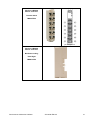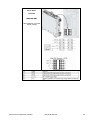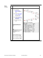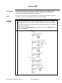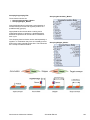
1
This document is based on European standards and is not valid for use in U.S.A. Compact / CANmotion / Motion Controller / LMC058 + Performance Packaging EIO0000000294 System User Guide MAY 2010 Contents Important Information ................................................................................................................3 Before You Begin..................................................................................................................4 Introduction ................................................................................................................................6 Abbreviations........................................................................................................................7 Glossary ................................................................................................................................8 Application Source Code .....................................................................................................9 Typical Applications...........................................................................................................10 System ......................................................................................................................................11 Architecture.........................................................................................................................11 Installation...........................................................................................................................15 Hardware ..........................................................................................................................................................20 Software ...........................................................................................................................................................55 Communication ...............................................................................................................................................56 Implementation ...................................................................................................................69 Communication ...............................................................................................................................................71 Controller .........................................................................................................................................................74 HMI..................................................................................................................................................................115 Devices...........................................................................................................................................................123 Altivar 312 .................................................................................................................................................124 Altivar 71 ...................................................................................................................................................128 Lexium 32A ...............................................................................................................................................131 Lexium SD3...............................................................................................................................................132 TeSysU ......................................................................................................................................................133 Advantys OTB ..........................................................................................................................................135 Appendix.................................................................................................................................140 The Packaging Application ..............................................................................................140 Application Specifics....................................................................................................................................142 Detailed Component List .................................................................................................154 Component Protection Classes.......................................................................................160 Environmental Characteristics ........................................................................................160 Component Features........................................................................................................161 Contact....................................................................................................................................168 Performance CANmotion LMC058 Schneider Electric 2 Important Information NOTICE Read these instructions carefully, and look at the equipment to become familiar with the device before trying to install, operate, or maintain it. The following special messages may appear throughout this documentation or on the equipment to warn of potential hazards or to call attention to information that clarifies or simplifies a procedure. The addition of this symbol to a Danger or Warning safety label indicates that an electrical hazard exists, which will result in personal injury if the instructions are not followed. This is the safety alert symbol. It is used to alert you to potential personal injury hazards. Obey all safety messages that follow this symbol to avoid possible injury or death. DANGER DANGER indicates an imminently hazardous situation, which, if not avoided, will result in death or serious injury. WARNING WARNING indicates a potentially hazardous situation, which, if not avoided, can result in death, serious injury, or equipment damage. CAUTION CAUTION indicates a potentially hazardous situation, which, if not avoided, can result in injury or equipment damage. PLEASE Electrical equipment should be installed, operated, serviced, and maintained only by qualified personnel. No responsibility is assumed by Schneider Electric for any NOTE consequences arising out of the use of this material. A qualified person is one who has skills and knowledge related to the construction and operation of electrical equipment and the installation, and has received safety training to recognize and avoid the hazards involved © 2008 Schneider Electric. All Rights Reserved. Performance CANmotion LMC058 Schneider Electric 3 Before You Begin Do not use this product on machinery lacking effective point-of-operation guarding. Lack of effective point-ofoperation guarding on a machine can result in serious injury to the operator of that machine. WARNING UNGUARDED MACHINERY CAN CAUSE SERIOUS INJURY Do not use this software and related automation products on equipment which does not have point-of-operation protection. Do not reach into machine during operation. Failure to follow these instructions can cause death, serious injury or equipment damage. This automation equipment and related software is used to control a variety of industrial processes. The type or model of automation equipment suitable for each application will vary depending on factors such as the control function required, degree of protection required, production methods, unusual conditions, government regulations, etc. In some applications, more than one processor may be required, as when backup redundancy is needed. Only the user can be aware of all the conditions and factors present during setup, operation and maintenance of the machine; therefore, only the user can determine the automation equipment and the related safeties and interlocks which can be properly used. When selecting automation and control equipment and related software for a particular application, the user should refer to the applicable local and national standards and regulations. A “National Safety Council’s” Accident Prevention Manual also provides much useful information. In some applications, such as packaging machinery, additional operator protection such as point-of-operation guarding must be provided. This is necessary if the operator’s hands and other parts of the body are free to enter the pinch points or other hazardous areas and serious injury can occur. Software products by itself cannot protect an operator from injury. For this reason the software cannot be substituted for or take the place of point-ofoperation protection. Ensure that appropriate safeties and mechanical/electrical interlocks for point-of-operation protection have been installed and are operational before placing the equipment into service. All mechanical/electrical interlocks and safeties for point-of-operation protection must be coordinated with the related automation equipment and software programming. NOTE: Coordination of safeties and mechanical/electrical interlocks for point-of-operation protection is outside the scope of this document. START UP AND TEST Before using electrical control and automation equipment for regular operation after installation, the system should be given a start up test by qualified personnel to verify correct operation of the equipment. It is important that arrangements for such a check be made and that enough time is allowed to perform complete and satisfactory testing. Performance CANmotion LMC058 Schneider Electric 4 CAUTION EQUIPMENT OPERATION HAZARD Verify that all installation and set up procedures have been completed. Before operational tests are performed, remove all blocks or other temporary holding means used for shipment from all component devices. Remove tools, meters and debris from equipment. Failure to follow these instructions can result in injury or equipment damage. Follow all start up tests recommended in the equipment documentation. Store all equipment documentation for future reference. Software testing must be done in both simulated and real environments. Verify that the completed system is free from all short circuits and grounds, except those grounds installed according to local regulations (according to the National Electrical Code in the U.S.A, for instance). If high-potential voltage testing is necessary, follow recommendations in equipment documentation to prevent accidental equipment damage. Before energizing equipment: • Remove tools, meters, and debris from equipment. • Close the equipment enclosure door. • Remove ground from incoming power lines. • Perform all start-up tests recommended by the manufacturer. OPERATION AND ADJUSTMENTS The following precautions are from NEMA Standards Publication ICS 7.1-1995 (English version prevails): Regardless of the care exercised in the design and manufacture of equipment or in the selection and rating of components, there are hazards that can be encountered if such equipment is improperly operated. It is sometimes possible to misadjust the equipment and thus produce unsatisfactory or unsafe operation. Always use the manufacturer’s instructions as a guide for functional adjustments. Personnel who have access to these adjustments should be familiar with the equipment manufacturer’s instructions and the machinery used with the electrical equipment. Only those operational adjustments actually required by the operator should be accessible to the operator. Access to other controls should be restricted to prevent unauthorized changes in operating characteristics. WARNING UNEXPECTED EQUIPMENT OPERATION Only use software tools approved by Schneider Electric for use with this equipment. Update your application program every time you change the physical hardware configuration. Failure to follow these instructions can cause death, serious injury or equipment damage. Performance CANmotion LMC058 Schneider Electric 5 Introduction Introduction This document is intended to provide a quick introduction to the described system. It is not intended to replace any specific product documentation, nor any of your own design documentation. On the contrary, it offers additional information to the product documentation, for installing, configuring and implementing the system. The architecture described in this document is not a specific product in the normal commercial sense. It describes an example of how Schneider Electric and third-party components may be integrated to fulfill an industrial application. A detailed functional description or the specification for a specific user application is not part of this document. Nevertheless, the document outlines some typical applications where the system might be implemented. The architecture described in this document has been fully tested in our laboratories using all the specific references you will find in the component list near the end of this document. Of course, your specific application requirements may be different and will require additional and/or different components. In this case, you will have to adapt the information provided in this document to your particular needs. To do so, you will need to consult the specific product documentation of the components that you are substituting in this architecture. Pay particular attention in conforming to any safety information, different electrical requirements and normative standards that would apply to your adaptation. It should be noted that there are some major components in the architecture described in this document that cannot be substituted without completely invalidating the architecture, descriptions, instructions, wiring diagrams and compatibility between the various software and hardware components specified herein. You must be aware of the consequences of component substitution in the architecture described in this document as substitutions may impair the compatibility and interoperability of software and hardware. This document describes a generic architecture based on Modicon LMC058 Motion controller S-Type and a packaging architecture based on Modicon LMC058 Motion controller S-Type. Performance CANmotion LMC058 Schneider Electric 6 Abbreviations Abbreviation AC CB CFC DI DO DC DFB EDS E-STOP FBD HMI I/O IL IP LD MFB PC POU PDO PS RMS RPM RTU RPDO SD SE SFC SDO ST TCP TPDO TVDA VSD WxHxD Performance CANmotion LMC058 Signification Alternating Current Circuit Breaker Continuous Function Chart – a programming language based on function chart Digital Input Digital Output Direct Current Derived Function Blocks Electronic Data Sheet Emergency Stop Function Block Diagram – an IEC-61131 programming language Human Machine Interface Input/Output Instruction List - a textual IEC-61131 programming language Internet Protocol Ladder Diagram – a graphic IEC-61131 programming language PLCopen Motion Function Block Personal Computer Programmable Object Unit, Program Section in SoMachine Process Data Object (CANopen) Power Supply Root Mean Square Revolution Per Minute Remote Terminal Unit Receive Process Data Object (CANopen) Stepper motor Drive Schneider Electric Sequential Function Chart – an IEC-61131 programming language Service Data Object Structured Text – an IEC-61131 programming language Transmission Control Protocol Transmit Process Data Object (CANopen) Tested, Validated and Documented Architecture Variable Speed Drive Dimensions : Width, Height and Depth Schneider Electric 7 Glossary Expression Advantys Altivar (ATV) CANopen CANmotion ConneXium Harmony ILA, ILE Lexium (LXM) Magelis Modicon LMC058 Motion controller OsiSense Phaseo PLCopen Preventa SD3 SoMachine TeSys Vijeo Designer Performance CANmotion LMC058 Signification SE product name for a family of I/O modules SE product name for a family of VSDs Name for a communications machine bus system Name for a communications motion bus system SE product name for a Family of Transparent Factory devices SE product name for a family of switches and indicators SE product name for a integrated drive Lexium SE product name for a family of servo drives SE product name for a family of HMI-Devices SE product name for a motion controller SE product name for a family of sensors SE product name for a family of power supplies An international standard for industrial controller programming. SE product name for a family of safety devices SE product name for Lexium stepper motor drives SD3 SE product name for an integrated software tool SE product name for a family of motor protection devices and load contactors An SE software product for programming Magelis HMI devices Schneider Electric 8 Application Source Code Introduction Examples of the source code and wiring diagrams used to attain the system function as described in this document can be downloaded from our website (registration is required, please contact your Schneider Electric Application Design Expert). The example source code is in the form of configuration, application and import files. Use the appropriate software tool to either open or import the files. Extension CSV DOC DWG EDS PDF PROJECT VDZ Z13 Performance CANmotion LMC058 File Type Comma Separated Values, Spreadsheet Document file Project file Electronic Data Sheet – Device Definition Portable Document Format - document Project file Project file Project archive file Schneider Electric Software Tool Required MS Excel Microsoft Word AutoCAD Industrial standard Adobe Acrobat SoMachine Vijeo Designer EPLAN 9 Typical Applications Introduction Here you will find a list of the typical applications and market segments, where this system or subsystem can be applied: Packaging Filling & closing machines Vertical bagging machines Boxing machines Carton closing / erecting machines Shrink wrapping machines Labeling machines Horizontal bagging machines Stretch wrapping machines Textile Opening and closing machines Circular knitting machines Plucker machines Blending machines Carding machines Drawing frame machines Combing machines Ring Spinning machines Scouring Bleaching machines Jigger machines Shrink wrapping machines Beaming warping machines Sizing machines Performance CANmotion LMC058 Schneider Electric 10 System Introduction The system chapter describes the architecture, the dimensions, the quantities and different types of components used within this system. Architecture General The controller in this application is a Modicon LMC058 Motion controller. The user controls the application using the Magelis HMI device. The Altivar variable speed drives, Lexium integrated drives and TeSysU motor starter connected to the controller via a CANopen fieldbus. The Lexium servo drives and Lexium stepper drives connected to the controller via a CANmotion bus. The example application includes two functional safety options according to EN ISO 13849-1 standards: an Emergency Stop function supervised by a Preventa safety module (see the appropriate hardware manual), plus a second Preventa safety module to evaluate protective door sensors Layout 1. Compact NSX100F main switch 2. Phaseo power supply ABL8 3. Modicon LMC058 Motion controller 4. Magelis XBTGT HMI 5. Lexium SD328 stepper drive 6. Lexium stepper motor BRS 7. Lexium 32 servo drive 8. Lexium servo motor BSH 9. Lexium servo motor BMH 10. Altivar 312 variable speed drive 11. Altivar 71 variable speed drive + encoder card 12. Absolute encoder XCC 13. Lexium integrated drive ILA 14. Lexium integrated drive ILE 15. CANopen encoder XCC Performance CANmotion LMC058 Schneider Electric 16. Harmony E-stop enclosure XALK 17. Preventa Safety module XPS 18. ConneXium Ethernet switch 19. Harmony tower light XVBC 20. Harmony push buttons enclosure XALD 21. TeSys motor protection GV2L 22. TeSysD contactor LC1D 23. Crouzet solid state relay (4x) 24. Heating element (4x) 25. Thermocouple Pt100 (4x) 26. Preventa safety switch XCS 27. AC-motor 28. TeSysU motor starter with CANopen module 29. Advantys OTB I/O-island with extension module 30. Multi 9 circuit breaker 31. Slow blow fuse 11 Components Hardware: Compact NSX100F main switch Phaseo power supply ABL8 Modicon LMC058 Motion controller Magelis XBTGT HMI Lexium 32 servo drive with BSH/BMH servo motor Lexium SD3 stepper drive with BRS stepper motor Altivar 312 and Altivar 71 variable speed drive Lexium integrated drive ILA and ILE Advantys OTB island TeSysU motor starter OsiSense (Osicoder) encoder Harmony pushbuttons Preventa XPS safety module TeSys motor protection GV2L TeSysD contactors ConneXium Ethernet switch Software: SoMachine V2.0 IclA Easy Quantities of Components Degree of Protection For a complete and detailed list of components, the quantities required and the order numbers, please refer to the components list at the rear of this document. Not all the components in this configuration are designed to withstand the same environmental conditions. Some components may need additional protection, in the form of housings, depending on the environment in which you intend to use them. For environmental details of the individual components please refer to the list in the appendix of this document and the corresponding user manual. Performance CANmotion LMC058 Schneider Electric 12 Cabinet Technical Data Functional Safety Notice (EN ISO 13849-1 EN IEC 62061) Input Mains voltage Power requirement Cable size Cable connection 400 Vac ~ 11 kW 5 x 2.5 mm² (L1, L2, L3, N, PE) 3 phase + Neutral + Ground Neutral is needed for 230 Vac (Phase and Neutral) Output Motor power ratings o 2 servo motors (BMH type with brake) controlled by LXM32 (continuous output current : 6 A RMS at 6000 RPM) o 2 servo motors (BSH type with brake) controlled by LXM32 (continuous output current : 6 A RMS at 6000 RPM) o 2 stepper motors (BRS type without brake) controlled by SD3 (max. nominal motor current: 2.5 A) o 1 integrated drives (brushless AC synchronous servo motor) controlled by ILA (max. continuous current input: 5 A) o 1 integrated drives (electronically commutated motor) controlled by ILE (max. continuous current input: 5 A) o 2 asynchronous motors controlled by ATV71 (0.75 kW) o 2 asynchronous motors controlled by ATV312 (0.75 kW) o 4 asynchronous motors controlled by ATV312 (0.37 kW) o 2 asynchronous motors controlled by ATV312 (0.75 kW) o 1 asynchronous motors controlled by TeSysU (1.5 kW) The standard and level of functional safety you apply to your application is determined by your system design and the overall extent to which your system may be a hazard to people and machinery. As there are no moving mechanical parts in this application example, category 1 (according to EN ISO 13849-1) has been selected as an optional safety level. Whether or not this functional safety category should be applied to your system should be ascertained with a proper risk analysis. This document is not comprehensive for any systems using the given architecture and does not absolve users of their duty to uphold the functional safety requirements with respect to the equipment used in their systems or of compliance with either national or international safety laws and regulations Emergency Stop Emergency Stop/Emergency Disconnection function Safety Function Door guarding This function for stopping in an emergency is a protective measure which compliments the safety functions for the safeguarding of hazardous zones according to prEN ISO 12100-2. up to Performance Level (PL) = b, Category 1, Safety Integrity Level (SIL) = 1 Performance CANmotion LMC058 Schneider Electric 13 Dimensions The dimensions of the individual devices used; controller, drives, power supply, etc. require a main cabinet size of at least 1200 x 1800 x 600 mm (WxHxD) and a remote cabinets with the size of 600 x 800 x 400 mm (WxHxD). The HMI display, illuminated indicators such as “SYSTEM ON“, “SYSTEM OFF“ or “ACKNOWLEDGE EMERGENCY STOP“ as well as the Emergency Stop switch itself, can be built into the door of the cabinet. Performance CANmotion LMC058 Schneider Electric 14 Installation Introduction This chapter describes the steps necessary to set up the hardware and configure the software required to fulfill the described function of the application. Assembly Main cabinet front Performance CANmotion LMC058 Schneider Electric 15 Remote cabinet front Performance CANmotion LMC058 Schneider Electric 16 Remote cabinet interior Performance CANmotion LMC058 Schneider Electric 17 Field devices and motors of main cabinet Performance CANmotion LMC058 Schneider Electric 18 Notes The components designed for installation in a cabinet, i.e. the controller, safety modules, circuit breakers, contactors, motor circuit breakers, power supply, TeSysU motor starter and Adantys OTB I/O modules can be mounted on a 35 mm DIN rail. The Magelis XBTGT HMI is mounted on the cabinet’s door. Main switch, solid state relay, Lexium 32A servo drives, Lexium SD3 stepper drives and Altivar variable speed drives are screwed directly onto the mounting plate. Alternatively the Altivar 312 and Lexium SD3 can be mounted on a DIN rail, if an adapter is used. The ILA and ILE integrated drives Lexium and the OsiSense (Osicoder) CANopen encoder are installed in the field. The Emergency Stop button, the door guard switches and the pushbutton housing for the display and acknowledgement indicators are designed for on-wall mounting in the field. All switches (except the door guard switch) can also be installed directly in a control cabinet (e.g., in a cabinet door) without special housings. There are two options for installing XB5 pushbuttons or indicator lamps: These pushbuttons or switches can be installed either in a 22 mm hole, e.g., drilled into the front door of the control cabinet, or in an XALD-type housing suitable for up to 5 pushbuttons or indicator lamps. The XALD pushbutton housing is designed for backplane assembly or direct wall mounting 400 Vac 3-phase wiring for the main circuit breaker, drives, stepper drives, motor starter and motors. 230 Vac 1-phase wiring between the main circuit breaker and Lexium drives. 230 Vac 1-phase wiring between the main circuit breaker and primary side of the 24 Vdc power supply. 24 Vdc wiring for control circuits and the controller power supply, I/O modules, HMI and integrated drives Lexium. The individual components must be interconnected in accordance with the detailed circuit diagram in order to ensure that they function correctly. CANopen cables are installed for the communications link between the controller and the, Lexium 32A, Lexium SD3, Altivar 71, Altivar 312, TeSysU, ILA & ILE integrated Lexium dives, OsiSense (Osicoder) and Advantys OTB I/O modules. Ethernet cables are installed for the communications link between the controller and the HMI. Performance CANmotion LMC058 Schneider Electric 19 Hardware General General description of the hardware. Mains Switch Compact NSX100F LV429003 36 kA 380/415 Vac Mains Switch Compact NSX100F LV429035 Trip unit TM32D Thermal-magnetic 32 A Ir - Thermal protection Im - Magnetic protection Mains Switch Compact NSX100F Rotary handle LV429340 Terminal shield LV429515 Rotary handle with red handle on yellow front Terminal shield short Power supply Phaseo ABL8RPS24100 24 Vdc, 10 A Performance CANmotion LMC058 Schneider Electric 20 Power supply Phaseo ABL8RPS24050 24 Vdc, 5 A Harmony Emergency Stop switch (trigger action) XALK178G Safety Module Preventa XPSAC5121 Performance CANmotion LMC058 Schneider Electric 21 Safety Module Preventa XPSAV11113Z002 Safety Module Preventa XPSECP5131 Expansion Module Performance CANmotion LMC058 Schneider Electric 22 Motor Circuit Breaker GV2L08 and GV2L14 with auxiliary contact GVAE11 GVAE11 Contactor TeSysD LC1D18BL Performance CANmotion LMC058 Schneider Electric 23 Modicon LMC058 Motion Controller LMC058LF424S0 Performance CANmotion LMC058 1. 2. 3. 4. 5. 6. 7. 8. 9. 10. 11. Status LEDs IF slots (not used in this architecture) Power supply Internal I/O area RS485 port Ethernet port Mini BUSB port USB A port Encoder connector CANopen and CANmotion ports Battery area Schneider Electric 24 Modicon LMC058 Motion Controller embedded power supply 1. Internal electronics 2. 24 Vdc I/O power segment integrated into the bus bases 3. PS1/PS2: External isolated power supply 24 Vdc limited to 200 VA for UL508 conformance, or limited to 150 VA for CSA 22.2, N° 142 conformance 4. External fuse type T slow-blow 3 A 250 V 5. External fuse type T slow-blow 1 A 250 V 6. External fuse type T slow-blow 6.3 A 250 V Performance CANmotion LMC058 Schneider Electric 25 Modicon LMC058 Motion Controller embedded fast I/O’s 1. Internal electronics 2. 24 Vdc I/O power segment integrated into the bus bases 3. 24 Vdc Embedded expert modules power by external connection Performance CANmotion LMC058 Schneider Electric 26 Modicon LMC058 Motion Controller embedded 12 Digital Inputs 1. Internal electronics 2. 24 Vdc I/O power segment integrated into the bus bases 3. 24 Vdc I/O power segment by external connection 4. 2-wire sensor Performance CANmotion LMC058 Schneider Electric 27 Modicon LMC058 Motion Controller embedded 12 Digital Outputs 1. Internal electronics 2. 24 Vdc I/O power segment integrated into the bus bases 3. Inductive load protection 4. 2-wire load 5. 0 Vdc I/O power segment by external connection Performance CANmotion LMC058 Schneider Electric 28 Modicon LMC058 Motion Controller embedded 4 Analog Inputs 1. Internal electronics 2. 24 Vdc I/O power segment integrated into the bus bases I Current U Voltage Modicon LMC058 Motion Controller Expansion module elements Performance CANmotion LMC058 Schneider Electric 29 Modicon LMC058 Motion Controller Bus base for electronic module TM5ACBM11 and for additional power supply TM5ACBM01R left side isolated Modicon LMC058 Motion Controller Electronic module Performance CANmotion LMC058 Schneider Electric 30 Modicon LMC058 Motion Controller Terminal block TM5ACTB12 pin assignment Modicon LMC058 Motion Controller Bus Base Locking Plate Right TM5ACLPR1 Performance CANmotion LMC058 Schneider Electric 31 Modicon LMC058 Motion Controller Expansion module TM5SPS2F power supply 1. Internal electronics 2. 24 Vdc I/O power segment integrated into the bus bases 3. Integrated fuse type T slow-blow 6.3 A 250 V exchangeable 4. 24 Vdc Main power 5. External fuse type T slow-blow 1 A 250 V Note: External isolated power supply 24 Vdc limited to 200 VA for UL508 conformance, or limited to 150 VA for CSA 22.2, N° 142 conformance. Modicon LMC058 Motion Controller Expansion module TM5SDI12D with 12 Digital Inputs Performance CANmotion LMC058 Schneider Electric 32 Modicon LMC058 Motion Controller Expansion module TM5SDO12T with 12 digital outputs Modicon LMC058 Motion Controller Expansion module TM5SAI2L with 2 Analog Inputs Performance CANmotion LMC058 Schneider Electric 33 Modicon LMC058 Motion Controller Expansion module TM5SAI4PH with 4 Analog Inputs (Pt100) Modicon LMC058 Motion Controller Expansion module TM5SAO4L with 4 Analog Outputs Performance CANmotion LMC058 Schneider Electric 34 Servo Drive Lexium32 LXM32AD18M2 1-phase 230 Vac, continuous output current 6 A RMS at 6000 RPM Servo Drive Lexium32 LXM32AD18M2 Embedded Human Machine Interface Performance CANmotion LMC058 Schneider Electric 35 Servo Drive Lexium32 LXM32AD18M2 Wiring diagram Power cable connection to motor (Length 5 m) Servo Drive Lexium32 LXM32AD18M2 Wiring diagram holding brake Servo Drive Lexium32 LXM32AD18M2 Parallel connection DC bus Performance CANmotion LMC058 Schneider Electric 36 Servo Drive Lexium32 LXM32AD18M2 Connecting the external braking resistor Servo Drive Lexium32 LXM32AD18M2 1-phase 115-240 Vac Wiring diagram power stage supply voltage for 1-phase device Performance CANmotion LMC058 Schneider Electric 37 Servo Drive Lexium32 LXM32AD18M2 Wiring diagram motor encoder Performance CANmotion LMC058 Schneider Electric 38 Servo Drive Lexium32 LXM32AD18M2 Wiring diagram controller supply voltage Performance CANmotion LMC058 Schneider Electric 39 Servo Drive Lexium32 LXM32AD18M2 Wiring diagram, digital inputs/outputs Servo Motor for Lexium32 BMH0702T02F2A with brake Performance CANmotion LMC058 Schneider Electric 40 Servo Motor for Lexium32 BSH0702P02F2A with brake Lexium SD3 Stepper motor drive SD328AU25S2 1-phase 115/230 Vac, 2.5 A Lexium SD3 Stepper motor drive SD328AU25S2 Power connection Performance CANmotion LMC058 Schneider Electric 41 Lexium SD3 Stepper motor drive SD328 AU25S2 Power cable connection to motor (Length 5 m) VW3S5101R50 Lexium SD3 Stepper motor drive SD328 AU25S2 Signal connections Performance CANmotion LMC058 Schneider Electric 42 Lexium SD3 Stepper motor drive SD328 AU25S2 Encoder connection via cable (Length 5 m) VW3S8101R50 Lexium SD3 Stepper motor drive SD328AU25S2 Wiring fieldbus control mode For the CANmotion or CANopen connection, the RJ45 connection (CN4) is used. Stepper Motors BRS3 3-phase for Lexium SD328 BRS397W261ACA With Incremental encoder (1000 pulses/revolution) Without holding brake Performance CANmotion LMC058 Schneider Electric 43 Variable Speed Drive Altivar 312 ATV312H037N4 and ATV312H075N4 3-phase 400 Vac, 0.37 kW and 0.75 kW Variable Speed Drive Altivar 312 ATV312H037N4 and ATV312H075N4 Power terminals Performance CANmotion LMC058 Schneider Electric 44 Variable Speed Drive Altivar 312 ATV312H037N4 and ATV312H075N4 Control terminals Variable Speed Drive Altivar 71 ATV71H075N4 3-phase 400 Vac, 0.75 kW Terminal connections including line supply and motor connections Performance CANmotion LMC058 Description of terminals: Schneider Electric 45 Encoder card for Altivar 71 VW3A3401 5 Vdc, RS422 Incremental Encoder for Altivar 71 XCC1510PS11X 5 Vdc, RS422 1024 pulses/revolution Performance CANmotion LMC058 Schneider Electric 46 Encoder cable for Altivar 71 XCCPM23121L5 Prewired M23 female connector with open end (length 5 m) Motor starter TeSysU LUB12BL Power base for two directions LU9B N11C Coil wiring kit Motor starter TeSysU LUCA05BL control unit Performance CANmotion LMC058 Schneider Electric 47 Motor starter TeSysU LULC08 CANopen communication module 1 2 24 Vdc power supply Terminal for coil wiring kit Motor starter TeSysU LU9MRL Coil wiring kit Integrated drive Lexium ILE with DC brushless motor ILE1F661PC1A1 Performance CANmotion LMC058 Schneider Electric 48 1. 2. 3. 4. 5. 6. 7. 8. 9. Brushless DC motor Electronics housing Insert for sealing (accessory) Insert with cable entry (accessory) I/O insert with industrial connector (accessory) Switches for settings Cover of electronics housing, must not be removed Cover of connector housing, to be removed for installation Cover with industrial connector for Vdc supply voltage and IN/OUT fieldbus connection (optional) 10. Electrical interfaces Performance CANmotion LMC058 Schneider Electric 49 Integrated drive Lexium ILA with servo motor ILA1F571PC2A 1. 2. 3. 4. 5. 6. 7. 8. 9. 10. 11. Synchronous AC servo motor Holding brake (optional) Encoder Electronics housing Insert for sealing (accessory) Insert with cable entry (accessory) I/O insert with industrial connector (accessory) Switches for settings Cover of electronics housing, must not be removed Cover of connector housing, to be removed for installation Cover with industrial connector for Vdc supply voltage and IN/OUT fieldbus connection (optional) 12. Electrical interfaces Performance CANmotion LMC058 Schneider Electric 50 Integrated drive Lexium Lexium ILA and Lexium ILE Industrial connector power supply and fieldbus connection VW3L30001R50 power connection cable, 5 m Integrated drive Lexium Lexium ILA and Lexium ILE Connection accessories 4x I/O, 1x STO in, 1x STO out VW3L40420 VW3L30010R50 VW3L50200 (2x) Performance CANmotion LMC058 Schneider Electric 51 Distributed I/O Advantys OTB OTB1C0DM9LP Base module 12 Digital Inputs 8 Digital Outputs Distributed I/O Advantys OTB TM2DDI8DT expansion I/O modules 8 Digital Inputs Distributed I/O Advantys OTB TM2DRA8RT expansion I/O modules 8 Digital Outputs Performance CANmotion LMC058 Schneider Electric 52 Harmony Tower light XVBC... Solid state relay SSRPCDS10A1 Input: Output: 3 … 32 Vdc 24 … 280 Vac 10 A Incremental Encoder for ATV71 type R (N): 5 V output driver, RS 422, 4.5…5.5 V. XCC1510PS11R Spring coupling XCCRAR1010 Performance CANmotion LMC058 Schneider Electric 53 CANopen multi-turn absolute encoder as standalone XCC3510PS84CB Performance CANmotion LMC058 Schneider Electric 54 Software General The main programming work lies in programming the Modicon LMC058 Motion controller, the configuration of the CANopen and CANmotion fieldbus and creating the screens for the HMI display. Programming the Modicon LMC058 Motion controller is done using SoMachine. Programming of the Magelis XBTGT 5330 HMI is done by using Vijeo Designer which is integrated into SoMachine. The configuration of the Advantys OTB Island is done using the Advantys Configuration Software. Configuration of the drives (ATV312, ATV71, SD328 and LXM32A) is done using the control panel on the drive. To use the software packages, your PC must have the appropriate Microsoft Windows operating system installed: Windows XP Professional The software tools have the following default install paths: SoMachine C:\Program Files\Schneider Electric\SoMachine Vijeo Designer (Installed with SoMachine) C:\Program Files\Schneider Electric\Vijeo Designer Advantys Configuration Software C:\Program Files\Schneider Electric\Advantys Performance CANmotion LMC058 Schneider Electric 55 Communication General The TVDA architecture includes three different communication networks. The CANopen fieldbus includes the Modicon LMC058 Motion controller as CANopen Master. The Altivar drives, Advantys OTB-Island, Integrated drive Lexium (ILA and ILE), TeSysU and OsiSense (Osicoder) are CANopen slave nodes. The CANopen transmission rate is 500 kBit/s. The CANmotion fieldbus includes the Modicon LMC058 Motion controller as Master. The Lexium 32 servo drives and Lexium SD3 stepper drives are slave nodes. The CANmotion transmission rate is 1 MBit/s. The Modicon LMC058 Motion controller and the Magelis HMI communicate using the SoMachine protocol based on Ethernet. Both devices are connected via an Ethernet switch. Also a PC can connect to this Ethernet switch for downloading to the HMI. The PC has to be connected to the controller over USB. The front panel is used to configure ATV312, ATV71, SD3 and LXM32A. Altivar 312 Modbus / CANopen port Node ID: 1..4 and 11+12 Note : In case of CANopen, the CANopen Tap TSXCANTDM4 is used to connect the VSD drive to the CANopen bus via RJ45 socket. Performance CANmotion LMC058 Schneider Electric 56 Altivar 71 Modbus / CANopen port Modbus/CANopen port Node ID: 5..6 Note : In case of CANopen, the CANopen Tap TSXCANTDM4 is used to connect the VSD drive to the CANopen bus via RJ45 socket. TeSysU CANopen communication module LULC08 The communication module is connected to the CANopen bus using cable TSXCANCADD1 TeSysU CANopen communication module LULC08 The baud rate is set to 500 kbps. Performance CANmotion LMC058 Schneider Electric 57 The following address is used: Node ID: 13 0 0 0 1 1 0 1 13 Advantys OTB CANopen OTB1CODM9LP 1. Network address (Node-ID x10) encoder wheel 2. Network address (Node-ID x1) encoder wheel 3. Transmission speed encoder wheel Node ID: 14 Baudrate 500 kBits/s Performance CANmotion LMC058 Schneider Electric 58 Advantys OTB CANopen Port OTB1C0DM9LP Integrated drive Lexium CANopen port Node ID: 21..22 Baudrate 500 kBits/s Performance CANmotion LMC058 Schneider Electric 59 OsiSense (Osicoder) CANopen multi-turn absolute encoder XCC3510PS84CB Node ID: 23 Baudrate (Bd) is set to 5 which is 500 kBits/s Performance CANmotion LMC058 Schneider Electric 60 Lexium SD3 CANmotion port Node ID: 1..2 Lexium 32A CANmotion port Node ID: 3..6 Pin Signal Meaning I/O 1. CAN_H CAN interface CAN level 2. CAN_L CAN interface CAN level 3. CAN_0V Reference potential CAN 4. nc not used 5. nc not used 6. nc not used 7. nc not used 8. nc not used - Performance CANmotion LMC058 Schneider Electric 61 CANopen TAP TSXCANTDM4 4 port CANopen junction box For the purpose of this application, the sliding switch should be set to OFF if it is not at the end of the CANopen line. CANopen TAP TSXCANTDM4 Note: When using devices which require a 24 Vdc power supply on CANopen line (such as TeSysU) the 24 Vdc power must be wired. Power supply: V+1 CG1 24 Vdc 0 Vdc Performance CANmotion LMC058 Schneider Electric 62 CANopen connector VW3CANKCDF90T, VW3CANKCDF90TP or VW3CANKCDF180T These connectors are used for the link to the CANopen node. VW3CANKCDF90T, VW3CANKCDF90TP VW3CANKCDF180T CANopen preassembled connection cable TCSCCN4F3M1T (length: 1.0 m) TSXCANCADD1 (length: 1.0 m) Used to connect the ATV312, ATV71 and TSXCANTDM4. Used to connect the controller, OTB, TeSysU and TSXCANTDM4. VW3CANCARR03 (length: 0.3 m) VW3CANCARR1 (length: 1.0 m) TCSCTN023F13M03 (length: 0.3 m) Used to connect the SD328. Used to connect the LXM32A. Performance CANmotion LMC058 Schneider Electric 63 CANopen cable TSXCANCx y The cable is available in various versions (x): A - Standard B - No Flame D - Heavy Duty and various lengths (y): 50 - for 50 m 100 - for 100 m, 300 - for 300 m. CANopen preassembled connection cable FTXCN32xx PIN 1 2 3 4 5 Used for the connection between the racks and the field devices. Performance CANmotion LMC058 Schneider Electric Signal Shield V+ GND CAN_H CAN_L Colour Red black White Blue 64 ConneXium Ethernet 5 port switch TCSESU053FN0 for the connection of Controller, HMI and PC Magelis HMI XBTGT5330 The Ethernet connection is used to communicate with the controller and the PC. ConneXium Ethernet cable 490NTW0000x Ethernet cable is used for the switch<->Controller, switch<->HMI and switch<->PC connection. Performance CANmotion LMC058 Schneider Electric 65 Controller LMC058 LMC058LF424S0 Performance CANmotion LMC058 1. CANmotion port 2. CANopen port 3. RS485 port 4. Ethernet port 5. Mini B USB port Schneider Electric 66 CANopen cabling component CANmotion cabling component Performance CANmotion LMC058 *1 – TSX CAN CADD1 *2 – TCS CCN4F3M1T *3 – FTX CN3250 *4 – FTX CN3210 *5 – FTX CNTL12 *6 – TSX CAN CD50 *7 – 1525704 (Phoenix Contact) *8 – 1525652 (Phoenix Contact) *1 – TCS CTN023F13M03 *2 – VW3 M3 805R010 *3 – VW3 CAN CARR 03 *4 – VW3 CAN CARR 1 *5 – TCS CAR01NM120 Schneider Electric 67 Ethernet cabling component Performance CANmotion LMC058 *1 – TCSESU053FN0 *2 – 490NTW0000x Schneider Electric (Ethernet switch) (Ethernet cable) 68 Implementation Introduction The implementation chapter describes all the steps necessary to initialize, to configure, to program and start-up the system to achieve the application functions as listed below. Function Start up and functional description 1. 2. 3. 4. 5. 6. Check if all motor circuit breakers and Multi9 circuit breakers are in ON position. Turn on the power using the main switch Acknowledge the Emergency Stop by pressing the acknowledge pushbutton Check safety guard(s) and acknowledge by pressing the acknowledge pushbutton Wait for the blue light to turn off Use Magelis XBTGT HMI to control the system. a. Use the “Bus”, “Alarm” and “Safety” screens to control error messaging and supervise the Emergency Stop. b. Use the “SD3”, “LXM32”, “ATV..”, “ILx” and “TeSysU” screen to control the different drives and motor starters. c. The “Mix” screen can be used to observe the I/O status of the OTB and the encoder values. Functional Layout Performance CANmotion LMC058 Schneider Electric 69 Course of Action , Performance CANmotion LMC058 Schneider Electric 70 Communication Introduction This chapter describes the data passed via the fieldbus and networks (e.g. CANopen or Ethernet) that are not bound directly with digital or analog hardware. The list contains: The device links Direction of data flow Symbolic name and Bus address of the device concerned. Device Links This application uses CANmotion and CANopen fieldbusses for field device communication. Additional the SoMachine protocol over Ethernet is used for HMI communication and connects: Magelis XBTGT HMI (IP 192.168.100.20) Modicon LMC058 (IP 192.168.100.30) Subnet Mask: 255.255.255.0 Performance CANmotion LMC058 Schneider Electric 71 CANopen connects the following devices: 1 Modicon LMC058 Motion controller on bus address 127 6 Altivar 312 variable speed drives, bus addresses 1..4 and 11..12 2 Altivar 71 variable speed drives, bus addresses 5..6 1 TeSysU motor starter, bus address 13 1 Advantys OTB I/O island, bus addresses 14 2 ILx Integrated drive Lexium, bus addresses 21..22 1 OsiSense (Osicoder) CANopen encoder, bus address 23 The baudrate used is 500 kBits/s CANmotion connects the following devices: 1 Modicon LMC058 Motion controller on bus address 127 2 Lexium SD328 stepper motor drives, bus addresses 1..2 4 Lexium 32A servo drives, bus addresses 3..6 The baudrate used is 1 MBits/s NOTE For the data exchange between the Controller and the Lexium 32A, Lexium SD328 stepper motor drive, Altivar 312, Altivar 71 and Integrated drive Lexium Ilx the PLCopen function blocks are used. It is not necessary to configure the data exchange manually. Performance CANmotion LMC058 Schneider Electric 72 Datalink OTB <> LMC058 Datalink TeSysU <> LMC058 LMC058 (CANopen-Master, #127) OTB (CANopen-Slave #14) Data Direction OTB -> LMC058 Name Designation i_usiOTBin1 First input byte (OTB 1CODM9LP) i_usiOTBin2 Second input byte (OTB 1CODM9LP) i_usiOTBin3 Third input byte (OTB TM2DDI8DT) Data Direction Controller -> LMC058 Name Designation q_usiOTBout1 First output byte (OTB 1CODM9LP) Second output byte (reserved) q_usiOTBout2 Third output byte (OTB TM2DDRA8RT) Controller (CANopen-Master, #127) TeSysU (CANopen-Slave #13) Data Direction TeSysU -> LMC058 Name Designation i_uiTeSysStat Status data of TeSysU Data Direction LMC058 -> TeSysU Name Designation q_uiTeSysCtrl q_uiTeSysCtrlCom Datalink Osicoder <> LMC058 Control data of TeSysU Control of comm module OsiSense (Osicoder) (CANopen-Slave LMC058 (CANopen-Master, #127) #23) Data Direction OsiSense (Osicoder) -> LMC058 Name Designation i_udiEncoder Value Actual position value Performance CANmotion LMC058 Schneider Electric 73 Controller Introduction The Controller chapter describes the steps required for the initialization and configuration and the source program required to fulfill the functions. Requirements SoMachine V2 is installed on your PC The Modicon LMC058 Motion controller is switched on and running The controller is connected to the HMI with the Ethernet cable 490NTW0000x (controller to HMI) The controller is connected to the PC via the USB cable TCSXCNAMUM3P Setting up the controller is done as follows: Create a new project Add the controller Add Expansion Modules Add the CANopen fieldbus Add CANopen devices Import the OTB EDS file ATV312 CANopen configuration ATV71 CANopen configuration OTB CANopen configuration TeSysU CANopen configuration OsiSense (Osicoder) CANopen configuration Integrated drive Lexium ILx CANopen configuration Add the CANmotion bus Add CANmotion Devices CANmotion device configuration Add Toolbox Library Add POU Task configuration Add Vijeo Designer HMI Ethernet settings Configure Controller ↔ HMI Data Exchange Communication Setting Controller ↔ PC Communication Setting HMI ↔ PC Save the Project Build Application Download the Controller and HMI project Login to the Controller Application overview Performance CANmotion LMC058 Schneider Electric 74 Create a new project 1 To create a new project select Create new machine → Start with empty project 2 In the Save Project As dialog enter a File name and press Save. Note: As default the project is saved under My Documents. 3 The SoMachine User Interface opens. 4 In the User Interface select the Program tab Performance CANmotion LMC058 Schneider Electric 75 Add a controller 5 The Program window appears 1 Right click on Performance_CANmotion_ LMC058. Select Add Device… in the pop up menu. 2 Select Schneider Electric as Vendor. Then select: Motion Controller LMC058LF424S0 as the controller device. Click on Add Device. Performance CANmotion LMC058 Schneider Electric 76 Add Expansion Modules 3 The Devices folder now displays the new controller. 1 To add an expansion module, right click on TM5_Manager and click on Add Device… Performance CANmotion LMC058 Schneider Electric 77 2 Select the expansion module and click on Add Device. For this project add the following cards: 1x TM5SPS2F 2x TM5SDI12D 1x TM5SDO12T 1x TM5SDI12D 1x TM5SAI2L 1x TM5SAO4L 1x TM5SAI4PH Once you have added all the cards Close the dialog. 3 The added expansion module can now be seen at the end of the device list. Performance CANmotion LMC058 Schneider Electric 78 Add the CANopen fieldbus 1 Right click on CAN0 and select: Add Device... 2 Select: CANopen Performance Click on Add Device. 3 Double click on CAN0 and select for Baudrate (bit/s) 500000 in the pull down menu. Performance CANmotion LMC058 Schneider Electric 79 Import the OTB EDS file 1 To use the extended OTB island (configured by Advantys Configuration Software) you have to import the OTB eds file. Select Tools -> Device Repository. 2 In the Device Repository select Install … 3 Select the OTB EDS file. In this project the OTB EDS file is named OTB_TVD_Perf_LMC058.eds Press Open Performance CANmotion LMC058 Schneider Electric 80 Add CANopen Devices 4 Press Close 1 Right click on the CANopen_Performance and select Add Device… in the pop-up menu. Performance CANmotion LMC058 Schneider Electric 81 2 Select the device that you wish to connect to the CANopen bus. In this project the following devices are connected to the CANopen bus: 4x Altivar 312 2x Altivar 71 2x Altivar 312 1x TeSysU_Sc_St 1x OTB_TVD_Perf_LMC058 1x Lexium ILA 1x Lexium ILE 1x OsiSense (Osicoder) Add each device by clicking on Add Device. Once you have added all devices click on Close. Performance CANmotion LMC058 Schneider Electric 82 Performance CANmotion LMC058 Schneider Electric 83 Performance CANmotion LMC058 Schneider Electric 84 3 The new devices are now listed in CANopen_Performance. To configure the devices, double click on the specific item. ATV312 CANopen configuration 1 Double click on the Altivar_312. Note: In this project PLCopen EDS files are used. For this reason all PDO settings remain at their defaults. Set the Node Id to 1 (Node ID for the Altivar 312 is 1…4 and 11 + 12). Performance CANmotion LMC058 Schneider Electric 85 2 To change the name of the CANopen device, click on the old name. Note: The name of the device is also the AXIS REF name for the PLCopen functions used in the application program Note: The following naming is used in our example project. ATV71 CANopen configuration 1 The configuration is done in the same way as the ATV312 configuration. The only difference is the CANopen (5…6) address. Performance CANmotion LMC058 Schneider Electric 86 OTB CANopen 1 Configuration 2 Double click on OTB_TVD_Perf_LMC058 in this project it is renamed to can14_OTB. Change the Node ID to 14 Check Enable Expert PDO Settings, Create all SDOs, Factory Settings and Enable Heartbeat Generation. Select 200 for the Heartbeat producer time. 3 In the CANopen I/O Mapping tab, the OTB inputs and outputs are mapped to variables. There are two ways of Mapping: 1.Mapping to an existing variable 2.Creating a new variable In this project create a new variable was chosen. This means SoMachine creates a global variable which can be used throughout the whole program. The names of the variables can be entered in the Variable field. Performance CANmotion LMC058 Schneider Electric 87 TeSysU CANopen configuration 1 To configure the TeSysU double click on can13_TeSysU 2 Change the Node ID to 13 3 In the CANopen I/O Mapping tab, the TeSysU inputs and outputs are mapped to variables. There are two ways of Mapping: 1.Mapping to an existing variable 2.Creating a new variable In this project create a new variable was chosen. This means SoMachine creates a global variable which can be used throughout the entire program. The names of the variables can be entered in the Variable field. OsiSense (Osicoder) CANopen configuration 1 To configure the OsiSense (Osicoder) double click on can23_Osicoder. Performance CANmotion LMC058 Schneider Electric 88 2 Change the Node ID to 23 and select the checkbox Enable Expert PDO Settings Integrated drive Lexium ILx CANopen configuration 3 Go to the PDO Mapping tab and select by double click the TxPDO1 4 Set the Event Time to a value greater 0. In this project it is 100 ms. If the value is 0, the OsiSense (Osicoder) will not send any data. 5 In the CANopen I/O Mapping tab, the position value of the OsiSense (Osicoder) is mapped to a variable. 1 To configure the Lexium ILx double click on can21_ILA. and for the second Lexium ILx double click on can22_ILE. Note: In this project Motion EDS files are used. For this reason all PDO settings remain at their defaults. 2 Set Node ID to 21. For the 2nd ILx set Node ID to 22. And checkmark EnableExpertPDOSettings. Performance CANmotion LMC058 Schneider Electric 89 3 Go to the Service Data Object tab and click New… 4 In the Select item from object directory dialog select 16#301C:16#00 | Settings1 :16#0D Settings.SignEnabl set Value to 0 and click OK NOTE: In our example application we set the Settings.SignEnabl to 0 because we use the modulo motion mode (endless movements). If your application requires the end of travel limits then set the Settings.SignEnabl to 1. Verify that your application doesn't require these signals before disabling them. Add the CANmotion bus 5 The new SDO is now in the Service Data Object tab. 1 Right click on CAN1 and select: Add Device... Performance CANmotion LMC058 Schneider Electric 90 2 Select: CANmotion Click on Add Device. 3 Double click on CAN1 and select for Baudrate (bit/s) 1000000 from the pull down menu. Performance CANmotion LMC058 Schneider Electric 91 4 Double click on CANmotion In the tab CANopen Manager the sync cycle period can be changed. Now it is set to 4ms = 4000 µs This is also the time base for the task configuration. 5 In the CANopen I/O Mapping tab the Bus cycle task is linked to Motion. Add CANmotion Devices 1 Right click on the CANmotion and select Add Device… in the pop-up menu. Performance CANmotion LMC058 Schneider Electric 92 2 Select the device they connected to the CANmotion bus. In this project: 2x Lexium SD3 4x Lexium32A Add each device by clicking on Add Device. Once you have added all devices click on Close. 3 The new devices are now listed under CANmotion. To configure the devices, double click on the specific item. Performance CANmotion LMC058 Schneider Electric 93 CANmotion device configuration 4 The automatically generated names can be changed by selecting the name. 1 Double click on the communication section of the first device motion01_SD3. Note: In this project SoftMotion EDS files are used. For this reason all PDO settings remain at their factory settings. Set the Node Id to 1 (Node ID for the SD3 is 1…2 and for LXM32 is 3…6). 2 The factory settings of the axis can be changed at the tab Service Data Objects. If one data is missing click on New.. . 3 Then select the needed item. In this case we select the Homing method. Change the value to 33 (index pulse neg. direction). Press OK to add this to the list. Performance CANmotion LMC058 Schneider Electric 94 4 Double click on motion section of the first device SM_01_SD3. Note: The name of the axis is also the AXIS REF name for the SoftMotion functions used in the application program. 5 The first tab of the axis SoftMotion Drive: Basic provides several boxes for the configuration of the basic settings for the inserted device. For more detail, please see the online help of SoMachine. 6 The SoftMotion Device: Scaling/Mapping tab provides the adjustment of the physical setting of the axis In the exemplary configuration the drive creating 217 = 131072 = 20000hex increments for one rotation. And the technical unit is set to 60. Now the speed can be given in RPM/min to the axis. Add Toolbox Library 1 To use the additional functions you need a special library. These can be inserted by double clicking on Library Manager. 2 In the Library Manager click on Add library… Performance CANmotion LMC058 Schneider Electric 95 3 In the Add library dialog on the Placeholder tab select: Placeholder name→ SE_Toolbox and as Default Library Util → Toolbox for the Toolbox lib. In each case, click on OK to add the library. Add a POU (example) 4 If you need to add more libraries repeat steps 1 to 3. 1 Right click on Application→ Add Object… 2 Select POU and enter a Name (for example OTB_Data). As Type select Program and as Implementation language select CFC. It is possible to select all the IEC languages and to generate functions and function blocks. Click on Open. 3 The new POU OTB_Data is now visible under Application. Double click on OTB_Data to open it. Performance CANmotion LMC058 Schneider Electric 96 4 The upper frame displays the declaration section. The lower frame is for programming. On the right side is the ToolBox window. Use drag and drop with the toolbox to place example templates in the programming section. 5 Once you have placed a template in the programming section click on the ???. 6 Start typing the name for a function or function block. When the first letters are typed a pop-up menu opens with hints for the name. In this example an UNPACK FB was chosen. The UNPACK FB converts bytes to bits. 7 To instantiate the FB click the ??? … 8 … and type the name (for example mcUNPACK). Now press Enter. The Auto Declare dialog opens. Here click on OK to create the instance. Note: If you wish to add a comment you can do this in the Comment box. Performance CANmotion LMC058 Schneider Electric 97 9 The new FB UNPACK is instantiated in the declaration section of the OTB_Data. 10 To connect a variable to an input place an input field from the ToolBox on the input side of the FB and connect the input box to the FB input by clicking on the red field and dragging it to the input of the FB. 11 Click the input field and press F8. The Input Assistant is displayed. Performance CANmotion LMC058 Schneider Electric 98 12 In the Input Assistant select Global Variables→ MyController→ CAN0→ CANopen_Performance→ IOConfig_Globals_Mapping and then the variable. In this project the variable is the first input byte of the OTB. Click on OK. 13 This image shows the FB with the connected input. 14 Output selection is similar to input definition, but here we create a new variable. Click the output field, type in the name of the variable and press Enter. In the Auto Declare dialog select the Scope, the Name and the Type. In this example VAR_GLOBAL is chosen as Scope. 15 When finished click on OK. The VAR_GLOBAL variables are located in the GVL folder. All variables located in this folder can be accessed throughout the entire Application. If the variables are located in the POU, they can only be accessed by the POU (local variables). Performance CANmotion LMC058 Schneider Electric 99 Task Configuration 1 Before you can start working with the new POU you have to add it to a task. Here, the POUs are added to the MAST task. To do this double click the MAST task and click on Add POU. Note: If a POU is not included in a TASK, or added in another POU, which is cyclically invoked, it will not be cyclically invoked. 2 Select in Categories Programs (Project) and select the POU in the Items list. Then click OK. Note: You have to add all POUs in the program. 3 Now the POU is in the MAST task. In the upper part of the MAST task configuration you can change the Type of the task. In this project it is Freewheeling. Performance CANmotion LMC058 Schneider Electric 100 4 To add a POU to the motion task double click the Motion and click on Add POU. Select the POU like in step 2. Note: This task is linked to the motion configuration. The time base, in this application is set to 4ms. See at “Add the CANmotion bus” and step 4. Add Vijeo Designer HMI 1 To add a Vijeo Designer HMI unit to the project right click on Performance_CANmotion _LMC058 and select Add Device… 2 In the Add Device select Schneider Electric as Vendor. Click on: Magelis HMI-> XBTGT5000 Series-> XBTGT5330. Click on Add Device. Performance CANmotion LMC058 Schneider Electric 101 3 The new XBTGT5330 is now listed in the configuration. Note: With this XBTGT5330, the Program Vijeo Designer opens and you can start programming. (See chapter HMI) Ethernet settings 1 To change the Ethernet settings double click Ethernet 2 Check the fixed IP Address box and set an IP Address (In this project 192.168.100.30) and a Subnet Mask (In this project 255.255.255.0) Note: The USB cable TCSXCNAMUM3P must be used for the initial project download. For subsequent downloads, the Ethernet connection can be used. Performance CANmotion LMC058 Schneider Electric 102 Configure Controller <-> HMI Data Exchange 1 In the browser right click on: Application → Add Object… 2 Select Symbol configuration in the Add Object dialog. Click on Open. 3 Click on Refresh in the now open Symbol configuration. The left window shows the Available Items. The right window shows the Selected Variables which can be used in the HMI. 4 All Variables created in the user program are shown in the Available variables list. In this project all variables are global variables and are located in the GVL folder. To export variables to the HMI, select GVL and click on > . Performance CANmotion LMC058 Schneider Electric 103 5 In addition for structured variables you need to select corresponding data types. Go to Data Types and select one by one the items and click on >. 6 Communication 1 Setting Controller <-> PC 2 To export the selected variables to Vijeo Designer right click on HMI Application and select Export Symbols to VijeoDesigner. To configure the communication gateway double click on MyController. On the Communication Settings tab click on: Add gateway... 3 Keep the default settings and click on OK. Performance CANmotion LMC058 Schneider Electric 104 4 Select Gateway-1 and click on Scan network. 5 When the scan is finished, the devices are listed under the Gateway-1. Select the appropriate controller and click Set active path. 6 A warning pop-up window opens. Read the warning and once you have fulfilled the instruction, continue. 7 The used controller is now marked as active. Performance CANmotion LMC058 Schneider Electric 105 8 NOTE: Every LMC058 has a unique MAC address that is a part of the default name (in this case: @0080F44000D8). If you would like to change the default name of your controller: click on Edit… In the displayed pop-up window go to the Device Name field and enter the new unique name for your controller. In our example we keep the factory setting name. Performance CANmotion LMC058 Schneider Electric 106 Communication 1 Setting HMI <-> PC To configure the communication gateway double click on XBTGT5330. 2 On the Communication Settings tab, click on Add gateway. 3 Retain the factory settings and click OK. 4 Select Gateway-1 and click Scan network. 5 When the scan is finished, the devices are listed under the Gateway-1. Select the appropriate HMI and click on Set active path. Performance CANmotion LMC058 Schneider Electric 107 6 A Warning pop-up window opens. Read the warning and once you have fulfilled the instruction, continue. Save the Project 7 The selected HMI is now marked as active. 1 To save the project and change the name click File->Save Project As… 2 Enter the File name and click on Save. Note: As default the project is saved under My Documents. Performance CANmotion LMC058 Schneider Electric 108 Build Application 1 To build the application click on Build → Build ‘Application [MyController: PLC Logic]’. Note: If you wish to build the entire project (HMI and Controller) click Build All 2 After the build you are notified in the Messages field as to whether the build was successful or not. If the build was not successful there will be a list in the Messages field. Performance CANmotion LMC058 Schneider Electric 109 Download the Controller and HMI project 1 NOTE: For the initial download, the Magelis HMI requires the latest version of the runtime kernel and the Controller address. This is accomplished by using Vijeo Designer for the initial download This first download is described in the following steps. If this is not the initial Magelis HMI download go direct to step 7. 2 In Vijeo Designer, under the Property Inspector select Download via Ethernet. Note: The PC should be connected with the HMI via the Ethernet switch TCSESU053FN0. The IP address of the target machine can be set by using the Offline Configuration Menu of the XBTGT HMI. For more detail, please see the online help of Vijeo Designer. Performance CANmotion LMC058 Schneider Electric 110 3 Select Build → Download All. 4 The VDPLoad dialog box shows; Runtime versions do not match. Start the download of the new version by clicking on Yes. 5 The actual state of the download is displayed. 6 After the download, change the Download option back to SoMachine. Performance CANmotion LMC058 Schneider Electric 111 7 To download the project to the controller and the HMI click Online → Multiple Download … 8 Check the boxes for the controller MyController, the HMI XBTGT5330 and select Always perform a full download. Click on OK. 9 Click Yes if you want to do so. 10 The results of the download to the PLC and the HMI are displayed in the Multiple Download – Result window. Click on Close to close the results window. Performance CANmotion LMC058 Schneider Electric 112 Login to Controller 1 To login to the controller select Online → Login 2 To start the new Application select Online → Start 3 If you want to start the application click on Yes. 4 If everything is running properly the devices and folders are marked in green otherwise they will be marked in red. Performance CANmotion LMC058 Schneider Electric 113 Application overview 1 The picture on the right shows the structure of the Application. Performance CANmotion LMC058 Schneider Electric 114 HMI Introduction This application uses a Magelis XBTGT5330 HMI. This HMI device communicates via the SoMachine protocol over Ethernet with the controller. The HMI is programmed using the software tool Vijeo Designer (delivered with SoMachine), described briefly in the following pages. For the connection between the controller and the HMI use the cable Ethernet cable 490NTW00005. NOTE: The Vijeo Designer Tool is opened and closed via SoMachine software. For more information see chapter Controller: Add Vijeo Designer HMI Setting up the HMI is done as follows: Main Window Communication settings Create a switch Create a numeric display Example screens Performance CANmotion LMC058 Schneider Electric 115 Main Window 1 After double click on the XBTGT5330 in SoMachine, Vijeo Designer opens the HMI main window. Performance CANmotion LMC058 Schneider Electric 116 Communication settings 1 To set the communication parameters, in the Navigator select IO Manager → SoMachineNetwork01 → SOM_MyController 2 In the dialog set the PLC Equipment Address. You will find this address in SoMachine… 3 … by double clicking the MyController. 4 In the Communication tab select the controller and click on Edit. 5 The Equipment Address of the controller is displayed under Device Name. Performance CANmotion LMC058 Schneider Electric 117 Create a switch 1 Select the Switch icon in the Tool bar. 2 Select the position where you wish to place the button by opening a rectangle on the display and pressing Enter. 3 In the Switch Settings dialog, select the variable that should be linked (use the bulb icon to do this) to the button. Performance CANmotion LMC058 Schneider Electric 118 4 Click on the bulb icon (as indicated in the image above) to open the Variables List dialog. Go to the SoMachine tab, select the required variable and click OK. 5 In the Switch Settings dialog go to the Label tab. Here select Label Type: Static and enter a name for the button, e.g. enable. Once you have entered your settings click on OK. 6 The display now shows the new button. Performance CANmotion LMC058 Schneider Electric 119 Create a Numeric Display 1 Click on the Numeric Display icon in the tool bar. 2 Select the spot where you want to position the display by opening the rectangle and pressing Enter. 3 In the Numeric Display Settings dialog go to the General tab. In Display Digits you can set the maximum number of the digits to be displayed for both integral and fractional part of the value. To link a Variable to the display click on the bulb icon to browse for a variable. Press OK. Example screens 4 The display shows the new numeric display. 1 The Bus page shows the CANopen status for all devices. Performance CANmotion LMC058 Schneider Electric 120 2 The “Safety” page shows the status of the emergency stop relay. 3 Via the SD3 page it is possible to control and observe the Lexium SD3 stepper drives. 4 Via the two LXM 1..2 and LXM 3..4 pages it is possible to control and observe the four Lexium 32A drives. LXM 1..2: LXM32A node 3+4 LXM 3..4: LXM32A node 5+6 5 Via the two ATV 1..4 and ATV 5..8 pages it is possible to control and observe the eight Altivar drives. ATV 1..4: ATV312 node 1..4 ATV 5..8: ATV71 node 5+6 ATV312 node 11+12 Performance CANmotion LMC058 Schneider Electric 121 6 On the ILx page it is possible to control and observe the two Lexium Integrated drives ILA and ILE. 7 On the TeSysU page it is possible to control and observe the TeSysU motor starters. 8 The Mix page shows the status of the input and output bits of the Advantys OTB island, the CANopen OsiSense (Osicoder) and the local encoder. 9 The Home page of the HMI shows a picture of the main rack. Performance CANmotion LMC058 Schneider Electric 122 Devices Introduction This chapter describes the steps required to initialize and configure the different devices required to attain the described system function. General Altivar 312, Altivar 71, Lexium SD3 and Lexium 32A drives are configured by using the local control panel. The extended Advantys OTB IO island is configured by using the Advantys Configuration Software The Advantys OTB CANopen addresses & baudrate are configured by using the onboard rotary switches. Note It is recommended that the controller is in stop mode before parameterizing the drives. Performance CANmotion LMC058 Schneider Electric 123 Altivar 312 Introduction The ATV312 parameters can be entered or modified via the local control panel on the front of the device. Note If this is not a new drive it is recommended to return to the factory settings. If you need instructions on how to do this, please read the drive documentation. Jog dial that is a part of the local control panel and can be used for navigation by turning it clockwise or counter-clockwise. Pressing the jog dial enables the user to make a selection or confirm information. Control panel 1 The CANopen-Address and Baudrate can be input using the buttons and the jog dial on the control panel of the Altivar. Performance CANmotion LMC058 Schneider Electric 124 CANopen settings 1 Using the buttons on the front panel, select the sub-menu Communication. 2 In the Communication (COM) sub-menu input the CANopen address in the parameter AdC0. In the example application the addresses for the six drives are 1 to 4, 11 & 12. 3 Also in the Communication (COM) sub-menu, in the parameter BdC0, set the Baudrate to 500.0 (kBits). 4 For the ATV312 to operate with the new address or Baudrate, a power cycle (on, off, on) is required. Performance CANmotion LMC058 Schneider Electric 125 Changing the Access Level LAC 1 To set the parameters for the brake function a higher access level (L3) is required. 2 To go to expert mode L3: Select CtL [COMMAND] and press enter Select LAC [ACCESS LEVEL] and press enter L1 (Level 1) is displayed Select L3 (Level 3) and press enter for 2 seconds to set the new level. Return to the LAC with ESC. Return to the CtL with ESC. Performance CANmotion LMC058 Schneider Electric 126 Brake settings 1 The r2 relay output is used for brake control. 2 To assign the r2 relay output : Select FUn[APPLICATION FUNCT.] and press enter Select bLC- [BRAKE LOGIC CONTROL] and press enter Select bLC [BRAKE ASSIGNMENT] and press enter Select r2 and press enter. Set the parameters to the values shown here on the right. Note: These parameters are for the test machine only. They are NOT VALID for every machine. After all parameters are set return to the bLC with ESC. Return to the bLC- with ESC. Return to the FUn with ESC. Performance CANmotion LMC058 Schneider Electric 127 Altivar 71 Introduction The ATV71 parameters can be entered or modified using the graphic keypad panel. Note If this is not a new drive it is recommended to return to the factory settings. If you need instructions on how to do this, please refer to the drive documentation. CANopen settings 1 The CANopen address and Baudrate can be input using the jog dial on the front panel of the Altivar. 2 To set the CANopen address and the Baudrate go to 1 DRIVE MENU and press Enter. 3 Go to 1.9 COMMUNICATION and press Enter. 4 Go to CANopen and press Enter. 5 Set the CANopen address to 5 for the first one. For the other drives it is 6. Set the CANopen bit rate to 500 kbps. Performance CANmotion LMC058 Schneider Electric 128 6 After changing the configuration it is necessary to power cycle the drive. Note: For high power drives (more than 90 kW) it is recommended to do an automatic reboot with the graphic keypad panel (refer to drive user’s manual for details) Brake settings 1 To change the brake settings go to: 1 DRIVE MENU and press Enter. 2 Go to 1.7 APPLICATION FUNCT. and press Enter. 3 Go to BRAKE LOGIC CONTROL and press Enter. Performance CANmotion LMC058 Schneider Electric 129 4 Set the parameters to the values shown here on the right. Note: These parameters are for the test machine only. They are NOT VALID for every machine. Performance CANmotion LMC058 Schneider Electric 130 Lexium 32A Introduction The LXM32A parameters can be entered or modified using the local control panel on the front of the device. Note If this is not a new drive it is recommended to return to the factory settings. If you need instructions on how to do this, please refer to the drive documentation. CANopen settings 1 If the drive is being started for the first time, the FSu (First Setup) is invoked. Only the CANopen address (CoAd) and the baudrate (Cobd) are initially needed. If the drive has never been started before, follow the steps below to change the address or the baudrate. In this project the CANmotion addresses for the drives are 3…6. The Baudrate for the drives is 1000 kBaud. Performance CANmotion LMC058 Schneider Electric 131 Lexium SD3 Introduction The SD328 parameters can be entered or modified via the local control panel on the front of the device. Before you could start the drive configuration with SoMachine it is mandatory to set a CANopen address and a Baudrate. Note If this is not a new drive it is recommended to return to the factory settings. If you need instructions on how to do this, please read the drive documentation. CANopen settings 1 If the drive is started for the first time, the FSu (First Setup) starts. Then CANopen (CAno) must be set and the CANopen address (CoAd) and the baudrate (Cobd). If the drive is not started for the first time, follow the steps underneath to change the address or the baudrate. In this project the CANopen address for the drives are 1 + 2. The Baudrate for the drives is 1000 kBaud. 2 Performance CANmotion LMC058 Schneider Electric 132 TeSysU Introduction This chapter concerns the TeSysU motor starter components used in this system. They can be adapted according to the application (motor output, reversing or non-reversing). Basically, the TeSysU motor control unit comprises of: - Power base Control unit Communication module Coil wiring kit Optional: reversing block, Is limiter/isolation block and other modules The following points should be taken into account when selecting components: A 24 Vdc LU2B xx BL control unit must be used. Verify that it has the BL extension. There are different versions of the coil wiring kit, which depends on the power base. LU9BN11C should be used if the power base has one direction of rotation (LU2Bxx) and LU9MRL should be used if the power base has two directions of rotation (LU2Bxx). TeSysU 1 TeSysU Power base LU2B12BL Control unit LUCA05BL Communication module for CANopen LULC08 (1) Coil wiring kit LU9MRL (2) 2 TeSysU CANopen communication module LULC08 The communication module is connected to the CANopen bus using cable. TSXCANCADD1 Performance CANmotion LMC058 Schneider Electric 133 3 TeSysU CANopen communication module LULC08 The baud rate is set to 500 kbps. 4 The following address is used: Bus address 13: 0 5 0 0 1 1 0 1 13 NOTE: TeSysU needs 24 Vdc on CANopen cable to operate. See the chapter: Communication: CANopen TAP: TSXCANTDM4 wiring. Performance CANmotion LMC058 Schneider Electric 134 Advantys OTB General The extended OTB EDS (electronic data sheet) file is generated by using the Advantys Configuration Software. This section describes how to generate an EDS file, that can be imported into SoMachine Device Repository (see chapter Controller). Note If the user is using only the basic OTB module; the OTB1CODM9LP device can be used that is already installed in SoMachine Device Repository. Advantys OTB Configuration 1 On start-up of Advantys Software select your Language and click on OK. 2 Select: File -> New Workspace… 3 Type in the Workspace File Name and the Island File Name. Click on OK. Performance CANmotion LMC058 Schneider Electric 135 4 The Advantys window opens with empty configuration workspace. On the right side of the workspace is the Catalog browser. Select the appropriate modules. 1x OTB1CODM9LP 1x TM2DDI8DT 1x TM2DRA8RT 5 The image on the right shows the configured rack. Performance CANmotion LMC058 Schneider Electric 136 6 Click on the I/O Image Overview icon 7 The I/O Image Overview opens in the tab TxPDO’s. The digital Inputs are located to the TxPDO Mapping 1 8 Select the PDO Configuration tab Open the Transmit PDO Parameter 1 for the 1st module. There the factory settings can be changed. Inhibit Time: 100 Event Timer: 100. Close the window with OK Note: With the Inhibit Time=0 and Event Timer=0 the analog values are not transmitted via the CANopen. Performance CANmotion LMC058 Schneider Electric 137 9 To store the configuration press Save Workspace and OK 10 To generate the EDS File select File -> Export OTB_TVD_Perf_LMC058 11 Enter the Filename and select EDS as Export Format. Continue the export with OK. Performance CANmotion LMC058 Schneider Electric 138 12 Select Network Configuration SyCon or CoDeSys and click OK. 13 The successful export is initiated at the bottom of the main window. 14 NOTE: Refer to Communication chapter how to set OTB CANopen Baudrate and Bus address. 15 To exit the Advasntys Configuration Tool File -> Exit Performance CANmotion LMC058 Schneider Electric 139 Appendix The Packaging Application Introduction Different machines and processes share the same initial requirements that can be implemented with a generic architecture employing the current Schneider Electric product offer. These generic architectures include power supply, controller, motion, visual indication, communication and functional machine safety aspects. The use of these generic architectures to implement customer solutions covers not only cover a large section of customer automation requirements but allows the implementation of a tested and validated software and hardware solution. This chapter describes the Schneider Electric application function blocks, running on the architecture described here. This document does not provide a functional description for application solutions. The functions listed here are not comprehensive and form only a foundation for real life applications. It is not intended to provide an application that fulfills a real life situation in all aspects. The information given here is intended to give the user a brief overview of the function blocks, which are running on the described architecture. For additional information concerning the Packaging Application Function Blocks please refer to the SoMachine help. It is expected that the reader has at least a basic knowledge of the industrial application for which these function blocks are provided and understands the professional jargon normally used in that type of application. This document is not an introduction into the specific type of industrial application for which this solution is provided. Note : The packaging application function blocks can only be used with S-type controllers. If you use G-type controllers, the message "Use of <Name of FB> is not authorized with the current type of device" appears during the build phase. Performance CANmotion LMC058 Schneider Electric 140 Application Basics Usually packaging applications consist of the following three machine types: Primary machines These machines work in direct contact with the products to be packaged: Horizontal bagging machines Vertical bagging machines Flexible package form, fill & seal machines Rigid package fill and close machines Blister fill and seal machines Filling and closing machines o o o o o o Secondary machines Secondary machines are linked to products that are required to pack the primary product and any accessories that must be combined in the package: Boxing and carton machines Wrapping machines (sleeve, wrap-around, shrink) Palletizing / de-palletizing machines Pallet securing (stripping, shrink wrapping, stretch ...) o o o o Others Machines not linked to packaging functions but are part of the packaging process: o o o o o o o o o Labeling Marking Decorating Cleaning machines Feeding machines and systems Rinsing & washing machines Cooling machines Drying machines Testing & inspection machines Performance CANmotion LMC058 Schneider Electric 141 Application Specifics Application Dedicated Hardware General description of the hardware Motion Controller LMC058 S-Type LMC058LF424S0 1. Status LEDs 2. IF slots 3. Power supply 4. Internal I/O area 5. Ethernet port 6. RS485 port 7. Mini USB port 8. USB A port 9. Encoder connector 10. CANopen and CANmotion ports 11. Battery area Inductive proximity sensor OsiSense (Osiprox) XS612B1PAL2 Pre-cabled (L = 2 m) for Digital Tension Control Performance CANmotion LMC058 Schneider Electric 142 Photo-electric sensor OsiSense (Neptune) XUYFANEP40015 for Lateral Position Control with cable XZCP0941L5 Inductive proximity sensor OsiSense (Osiprox) XS508B1PBM8 for Pick and Place with cable XZCP0166L5 Inductive proximity sensor OsiSense (Osiprox) XS4P12AB120 4…20 mA Pre-cabled (L = 2 m) for Analog Tension Control Sensor for Temperature Measurement Pt100 PT46X150 Labfacility (Third Party) Performance CANmotion LMC058 Schneider Electric 143 Application Function Blocks To facilitate the software engineering tasks associated with the application described, Schneider Electric has developed an Application Function Block Library that has been tested and validated. The following pages list the application function blocks that are implemented in the architecture described here. The Packaging and the Toolbox libraries need to be included in the application program (See the chapter Controller: Include new library file) For additional information concerning the packaging AFB’s please refer to the SoMachine help. List of packaging functions which are running on the Performance CANmotion LMC058 architecture: AnalogTensionControlATV_Motion AnalogTensionControlLXM_Motion DigitalTensionControlATV_Motion TemperatureControl LateralPositionControl RotaryKnife_Motion FlyingShear_Motion GroupingAccumulator_Motion GroupingStripper_Motion Clamping_Motion Performance CANmotion LMC058 Schneider Electric 144 AnalogTensionControlATV_Motion The goal of this Application Function Block is to maintain the tension of the film. This is achieved by controlling the position of the arm dancer. This Application Function Block is the link between a CANopen slave axis (ATV) and a CANmotion master axis (LXM) via an analog sensor. AnalogTensionControl setup Performance CANmotion LMC058 Schneider Electric 145 AnalogTensionControlLXM_Motion The goal of this Application Function Block is to maintain the tension of the film. This is achieved by controlling the position of the arm dancer. This Application Function Block is the link between a CANmotion slave axis (LXM) and a CANmotion master axis (LXM) via an analog sensor. Performance CANmotion LMC058 Schneider Electric 146 DigitalTensionControlATV_Motion The goal of this Application Function Block is to maintain the tension of the film between two limits. This is achieved by controlling the position of the arm dancer. This Application Function Block provides the coupling between a CANopen slave axis (ATV) and a CANmotion master axis (LXM) via a digital sensor. DigitalTensionControl setup Performance CANmotion LMC058 Schneider Electric 147 LateralPositionControl This block controls and corrects the lateral positioning of a film while it is unwinding from a reel. This function helps the “cutting device” to cut film at the correct position. The correction is based on fixing the edges of the film between two digital sensors. If the lateral film position is in good (e.g. between SensorLeft and SensorRight), the path is not corrected. If, however, depending on sensor configuration, the film position is incorrect, it must be corrected. One can select between digital or analog output mode. In this architecture digital output is used. LateralPositionControl setup Performance CANmotion LMC058 Schneider Electric 148 TemperatureControl The function block TemperatureControl is designed for monitoring and controlling a wide variety of temperaturedependent processes. Main characteristics Auto-Tuning or Self-Tuning based on inflectional tangential method Pulse width modulation output for controlling switching actuators Standby function Filtering functions for analogue sensor input Set point ramping function Tolerance band monitoring (two different tolerance bands) Absolute value monitoring Commissioning screens TemperatureControl setup Performance CANmotion LMC058 Schneider Electric 149 RotaryKnife_Motion The RotaryKnife_Motion function block controls a machine that performs an operation, on the fly, on a moving part. Typical operations can include: Cutting Sealing Marking The RotaryKnife_Motion function is required for moving the operational axis to synchronize it with the forward motion of the part. This introduces the concept of master and slave axis. Master: moves the part forward Slave: performs the operation The figure below gives an example of a Rotary Knife application. Master axis is a linear axis type whereas the axis slave is a rotary axis. Performance CANmotion LMC058 Schneider Electric 150 FlyingShear_Motion The FlyingShear_Motion function block controls a machine that performs an operation, on the fly, on a moving part. Typical operations can include: Cutting Clamping Stamping Marking The Flying Shear function is required for moving the operational axis to synchronize it with the forward motion of the part. This introduces the concept of master and slave axis. Master: moves the part forward Slave: performs the operation The figure below gives an example of a Flying Shear application. Both master and slave axis are linear axis types. Performance CANmotion LMC058 Schneider Electric 151 Grouping/Ungrouping FBs GroupingAccumulator_Motion Those function blocks are: GroupingAccumulator_Motion GroupingStripper_Motion Grouping/Ungrouping involves the synchronization of several conveyors to sort and organize products in a predefined way (groups). Appropriate function blocks allow a storing and a subsequent delivery of products. A desired distance between the products can be set and be modified at each cycle. The Grouping function blocks can be used separately or together. In combination they form an unsteady product flow into an evenly spaced product flow. This introduces the concept of master and slave. Performance CANmotion LMC058 GroupingStripper_Motion Schneider Electric 152 Clamping_Motion The Clamping_Motion function block is required for clamping arbitrary products. When i_xCls is activated, the clamping starts a fast positioning up to a defined position or until the recognition of an input signal. After this, the axis brakes and continues driving slowly until a set reference current or the goal position is reached. With the signal i_xOpen, the clamping returns to a specified position. Note: The closing movement must be in positive direction of the drive. Performance CANmotion LMC058 Schneider Electric 153 Detailed Component List The following is a bill of materials for the main components of the Performance CANmotion LMC058 architecture. The complete bill of materials of the overall architecture can be found in the EPLAN file “Performance_CANmotion_LMC058_WID.pdf” Hardware-Components Mains Switch Pos. Qty Description Part Number 1.1 1.2 1.3 1.4 1 1 1 1 Main switch 3pin 36 kA Contact block TM16D Terminal cover Rotary drive with door interface LV429003 LV429035 LV429321 LV429340 Rev./ Vers. Hardware-Components Pos. Emergency Stop 2.1 2.2 2.3 2.4 2.5 2.6 2.7 Qty 1 1 1 1 4 2 4 Description Part Number E-Stop safety module XPS AC E-Stop safety extension module E-Stop pushbutton for cabinet door E-Stop pushbutton for field Illuminated pushbutton, 1NC, blue Assembly housing 1 cut-out Contactors XPSAC5121 XPSAV31113Z002 XB5AS844 XALK178G XB5AW36B5 XALD01 LC1D09BD Rev./ Vers. Hardware-Components Pos. Door Guard 3.1 3.2 3.3 3.4 3.5 3.6 Qty 1 1 1 1 1 11 Description Part Number E-Stop safety module XPS AC Door guard switch Door guard switch Actuator for door guard switch Actuator for door guard switch Contactors XPSECP5131 XCSA502 XCSPA792 XCSZ02 XCSZ12 LC1D09BL Rev./ Vers. Hardware-Components Display and Indicators Pos. Qty 4.1 4.2 4.3 4.4 4.5 4.6 4.7 4.8 4.9 4.10 4.11 4.12 1 2 3 2 2 1 1 1 1 1 1 1 Performance CANmotion LMC058 Description Part Number Assembly housing 3 cut-outs Pushbutton, green Pushbutton, red Illuminated pushbutton, 1 NC, green Illuminated pushbutton, 1 NC, yellow Aluminum tube for tower light Fixing plate for tower light Base unit for tower light Signal element green Signal element red Signal element blue Signal element clear XALD03 XB5AA31 XB5AA42 XB5AW33B5 XB5AW35B5 XVBC02 XVBC11 XVBC21 XVBC2B3 XVBC2B4 XVBC2B6 XVBC2B7 Schneider Electric Rev./ Vers. 154 Hardware-Components Automation Components Pos. Qty 5.1 5.2 5.3 5.4 5.5 5.6 5.7 5.8 5.9 5.10 5.11 5.12 5.13 1 3 1 1 1 1 8 1 7 1 1 1 1 5.14 1 Description Part Number Modicon LMC058 Motion controller Digital input module; 12 DI Digital output module; 12 DO Analog input module; 2 AI Pt100/Pt1000 input module; 4 AI Analog output module; 4 AO Terminal block, 12 pin coded Locking plate right Base module for extension slices Power module Base module for power slices Advantys OTB CANopen module Advantys OTB digital input module; 8 DI Advantys OTB digital output module; 8 DO LMC058LF424S0 TM5SDI12D TM5SDO12T TM5SAI2L TM5SAI4PH TM5SAO4L TM5ACTB12 TM5ACLPR1 TM5ACBM11 TM5SPS2F TM5ACBM01R OTB1C0DM9LP TM2DDI8DT Rev./ Vers. V2.0.0. 35 V2.20 TM2DRA8RT Hardware-Components Pos. Magelis HMI 6.1 Qty 1 Performance CANmotion LMC058 Description Part Number Magelis 10.4" Touch screen graphic terminal XBTGT5330 Schneider Electric Rev./ Vers. V5.1.0. 272 155 Hardware-Components Power supply and Heating relay Pos. Qty Description Part Number 7.1 7.2 7.3 7.4 7.5 7.6 7.7 7.8 7.9 7.10 7.11 7.12 7.13 7.14 7.15 7.16 7.17 7.18 7.19 7.20 7.21 7.22 7.23 2 3 2 2 4 2 4 2 2 2 3 2 1 2 2 5 1 4 1 2 2 8 5 Power supply 230 Vac / 24 Vdc, 10 A Power supply 230 Vac / 24 Vdc, 5 A Disconnect terminal Pilot light white Solid state relays for heating Circuit Breaker C60N 1P, C, 2 A Circuit Breaker C60N 1P, C, 10 A Circuit Breaker C60N 2P, C, 2 A Circuit Breaker C60N 2P, C, 10 A Circuit Breaker C60N 3P, C, 10 A Circuit Breaker C60N 2P, C, 2 A Circuit Breaker C60N 2P, C, 3 A Circuit Breaker C60H 1P, C2, 2 A Circuit Breaker C60L 1P, D, 10 A Circuit Breaker C60L 1P, C, 1 A Circuit Breaker C60L 1P, C, 2 A Circuit Breaker C60L 1P, C, 4 A Circuit Breaker C60L 2P, C, 2 A Circuit Breaker C60L 1P, Z, 1 A Circuit Breaker C60L 1P, Z, 2 A Circuit Breaker C60L 2P, Z, 10 A Auxiliary contacts for C60N Terminal with LED for micro fuse ABL8RPS24100 ABL8RPS24050 5711016550 XB5AVB1 SSRPCDS10A1 23726 23734 23747 23756 23773 24443 24444 25021 25085 25392 25393 25395 25419 26133 26135 26161 26924 AB1FUSE435U5XB 7.24 4 Fuse 1 A, slow-blow (third party) 7.25 2 Fuse 3.15 A, slow-blow (third party) 7.26 4 Fuse 6.3 A, slow-blow (third party) 0218001.HXP (Littelfuse) 02183.15HXP (Littelfuse) 021806.3HXP (Littelfuse) Performance CANmotion LMC058 Schneider Electric Rev./ Vers. 156 Hardware-Components Drives and Power Pos. Qty 8.1 8.2 8.3 8.4 8.5 8.6 8.7 8.8 8.9 8.10 4 2 2 4 4 2 2 2 2 2 8.11 2 8.12 4 8.13 8.14 8.15 8.16 8.17 8.18 8.19 8.20 8.21 1 1 2 2 4 2 1 1 1 8.22 8.23 8.24 8.25 8.26 8.27 1 4 4 4 2 14 Performance CANmotion LMC058 Description Part Number Lexium 32 servo drive Servo motor with brake Servo motor with brake Power cable for Lexium 32; 5 m Encoder cable for Lexium 32; 5 m Lexium SD3 stepper drive Stepper motor Power cable for Lexium SD3; 5 m Encoder cable for Lexium SD3; 5 m Altivar 71 variable speed drive; 0.75 kW Altivar 312 variable speed drive; 0.75 kW Altivar 312 variable speed drive; 0.37 kW Lexium ILA integrated drive Lexium ILE integrated drive Power cable for Lexium ILx; 5 m I/O signal inserts with safety function Connector kit for 2 I/Os Cable for safety function TeSysU base module reversing; 12 A TeSysU coil wiring kit TeSysU control unit; standard 1,25...5A TeSysU CANopen module Magnetic circuit breaker; 2.5 A Magnetic circuit breaker; 4.0 A Magnetic circuit breaker; 6.3 A Magnetic circuit breaker; 10 A Auxiliary contacts for circuit breaker; 1 NO, 1 NC LXM32AD18M2 BMH0702T02F2A BSH0702P02F2A VW3M5101R50 VW3M8102R50 SD328AU25S2 BRS397W261ACA VW3S5101R50 VW3S8101R50 ATV71H075N4 Schneider Electric Rev./ Vers. V1.03.20 V1.502 V3.3 IE40 ATV312H075N4 V5.1 IE50 ATV312H037N4 V5.1 IE50 ILA1F571PC2A ILE1F661PC1A1 VW3L30001R50 VW3L40420 VW3L50200 VW3L30010R50 LU2B12BL LU9MRL LUCA05BL LULC08 GV2L07 GV2L08 GV2L10 GV2L14 GVAE11 157 Hardware-Components Pos. Sensors Qty 9.1 1 9.2 2 9.3 4 9.4 4 9.5 7 9.6 2 9.7 2 9.8 1 9.9 1 9.10 1 9.11 1 9.12 1 9.13 4 Description Part Number Inductive proximity sensor pre-cabled 2 m (optional for Analog Tension Control) Inductive proximity sensor pre-cabled 2 m (optional for Digital Tension Control) Inductive proximity sensor with M8 connector (optional for Pick and Place) Sensor cable M8, 5 m (optional for Pick and Place) Fixing bracket for proximity sensor (optional packaging machine sensors) Photo-electric sensor with M8 connector (optional Lateral Position Control) Sensor cable M8, 5 m (optional Lateral Position Control) Inductive Proximity sensor with M8 connector (optional for generic purposes) Sensor cable M12, 2 m (optional for Inductive Proximity sensor) Photoelectric sensor with M12 connector (optional for generic purposes) Sensor cable M12, 2 m (optional for Photoelectric sensor) Reflector 50 x 50 (optional for Photoelectric sensor) Sensor for Temperature measurement Pt100 XS4P12AB120 Rev./ Vers. XS612B1PAL2 XS508B1PBM8 XZCP0166L5 XSZB108 XUYFANEP40015 XCZP0941L5 XS608B1PAM12 XZCP1264L2 XUB1APANM12 XZCP1264L2 XUZC50 PT46X150 (Labfacility) Hardware-Components Encoder Pos. Qty 10.1 10.2 10.3 1 1 3 10.4 10.5 2 2 10.6 10.7 10.8 3 4 1 Performance CANmotion LMC058 Description Part Number CANopen multi-turn absolute encoder Absolute multi-turn encoder Cable for absolute multi-turn encoder; 5 m Incremental encoder; 5 Vdc, RS422 Encoder interface card for ATV71; 5 Vdc, RS422 Cable for incremental encoder; 5 m Encoder fixing bracket Encoder cable at controller XCC3510PS84CB XCC3510PS84SGN XCCPM23122L5 Schneider Electric Rev./ Vers. XCC1510PS11X VW3A3401 XCCPM23121L5 XCCRE5SN VW3M4701 158 Hardware-Components CANopen and Ethernet Pos. Qty 11.1 2 11.2 11.3 11.4 11.5 11.6 11.7 11.8 11.9 11.10 11.11 1 3 8 3 4 1 2 1 1 1 11.12 2 11.13 11.14 11.15 1 2 1 Description Part Number CANopen RJ45 connector (daisy chain) CANopen RJ45 terminator CANopen tap with 4 x SubD9 CANopen cable SubD9 - RJ45; 1 m CANopen cable SubD9 - SubD9; 1 m CANopen cable RJ45 - RJ45; 0.3 m CANopen cable; 50 m CANopen cable 2 x M12; 2 m CANopen cable 2 x M12; 5 m CANopen M12 terminator CANopen cable M12 male – open end; 5 m CANopen cable M12 female – open end; 5 m Ethernet 5 port switch Ethernet cable; 2 m Ethernet cable; 5 m TCSCTN023F13M03 Rev./ Vers. TCSCAR01NM120 TSXCANTDM4 TCSCCN4F3M1T TSXCANCADD1 VW3CANCARR03 TSXCANCD50 FTXCN3220 FTXCN3250 FTXCNTL12 1525652 (Phoenix) 1525704 (Phoenix) TCSESU053FN0 490NTW00002 490NTW00005 Hardware-Components Sarel cabinet Pos. Qty 12.1 1 12.2 12.3 1 1 12.4 2 12.5 12.6 12.7 12.8 12.9 12.10 1 2 1 1 1 1 Description Part Number Enclosure with mounting plate (1800 x 1200 x 600 mm) Set of two side wall (1800 x 600 mm) Enclosure with mounting plate (600 x 800 x 400 mm) cabinet light incl. socket; magnetic fixing Wiring diagram pocket Thermostat; 1 NC, 0...60 °C Fan with filter; 56 m³, 230 Vac Fan with filter; 250 m³; 230 Vac Cabinet filter; 56 m³ Cabinet filter; 250 m³ NSYSF1812602DP Rev./ Vers. NSY2SP186 NSYS3D8640P NSYLAM75 NSYSDP8M NSYCCOTHO NSYCVF85M230PF NSYCVF165M230PF NSYCAG125LPF NSYCAG223LPF Software-Components Software Tools Pos. Qty 13.1 13.2 13.3 13.4 1 1 1 1 Performance CANmotion LMC058 Description Part Number SoMachine (Includes Vijeo Designer) SoMachine Solution Extension Advantys Configuration Software Programming cable MSDCHNSFUV20 Schneider Electric MSDCHNSFUS0V20 STBSPU1000 TCSXCNAMUM3P Rev./ Vers. V2.0 V2.0 V4.8 159 Component Protection Classes Positioning Component In Field, On Site IP54 Protection Class Main Switch Emergency Stop switch housing XALK Preventa safety module XPS Single/Double switch housing Control switch, 3 positions Indicator buttons Buttons with LED + 1 switch(1S) Positions switch Universal Contactors Phaseo Power Supply Modicon LMC058 Motion controller Altivar 312 and Altivar 71 Lexium 32 servo drive BSH and BMH Servo motors IP65 IP67 Cabinet Front Inside IP55 IP65 IP20 X X X X X X X X X X X X X X shaft end IP40 Advantys OTB TeSys contactor Magelis XBTGT HMI X X X X Environmental Characteristics NOTE: The equipment represented in the architecture(s) of this document has been rigorously tested to meet the individually specified environmental characteristics for operation and storage, and that information is available in the product catalogs. If your application requirements are extreme or otherwise do not appear to correspond to the catalog information, your local Schneider Electric Support will be eager to assist you in determining what is appropriate for your particular application needs. Performance CANmotion LMC058 Schneider Electric 160 Component Features Components Compact NSX main switch Compact NSX rotary switch disconnectors from 12 to 175 A are suitable for on-load making and breaking of resistive or mixed resistive and inductive circuits where frequent operation is required. They can also be used for direct switching of motors in utilization categories AC-3 and DC-3 specific to motors. 3-pole rotary switch disconnectors, 12 to 175 A Padlockable operating handle (padlocks not supplied) Degree of protection IP 65 Power Supply Phaseo: ABL8RPS24100 & ABL8RPS24050 Single or two phase connection 100...120 Vac and 200...500 Vac input 24 Vdc output Diagnostic relay Protected against overload and short circuits Altivar 312 Variable Speed Drive The Altivar 312 drive is a variable speed drive for 3-phase squirrel cage asynchronous motors. The Altivar 312 is robust, compact, easy to use and conforms to EN 50190, IEC/EN 61800-2, IEC/EN 61800-3 standards UL/CSA certification and to CE marking. Altivar 312 drives communicate on Modbus and CANopen industrial buses. These two protocols are integrated as standard. Altivar 312 drives are supplied with a heat sink for normal environments and ventilated enclosures. Multiple units can be mounted side by side to save space. Drives are available for motor ratings between 0.18 kW and 15 kW, with four types of power supply: - 200 Vac to 240 Vac 1- phase, 0.18 kW to 2.2 kW - 200 Vac to 240 Vac 3-phase, 0.18 kW to 15 kW - 380 Vac to 500 Vac 3-phase, 0.37 kW to 15 kW - 525 Vac to 600 Vac 3-phase, 0.75 kW to 15 kW Performance CANmotion LMC058 Schneider Electric 161 Altivar 71 Variable Speed Drive - 200 Vac to 240 Vac 1-phase, 0.37 kW to 7.5 kW - 200 Vac to 240 Vac 3-phase, 0.37 kW to 75 kW - 380 Vac to 480 Vac 3-phase, 0.75 kW to 500 kW - 500 Vac to 690 Vac 3-phase, 2.2 kW to 630 kW Integrated EMC filter Temperature range: -10 to +50°C Speed range 0 to 1000 Hz Graphical display for control and parameterization Operation via Modbus, CANopen or other buses possible 2 analog inputs plus 1 analog output Digital inputs, 2 digital status outputs 1 shutdown output (Power removal function) Option cards for communication buses, Extended I/O and encoder Protections of drive and motor Compact design, side-by-side installation possible Lexium 32 servo drive Voltage range: 1-phase 100 – 120 Vac or 200 – 240 Vac 3-phase 200 – 240 Vac or 380 – 480 Vac Power: 0.4 to 6 kW Rated torque: 0.5 to 36 Nm Rated speed: 1500 to 8000 RPM The compact design allows for space-saving installation of the drive in control cabinets or machines. Features the "Power Removal" (Safe Stop) functional safety function, which prevents the motor from being started accidentally. Category 3 with machine standard EN 954-1 Lexium 32 servo amplifiers are fitted with a brake resistor as standard (an external brake resistor is optional) Quick control loop scan time: 62.5 µs for current control loop, 250 µs for speed control loop and 250 µs for position control loop Operating modes: Point-to-point positioning (relative and absolute), electronic gears, speed profile, speed control and manual operation for straightforward setup. Logic inputs and outputs Analog reference inputs with ± 10 Vdc Control interfaces: CANopen, Modbus or Profibus DP Performance CANmotion LMC058 Schneider Electric 162 Lexium Integrated Drive ILE with Brushless DC Motor The specialist for flexibility 3-phase synchronous motor with electronic commutation (brushless DC motor) High detent torque eliminates the need for a holding brake in many cases Electronics offer the facility of absolute position feedback Perfect for automatic format adjustments Torque: 3.1 Nm to 11 Nm with spurwheel gear; 0.26 Nm (without gear) Speed: 4900 RPM (without gear); 35 RPM to 270 RPM with spurwheel gear Positioning resolution: 0.26° to 1.667° (with gear 115:1, 18:1) Holding torque: 1 Nm to 8 Nm with spurwheel gear Fieldbus interface: CANopen, DeviceNet, RS 485, PROFIBUS DP, Ethernet Powerlink, EtherCAT, Modbus–TCP Operating modes: Homing, profile position, profile velocity Configuration: Baud rate, network address and terminating resistor via DIP switch; four configurable inputs/outputs (e.g. as limit switch or stop input) Safety function: "Safe Torque Off" as per IEC/EN 61800-5-2 and performance level “d” (PLd) according to ISO 13849-1. Options and accessories: Spurwheel gear or planetary gear for optimum tuning to application requirements, connection accessories Lexium Integrated Drive ILA with Servo Motor The specialist for dynamics With AC synchronous servo motor Superior dynamics due to high torque during acceleration Various winding types for adaptation to applicationspecific requirements Closed-loop drive system with high-resolution encoder Torque: 0.25 Nm to 0.66 Nm Peak torque: 0.43 Nm to 1.26 Nm Speed: Up to 9000 RPM (without gear) Positioning resolution: 0.022° Fieldbus interface: CANopen, DeviceNet, RS 485, PROFIBUS DP, Ethernet Powerlink, EtherCAT, Modbus–TCP Operating modes: Homing, profile position, profile velocity, electronics gear Configuration: Baud rate, network address and terminating resistor via DIP switch; four configurable inputs/outputs (e.g. as limit switch or stop input) Safety function: "Safe Torque Off" as per IEC/EN 61800-5-2 and performance level “d” (PLd) according to ISO 13849-1. Options and accessories: Planetary gear, absolute encoder, holding brake and connection accessories Performance CANmotion LMC058 Schneider Electric 163 Stepper Drive Lexium SD3 Lexium Stepper Motor Drives SD3 offer quality in a package: a compact drive plus a high-accuracy motor. Reference values are typically preset and monitored by a Schneider Electric motion controller. In most cases, a gearbox is not required due to the high torque. The SD3 drive and the sinusoidal commutation of the motors enable almost completely resonance-free operation. With its small footprint (72 mm wide, 145 mm high and 140 mm deep), SD3 requires very little space in the control cabinet. The drives are available up to 6.8 A. SD3 are suitable for mains supply with 1~115 Vac and 230 Vac (50/60 Hz) and feature a 5 V and a 24 V pulse/direction interface or fieldbus interfaces (CANopen, CANmotion and Modbus). The mains filter is integrated and current at standstill is reduced automatically. Modicon LMC058 Motion controller LMC058LF424S0 The Motion controller Modicon LMC058 is the solution for axis control and positioning, including automation functions. The expandability is based on Schneider Electric "Flexible Machine Control" concept. This motion controller is designed for machine manufacturers (OEMs) who require synchronized axes. The LMC058 master motion controller includes as standard: 42 digital I/O: 26 inputs and 16 outputs 4 analog I/O: 4 inputs 1 RJ45 port: Ethernet 1 SUB-D port (9-way male): CANopen master 1 SUB-D port (9-way male): CANmotion master Synchronized axis: up to 8 axes Performance: 4 synchronized axis in 2 ms 1 SUB-D port (15-way female): master encoder (incremental or SSI) 1 USB-A port: program transfer 1 USB-B mini-port: software programming 1 RJ45 port: RS232/RS485 serial link + 2 free PCI slots for optional communication modules Advanced features : Master encoders Master/slaves Virtual Axis Capture Input / Reflex outputs (4) Expandable digital or analog compact or slice inputs /outputs modules. Performance CANmotion LMC058 Schneider Electric 164 Preventa safety module: XPSAC5121 Main technical characteristics: For monitoring Emergency Stop Max. Category accord. EN 954-1 3 No. of safety circuits 3 N/O No. of additional circuits 1 Solid-State Indicators 2 LED Power supply AC/DC 24 V Response time on input opening < 100 ms AC-15 breaking capacity C300 DC-13 breaking capacity 24 Vdc / 2 A - L/R 50ms Minimum voltage and current 17 V / 10 mA Dimensions (mm) 114 x 22.5 x 99 Connection Captive screw-clamp terminals Degree of protection IP20 (terminals) IP40 (casing) Safety modules XPS AC are used for monitoring Emergency Stop circuits conforming to standards EN ISO 13850 and EN 60204-1 and also meet the safety requirements for the electrical monitoring of switches in protection devices conforming to standard EN 1088 , ISO 14119. They provide protection for both the machine operator and the machine by immediately stopping the dangerous movement on receipt of a stop instruction from the operator, or on detection of a fault in the safety circuit itself. Magelis Display Terminal: XBTGT5330 Sensor screen (STN-Technology) with 24 Vdc power supply Brightness and Contrast adjustment Communication via Uni-Telway and Modbus. Communication via Ethernet TCP/IP is also available in specific models Flat Profile Memory expansion for application program Temperature range: 0..+ 50 °C Certificates: UL, CSA Performance CANmotion LMC058 Schneider Electric 165 SoMachine OEM Machine Programming Software: MSDCHNSFUV20 and MSDCHNSFUS0V20 SoMachine is the OEM solution software for developing, configuring and commissioning the entire machine in a single software environment, including logic, motion control, HMI and related network automation functions. SoMachine allows you to program and commission all the elements in Schneider Electric’s Flexible and Scalable Control platform, the comprehensive solution-oriented offer for OEMs, which helps you achieve the most optimized control solution for each machine’s requirements. Flexible and Scalable Control platforms include: Controllers: HMI controllers: Magelis XBTGC HMI controller Magelis XBTGT HMI controller Magelis XBTGK HMI controller Logic controllers: Modicon M238 Logic controller Modicon M258 Logic controller Motion controller Modicon LMC058 Motion controller Drive controller: Altivar ATV-IMC Drive controller HMI: HMI Magelis graphic panels: XBTGT XBTGK SoMachine is a professional, efficient, and open software solution integrating Vijeo Designer. It integrates also the configuring and commissioning tool for motion control devices. It features all IEC 61131-3 languages, integrated fieldbus configurators, expert diagnostics and debugging, as well as outstanding capabilities for maintenance and visualization. SoMachine integrates tested, validated, documented and supported expert application libraries dedicated to Packaging, Hoisting and Conveying applications. SoMachine provides you: One software package One project file One cable connection One download operation Performance CANmotion LMC058 Schneider Electric 166 Advantys Configuration Software STBSPU1000 Software to configure the Advantys OTB, (STB, FTB and FTM). Parameterize all the I/O modules of the Advantys OTB platform (digital, analog and intelligent modules) with standard functions. Generating of export EDS files for SoMachine Performance CANmotion LMC058 Schneider Electric 167 Contact Publisher Process & Machine Business OEM Application & Customer Satisfaction Schneider Electric Automation GmbH Steinheimer Strasse 117 D - 63500 Seligenstadt Germany Homepage http://www.schneider-electric.com/sites/corporate/en/home.page As standards, specifications and designs change from time to time, please ask for confirmation of the information given in this publication. Performance CANmotion LMC058 Schneider Electric 168