1
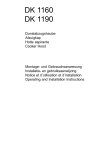
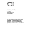
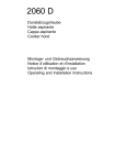
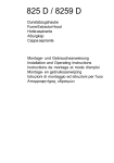
DE 3160
Dunstabzugshaube
Afzuigkap
Hotte
Cooker Hood
Montage- und Gebrauchsanweisung
Installatie- en gebruiksaanwijzing
Notice d’utilisation et d’installation
Operating and Installation Instructions
Contents
Safety warnings
For the user
For the installer
56
56
56
Description of the Appliance
Extractor version
Filter Version
58
58
59
Control Panel
60
Maintenance and care
Grease Filter
Opening the grid
Removing the filter
Charcoal filter
Changing the light bulb
61
61
61
61
62
63
What to do if
64
Special accessories
65
Technical assistance service
65
Technical Specifications
Mounting accessories included
66
66
Electrical connection
Safety warnings for the electrician
Installing the hood between cupboards with hanging rails
Installing the hood to the wall
Fixing a furniture door to the visor
67
67
68
69
70
Printed on recycled paper
AEG - putting words into action
55
Safety warnings
For the user
• The cooker hood is designed to extract unpleasant odours from the
kitchen, it will not extract steam.
• Always cover lighted elements, to prevent excess heat from
damaging the appliance. In the case of oil, gas and coal fired
cookers it is essential to avoid open flames.
• Also, when frying, keep the deep frying pan on the cooker top/cooker
under careful control.
• The hot oil in the frying pan might ignite due to overheating.
• The risk of self-ignition increases when the oil being used is dirty.
• It is extremely important to note that overheating can cause a fire.
• Never carry out any flambé cooking under the hood.
• Always disconnect the unit from the power supply before
carrying out any work on the hood, including replacing the
light bulb (take the cartridge fuse out of the fuse holder or switch off
the automatic circuit breaker).
• It is very important to clean the hood and replace the filter at
the recommended intervals. Failure to do so could cause
grease deposits to build up, resulting in a fire hazard.
For the installer
• When used as an extractor unit, the hood must be fitted with a
120mm diameter hose.
• When installing the hood, make sure you respect the following
minimum distance from the top edge of the cooking hob/ring
surfaces:
electric cookers
600 mm
gas cookers
650 mm
coal and oil cookers
700 mm min.
• The national standard on fuel-burning systems specifies a maximum
depression of 0.04 bar in such rooms.
• The air outlet must not be connected to chimney flues or combustion
gas ducts. The air outlet must under no circumstances be connected
to ventilation ducts for rooms in which fuel-burning appliances are
installed.
• The air outlet installation must comply with the regulations laid down
by the relevant authorities.
• When the unit is used in its extractor version, a sufficiently large
ventilation hole must be provided, with dimensions that are
approximately the same as the outlet hole.
56
• National and regional building regulations impose a number of
restrictions on using hoods and fuel-burning appliances connected to
a chimney, such as coal or oil room-heaters and gas fires, in the
same room.
• Hoods can only be used safely with appliances connected to a
chimney if the room and/or flat (air/environment combination) is
ventilated from outside using a suitable ventilation hole approximately
500-600 cm2 large to avoid the possibility of a depression being
created during operation of the hood.
• If you have any doubts, contact the relevant controlling authority or
building inspector’s office.
• Since the rule for rooms with fuel burning appliances is “outlet hole of
the same size as the ventilation hole”, a hole of 500-600 cm2, which
is to say a larger hole, could reduce the performance of the extractor
hood.
• If the hood is used in its filtering function, it will operate simply and
safely in the above conditions without the need for any of the
aforementioned measures.
• When the hood is used in its extractor function, the following rules
must be followed to obtain optimal operation:
— short and straight outlet hose
— keep bends in outlet hose to a minimum
— never install the hoses with an acute angle, they must always follow
a gentle curve.
— keep the hose as large as possible (preferably the same diameter
as the outlet hole).
• Failure to observe these basic instructions will drastically reduce the
performance and increase the noise levels of the extractor hood.
57
Description of the Appliance
• The hood is supplied as an extractor unit and can also be used with
a filtering function by fitting one charcoal filter.
• You will need an original AEG charcoal filter for this function
(Available from your local AEG Service Force Centre).
Extractor version
• In this version fumes are extracted to the outside via a hose
connected to the coupling ring A, placed in the outlet hole B. Fig. 1.
• In order to obtain the best performance the hose should have a
diameter equal to the outlet hole.
A
B
Fig. 1
• Depending on your installation the hose can be directed either
towards the ceiling or towards the walls. Fig. 2.
Fig. 2
58
Filter Version
• The air is filtered through a charcoal filter and returned to the kitchen.
• You will need an original AEG charcoal filter for the recirculation
function. (Available from your local AEG Service Force Centre).
• Opening the grid: Move the two sliders towards the centre (in the
“OPEN” direction) and release the grille downwards. Fig. 3
To refit the grid: it should be inserted above between the
appropriate guides until it latches into place, and after having
propped the grille to the cooker hood also in the lower part move the
two sliders outwards (in the “CLOSED” direction). Fig. 3.
E
EN
OP
CLO
SED
EN
OP
CLO
SED
Guides
E
Fig. 3
Fig. 4
E
• Insert the charcoal filter into the lugs of the frame above using the 2
red lugs E to retain it, press the red lugs inwards, and insert the
charcoal filter in the frame. Fig. 4.
• Refit the grid.
• The deflector F must be fitted over the hole B (Fig. 1) fixing it with
the screw provided. Fig. 5.
F
Fig. 5
59
Control Panel
• Best results are obtained by using a low speed for normal conditions
and a high speed when odours are more concentrated.
Turn the hood on a few minutes before you start cooking, you will
then get an under pressure in the kitchen. The hood should be left on
after cooking for about 15 minutes or until all the odours have
disappeared.
The control switches are located on the unit’s front panel:
• the light switch switches the hood lamp on and off
• the motor switch switches the cooking smoke and vapour extractor
motor on and off, enabling you to select one of the three different
speeds.
Motor switch
Light switch
The hood is also equipped with a micro-switch which can be found
under the lower runner of the visor on the right hand side.
With this micro-switch, the appliance may be automatically switched
on and off by opening and closing the pull-out panel, but only if the fan
speed has already been set and the light button is turned to “I”.
60
Maintenance and care
• The hood must always be disconnected from the electricity
supply before beginning any maintenance work.
• Never insert pointed objects in the motor’s protective grid.
• Wash the outside surfaces using a delicate detergent solution. Never
use caustic detergents or abrasive brushes or powders.
• Only ever clean the switch panel and filter grille using a damp cloth
and delicate detergents.
• It is extremely important to clean the unit and change the filters at
the recommended intervals. Failure to do so will cause grease
deposits to build up that could constitute a fire hazard.
Grease Filter
• The purpose of the grease filters is to absorb grease particles which
form during cooking and it must always be used, either in the
external evacuation or internal recycling function.
The synthetic filter is very thin (approx. 1 mm) and positioned on the
inside of its related support grille.
The filter should be changed once a month.
• The grille should be cleaned with luke warm water and non-abrasive
detergent when you change the filter.
• The grease filter can be ordered from your local ELECTROLUX
Service Force Centre.
Opening the grid
• Move the two sliders towards the centre (in the “OPEN” direction)
and release the grille downwards. Fig. 6.
To refit the grid: it should be inserted above between the
appropriate guides until it latches into place, and after having
propped the grille to the cooker hood also in the lower part move the
two sliders outwards (in the “CLOSED” direction).
Removing the filter
Remove the stops to take out the filter. Fig. 6.
• Clean the inner housing using a hot detergent solution only (never
use caustic detergents, abrasive powders or brushes).
Taquets
EN
OP
CLO
SED
EN
OP
C LO
SED
Guides
Fig. 6
61
Charcoal filter
• The charcoal filter should only be used if you want to use the hood in
the recirculation function.
• To do this you will need an original AEG charcoal filter (available from
your local Service Force Centre).
• The charcoal filter cannot be washed nor regenerated.
The charcoal filter should be replaced every 12 months under normal
use.
Replacement filters are available from your local Service Force
Centre.
Fitting the charcoal filter:
Insert the charcoal filter into the lugs of the frame above using the 2
red lugs E to retain it, press the red lugs inwards, and insert the
charcoal filter in the frame. Fig. 7.
• Removing:
Press both red lugs E upwards (towards the inside of the housing)
and remove the charcoal filter downwards. Fig. 7.
• Always specify the hood model code number and serial number
when ordering replacement filters. This information is shown on the
registration plate located on the inside of the unit.
• The charcoal filter can be ordered from your local Service Force
Centre.
E
Fig. 4
E
E
Fig. 7
62
Warning
• Failure to observe the instructions on cleaning the unit and changing
the filters will cause a fire hazard. You are therefore strongly
recommended to follow these instructions.
• The manufacturer declines all responsibility for any damage to the
motor or any fire damage linked to inappropriate maintenance or
failure to observe the above safety recommendations.
Changing the light bulb
•
•
•
•
•
Disconnect the cooker hood from the main supply.
Remove the grid. Fig. 6.
Replace the old bulb with a new one of the same type.
Refit the grid.
If the light does not come on, make sure the bulb has been inserted
correctly before contacting your local Service Force Centre.
63
What to do if
If your appliance fails to work properly please carry out the following
checks.
Symptom
Solution
The cooker hood will not start...
Check that:
The hood is connected to
the electricity supply.
Check that a fan speed has
been selected
The cooker hood is not working
effectively..
Check that:
The fan speed is set high
enough for the task.
The grease filters are clean.
The kitchen is adequately vented
to allow the entry of fresh air.
If set up for recirculation, check
that the charcoal filter is still
effective.
If set up for extraction, check that
the ducting and outlets are not
blocked.
The cooker hood has
switched off during operation...
The safety cut-out device has been
tripped.
Turn off the hob and then wait for
the device to reset.
If the hood has been installed
below the heights indicated in the
installation instructions the motor
will cut-out frequently which will
damage the hood.
If after all these checks, the problem persists, contact your local
Service Force Centre, quoting the model and serial number.
Please note that it will be necessary to provide proof of purchase for
any in-guarantee service calls.
In-guarantee customers should ensure that the above checks have
been made as the engineer will make a charge if the fault is not a
mechanical or electrical breakdown.
64
Special accessories*
Charcoal filter KLF60/80
E-Nr. 610 899 421
* Not available in UK, please contact your local Service Force Centre.
Technical assistance service (not for UK)
You are welcome to telephone our technical assistance service (see list
of technical assistance centres) whenever you need information or in the
unlikely event of a fault.
When calling, please be ready to specify:
1. The model code number
2. The serial number (E-Nr.)
3. The manufacturing number (F-Nr.)
This information is shown on the registration plate inside the unit
behind the grease filter.
We reserve the right to change specifications and colours as a result of
our policy of continuing technological development.
Service and spare parts for UK
In the event of your appliance requiring service, or if you wish to
purchase spare parts, contact your local AEG Service Force Centre by
telephoning: 08705 929 929
Your call will be automatically routed to the Service Centre covering
your post code area. For the address of your local Service Force Centre
and further information about Service Force, please visit the website at
www.serviceforce.co.uk
Please ensure that you have read the section „What to do if....“ as the
engineer will make a charge if the fault is not a mechanical or electrical
breakdown even the appliance is under warranty. Please note that
proof of purchase is required for in-guarantee service calls.
Help us to help you
Please determine your type of enquiry before writing or telephoning.
When you contact us we need to know:
• Your name
• Clear and concise details of the fault
• Address and post code • Name and model of the appliance*
• Telephone number
• E number*
* This information can be found on the rating plate, which can be seen
when the grease filters are removed.
65
Technical Specifications
Model:
DE 3160 - CHDE 3160
Dimensions: (in cm):
Height
Width
Depht
40
59,9
27
Maximum absorbed power:
200 W
Motor absorption:
Lighting:
120 W
2 x40 W
Length of the cable:
150 cm
Mounting accessories included
1 Flange Ø 100 mm
1 Flange Ø 120 mm
2 Hooks
2 rails
1 Deflector
2 Washers
4 wood-screws 5 x 45 mm
4 Wall plugs Ø 8 mm
1 Metal-screw 2,9 x 9,5
6 wood-screws 4,5x16
10 wood-screws 4,5x13
1 Spacer
66
Electrical connection
Safety warnings for the electrician
Before connecting the appliance to the power supply, check that the
voltage indicated on the rating plate corresponds to the mains power
supply available. Appliances fitted with a plug can be connected to any
standard power socket within easy access.
Should it be necessary to provide a fixed connection, the hood must only
be installed by an electrician authorised by the local electricity board.
When installing, an omnipolar disconnector with a distance of at least 3
mm between contacts must be provided.
The manufacturer declines all responsibility for malfunctions resulting from
failure to comply with the above instructions.
Electrical connection
220-230 V – by means of fixed power cable with plug.
(Fixed connection of the appliance must only be carried out by an authorised electrician.).
67
Installing the hood between cupboards with
hanging rails
• Remove the grid. Fig. 6.
• Take off the visor G. Fig. 13.
• Mount the two hanging rails directly underneath the edge of
the cupboard using three screws 4,5 x 16 mm in each rail.
Distance from first hole to front edge of the cupboards sides
must be 153 mm. Fig. 8.
153
Fig. 8
• Push the extractor hood over the two hanging rails, then fix the hood
from its inside to the cupboards sides with two screws (4,5 x 13)
through the lower holes of the hood. Fig. 9.
Fig. 9
• Refit the visor. Fig. 13.
• Refit the grid.
• Fit the spacer M on the hood with two screws O and washers,
ensure that there is not a gap between the back of the hood and the
wall by adjusting the spacer M tightly to the wall, using the screws
O. Fig. 11.
68
Installing the hood to the wall
It is possible to fix the hood in position, if necessary, by only attaching
it to the rear wall. Proceed as follows:
• Drill four Ø 8mm holes on the wall as indicated. Fig. 10.
600
34,8
35
529
509,5
Fig. 10
• Insert the four wall plugs supplied into these holes.
• Screw the two mountings hooks P into the top two wall plugs.
Fig. 11.
P
U
T
S
0-90
54-100
0-54
R
N
Fig. 11
M
O
69
• Fix the base spacer M to the wall with the two screws R 5x45
provided using either the long or the short arm, depending on the
depht of the side cupboards. Do not tighten the screws fully. Fig. 11.
• Fix the hood to the wall by means of the two hooks P
previously mounted, but first move the upper brackets S so
that the front panel of the hood, once mounted, will be in line
with the front edge of the cupboard doors. The two upper
brackets S, located at the top rear edge of the hood may be
slid backwards and forwards by loosening its fixing screws T
adjacent to them on the upper hood surface. Fig. 11.
• Check that the hood is at the right height. Minor height adjustments
may be made with the screws U embodied in the brackets. Fig. 11.
• Tighten the two wall fixing screws R, through the two access holes N
provided on the inside of the hood then fix the lower sliding frame to
the hood with two screws O and washers. Fig. 11.
Fixing a furniture door to the visor
Before fixing the furniture door to the visor, please ensure the distance
distance between the plate and the upper edge of the cabinet door is
correct (depends on the thickness of the material and whether or not
there is an upper shelf). Fig. 6.
b
a
a
b
0 = 17
16 = 33
19 = 36
Fig. 12
• Remove the grid. Fig. 6.
• Take off the visor G by turning the rear locking knobs H. Fig. 13.
70
H
G
Fig. 13
• Draw a line with a pencil on the middle of the internal side of the
furnituture door. Fig. 14.
=
=
L
Fig. 14
• Fit the visor upon the internal side of the furniture door so that the
line previously marked on it, is visible through the two triangles holes
located on the mid upper and lower side of the visor, having care to
respect the distance from the visor to the higher edge of the furniture
door as for the reason mentioned above in Fig. 12.
• Fasten the visor to the furniture door through the 8 screws L 4,5x13
mm supplied. Fig. 14.
• Replace the complete visor assembly into the extractor hood, first
inserting it on its upper, then on its lower guides.
• Turn the rear unlocking knobs H so to avoid the visor take off. Fig.
13.
• Refit the grid.
71
AEG Hausgeräte GmbH
Postfach 1036
D-90327 Nürnberg
http://www.aeg.hausgeraete.de
http://www.aeg.co.uk
© Copyright by AEG
LI1SCC Ed. 12/02