1
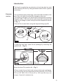
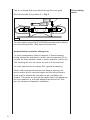
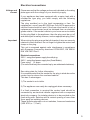
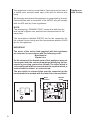
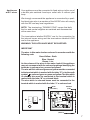
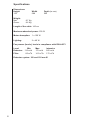
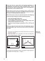
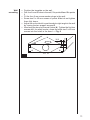
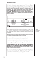
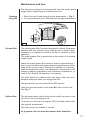
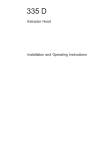
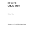
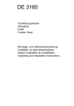
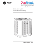
115 D
Extractor Hood
Installation and Operating Instructions
Contents
Introduction
Extractor version
Recirculating mode
3
3
4
Electrical connections
Safety warnings for electrician
5
5
Specifications
8
9
9
10
11
Hood operation
Safety warnings for user
12
12
Maintenance and care
Opening the grille
Grease filter
carbon filter
Changing the light bulb
13
13
13
13
14
Cleaning
15
Special Accessories
15
Technical Assistance Service
16
M
A
D
E
IN
G
E
R
O
M
K
A
N
O
Y
SY
ST
EM
Installation
Safety warnings for kitchen unit installer
Wall unit mounting
Wall mounting
2
Printed on recycled paper.
AEG – putting words into action.
Introduction
The hood is supplied as an extractor unit and can also be used
with a filtering function by fitting activated carbon filters (special
accessory).
Extractor
version
The unit features two outlet holes, one of which A is located on the
top of the unit while the other B is located on the rear.
To connect up the hose, you should first fit the bayonet-mounting
flange C (100 or 120 mm) on the outlet required (if using the top
outlet, fix the flange in place using the screw supplied as shown
in Fig. 1).
Close off the unused hole using the bayonet-fitting caps D.
A
D
C
¯ 100 mm
B
¯ 120 mm
1
If using the rear hole, open the air passage by removing the
partition (E — Fig. 2)
E
2
Rear Top
outlet hole outlet hole
Move the lever F to position A — Fig. 3.
When connecting up the hood using a telescopic wall pipe,
you should use a non-flammable outlet hose No. E 647 000
012 or 647 000 010 (120 mm Ø or 100 mm Ø) from our
range of special accessories.
3
The air is filtered and recirculated through the front grille.
Move the handle F to position F — Fig. 3.
EXHAUSTING
ABLUFT
EVACUATION
ASPIRANTE
MAX 40W
RECIRCULATION
UMLUFT
RECICLAGE
FILTRANTE
A
F
F
3
You will need an original AEG KLF60/80 activated carbon filter for
the recirculating mode. (See special accessories).
Summer/winter operation changeover
To avoid unnecessary outdoor transport of thermal energy
during exhaust air operation in winter, we reccommend you to
convert the fume extractor hood to winter operation (return air).
The covering foil over the return air slots is to be removed.
You also need an active carbon filter (special accessory).
When outdoor temperatures become warmer (spring), the
active carbon filter is removed again and the fume extractor
hood reset to exhaust air operation as per installation sequence. The return air slots on the upper side of the appliance
are to be sealed e.g. with self-adhesive aluminium foil. See
also for exhaust air operation installation.
4
Recirculating
mode
Electrical connections
Voltage and
current
Please ensure that the voltage and current indicated on the rating
plate agree with the voltage of your electricity supply.
If your appliance has been equipped with a mains lead with a
moulded-on type plug, you must comply with the following
regulations:
The plug moulded on to the lead incorporates a fuse. For
replacement, use a 5 amp BS1362 fuse. Only ASTA approved or
certified fuses should be used. If the fuse cover/carrier is lost, a
replacement cover/carried must be obtained from an electrical
goods retailer. If the socket outlets in your home are not suitable
for the plug fitted to the appliance, then the plug must be cut off
and destroyed for safety reasons, and an appropriate plug fitted.
Important
When wiring the plug ensure that all strands of wire are securely
retained in each terminal. Do not forget to tighten the mains lead
clamp on the plug.
This unit is screened against radio interference in compliance
with European Community directives 87/308 EEC, EN 55014/
DIN VDE 0875 Part 1.
Electrical connections
230 V - using fixed power supply line with plug.
240 V - using fixed power supply line (Great Britain).
Fuse rating 13 amps
(The unit should only be connected up by an authorized electrician).
See rating plate for further information.
It is recommended that the socket for the plug is sited above the
cooker hood or above the overhead cabinet.
This has 2 advantages:
1) The socket is not visible.
2) The appliance can easily be unplugged when necessary.
If a fixed connection is required the cooker hood should be
connected by an electrical installer registered with a competent
electricity company. An isolating device is to be provided on the
fixed wiring side. Switches with a contact opening of more than
3mm apply as isolating devices.
These include-automatic cut-out switches, fuses and contactors
(VDE 0730, s. 7, Part1).
5
Your appliance must be connected to fixed wiring via the use of
a double pole swiched fused spur outlet with or without pilot
lamp.
We strongly recommend the appliance is connected by a qualified electrician who is a member of the NICEIC who will comply
with the IEE and any local regulations.
NOTE:
The terminology “DOUBLE POLE” means that both the live
and neutral supplies are swiched and disconnected at the
same time.
The terminations labelled SUPPLY are for the connection for
the internal house wiring and the terminations labelled LOAD
are for the appliance.
IMPORTANT
The wires of the mains lead supplied with this appliance
are coloured in accordance with the following code:
Blue-Neutral
Brown-Live
As the colours of the flexible cord of this appliance may not
correspond with the coloured markings identifying the terminals in your plug, proceed as follows: The whire which is
coloured brown must be connected to the terminal which is
marked with the letter L or coloured red.
The wire which is coloured blue must be connected to the
terminal which is marked with the letter N or coloured black.
BLUE
(NEUTRAL)
BROWN
(LIVE)
L
LOAD
L
N
SUPPLY
LOAD
FUSE
ON
DP 13A, 250V
N SUPPLY
6
Appliances
with 2 wires
Appliances
with 3 wires
Your appliance must be connected to fixed wiring via the use of
a double pole swiched fused spur outlet with or without pilot
lamp.
We strongly recommend the appliance is connected by a qualified electrician who is a member of the NICEIC who will comply
with the IEE and any local regulations.
NOTE: The terminology “DOUBLE POLE” means that both
the live and neutral supplies are swiched and disconnected
at the same time.
The terminations labelled SUPPLY are for the connection for
the internal house wiring and the terminations labelled LOAD
are for the appliance.
WARNING: THIS APPLIANCE MUST BE EARTHED
IMPORTANT
The wires in this mains lead are coloured in accordance with the
following code:
Green/Yellow - Earth
Blue - Neutral
Brown - Live
As the colours of the wires in the mains lead of this appliance
may not correspond with the coloured markings identifying the
terminate in your spur box, proceed as follows:
The wire which is coloured green and yellow must be connected
to the terminal which is marked with the letter “E” or by the earth
symbol or coloured green or green and yellow.The wire which
is coloured blue must be connected to the terminal which is
marked with the letter “N” or coloured black.
The wire which is coloured brown must be connected to the
terminal which is marked with the letter “L” or coloured red.
BLUE
(NEUTRAL)
BROWN
(LIVE)
L
LOAD
L
N
FUSE
ON
SUPPLY
LOAD
DP 13A, 250V
N
SUPPLY
GREEN & YELLOW
(EARTH)
7
Specifications
Dimensions:
Height
152
Weight:
Net:
Gross:
Width
599
Depth (in mm)
505
8.7 Kg
9.6 Kg
Length of the cable: 140 cm
Maximum absorbed power: 230 W
Motor absorption: 1 x 150 W
Lighting:
2 x 40 W
Fan powers (levels), levels in compliance with DIN 44971
Level:
Min.
Extractor: 116 m3/h
Filter:
60 m3/h
Max.
175 m3/h
14 5 m3/h
Intensive
265 m3/h
175 m3/h
Extractor system: 100 and 120 mm Ø
8
Installation
Safety
warnings for
kitchen unit
installer
When used as an extractor unit, the hood must be fitted with a 100
or 120 mm diameter hose.
If the outlet hose is installed in a horizontal position, it must be
slanted at an angle of 10° so that the air can flow outside without
impediment.
When installing the hood, make sure you respect the following minimum distance from the top edge of the cooking hob/
ring surfaces:
electric cookers
650 mm
gas cookers
650 mm
coal and oil cookers
700 mm min.
The air outlet must not be connected to chimney flues or
combustion gas ducts. The air outlet must under no circumstances be connected to ventilation ducts for rooms in which
fuel-burning appliances are installed.
It is advisable to apply for authorization from the relevant
controlling authority when connecting the outlet to an unused chimney flue or combustion gas duct.
The air outlet installation must comply with the regulations
laid down by the relevant authorities.
When the unit is used in its extractor version, a sufficiently
large ventilation hole must be provided, with dimensions
that are approximately the same as the outlet hole.
National and regional building regulations impose a number
of restrictions on using hoods and fuel-burning appliances
connected to a chimney, such as coal or oil room-heaters
and gas fires, in the same room.
Hoods can only be used safely with appliances connected to
a chimney if the room and/or flat (air/environment combination) is ventilated from outside using a suitable ventilation
hole approximately 500-600 cm2 large to avoid the possibility
of a depression being created during operation of the hood.
If you have any doubts, contact the relevant controlling
authority or building inspector’s office.
Where flexible ducting is fitted the length should be no more
than:
— 3 metres with one 90° bend
— 2 metres with two 90° bends.
Bends of more than 90° will reduce the efficiency of the hood
and reduce the air flow.
9
Since the rule for rooms with fuel burning appliances is
“outlet hole of the same size as the ventilation hole”, a hole
of 500-600 cm2, which is to say a larger hole, could reduce the
performance of the extractor hood.
If the hood is used in its recirculating mode, it will operate
simply and safely in the above conditions without the need
for any of the aforementioned measures.
When the hood is used in its extractor function, the following
rules must be followed to obtain optimal operation:
— short and straight outlet hose
— keep bends in outlet hose to a minimum
— never install the hoses with an acute angle, they must
always follow a gentle curve only
— keep the hose as large as possible (100 or 120 mm Ø
min.).
Failure to observe these basic rules will drastically reduce
the performance and increase the noise levels of the extractor hood.
64
200
— Drill four 6 mm Ø holes in the base of the wall unit using the
template supplied.
— Mount the hood unit on the base of the wall unit using four
4.2 x 35 mm screws. — Fig.4
65
4
5
If using an interchangeable model, fit the plastic caps supplied in
any unused mounting holes. — Fig. 5
10
Wall unit
mounting
— Position the template on the wall.
— Drill four 8 mm Ø holes in the wall, 2 in points H and 2 in points
I.
— Fit the four 8 mm screw anchor plugs in the wall.
— Screw two 5 x 45 mm screws in points H but do not tighten
them fully home.
— Adjust the unit so that it is positioned at a right angle to the wall
by turning the two support screws G.
— Now hang the hood on the wall (holes H). Tighten the first two
screws and, for safety’s sake, screw the other two 5 x 45 mm
screws into the holes in the hood. — Fig. 6
13
H
36,5
46
Wall
mounting
G
G
I
6
11
Hood Operation
The hood is fitted with a variable speed motor. The most effective
use of the hood is obtained by switching it on a few minutes before
you start cooking and leaving it on a for approximately 15 minutes
after you have finished, thus ensuring all cooking odours are
eliminated. The control switches are located on the unit’s front
panel: the light switch switches the hood lamp on and off;
the motor switch switches the cooking smoke and vapour
extractor motor on and off, enabling you to select one of the four
different speeds.
Light switch
On/Off
6
Motor
continuous sliding
switch
Never leave a cooking hob or ring on without a pot or pan on top
of it, to avoid the possibility of excess heat damaging the unit.
Gas, oil or coal cooker flames in particular should never be left
uncovered.
Special care should be taken when using deep fat fryers since the
oil in them can overheat and burst into flames.
The risk of a fat fire increases when using dirty oil.
It is extremely important to note that overheating can cause a fire.
Never carry out any flambé cooking under the hood.
Always disconnect the unit from the power supply before
carrying out any work on the hood, including replacing the
light bulb (take the cartridge fuse out of the fuse holder or switch
off the automatic circuit breaker).
It is very important to clean the hood and replace the filter at
the recommended intervals. Failure to do so could cause
grease deposits to build up, causing a fire hazard.
12
Safety
warnings
for user
Maintenance and care
The hood must always be disconnected from the mains power
supply before beginning any maintenance work.
Opening
the grille
— Open the latch L and swing the grille downwards. — Fig. 7.
— To remove the grille, pull it forwards from the right and release it.
L
OPEN
CLOSED
7
Grease filter
M
The metal grease filter has been designed to absorb the grease
particles that are formed during cooking and is always used,
irrespective of whether the hood is set up for extractor or filter
operation.
The metal grease filter is positioned on the inside of its related
support grille.
Leave the metal grease filter panel to soak for approximately 1
hour in very hot water with grease-dissolving detergent and then
rinse it with very hot water. Repeat the operation if necessary.
Load the grease filter panel in a dishwasher, selecting the most
intensive washing programme and maximum temperature, at
least 65½C. Repeat the operation if necessary.
The grille should be cleaned with luke warm water and nonabrasive detergent when you change the filter.
The grease filter can be ordered from AEG service.
Open the grille and push on the stops M to take out the filter.
See Fig. 7.
Carbon filter
The activated carbon filter should only be used if you want to use
the hood in its recirculating mode.
To do this you will need an original AEG activated carbon filter
(see special accessories).
This filter cannot be cleaned or reused.
As a general rule, the activated carbon filter should be
13
Removing the filter
— Press the stops N and remove the filter by pulling it downwards. — Fig. 8
N
N
8
Always specify the hood model code number and serial number
when ordering replacement filters. This information is shown on
the registration plate located on the inside of the unit.
The activated carbon filter can be ordered from AEG service.
14
Failure to observe the instructions on cleaning the unit and
changing the filters will cause a fire hazard. You are therefore
strongly recommended to follow these instructions.
Warning
—
—
—
—
Changing
the light bulb
Disconnect the unit from the mains power supply.
Remove my cover
Replace the old light bulb with a new light bulb (40 W max.).
If the light does not come on, make sure the bulb has been
screwed in correctly before contacting the AEG service.
Cleaning
Warning: always disconnect the hood from the mains power
supply before cleaning it.
Never insert pointed objects in the motor’s protective grille.
Wash the outside surfaces using a delicate detergent solution.
Never use caustic detergents or abrasive brushes or powders.
Only ever clean the switch panel and filter grille using a damp
cloth and delicate detergents.
It is extremely important to clean the unit and change the filters at
the recommended intervals. Failure to do so will cause grease
deposits to build up that could constitute a fire hazard.
Special accessories
Wall box (Ø 120mm)
Wall box (Ø 100mm)
120 mm outlet hose
100 mm outlet hose
Synthetic grease filter
KLF60/80 activated carbon filter
E-Nr.647 000 016
647 000 020
647 000 012
647 000 010
660 951 157
610 899 421
15
Technical assistance service
In case of any enquiries and faults, please call AEG After-Sales Service:
AEG Domestic Appliances Limited
Head Office:
217 Bath Road
Slough, Berks SL1 4AW
Tel:
01753 872506
Telefax: 01753 512271
AEG Northern Service Centre:
Unit 20, Haigh Park
Haigh Avenue
Stockport
GL Manchester SK4 1QR
Tel:
0161 487 2205
Telefax:
0161 474 1191
AEG Scottish Service Centre:
Block 11, Unit 1
Dundyvan Industrial Estate
Coatbridge
Lanarkshire ML5 4AQ
Tel:
01236 440387
Telefax: 01236 440256
Service Appointments
Bristol:
01179 252880
Norfolk:
01603 765515
When calling please state the following
1. The model number
2. The E-No.
3. The F-No.
The manufacturer reserves the right to make alterations in design
and colour in the interests of technical development without prior
notice.
16
If your appliance has a fault, please contact our service engineer
and state the following numbers:
E-Nr. 610
F-Nr.
AEG Hausgeräte AG
Postfach 1036
D-90327 Nürnberg
© Copyright by AEG
H 260 287 140
L 489B Ed. 05/95
159/95