1
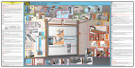
9900 Thermowayne 9600 Thermogard® 9200 Foamcore Torsion Spring Installation Instructions and Owners Manual NYLON CENTER BUSHING RIGHT HAND WOUND TORSION SPRING (RED) CENTER BEARING BRACKET LEFT HAND WOUND TORSION SPRING (BLACK) END BEARING BRACKET LEFT HAND CABLE DRUM END BEARING BRACKET TORSION TUBE RIGHT HAND CABLE DRUM REAR SUPPORT ASSEMBLY (NOT SUPPLIED) HORIZONTAL ANGLE Parts List TOP BRACKET HORIZONTAL TRACK FLAGANGLE COUNTERBALANCE CABLE #3 END HINGE CENTER HINGE VERTICAL TRACK ROLLER TL-2 JAMB BRACKET #2 END HINGE TL-1 JAMB BRACKET #1 END HINGE BOTTOM BRACKET ASTRAGAL PULL ROPE & SCREW EYE OUTSIDE STEP PLATE © Copyright 2002 Wayne-Dalton Corp. INSIDE STEP PLATE TOP BRACKET BASE TOP BRACKET SLIDE ROLLER VERTICAL TRACK TL-1 JAMB BRACKET TL-2 JAMB BRACKET TL-3 JAMB BRACKET HORIZONTAL TRACK 12 FLAGANGLE (LEFT) 12 FLAGANGLE (RIGHT) 15 FLAGANGLE (LEFT) 15 FLAGANGLE (RIGHT) 22-1/16 HORIZ. ANGLE 80 HORIZ. ANGLE (RIGHT) 80 HORIZ. ANGLE (LEFT) TORSION SPRING (RED) TORSION SPRING (BLACK) COUNTERBALANCE CABLES CABLE DRUM (RIGHT) CABLE DRUM (LEFT) END BEARING BRACKET (LEFT) END BEARING BRACKET (RIGHT) CENTER BEARING BRACKET NYLON CENTER BUSHING # 6 SCREW EYE 60 PULL ROPE # 158044 # 158046 # 154489 1 PAIR # 261965 # 261966 # 261967 1 PAIR # 240380 # 240381 # 240382 # 240383 # 292536 # 292539 # 292538 AS REQUIRED AS REQUIRED 1 PAIR # 284653 # 284654 # 279134 # 103415 # 100298 # 103336 # 100362 # 274884 NOTE: DEPENDING ON YOUR DOOR MODEL, SOME PARTS LISTED MAY NOT BE SUPPLIED IF NOT NECESSARY. PART NO. 248438 Rev.2 02/02 IMPORTANT SAFETY NOTICES Wayne-Dalton Corp. P.O. Box 67 Mt. Hope, Ohio 44660 Read these instructions carefully before attempting installation. If in question about any of the procedures, do not perform the work. Instead, have a qualified door agency do the installation or repairs. 1. Wear protective gloves during installation to avoid possible cuts from sharp metal edges. 2. It is always recommended to wear eye protection when using tools, otherwise serious eye injury could result. 3. Avoid installing your new door on windy days. Door could fall during the installation and cause damage and personal injury. 4. If the door is to be electrically operated at any time, all pull ropes MUST be removed to prevent injury or death to children who may become entangled in the rope. The locking mechanism MUST also be disengaged. 5. Operate door ONLY when properly adjusted and free of obstructions. 6. Should the door become hard to operate or completely inoperative, a qualified door agency should correct the problem to prevent damage to the door or serious personal injury. 7. DO NOT PERMIT children to play with the garage door or the electrical controls. Fatal injury could result, should the child become entrapped between the door and the floor. 8. To prevent serious injury or death, avoid standing in the open doorway or walking through the doorway while the door is moving. 9. Door is constantly under EXTREME SPRING TENSION. To prevent possible serious injury or death, adjustments, repairs, removal or installation, ESPECIALLY of SPRING ASSEMBLIES, CABLES or BOTTOM CORNER BRACKETS, should be performed ONLY by qualified door service people. 10. If your existing garage door opener does not have a reversing mechanism, you should consider purchasing one that has up to date safety features. These features can prevent opener related property damage or personal injury. 11. Check all bolted connections monthly during the lifetime of the door to prevent damage or personal injury caused by loose connections. 12. Definition of key words used in this manual: WARNING! -- Indicates a potentially hazardous situation which, if not avoided, could result in serious injury or death. IMPORTANT! -- Required step for safe and proper door operation. NOTE: -- Information assuring proper installation of the door. © Copyright 2002 Wayne-Dalton Corp. MAINTENANCE AND PAINTING INSTRUCTION FOR PREPAINTED STEEL DOORS MAINTENANCE While factory-applied finishes for steel garage doors are so durable that they will last many years longer than ordinary paints, it is desirable to clean them thoroughly on a routine basis. Apparent discoloration of the paint may occur when it has been exposed in dirt-laden atmospheres for long periods of time. Slight chalking may also cause some change in appearance in areas of strong sunlight. A good cleaning will generally restore the appearance of these coatings and render repainting unnecessary. An occasional light cleaning will also help maintain an aesthetically pleasing appearance. To maintain the original finish of the garage doors, the only regular maintenance necessary is that of annual washing. Mild solutions of detergents or household ammonia will aid in the removal of most dirt, and the following are recommended levels: One cup of Tide, or other common detergents, which contain less than 0.5% phosphate, dissolved into five gallons of warm water. NOTE: The use of detergents containing greater than 0.5% phosphate is not recommended for use in general cleaning of garage doors. CAUTION: NEVER MIX CLEANSERS OR DETERGENTS WITH BLEACH. SURFACE PREPARATION FOR PAINTING Wax on the surface must be removed or paint peeling/flaking will result. To remove this wax, it will be necessary to lightly scuff the surface with a gray (not green!) 3M ScotchBrite pad saturated with soapy water. A final wipe and rinse should be done with clean water only, to remove any loose dust or soap film. Surface scratches, which have not exposed the metal substrate, can be lightly buffed or sanded with 0000 steel wool or No. 400 sand paper to create a smoother surface. Care must be taken to not expose the substrate under the paint (see Note No. 2). Once this exposed condition exists, the likelihood for rusting is greatly increased. See the following paragraph if the metal substrate is observed. Exposed substrate must be treated to prevent rust from forming (see Note No. 2). Sand the exposed area lightly and paint with high quality metal primer to protect from corrosion. Follow drying time on primer can label before applying topcoat. The surface to be recoated must not be to smooth or the repaint material will not adhere to it (see Note No. 2). It is advisable to test a representative area to evaluate adhesion. If poor adhesion is observed, the surface must be abraded by sanding or buffing using grades mentioned above. Care must be taken to not expose the substrate under the paint. PAINTING After the surface has been properly prepared it must be allowed to dry thoroughly, then coated immediately with a premium quality latex house paint. Follow the paint label directions explicitly. Oil base paint is not recommended. Please note that if substrate is exposed, painting with latex paint may cause accelerated rusting of steel. NOTES: 1. Repainting of finish painted steel doors cannot be warranted as this condition is totally beyond door manufacturers control. 2. If the steel door surface has a finish painted textured surface representing wood grain, stucco, etc., this step should not be attempted as danger of exposing substrate is greatly increased. 3. Consult a professional coatings contractor if in doubt about any of the above directions. 4. Follow directions explicitly on the paint and solvent container labels for proper applications of coatings and disposal of containers. Pay particular attention to those directions involving acceptable conditions in which to paint. ACRYLIC GLAZING CLEANING INSTRUCTIONS: 1. To clean acrylic glazing wash with plenty of nonabrasive soap or detergent and water. Use the bare hand to feel and dislodge any caked dirt or mud. A soft, grit-free cloth, sponge or chamois may be used to wipe the surface. Do not use hard or rough cloth that will scratch the acrylic glazing. Dry with a clean damp chamois. 2. Grease and oil may be removed with kerosene or a good grade of naphtha (No aromatic content.). Users of these solvents should become familiar with their properties to handle them safely. 3. Do not use: Window cleaning fluids, scouring compounds, gritty cloths, leaded or ethyl gasolines, or solvents such as alcohol, acetone, carbon tetrachloride, etc. © Copyright 2002 Wayne-Dalton Corp. IMPORTANT! JAMBS, HEADER, AND SPRING PAD MUST BE SECURELY ATTACHED TO FRAMING MEMBERS. CHECK BEFORE INSTALLING NEW DOOR. 12 - 17 11 10 9 1 IMPORTANT! REAR SUPPORT ASSEMBLIES MUST BE SECURELY ATTACHED TO CEILING FRAMING MEMBERS ADEQUATE TO HOLD THE WEIGHT OF THE DOOR. NOTE: DOORS WITH OPERATORS, SEE STEP 21 2 8 18 IMPORTANT! DOOR OPENING PREPARATION IS CRITICAL FOR PROPER DOOR INSTALLATION. CHECK THE OPENING TOP, AND SIDES TO ENSURE IT IS LEVEL AND SQUARE. CORRECT IF NECESSARY BEFORE INSTALLING NEW DOOR. IMPORTANT! IF INSTALLING A REPLACEMENT DOOR, CHECK THE OPENING SIZE AND NEW DOOR SIZE, MAKING SURE THEY MATCH BEFORE REMOVING EXISTING DOOR. 6 NOTE: SINGLE WIDE DOOR SHOWN IN ILLUSTRATION (SOME LIGHTER WEIGHT DOORS ARE SUPPLIED WITH ONE (1) TORSION SPRING) 5 7 NOTE: SIDE LOCK INSTALLATION OPTIONAL SIDE LOCK INSTALLATION 3 19 20 NOTE: STEP PLATE OPTIONAL 4 INSTALLATION IS ON SECOND SECTION OF DOOR. SECURE THE LOCK TO THE SECTION WITH (4) 1/4-20 X 5/8 SELF DRILLING SCREWS. SQUARE LOCK ASSEMBLY WITH DOOR IMPORTANT! IT IS RECOMSECTION AND HOLE IN MENDED THAT SIDE LOCKS BE VERTICAL TRACK. THE SIDE REMOVED IF AN OPERATOR IS LOCK SHOULD BE SPACED INSTALLED ON THE DOOR. APPOX. 1/8 FROM THE SECTION EDGE. START HERE COUNTERBALANCE CABLE FOR LEFT HAND DRUM IMPORTANT! READ IMPORTANT SAFETY NOTICES AND REFER TO INSERT SHEET INSTRUCTIONS TITLED REMOVING THE OLD DOOR/ PREPARING THE OPENING. IF THE INSERT SHEET INSTRUCTIONS ARE NOT INCLUDED, CONTACT WAYNE-DALTON CORP. FOR A FREE COPY. If removing an existing door, carefully follow the directions given on the insert sheet instruction in the portion titled Removing the Old Door. ROLLER CABLE LOOP 2ND SET OF HOLES ON 9600 THERMOGARD® BOTTOM SECTION ROLLER LEFT HAND BOTTOM BRACKET 4 Uncoil the counterbalance cables and slip the loops at the ends of the cables over the milford pins on the bottom brackets of the bottom section. Place a roller in each of the bottom brackets, as well as the end hinges at the top of the section. VERTICAL TRACK 3RD SET OF HOLES ON 9200 FOAMCORE 9 3 U-BAR TOP SECTION TOP RIB 1 Assemble the Wayne-Dalton Twistlock, Slidelock track system. First, put the Twistlock tabs on the flagangle into the Twistlock holes on the vertical track. Give the flagangle 1/4 turn to lock in place. VINYL WEATHER STRIPPING TEMPORARILY NAILED TO JAMBS (REFER TO INSERT SHEET ON PREPARING THE OPENING.) TOP SECTION RIB (2) 1/4-20 CARRIAGE BOLTS AND NUTS TOP BRACKET (4) 1/4-20 x 5/8 SELF TAPPING SCREWS 8 To install the L-shaped top brackets, align the top holes in the top bracket with the first set of holes in the endcap for 9900 Thermowayne doors, second set for 9600 Thermogard® doors and third set on all 9200 Foamcore doors. Fasten using (4) 1/4-20 x 5/8 tapping screws. Secure the top bracket slide to the bracket using (2) 1/4-20 carriage bolts and nuts. Insert rollers. IMPORTANT! Right and left hand is always determined from inside the building looking out. FLAGANGLE ALIGN TAB INTO TOP HOLE IN TRACK AND TWIST UP UNTIL PARALLEL WITH TRACK TOP BRACKET SLIDE 1ST SET OF HOLES ON 9900 THERMOWAYNE WARNING! REMOVAL OF AN EXISTING DOOR CAN BE DANGEROUS. FOLLOW INSERT SHEET INSTRUCTIONS CAREFULLY, OTHERWISE SERIOUS INJURY OR DEATH COULD RESULT. Begin the installation of the door by checking the opening. It must be the same size as the door. Vertical jambs must be plumb and the header level. Side clearance, from edge of door to wall, must be minimum of 3-1/2 (89 mm) on each side. For proper opening preparation refer to the portion of the insert sheet instructions titled Preparing the Opening. MILFORD PIN 1/4-20 x 5/8 SELF DRILLING SCREW FOAMCORE II (MODEL 9200) TOP SECTION 9200 Foamcore doors over 13 wide require a 3 U-Bar. Center the U-Bar over the top rib on the top section and secure it to the section using (6) 1/4-20 x 5/8 self drilling screws. Place top section in the door opening and secure it temporarily by driving a nail into the header near the center of the door and bending it over the section. Now flip, hold and fasten the hinges. NOTE: Twistlock track components - U.S. patent no. 5,408,724 and 5,568,672. LEVEL 80 HORIZONTAL ANGLE 2 22-1/2 HORIZONTAL ANGLE (2) 5/16 x 1-5/8 LAG SCREW BOTTOM ASTRAGAL TOP SECTION 5 ALIGN TABS INTO SLOTS, PUSH TOGETHER AND TAP FORWARD WITH HAMMER HORIZONTAL TRACK Align the Slidelock tabs on the applicable horizontal angle with key slots in the horizontal track. Push the parts together. Using a hammer, tap the horizontal angle towards the curved end of the track until the hole in track and angle are aligned. Set tracks aside. NOTE: For larger size doors, a full length horizontal angle is already spot welded to the horizontal track. Before installing the bottom section, measure and cut vinyl jamb weatherstripping for entire garage door opening. Temporarily nail the weather-stripping to the door jambs and header. This will help hold the bottom door section in place. Refer to the insert sheet on preparing the opening. Now comes the single most important step in installing the WayneDalton garage door system. Center the bottom section in the door opening. Level it using wooden shims under the bottom astragal as needed. Once the bottom section is level, all the other components will automatically align. Hold the section in the opening while attaching vertical tracks. Align the bottom of the vertical tracks with the bottom of the section. If you leveled the bottom section with shims on one side, then the vertical track on that side must be raised off the floor an amount thats equal to the thickness of the shim(s). FLAGANGLE NOTE: CABLE SHOULD BE BETWEEN TRACK AND DOOR AND BEHIND ROLLERS 10 Position the flagangle 1-11/16 (43 mm) from the edge of the door. Tighten the first lag screw then secure flagangle to the jamb with (2) 5/16 x 1-5/8 lag screws. IMPORTANT! Ensure that flagangles are parallel with the door sections. IMPORTANT! The dimension between the flagangles must be exactly doorwidth plus 3-3/8 (86 mm) for smooth, safe door operation. Now complete the vertical track installation on both sides by securing center jamb bracket and tightening other lag screws. ALIGN IN PROPER HOLE AND TWIST TO BACK OF TRACK 3 COUNTERBALANCE CABLE CABLE DRUM JAMB BRACKET 3/8-16 x 3/4 TRUSS HEAD BOLT & NUT ROUND NOTCH FLAGANGLE 5/16 x 1-5/8 LAG SCREW VERTICAL TRACK BOTTOM JAMB BRACKET CENTER JAMB BRACKET BOTTOM SECTION VERTICAL TRACK Measure the length of the vertical tracks. Using the table, determine the placement of the jamb brackets for your door height. Align the Twistlock wings on each jamb bracket with the correct butterfly hole in the track and turn the jamb bracket perpendicular to the track so the mounting flange is toward the back leg of the track. 6 5/16 x 1-5/8 LAG SCREW Position the first vertical track over the rollers of the bottom section. Make sure the counterbalance cable is located between the rollers and the door jamb. Align the marks on the vertical track from step 3 with the vertical track line stamp on the endcap and loosely fasten bottom jamb bracket and flagangle with (1) 5/16 x 1-5/8 lag screw each, but do not secure the center jamb bracket yet. Install the other vertical track the same way. Run the counterbalance cables up between vertical track and edge of door section. Hang the cables over the tops of the the flagangles in round notch. IMPORTANT! The tops of the vertical tracks must be level from side to side. VERTICAL TRACK D O O R H EI G H T TL- 1 TL- 2 TL- 3 6 '0 " 64" TRACK (1626 mm) B O TTO M B O TTO M N /A 6 '5 " 69" TRACK (1753 mm) MI DDLE B O TTO M N /A 6 '6 " 70" TRACK (1778 mm) MI DDLE B O TTO M N /A 6 '8 " 72" TRACK (1829 mm) B O TTO M B O TTO M N /A 7 '0 " 76" TRACK (1930 mm) MI DDLE B O TTO M N /A 7 '3 " 79" TRACK (2007 mm) B O TTO M B O TTO M B O TTO M 7 '6 " 82" TRACK (2083 mm) MI DDLE MI DDLE MI DDLE 7 '9 " 85" TRACK (2159 mm) MI DDLE MI DDLE MI DDLE MI DDLE TO P MI DDLE TO P MI DDLE MI DDLE 8 '0 " (4 SECTI ONS) (5 SECTI ONS) 88" TRACK (2235 mm) TL-3 HOLES TL-2 HOLES TL-1 HOLES NOTE: Jamb brackets are stamped for identification. HORIZONTAL ANGLE ALIGN EDGE OF SECTIONS (2) 1/4-20 x 5/8 SELF TAPPING SCREWS FLAGANGLE 11 To install horizontal track, place the curved end over the top roller. Align the key slot in the track with the quick install tabs on the flagangle. With a pivoting motion, push the curved portion of the horizontal track downward to lock into place, while raising the rear of the horizontal to align the horizontal angle with the flagangle. Bolt the horizontal angle to the flagangle using (1) 3/8-16 x 3/4 truss head bolt and nut. Repeat for other side. With track installed you can adjust the top brackets. Vertically align the top section with the lower sections. Once aligned, move adjustable slide out to force top roller against horizontal track. Tighten 1/4-20 nuts to secure slide to top bracket. Repeat for other side. Remove nail that was temporarily holding top section in place. IMPORTANT! Failure to remove nail before attempting to raise door could cause permanent damage to top section. DO NOT ATTEIMPT TO RAISE DOOR AT THIS POINT. WARNING! (3) 1/4-20 x 5/8 SELF TAPPING SCREWS END HINGE #1 ON BOTTOM SECTION CENTER NOTE: HINGE IDENTIFY LOCK SECTION BY THE #2 STAMP ON THE END HINGE DO NOT RAISE DOOR UNTIL HORIZONTAL TRACKS ARE SECURED AT REAR AS OUTLINED IN STEP #18, OR DOOR COULD FALL FROM OVERHEAD POSITION CAUSING SEVERE INJURY OR DEATH. 5/16 X 1-5/8 LAG SCREW 7 Make sure top leaves of all hinges on the bottom section are folded down. Insert rollers into the end hinges of the second section, also called the lock section. With assistance lift section and place rollers over the tops of the vertical tracks. Install by guiding rollers into the vertical track on both sides and gently lowering this section onto the bottom section. Keeping the ends of the sections aligned, install remaining section(s), except top section, in same manner. Fasten all hinges to connect the sections by flipping up the hinge leaf, holding it firmly against section and driving in the supplied 1/4-20 x 5/8 self tapping screws. NOTE: Two (2) 1/4-20 x 5/8 self tapping screws are used for each end hinge leaf, while three (3) screws are used for each center hinge. The screw placement is staggered in the end hinges, with the screw nearest the edge of the door going into the lower hole and the inside screw going into the upper hole. IMPORTANT! Once fastener is snug against hinge leaf, tighten an additional 1/4 to 1/2 turn to achieve maximum design holding power. NOTE: To install lock, see lock instructions included in the lock assembly bag. UPPER SLOTS USED ON 15 RADIUS TRACK FLAGANGLE (2) 3/8 - 16 HEX NUTS LOWER SLOTS USED ON 12 RAD. TRACK JAMB LEFT HAND END BEARING BRACKET (2) 3/8-16 x 3/4 TRUSS HEAD BOLT HORIZONTAL ANGLE 12 Attach the left hand end bearing bracket to the horizontal angle with (2) 3/8-16 x 3/4 truss head bolts and nuts. Once the bracket is secured, fasten the bracket to the jamb with (1) 5/16 x 1-5/8 lag screw. Repeat for the right hand side. NOTE: End bearing brackets are to be attached using the lower slots on 12 radius track and using the upper slots on 15 radius track. IMPORTANT! Right and left hand are always determined from inside the building looking out. CENTER BEARING BRACKET 5/16 x 1-5/8 LAG SCREW HORIZONTAL PENCIL LINE 13 SPRING WARNING LABEL CENTER BEARING BRACKET SPRING WITH RED COLOR CODED WINDING CONE: RIGHT HAND WOUND (MOUNTS ON LEFT SIDE) (2) 3/8-16 x 1-1/4 BOLT 15 WINDING BARS (2 REQUIRED) TORSION TUBE VERTICAL PENCIL LINE (CENTERLINE OF THE DOOR) TAMPER-PROOF LAG SCREW 5/16 x 2 OR 5/16 x 1-5/8 SPRING PAD OVER MASONRY Locate the center of the door and mark a vertical pencil line on the spring pad. Then measure the distance from the center of the mounting hole in the end bearing bracket to the top of the door. Using that same distance, mark a horizontal line on the spring pad, measuring up from the top of the door. Position the center bearing bracket along the vertical pencil line on the spring pad as shown. In addition, position the center bearing bracket halfway over the horizontal pencil line. This will level the torsion tube through the end bearing brackets when installed. Attach the center bearing bracket to the spring pad using (2) 5/16 x 15/8 lag screws and (1) 5/16 x 2 tamper-proof lag screw. IMPORTANT! Use the 5/16 x 1-5/8 tamper-proof lag screw ONLY if spring pad is mounted over masonry. IMPORTANT! Tamper-proof lag screw MUST be attached through the bottom hole of the center bearing bracket. NYLON CENTER BUSHING WINDING CONE 14 RIGHT HAND WOUND RED WINDING CONE LEFT HAND SIDE Facing the inside of the door, lay the torsion tube on the floor. Lay the black color coded winding cone with spring and cable drum on the floor at the right end of the tube. Then lay the red color coded winding cone with spring and cable drum on the floor at the left end of the tube. NOTE: Right and left hand is always determined from inside the building looking out. NOTE: Some lighter weight doors are provided with only (1) torsion spring. Identify the spring(s) provided as either right hand wound (red winding cone), which goes on the LEFT HAND SIDE or left hand wound (black winding cone), which goes on the RIGHT HAND SIDE. NOTE: The set screws used on all Torsion Counterbalance cable drums and winding cones are now painted red. DO NOT identify right and left hand side by the set screws. Slide the nylon center bushing onto the torsion tube followed by the spring(s) and cable drums. The nylon center bushing, spring(s), and cable drums must be positioned as shown in the illustrations. With assistance, pick up the torsion tube assembly and slide the other end the of tube through one end bearing bracket. Lay the torsion tube into the center bearing bracket and slide the loose end of the tube into the opposite end bearing bracket. Position the torsion tube so that equal amounts of the tube extend from each end bearing bracket. STATIONARY SPRING CONE NYLON CENTER BUSHING SPRING WARNING LABEL Slide the nylon center bushing into the end of (1) stationary spring cone and align the cone(s) with the holes in the center bearing bracket. Secure the spring(s) to the center bearing bracket with (2) 3/8-16 x 1-1/4 bolts and nuts. IMPORTANT! Springs under tension can be dangerous. Spring warning tag must be attached to center bearing bracket in obvious sight. If this tag is missing, contact Wayne-Dalton Corp. for free replacements. Clamp locking pliers onto both vertical tracks just above the third roller. This is to prevent door from raising while winding the spring(s). WARNING! FAILURE TO CLAMP TRACK CAN ALLOW DOOR TO RAISE AND CAUSE SEVERE INJURY OR DEATH. RIGHT CABLE DRUM (BLACK) LEFT HAND WOUND BLACK WINDING CONE RIGHT HAND SIDE SET SCREW (2) 3/8-16 NUT COUNTERBALANCE CABLE TORSION TUBE CRIMPED CABLE BUTTON RED CABLE DRUM LEFT HAND SIDE 90° BEND LOOSE CABLE BUTTON 16 Thread the counterbalance cables behind the rollers and around the back side of the cable drums. Before hooking the counterbalance cables into the cable drums, slide the loose cable buttons against the crimped buttons and with a pair of pliers, bend a 90 degree angle in the counterbalance cable. Hook the counterbalance cables into the cable drums. Slide the left hand cable drum against the left hand end bearing bracket and tighten the set screws in the cable drum. Rotate the left hand cable drum until the counterbalance cable is taut. CABLE ENDS MUST WRAP DRUM 1/2 TO 3/4 TURN. Clamp locking pliers to the torsion tube and brace it against the jamb to hold the counterbalance cable taut. Slide the right hand cable drum against the right hand end bearing bracket and rotate the cable drum until the counterbalance cable is taut. Tighten the set screws in the cable drum. IMPORTANT! Tighten set screws one (1) full turn after making contact with the torsion tube. Counterbalance cable tension MUST be equal for both sides. WINDING CONE 17 SET SCREWS (TORQUE TO 14-15 ft-lbs.) Position a ladder slightly to the side of spring so that the winding cone is easily accessible, yet your body is not in the path of the winding bars. Check the tag(s) attached to the spring(s) for the number of required spring turns. 60 Door Height 65 Door Height 66 Door Height 68 Door Height 70 Door Height 73 Door Height 76 Door Height 79 Door Height 80 Door Height = = = = = = = = = Approx. 6-3/4 Turns Approx. 7 Turns Approx. 7-1/4 Turns Approx. 7-1/4 Turns Approx. 7-1/2 Turns Approx. 8 Turns Approx. 8 Turns Approx. 8-1/4 Turns Approx. 8-1/2 Turns Inserting winding bars into holes of winding cone, one after the other, rotate winding cone upward toward ceiling 1/4 turn at a time until correct number of turns for your door height is achieved. As the last 1/4 turn is achieved, insert winding bar in the bottom hole of the winding cone and gradually let tension OFF the spring, allowing the lower bar to rest against the door and support all of the spring tension. Stretch the spring 1/4 towards the edge of the door to create clearance between the spring coils, allowing for smooth operation. Tighten the set screws on the winding cone to 14 -15 ft.-lbs. of torque. Carefully push the upper bar toward the ceiling just enough to free the lower bar, then SLOWLY remove the upper bar. If required, repeat for the other side. IMPORTANT! Pushing the upper bar too far will cause the counterbalance cables to fall off the cable drums. Hold the door down to prevent it from rising unexpectedly, in the event the spring(s) were overwound, and carefully remove the locking pliers from the vertical tracks. Raise the door until the top section and half of the next section are in a horizontal position. Do not raise door any further since rear of horizontal track is not yet supported. WARNING! RAISING DOOR FURTHER CAN RESULT IN DOOR FALLING AND CAUSE SEVERE INJURY OR DEATH. Now clamp a pair of locking pliers to the vertical tracks just above the second roller on one side, and just below the second roller on the other side. This will prevent the door from raising or lowering while installing the rear support. PERFORATED ANGLE (NOT SUPPLIED) Wayne-Dalton Corp. P.O. Box 67, Mt. Hope, Ohio 44660 www.wayne-dalton.com 9900 Thermowayne 9600 Thermogard® 9200 Foamcore LIFETIME LIMITED WARRANTY The Manufacturer warrants the 9900 THERMOWAYNE, 9600 THERMOGARD and 9200 FOAMCORE insulated garage door for as long as you own the door from the time of installation against structural failure (rendering the door inoperable) of the door sections due to separation/ degradation of foam insulation. Other conditions and exceptions as contained herein apply. 5/16 x 2 LAG SCREWS (NOT SUPPLIED) 5/16 x 1-1/4 BOLT AND NUT (NOT SUPPLIED) HORIZONTAL TRACK The Manufacturer warrants the steel skin of the9900 THERMOWAYNE, 9600 THERMOGARD and 9200 FOAMCORE insulated garage door for as long as you own the door from the time of installation against deterioration such as cracking or splitting due to rust-through. Other conditions and exceptions contained herein apply. The Manufacturer warrants the garage door hardware and track, excluding springs, for as long as you own the door against defects in workmanship or material from time of installation. After a period of TWENTY YEARS from time of installation, replacement of LIFETIME LIMITED WARRANTY materials are prorated at 50 percent of Manufacturers published pricing at time of claim. This warranty extends only to the original homeowner, providing the door is installed in his/her place of primary residence. It is not transferable. The warranty applies to residential property only and is not valid on commercial or rental property. The Manufacturer warrants that any parts of the door not covered by the above limited warranty will be free from defects in workmanship and material for ONE YEAR from the time of installation. The Manufacturer shall, upon notification, correct any nonconformity at its option, by repairing, replacing, or refunding original purchase price of any defective part(s). This warranty covers material only and excludes all other charges incurred. NO EMPLOYEE, DISTRIBUTOR, OR REPRESENTATIVE IS AUTHORIZED TO CHANGE THE FOREGOING WARRANTIES IN ANY WAY OR GRANT ANY OTHER WARRANTY ON BEHALF OF MANUFACTURER. The Manufacturer shall not be responsible for any damage resulting to or caused by its products by reason of installation, improper storage, unauthorized service, alteration of products, neglect or abuse, or attempt to use the products for other than the customary usage or for their intended purposes. The 9900 THERMOWAYNE, 9600 THERMOGARD and 9200 FOAMCORE warranty becomes null and void if the door is punctured with any hole or if a hole is drilled into the door sections other than those specified in the notes of installation. This warranty does not cover the product due to circumstances such as normal wear, damage from corrosive fumes or substances, fire, condensation, vandalism, acts of God, or other causes beyond Manufacturers control, nor replacement or repair labor. THIS WARRANTY COVERS A CONSUMER PRODUCT AS DEFINED BY THE MAGNUSON-MOSS WARRANTY ACT. NO WARRANTIES, EXPRESSED OR IMPLIED, (INCLUDING, BUT NOT LIMITED TO, THE WARRANTY OF MERCHANTABILITY OR FITNESS FOR A PARTICULAR PURPOSE), SHALL EXTEND BEYOND THE APPLICABLE TIME PERIOD STATED IN BOLD FACE TYPE ABOVE. 18 IMPORTANT! ANGLE MUST BE ATTACHED TO FRAMING MEMBER ADEQUATE TO SUPPORT DOOR WEIGHT WITH 5/16 x 2 LAG BOLTS 5/16 x 1-1/4 BOLT AND NUT (NOT SUPPLIED) EXTEND BOLT THROUGH TRACK Using perforated angle, fabricate rear support for horizontal tracks as shown. Using lag screws, make sure that support is fastened into ceiling joist, or adequate framing members to hold the weight of the door. Keeping the horizontal track parallel to the edge of the door sections, raise the horizontal track to a level position and bolt it to the rear support structure. Track must be secured and braced to prevent movement. The bolt should extend into the track to act as a roller stop. Repeat for other side. Remove locking pliers and close door. WARNING! KEEP HORIZONTAL TRACK PARALLEL AND WITHIN 3/4 (19 mm) OF DOOR EDGE, OTHERWISE DOOR COULD FALL, RESULTING IN SERIOUS INJURY OR DEATH. Permanently attach the vinyl weather stripping to both door jambs and the header. Now, lift the door and check its balance. Unwind spring(s) if door lifts by itself or if it is hard to pull down. Wind spring(s) if door is difficult to lift or too easy to pull down. To adjust spring tension, fully close door. Apply locking pliers to track above third roller. Insert a winding bar into the winding cone. Push upward on the winding bar while carefully loosening the set screws in the winding cone. BE PREPARED TO SUPPORT THE FULL FORCE OF THE TORSION SPRING ONCE THE SET SCREWS ARE LOOSE. Claims for defects in material and workmanship covered by this warranty shall be made in writing to the dealer from whom the product was purchased within the warranty period. Manufacturer may either send a service representative or have the product returned to the Manufacturer at Buyers expense for inspection. If judged by Manufacturer to be defective in material or workmanship, the product will be replaced or repaired at the option of Manufacturer, free from all charges except authorized transportation and replacement labor. NOTE: On doors with one spring, it will be necessary to clamp the torsion tube with locking pliers to keep counterbalance cables on cable drums BEFORE loosening set screws. THE REMEDIES OF BUYER SET FORTH HEREIN ARE EXCLUSIVE AND ARE IN LIEU OF ALL OTHER REMEDIES. THE LIABILITY OF MANUFACTURER, WHETHER IN CONTRACT, TORT, UNDER ANY WARRANTY, OR OTHERWISE, SHALL NOT EXTEND BEYOND ITS OBLIGATION TO REPAIR OR REPLACE, AT ITS OPTION, ANY PRODUCT OR PART FOUND BY MANUFACTURER TO BE DEFECTIVE IN MATERIAL OR WORKMANSHIP. MANUFACTURER SHALL NOT BE LIABLE FOR COST OF REMOVAL OR INSTALLATION OR SHALL NOT BE RESPONSIBLE FOR ANY DIRECT, INDIRECT, SPECIAL OR CONSEQUENTIAL DAMAGES OF ANY NATURE. IMPORTANT! Pushing the winding bar too far will cause the counterbalance cables to fall off the cable drums. This warranty gives you specific legal rights, and you may also have other rights, which may vary from state to state. However, some states do not allow limitations on how long an implied warranty lasts or the exclusion or limitation of incidental or consequential damages, so the above limitations or exclusions may not apply to you. © Copyright 2002 Wayne-Dalton Corporation Carefully adjust spring tension 1/4 turn. Retighten both set screws in the winding cone and if required, repeat for the other side. Recheck door balance DO NOT ADJUST MORE THAN 1/2 TURN FROM THE RECOMMENDED NUMBER OF TURNS. If the door still does not operate easily, lower the door into the closed position, UNWIND THE SPRING(S) FULLY (Reference the insert sheet Removing the Old Door/Preparing the Opening section on Torsion Spring Removal), and recheck the following the items: 1.) 2.) 3.) 4.) 5.) 6.) Check the door for level. Check the torsion tube for level. Check the track spacing. Check the counterbalance cables for equal tension. Check for track for potential obstruction of the rollers. Clamp locking pliers onto track and rewind spring(s). 2nd HOLE AT 2-3/16 (56 mm) FROM 1st HOLE TYPICAL OPERATOR BRACKET (SUPPLIED WITH OPERATOR) BOTTOM SECTION (OUTSIDE) BRIDGE POINT IMPORTANT! If door still does not operate properly, then contact a qualified door agency. 1st HOLE AT 1 (25 mm) FROM BOTTOM OF SECTION SCREWS (SUPPLIED WITH OPERATOR) OUTSIDE STEP PLATE 20 To install the step plate raise the door to a comfortable working height and secure with locking pliers to the track. Locate the step plate in the center of any stile on a raised panel door. Make one mark 1 (25 mm) up from the bottom edge and another mark 2- 3/16 (56 mm) up from the first mark. Drill a 7/16 (11 mm) hole through the section at each mark and insert the step plate. Loosely fasten step plate slide to base with (1) 1/4-20 x 1/2 carriage bolt and nut. Align inside step plate holes and fasten from inside using the #8 screws provided. Install one #8 x 3/4 screw in the bottom step plate hole. In the top hole use the #8 x 3/4 screw when attaching step plates to 9200 Foamcore, use the #8 x 1 screw when attaching step plates to 9600 Thermogard® and use the #8 x 1-1/2 screw when attaching step plates to 9900 Thermowayne. Tighten 1/4-20 carriage bolt and nut. SCREW EYE AT 48 TO 50 (1220 to 1270 mm) FROM FLOOR NOTE: Step plates are optional on 9900 Thermowayne, 9600 Thermogard®, and 9200 Foamcore door models. PULL ROPE BOTTOM SECTION (INSIDE) TIE PULL ROPE TO BOTTOM BRACKET INSIDE STEP PLATE BASE TYPICAL OPERATOR ARM (SUPPLIED WITH OPERATOR) #8 x 9200 #8 x 9600 #8 x 9900 3/4 SCREW FOAMCORE 1 SCREW THERMOGARD 1-1/2 SCREW THERMOWAYNE SEE OPERATOR INSTRUCTIONS FOR DETAILS ON INSTALLATION OPERATOR MUNTIN 21 INSTALLATION TIPS: 1. Follow the installation instructions supplied with your operator. 2. Reinforce top section per manufacturers recommendation prior to attaching operator. 3. Install trolley rail 1 to 1-1/2 (25 - 38 mm) above high arc of top section of the door. 4. Mount operator to ceiling so that 1 to 1-1/2 (25 - 38 mm) clearance is maintained between trolley rail and top section when door is fully open (trolley rail will slope down towards rear). 5. The operator bracket must be mounted to the operator muntin on the top section so it bridges the transition point in section thickness. WARNING! OPERATOR MUST BE TESTED AT TIME OF INSTALLATION AND MONTHLY THEREAFTER TO ENSURE THAT DOOR REVERSES ON CONTACT WITH 2 X 4 BOARD LAID FLAT UNDER THE DOOR. FAILURE TO ADJUST OPERATOR, IF NECESSARY, CAN RESULT IN SEVERE INJURY OR DEATH. IF YOUR OPERATOR IS EQUIPPED WITH PHOTOELECTRIC SYSTEM, THEN THIS MUST BE TESTED AT THE SAME TIME TO ENSURE THAT DOOR DOES NOT CLOSE AND A CLOSING DOOR OPENS IF SYSTEM IS OBSTRUCTED. FAILURE TO MAKE ADJUSTMENTS, IF NECESSARY, CAN RESULT IN SEVERE INJURY OR DEATH. INSIDE STEP PLATE SLIDE #8 x 3/4 SCREW 1/4-20 X 9/16 CARRIAGE BOLT AND WHIZ NUT INSTALL FRONT OF TROLLEY RAIL 1 TO 1-1/2 (25 - 38 mm) ABOVE HIGHARC OF DOOR IMPORTANT! ANGLE MUST BE ATTACHED TO FRAMING MEMBER(S) 19 Twist the No. 6 screw eye into the wood jamb approximately 48 to 50 (1220 to 1270 mm) from the floor. Tie the pull rope to the screw eye and to the bottom bracket as shown. WARNING! DO NOT INSTALL PULL ROPES ON DOORS WITH ELECTRIC OPERATORS. CHILDREN MAY BECOME ENTANGLED IN THE ROPE CAUSING INJURY OR DEATH. TYPICAL OPERATOR INSTALLATION If you are installing an electric operator on your door, the following information is provided to ensure proper function of your door/operator installation. Figure 21 shows a typical means of connecting the operator arm to the operator stile located in the center of the top section. ATTACH OPERATOR TO CEILING USING PERFORATED ANGLE ATTACH OPERATOR RAIL SECURELY TO SPRING PAD INSTALL TROLLEY RAIL 1 TO 1-1/2 (25 - 38 mm) ABOVE DOOR WHEN FULLY OPEN (RAIL WILL SLOPE DOWN)