1
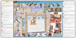
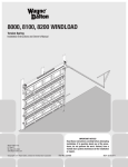
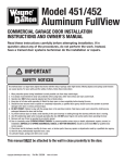
TorqueMaster™ & idrive™
9900/9600/9200/9100
INSTALLATION INSTRUCTION
SUPPLEMENT
When installing an idrive™ opener with this door use
this supplement to the main door instructions as follows:
1) Begin with Step 1 of the main door instructions.
2) Replace Step 8 of the main door instructions with
Step 8 of the attached supplement.
3) Replace Steps 12 through 17* of the main door instructions with the Steps 12 through 17b of the attached
supplement.
*Supplement replaces Steps 12 - 18 on single spring doors
© Copyright 2002 Wayne-Dalton Corp.
1
Part No. 301528
New
07/02
®
TorqueMaster™ & idrive™
9900 Thermowayne™
9600 Thermogard®
9200/9100 Foamcore™
INSTALLATION INSTRUCTIONS INSERT
Follow the corresponding steps in this insert with the steps in the installation manual provided with the door. These
modifications are designed to accommodate the new idrive™ garage door opener.
8
Top Bracket Installation
To install the L-shaped top brackets, align the top holes in the top bracket with the first set of holes in the endcap for 9900
Thermowayne™ doors and second set of holes for 9600 Thermogard® doors and 9200/9100 Foamcore™ doors. Fasten
using (4) 1/4-20 x 5/8” self tapping screws. Secure the top bracket slide to the bracket using
(2) 1/4-20 x 5/8” carriage bolts and nuts. Insert rollers. (see Fig. 1)
NOTE: To differentiate between a 9900 Thermowayne™, 9600 Thermogard® and 9200/9100 Foamcore™ door models, look for the following characteristics:
1) 9900 Thermowayne™
(below) will have painted hardware (top brackets, bottom brackets, end caps, etc.) with a steel
backing on the sections.
2) 9600 Thermogard® (right)
will have galvanized hardware, with
a steel backing on the sections.
GALVANIZED
HARDWARE
STEEL
BACKING
PAINTED
HARDWARE
STEEL BACKING
TOP SECTION
RIB
(2) CARRIAGE
BOLTS
3) 9200/9100 Foamcore™
(below) will have galvanized hardware, with a laminated (soft) backing on the sections.
GALVANIZED
HARDWARE
1ST SET OF HOLES ON
9900 THERMOWAYNE™
TOP
BRACKET
SLIDE
2ND SET OF HOLES ON
9600 THERMOGARD®
AND
9200/9100 FOAMCORE™
TOP
BRACKET
(2) HEX
NUTS
ROLLER
LAMINATED
(SOFT) BACKING
FIG. 1
2
(4) SELF-TAPPING
SCREWS
The idrive™ garage door opener is best installed in combination with the door installation steps. Refer to this
idrive™ installation insert when you reach Step 12 TorqueMaster™ installation, in the main door installation instructions and
owners manual. When instructed to slide the center bracket/bushing onto the torque tube, replace that step with the following instructions below, which will provide the steps necessary to install the TorqueMaster™ system, as well as the preliminary
installation steps for the idrive™ garage door opener.
12
Power Head Assembly
OPENER POWER
HEAD
Lay the torque tube on the floor (inside garage) in front
of the door with the labeled end to the left. NOTE:
Opener will not slide over a torque tube label.
Attempting to slide opener over the left end of the torque
tube can damage the internal electronics.
NOTE: Hold opener by the main body. Do NOT hold
by the motor.
Look into the opener’s left side to ensure the left hand bearing
and the internal (black) sleeve are aligned with the torque
tube profile. Once aligned, slide the opener power head
onto the right hand end of the torque tube. As the right end
of the torque tube enters the internal (black) sleeve, rotate
the opener back and forth slightly to help aid alignment.
NOTE: Do not force the opener onto the torque tube
if misalignment occurs.
LEFT HAND
BEARING
FIG. 3
OPENER
POWER
HEAD
OPENER POWER HEAD
TORQUE TUBE AND
BEARINGS PROFILES
ALIGNED
FIG. 4
RIGHT HAND
BEARING
PLUG MOTOR
INTO THE OPENER SLIDE OPEN
ER
POWE
POWER HEAD
R HEA
D
FIG. 2
Continue sliding the opener power head onto the torque
tube. Align the right hand bearing with the torque tube and
slide the opener power head completely onto the torque
tube until the torque tube exits the opener power head’s
right hand bearing. Continue sliding the opener power head
to the center of the torque tube and plug the motor into the
opener power head.
LABEL
(LEFT SIDE)
TORQUE TUBE
TORQUE
TUBE
IMPORTANT! Right and left hand are always
determined from inside the garage looking out.
MOTOR
INSERT THIS END FROM LEFT SIDE OF
OPENER
FIG. 5
3
17b
Drum Wrap Installation
FRONT HALF
DRUM
OUT BOARD
CATCH
INBOARD
SNAP
BACK HALF
FLAGANGLE
APPLY
PRESSURE
UNDERNEATH
WITH THE
THUMB AND
FINGERS
WRAPPED
OVER TOP
OF
SNUBBER.
TIGHT JOINT
FIG. 21
Locate right hand drum wrap. Slide back half of the drum wrap behind drum placing the right end wall between the
drum and flag angle. Close front half of the drum wrap around drum, engage inboard snap and press firmly until a
distinct snap is felt. Outboard catch must be engaged as shown. Confirm both snap and catch are fully engaged by
lightly tugging against them. Repeat for the left side.
Refer back to the main door manual and continue door installation at the
REAR SUPPORT INSTALLATION Step 18. (Step 19 in the Single Spring
TorqueMaster™ Installation Instructions)
After door installation is completed, refer to the idrive™ owner’s manual,
starting at the PRE-OPERATION INSTALLATION section to complete
the opener installation.
NOTE: Refer to the main door manual for counterbalance adjustments.
8
REAR SUPPORT INSTALLATION
PERFORATED
ANGLE (NOT
SUPPLIED)
HORIZONTAL
TRACK
13
14a
Drum Installation
Drive Gear/End Bracket Installation
Ensure that torque tube is centered and level with door.
Shake the torque tube gently to extend the winding shafts
out about 5" on each side. For single spring applications,
there will be no left hand winding shaft in the torque tube.
Lift the torque tube and rest on top of flagangles. Orient
torque tube so that back of opener is flat against header/
spring pad. See Figure 12
Cable drums and torque tube are cam shaped to fit together
only one way. To install the cable drum, slide the drum
over the winding shaft until the drum seats against the torque
tube. The winding shaft must extend past the drum far
enough to expose the splines and the groove. Align the
winding shaft groove with the round notch in the flagangle.
Repeat for opposite side.
Beginning with the right hand side, lubricate entire
circumference of the drive gear with the oil provided in
the packet. Slide the drive gear onto the winding splines
until it touches the flagangles.
NOTE: No drive gear is required for the left side on
single spring applications.
DRUM
WINDING SHAFT
OIL PACKET
NOTE: On single spring applications, take care in
handling the loose winding shaft (left side) so that it
does not slide back into the torque tube.
TORQUE TUBE
FIG. 9
WINDING SHAFT
FIG. 6 DRUM
Single Spring Applications: Insert the left hand loose
winding shaft into the left hand drum prior to sliding the
drum over the torque tube.
DRIVE GEAR
INSTALLED
TORQUE TUBE
LOOSE WINDING SHAFT
DRUM
FIG. 7
FIG. 10
WINDING
SHAFT GROOVE
END BRACKET
SPLINES
FLAG ANGLE
ROUND
NOTCH
(2) 1-5/8” LAG
SCREWS
FIG. 11
FIG. 8
4
DRIVE GEAR
Using the emergency disconnect, pull disconnect handle
downwards and place it in the manual door operated
position. Use disconnect label for reference. Motor
will be rotated 90° from its packaged position.
Ensure counterbalance cable tension is equal for both sides
prior to fully winding spring(s) to appropriate number of
turns.
Carefully rotate the winding bolt head clockwise until the
counter show the correct number of turns for your door.
See the chart below. Repeat for the opposite side on double
spring TorqueMster™ systems.
If door raises off of floor remove 1/2 - 1 full turn from
each spring before proceeding.
NOTE: If motor does not pivot 90°, see troubleshooting
section in the idrive™ main installation manual.
16b
Cable Adjustments
DRUM
After spring is wound, hold the lock nut stationary with a
7/16” wrench while rotating the winding bolt clockwise until
snug. Tightening of the lock nut prevents spring from
unwinding. Repeat for opposite side if necessary.
CABLE
PULL
CABLE
Door Height = Spring Turns
SET SCREW
FIG. 19
6’0” Door Height = 14-1/2 turns (Double
Spring) and 15 turns (Single Spring)
6’-3” Door Height = 15 turns
6’-5” Door Height = 15-1/2 turns
6’-6” Door Height = 15-1/2 turns
6’-8” Door Height = 16 turns
6’-9” Door Height = 16 turns
7’-0” Door Height = 16-1/2 turns
7’-3” Door Height = 17 turns
7’-6” Door Height = 17-1/2 turns
7’-9” Door Height = 18 turns
8’-0” Door Height = 18-1/2 turns
FIRST
GROOVE
Adjust the counter balance cables by rotating the drum until
the set screw faces directly away from the header. Loosen
the set screw no more than 1/2 turn. Pull on the end of the
cable to remove all cable slack. Check to ensure the cable
is aligned and seated in the first groove of the cable drum.
Snug the set screw, then tighten an additional 1-1/2 turns.
Cut off excess cable.
17a
IMPORTANT! Adjustments to the recommended number
of turns may be required. AFTER REAR SUPPORT
ASSEMBLY IS COMPLETE (located in main door manual
instructions), check door balance. If door raises off of floor
under spring tension alone, then reduce turns until door will
rest on floor. A “hot” door such as this can cause idrive™
operation problems.
Wind Counterbalance Springs
Clamp locking pliers onto both vertical tracks just above
third roller. This is to prevent garage door from rising while
winding counterbalance springs.
IMPORTANT! DO NOT USE IMPACT GUN TO
WIND SPRING(S)
LOCK NUT
Beginning with the right hand side. Press and hold in the
canoe clip. Ensure the cable is in the first groove of the
drum. Using an electric drill (high torque gear reduced to
1300 RPM preferred) with a 7/16" socket, carefully rotate
right hand winding bolt clockwise, until counter shows 2-3
turns. This will keep the counterbalance cable taut while
adjusting the left hand side counterbalance cable.
Repeat for left side on double spring TorqueMaster™
systems.
Single spring applications will require no spring pre-winding.
7/16” WRENCH
CONOE CLIP
WINDING BOLT
FIG. 20
7
COUNTER
Slide the right hand end bracket over the drive gear. Attach
end bracket and the flagangle to the jamb with (2) 5/16 x
1-5/8” lag screws. (see Fig. 11)
14b
15
Counter Installation
Locate the spring pad. The spring pad is a vertical running
board directly above the door. Remove (2) 1/4-20 flange
nuts from bottom of opener power head. NOTE: Do not
discard flange nuts. Place the support bracket underneath
opener power head, to the right side of motor, centered on
spring pad.
Level the torque tube to the top of the door section with the
idrive™ resting on the support bracket. Once torque tube
is level, secure support bracket to the spring pad with (2)
1/4 x 2" lag screws.
END BRACKET
COUNTER
GEAR
RAISED
RIB
MISSING TOOTH
(TOWARD OUTSIDE)
“0”
FIG. 12
Power Head/
Support Bracket Installation
RIGHT HAND
COUNTER
COVER
ASSEMBLY
OPENER SPRING PAD
POWER
HEAD
Begining with the right side, install the counter gear with the
missing tooth toward the outside, away from the end bracket.
Press the counter gear onto the end bracket until snaps
engage. Select the right hand counter cover assembly and
align the hex of the counter cam with the end of the winding
shaft. Also, align the “0” on the counter cover with the
raised rib on the end bracket. Press the counter cover
assembly against the counter gear until it locks into place.
MOTOR
Repeat the Drive Gear/End Bracket Installation and
Counter Installation sections for the left hand side
installation.
TORQUE TUBE
SUPPORT
BRACKET
(2) 2” LAG SCREWS
FIG. 13
Lift and slide the opener power head over the support
bracket, aligning the mounting studs with the bracket slots.
Loosely fasten to mounting studs with the (2) 1/4-20 flange
nuts. NOTE: Do not tighten 1/4-20 flange nuts to power
head studs at this time.
NOTE: No drive gear, counter gear or counter cover
assembly is required on left hand side for single spring
applications. Only an end bracket is needed.
IMPORTANT! At this time do not wind counter balance
springs!
OPENER POWER HEAD
MOUNTING
STUDS
SUPPORT BRACKET
(2) 1/4-20 FLANGE NUTS
FIG. 14
5
16a
Disconnect Installation
OPENER POWER
HEAD
REM
OVE
ALL
SLA
CK
IN
“S” HOOK
INSTALLED
CAB
LE
END
BRACKET
HOLE
LOOSE
DISCONNECT
CABLE
FIG. 15
Attach the loose disconnect cable (located in operator
hardware bag) to the opener power head with “S” hook.
Close both ends of “S” hook to lock assembly together.
Thread the disconnect cable through hole in right hand end
bracket and remove all slack between power head and right
hand end bracket.
Mark location on right door jamb, six feet above the ground
to mount disconnect handle. Thread disconnect cable
through handle bracket and then handle. Align top of handle
bracket with mark on wall. Remove all cable slack between
the power head and top of handle bracket.
1/4 X 1-1/2”
LAG SCREW
LABEL
FIG. 17
power head. With slack removed, secure bottom of handle
bracket with (1) 1/4 x 1-1/2" lag screw.
Insert and tighten #6-20 x 1/2" screw until snug, and then
tighten screw 1 to 1-1/2 additional turns to secure cable in
handle. Trim off excess cable from bottom of handle.
CAUTION: Pull handle just enough to remove the cable
slack. Pulling the cable more could cause the opener power
head to disconnect from the torque tube.
Rotate disconnect handle to one side exposing upper
mounting hole in handle bracket. Secure handle bracket
with a second 1/4 x 1-1/2" lag screw. Apply emergency
disconnect label next to the mounted bracket. Use
mechanical fasteners if adhesive will not adhere.
Holding handle bracket, remove all remaining slack between
CABLE
#6-20 X 1/2”
LABEL
HANDLE
1/4 X 1-1/2”
LAG SCREW
HANDLE
BRACKET
6’
(to bottom
of door)
FIG. 18
FIG. 16
6
HANDLE