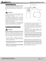
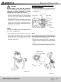
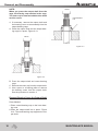
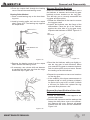
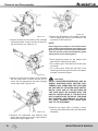
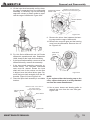
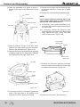
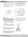
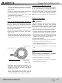
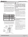
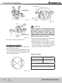
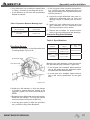
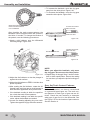
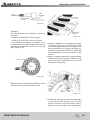
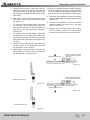
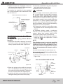
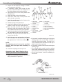
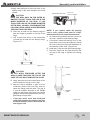
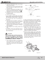
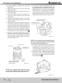
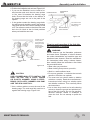
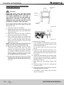
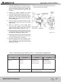
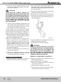
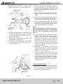
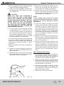
1
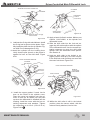
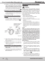
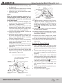
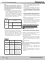
Driver-Controlled Main Differential Lock
7. Install the differential as s embl y into the
housing. See the Section 5.
8. Install and tighten the differential-to-housing
capscrews to the specified torque.
9. Install the right- and left-hand axle shafts
See the Section 5.
10.Remove the air line coupling from the main
differential actuator assembly.
11.Clean the plug, gasket, cylinder cover and
threaded service position hole in the center
of the fixed capscrew DCDL cylinder cover,
or in the center of the Threaded DCDL.
12.Tighten the plug to 44-55 lb-ft (60-75 N m).
Tighten the manual engaging capscrew to
22-28 lb-ft (30-38 N m) for fixed capscrew
DCDL style cylinders and to 7-11 lb-ft (1015 N m) for Threaded DCDL type reverse
shifters.
13.Connect the vehicle air line to the differential lock actuator assembly.
14.Install the electrical connection onto the
sensor switch located in the differential, below the actuator assembly.
15.Remove the jackstand from under the drive
axle. Lower the vehicle to the floor.
16.Fill the axle with lubricant. See the Section 7.
17.
Proceed to Check the Differential Lock
which follows.
Check the Differential Lock
1. Shift the vehicle transmission into neutral. Start
the engine to get the system air pressure to the
normal level.
WARNING
During DCDL disassembly, when the DCDL is
in the locked or engaged position and one of
the vehicle’s wheels is raised from the floor, do
not start the engine and engage the transmission. The vehicle can move and cause serious
personal injury and damage to components.
2.Place the differential lock switch in the cab
of the vehicle in the unlocked or disengaged
position.
3.Drive the vehicle at 5-10 mph (8-16 km/h)
and check the differential lock indicator light.
The light must be off when the switch is in the
unlocked or disengaged position.
98
4.Continue to drive the vehicle and place the
differential lock switch in the locked or engaged position. Let up on the accelerator to
remove the driveline torque and permit the
shift. The light must be on when the switch is
in the locked position.
• If the indicator light remains ON with the switch
in the unlocked position: The differential is still in
the locked position. Verify that the manual engaging capscrew was removed from the cylinder
cover of the DCDL shift assembly. See the the
procedure in this section.
DCDL Driver Caution Alert Label
Verify that the driver caution label is installed in
the vehicle cab. Figure 6.35. The caution label
must be placed in a location that is easily visible to the driver. The recommended location is
on the instrument panel, next to the differential
lock switch and lock indicator light.
! CUIDADO
For more information on using the lock, see the the vehicle manufacturer’s manual
• Engage DCDL only under poor road conditions.
• Do not engage DCDL during downhill operation.
• Do not engage DCDL or operate the vehicle at speeds
above 25 mph.
When DCDL is engaged, an “understeer” condition can occur
when making turns, so operate the vehicle carefully. When
you disengage DCDL, normal steering resumes.
For more information on using the lock, see the the
vehicle manufacturer’s manual.
Driver Instruction Information Available
to Orde
See the the Service Notes page on the front
inside cover of this manual to obtain the following publications.
• DCDL Caution Alert Label TP-86101;.
• DCDL Driver Instruction Kit (Contains DCDL
labeland technical bulletin) TP-9579;nico),
TP-9579;
• Traction Controls for Drive Axles DVD
T95125V.
MAINTENANCE MANUAL