1
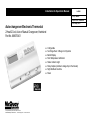
Installation & Operation Manual
Auto-changeover Electronic Thermostat
LIA266
Group: WSHP
Supercedes: LIA204-4
Date: May 2007
2 Heat/2 Cool, Auto or Manual Changeover, Hardwired
Part No. 668375401
●
●
●
●
●
●
●
●
Configurable
Two Stage Heat / 2 Stage Cool Systems
Backlit Display
Field Temperature Calibration
Status Indicator Light
Relay Outputs (minimum voltage drop in thermostat)
Night Set-Back Override
Reset
For replacement parts call 1-800-377-2787
©2008 McQuay International • www.mcquay.com • 800-432-1342
Table of Contents
Parts Diagram..............................................................................................................................1
Specifications...............................................................................................................................2
Important Safety Information......................................................................................................2
Package Contents/Tools Required................................................................................................2
To Remove Existing Thermostat.................................................................................................3
To Install Thermostat...................................................................................................................3
Remote Sensor Installation (Optional).........................................................................................5
Terminal Designator Descriptions................................................................................................6
Wiring Diagrams...........................................................................................................................6
Configuration Mode......................................................................................................................8
Testing the Thermostat.............................................................................................................11
Mode of Operation.....................................................................................................................12
Operating Modes.......................................................................................................................13
Troubleshooting.........................................................................................................................14
Factory Default Settings............................................................................................................15
Parts Diagram
S1
668375401
S2
W1 Y1 W2 Y2
O
R12
Specifications
Electrical rating: •24 VAC/VDC (18-30 VAC/VDC)
• 4 amp maximum total load
•1 amp maximum per terminal
Temperature control range: 45°F to 90°F (7°C to 32°C) Accuracy: ± 1°F (± 0.5°C)
System configurations: 2-stage heat, 2-stage cool
Timing:Backlight Operation: 13 seconds after mode change or button press
Terminations: -C, +R, W1, Y1, W2, Y2, G, O, S1, S2
Important Safety Information
WARNING!: Always turn off power at the main power supply before installing, cleaning, or removing
thermostat.
•This thermostat is for 24 VAC/VDC applications only; do not use on voltages over 30 VAC/VDC
•Do not short across terminals of system control to test operation; this will damage your thermostat and
void your warranty
•All wiring must conform to local and national electrical and building codes
•Use this thermostat only as described in this manual
Package Contents/Tools Required
Package includes:Thermostat on base, thermostat cover, wiring labels, screws and wall anchors,
Installation, Operation and Application Guide
Tools required for installation: Drill with 3/16” bit, hammer, screwdriver
To Remove Existing Thermostat
ELECTRICAL SHOCK HAZARD – Turn off power at the main service panel by removing the fuse
or switching the appropriate circuit breaker to the OFF position before removing the existing
thermostat.
1. Turn off power to the heating and cooling system by removing the fuse or switching the appropriate
circuit breaker off.
2. Remove cover of old thermostat. This should expose the wires.
3. Label the existing wires with the enclosed wire labels before removing wires.
4. After labeling wires, remove wires from wire terminals.
5. Remove existing thermostat base from wall.
6. Refer to the following section for instructions on how to install this thermostat.
To Install Thermostat
ELECTRICAL SHOCK HAZARD – Turn off power at the main service panel by removing the fuse
or switching the appropriate circuit breaker to the OFF position before removing the existing
thermostat.
IMPORTANT: Thermostat installation must conform to local and national building and electrical
codes and ordinances.
Note: Mount the thermostat about five feet above the floor. Do not mount the thermostat on an
outside wall, in direct sunlight, behind a door, or in an area affected by a vent or duct.
1. Turn off power to the heating and cooling system by removing the fuse or switching the appropriate
circuit breaker off.
To Install Thermostat (continued)
2.
To remove cover, insert and twist a coin or screwdriver in the slots on the sides of the thermostat.
3.
Put thermostat base against the wall where you plan to mount it (Be sure wires will feed through the
wire opening in the base of the thermostat).
4.
Mark the placement of the mounting holes.
5.
Set thermostat base and cover away from working area.
6.
Using a 3/16” drill bit, drill holes in the places you have marked for mounting.
7.
Use a hammer to tap supplied anchors in mounting holes.
8.
Align thermostat base with mounting holes and feed the control wires through wire opening.
9.
Use supplied screws to mount thermostat base to wall.
10. Insert stripped, labeled wires in matching wire terminals. See “Wiring Diagrams” section of this
manual (Pages 6-7).
CAUTION!: Be sure exposed portion of wires does not touch other wires.
11. Tighten screws on terminal block. Gently tug wire to be sure of proper connection. Double check that
each wire is connected to the proper terminal.
12. Seal hole for wires behind thermostat with non-flammable insulation or putty.
13. Replace cover on thermostat by snapping it in place.
14. Turn on power to the system at the main service panel.
15. Test thermostat operation as described in “Testing the Thermostat” (Page 11).
Remote Sensor Installation (Optional)
Requires McQuay Remote Sensor Part Number 667720401
1.Remove cover from remote sensor housing.
2.Select an appropriate location for mounting the remote sensor.
3.Mount remote sensor unit using hardware provided.
4.Install two strand shielded wire between remote sensor and thermostat. Shielded wire must be used.
Do not run remote sensor wire in conduit with other wires.
• Wire 1 should run between the S1 terminal on the thermostat and the S1 terminal on the
remote sensor
• Wire 2 should run between the S2 terminal on the thermostat and the S2 terminal on the
remote sensor
• Connect the shielding of the wire to the S2 terminal on the thermostat
5.Disable the main sensor (R12) on the thermostat by cutting it from the circuit board.
Terminal Designator Descriptions
-C–24 VAC/VDC common
+R–24 VAC/VDC hot
W1–1st stage heat
Y1–1st stage cool
W2–2nd stage heat
Y2–2nd stage cooling
G–Fan
O–Override
Wiring Diagrams
McQUAY SINGLE CIRCUIT
ELECTRONIC THERMOSTAT
O W G W Y F E L U A P V + 2
1 1
R C
Mark IV Board
Low Voltage Terminal Board
-C +R W1 Y1 W2 Y2
Override (Optional)
G
O
Mark IV Board Circuit 1
Low Voltage Terminal Board
O W G W Y F E L U A P V + 2
1 1
R C
Mark IV Board Circuit 2
Low Voltage Terminal Board
O W G W Y F E L U A P V + 2
1 1
R C
McQUAY DUAL CIRCUIT
-C +R W1 Y1 W2 Y2
ELECTRONIC THERMOSTAT
G
O
Override (Optional)
Configuration Mode
The configuration mode is used to set the McQuay Auto-changeover Electronic Thermostat to match your heating/cooling
system. To configure the McQuay Auto-changeover Electronic Thermostat, perform the following steps:
1. Remove the cover of the thermostat by gently pulling on one of the corners.
2. Simultaneously hold the SW5 and SW6 buttons in for 5 seconds while the McQuay Auto-changeover Electronic Thermostat
is in OFF mode.
3. Press the
or
button to change settings within each screen.
4. Press the SW6 button to advance to the next screen.
Note: The SW5 button will return you to the previous screen.
5. To exit configuration mode, slide the Mode switch to Heat or Cool.
Configuration Mode Settings
The setup screens for Configuration Mode are as follows:
1. Heat Pump and Non Heat Pump – Press the
or
button to
configure as heat pump, or non-heat pump system. Set to “O” for
all McQuay WSHP, PTAC, PTHP and UV units.
Press the SW6 button to advance to the next screen.
2. Heat Source – Set to “g”.
Press the
or
button to set to “g”.
Press the SW6 button to advance to the next screen.
SET
ROOM
REMOTE
DIFF
FILTER
SET
ROOM
REMOTE
DIFF
FILTER
3. Temperature Scale (F or C) – Choose Fahrenheit or Celsius.
Press the
or
button to select.
Press the SW6 button to advance to the next screen.
SET
ROOM
DIFF
FILTER
REMOTE
4. 1st Stage Temperature Differential (1°F to 3°F) (0.5°C to 1.5°C)
Set the number of degrees between your “setpoint” temperature
and your “turn on” temperature.
Press the
or
button to set differential value.
Press the SW6 button to advance to the next screen.
5. 2nd Stage Temperature Differential (1°F to 6°F) (0.5°C to 3.0°C)
Set the number of degrees between when stage 1 turns on
and when stage 2 turns on.
Press the
or
button to set differential value.
Press the SW6 button to advance to the next screen.
6. Minimum Deadband (2°F to 9°F) (1.0°C to 4.5°C)
Set the minimum separation between heat setpoint and
cool setpoint in Auto Changeover Mode.
Press the
or
button to set deadband.
Press the SW6 button to advance to the next screen.
7. Staged Off Outputs
Select whether the outputs for heating and cooling are staged
off independently or are satisfied simultaneously.
1 = outputs staged off independently
0 = outputs off simultaneously
Press the
or
button to set deadband.
Press the SW6 button to advance to the next screen.
8.
Minimum Cool Setpoint (45°F to 75°F) (7°C to 24.0°C)
Adjust to control the minimum Cool set temperature allowed.
Press the
or
button to select.
Press the SW6 button to advance to the next screen.
SET
ROOM
REMOTE
DIFF
FILTER
SET
ROOM
REMOTE
SET
ROOM
REMOTE
DIFF
FILTER
REMOTE
DIFF
FILTER
SET
ROOM
REMOTE
DIFF
FILTER
DIFF
FILTER
SET
ROOM
SET
ROOM
SET
ROOM
REMOTE
DIFF
FILTER
REMOTE
DIFF
FILTER
SET
ROOM
DIFF
FILTER
REMOTE
SET
ROOM
REMOTE
DIFF
FILTER
9.
Maximum Heat Setpoint (55°F to 90°F) (13°C to 32°C)
Adjust to control the maximum Heat set temperature allowed.
Press the
or
button to select.
Press the SW6 button to advance to the next screen.
SET
ROOM
DIFF
FILTER
REMOTE
SET
ROOM
DIFF
FILTER
10. Room temperature offset (+9°F to -9°F) (+4.5°C to -4.5°C)
Adjust to calibrate displayed room temperature to match actual room temperature.
Note: When not set to 0, ROOM will display
Press the
or
button to select.
Press the SW6 button to advance to the next screen.
SET
ROOM
11. Maximum compressor cycles allowed per hour (-, 2-6)
- = as many as needed, and 2-6 = maximum cycles/hour
Press the
or
button to select.
Press the SW6 button to advance to the next screen.
SET
ROOM
12. Status Indicator Light (Lt 0, 1, 2)
0 = Status indicator never on
1 = Status indicator on with first stage
2 = Status indicator on with second stage
Press the
or
button to select.
Note: Red light indicates heating cycle and green light indicates cooling cycle.
Slide the Mode switch to Heat or Cool to exit configuration.
10
REMOTE
REMOTE
DIFF
FILTER
REMOTE
DIFF
FILTER
SET
ROOM
DIFF
FILTER
REMOTE
Testing the Thermostat
Once the thermostat is installed, it should be thoroughly tested.
CAUTION!: Do not energize the air conditioning system when the outdoor temperature is below 50
degrees. It can result in equipment damage or personal injury.
Cool Test
1. Slide Mode switch to Cool mode.
2. Adjust set temperature so it is 5 degrees below room temperature.
3. Air conditioning should come on within a few seconds. Status indicator may come on.
4. Adjust the set temperature 2 degrees above the room temperature and the A/C should
turn off. There may be a fan delay on your system.
Cool Off Heat Auto
Heat Test
1. Slide Mode switch to Heat mode.
2. Adjust the set temperature so it is 5 degrees above the room temperature.
3. Heat should come on within a few seconds. Status indicator may come on.
4. Adjust the set temperature so it is 2 degrees below the room
temperature and the heat should turn off. There may be a fan delay on your system.
Cool Off Heat Auto
Fan Test
1. Slide Fan switch to On position.
2. Indoor fan turns on.
3. Slide Fan switch to Auto position.
4. Indoor fan turns off.
Auto
On
Auto
On
11
Mode of Operation
The McQuay Auto-changeover Electronic Thermostat is a two-stage heat, two-stage cool thermostat.
The thermostat activates the first stage of heating when the room temperature is below the heat set
temperature (by the differential temperature). The second stage of heating will be activated if the room
temperature continues to drop. The heat outputs are staged off (configurable, setting 7, Page 9) as the
room temperature increases.
When the room temperature is greater than the cool set temperature (by the differential temperature), the
cooling device is activated. The second stage of cooling will be activated if the room temperature continues
to rise. The cool outputs are staged off (configurable, setting 7, Page 9) as the room temperature drops.
The thermostat has the following operating modes: OFF, Heat, Cool and Auto. In OFF mode, the thermostat
will not turn on heating or cooling devices. In the Heat mode, the thermostat controls the heating system. In
the Cool mode, the thermostat controls the cooling system. In the Auto mode, the thermostat operates as
an auto-changeover thermostat. It will turn on heating or cooling as required. The indoor fan can be turned
on in all operating modes using the Fan switch.
Pressing the
and
buttons simultaneously for 2 seconds causes the thermostat to output from the “O” terminal for 5 seconds. “ ” will show on the display. This will result in the unit going into a night setback override.
Pressing the
and
buttons simultaneously for 10 seconds causes the thermostat to output from the “O”
terminal for 15 seconds. “ ” will show on the display. This will result in the unit being reset.
12
Operating Modes
These are the possible operating modes of the McQuay Auto-changeover Electronic Thermostat.
Off Mode
In off mode, the thermostat will not turn on the heating or cooling appliances.
Note 1:The indoor fan can be activated in every mode by sliding the Auto/On fan switch to the On position.
Note 2:Off mode is used to enter the configuration setup (by pressing SW5 and SW6 simultaneously for 5 seconds).
Cool Mode
In cool mode, the thermostat controls the cooling system.
Heat Mode
In heat mode, the thermostat controls the heating system.
Auto-changeover Mode
In this mode the thermostat will automatically change from heat mode to cool mode, or vice versa.
Pressing the
or
button in Auto mode causes the thermostat to display the heat set temperature then the
cool set temperature. The set temperature that is displayed can be changed using the the
or
buttons.
Override
Press
and
displayed.
buttons simultaneously for 2 seconds to override night setback. When override is activated, “ ” will be
Reset
Press
and
buttons simultaneously for 10 seconds to reset the control board. “ ” will be displayed.
13
Troubleshooting
Symptom
Remedy
No display
Check for 24 VAC/VDC at thermostat; display is blank when 24 VAC/VDC is not present
System fan does not come
on properly
Verify wiring is correct
Check configuration (see “Configuration Mode,” Setting 2, Page 8)
See “Fan Test” (Page 11)
Thermostat turns on and
off too frequently
Adjust temperature differential (see “Temperature Differential,” “Configuration Mode,”
Settings 4 and 5, Page 9)
Fan runs continuously
Check fan On/Auto switch, ON position runs indoor fan continuously
Room temperature is not
correct
Verify wall hole is plugged with putty or insulation; calibrate thermostat (see
“Configuration Mode,” Setting 10, Page 10)
ROOM displays
Room temperature offset is not zero (see “Configuration Mode,” Setting 10, Page 10)
Status indicator
Green light – Cooling operation
Red light – Heating operating
Status indicator option ON (see “Configuration Mode,” Setting 12, Page 10)
Er displays
Sensor error – check S1 & S2 connections, check remote sensor wire and connections,
use shielded wire for remote sensor
Problem not listed above
Press the Reset button once; display will be refreshed and anti-short cycle timing will be
reset to zero
14
McQuay Auto-changeover Electronic Thermostat
Factory Default Settings
Note:
Following are the factory default settings for the McQuay 2811 thermostat:
1.
Heat pump
0
2.
HS gE
g
3.
FC
F
4.
Differential 01
1
5.
Differential 02
2
6.
db
4
7.
Staged outputs
8.
LO
45
9.
UP
90
1
10.
Calibration
11.
Maximum compressor cycles per hour
0
-
12.
Lt
1
15
This page left intentionally blank.
This page left intentionally blank.
McQuay Training and Development
Now that you have made an investment in modern, efficient McQuay equipment, its care should be a high priority.
For training information on all McQuay HVAC products, please visit us at www.mcquay.com and click on training, or call 540-248-9646 and ask for the Training
Department.
Warranty
All McQuay equipment is sold pursuant to its standard terms and conditions of sale, including Limited
Product Warranty. Consult your local McQuay Representative for warranty details. Refer to Form
933-43285Y. To find your local McQuay Representative, go to www.mcquay.com.
This document contains the most current product information as of this printing. For the most up-to-date product information, please go to www.
mcquay.com.
For replacement parts call 1-800-377-2787
©2008 McQuay International
(800) 432-1342
www.mcquay.com LIA266 / Version A: 5-18-07