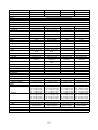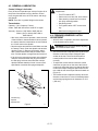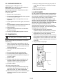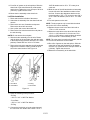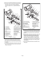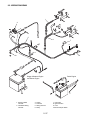
1
Professional 2-Wheel Tractor
Service Manual
Models 985103,104, 105, 107 - 115, 117
08483800 08/00
Printed in USA
TABLE OF CONTENTS
Section 1 - Introduction . . . . . . . . . . . . . . . . . . . 1-3
1.1 The Manual. . . . . . . . . . . . . . . . . . . . . . . . . 1-3
Section 6 - Steering & Controls . . . . . . . . . . . 6-18
6.1 Handlebar Assembly. . . . . . . . . . . . . . . . . 6-18
1.2 Service And Replacement Parts . . . . . . . . . 1-3
6.2 Steering Brakes (Optional) . . . . . . . . . . . . 6-19
1.3 Product Registration . . . . . . . . . . . . . . . . . . 1-3
6.3 Adjusting Brakes . . . . . . . . . . . . . . . . . . . . 6-19
1.4 Unauthorized Replacement Parts . . . . . . . . 1-3
6.4 Power Take Off Control. . . . . . . . . . . . . . . 6-22
1.5 Disclaimer . . . . . . . . . . . . . . . . . . . . . . . . . . 1-3
6.5 Range Shift Control (Two Speed Axle) . . . 6-22
Section 7 - Drive Train . . . . . . . . . . . . . . . . . . . 7-23
7.1 Transmission Trouble Analysis . . . . . . . . . 7-23
1.6 Technical Service Communications . . . . . . 1-3
1.7 Preparation . . . . . . . . . . . . . . . . . . . . . . . . . 1-4
Section 2 - Safety . . . . . . . . . . . . . . . . . . . . . . . . 2-4
2.1 Safety Alerts . . . . . . . . . . . . . . . . . . . . . . . . 2-4
7.2 Clutch Adjustment. . . . . . . . . . . . . . . . . . . 7-24
7.3 Transmission Removal . . . . . . . . . . . . . . . 7-24
2.3 Notations. . . . . . . . . . . . . . . . . . . . . . . . . . . 2-4
7.4 Forward-Reverse Clutch &
Planetary System . . . . . . . . . . . . . . . . . . . 7-24
2.4 Practices And Laws . . . . . . . . . . . . . . . . . . 2-4
7.5 First -Second Gear, Clutch And Planetary 7-24
2.5 Maintenance And Storage . . . . . . . . . . . . . 2-4
7.6 Differential. . . . . . . . . . . . . . . . . . . . . . . . . 7-25
2.6 Safety Rules . . . . . . . . . . . . . . . . . . . . . . . . 2-4
7.7 Differential Removal . . . . . . . . . . . . . . . . . 7-25
2.7 Training . . . . . . . . . . . . . . . . . . . . . . . . . . . . 2-4
7.8 Power Take Off (PTO). . . . . . . . . . . . . . . . 7-28
Section 8 - Fuel System. . . . . . . . . . . . . . . . . . 8-29
8.1 Fuel System Troubleshooting . . . . . . . . . . 8-29
2.2 Signal Words. . . . . . . . . . . . . . . . . . . . . . . . 2-4
2.8 Preparation . . . . . . . . . . . . . . . . . . . . . . . . . 2-5
2.9 Operation . . . . . . . . . . . . . . . . . . . . . . . . . . 2-5
Section 3 - Specifications . . . . . . . . . . . . . . . . . 3-6
8.2 Fuel Pump . . . . . . . . . . . . . . . . . . . . . . . . 8-30
8.3 Fuel System Contamination . . . . . . . . . . . 8-30
Section 4 - General Maintenance
& Adjustments . . . . . . . . . . . . . . . . . . . . . . 4-10
4.1 Controls And Features . . . . . . . . . . . . . . . 4-10
8.4 Fuel Tank . . . . . . . . . . . . . . . . . . . . . . . . . 8-30
Section 9 - Electrical . . . . . . . . . . . . . . . . . . . . 9-31
9.1 Tools . . . . . . . . . . . . . . . . . . . . . . . . . . . . . 9-31
4.2 Filling The Fuel Tank. . . . . . . . . . . . . . . . . 4-10
9.2 Electrical Measurements. . . . . . . . . . . . . . 9-31
4.3 General Lubrication . . . . . . . . . . . . . . . . . 4-11
9.3 Safety Interlock System . . . . . . . . . . . . . . 9-32
4.4 Forward-Reverse Clutch Adjustment . . . . 4-11
9.4 Battery . . . . . . . . . . . . . . . . . . . . . . . . . . . 9-32
4.5 Hi/Low Gear Clutch Adjustment . . . . . . . . 4-12
9.5 Switches . . . . . . . . . . . . . . . . . . . . . . . . . . 9-35
4.6 Steering Brake Adjustment
(Applicable Models) . . . . . . . . . . . . . . . . . 4-12
9.6 Solenoid And Relays. . . . . . . . . . . . . . . . . 9-35
4.7 PTO Brake Adjustment . . . . . . . . . . . . . . . 4-13
9.7 Fuses . . . . . . . . . . . . . . . . . . . . . . . . . . . . 9-36
4.8 Slip Clutch Adjustment . . . . . . . . . . . . . . . 4-14
Section 5 - Engine . . . . . . . . . . . . . . . . . . . . . . 5-15
5.1 Engine Troubleshooting . . . . . . . . . . . . . . 5-15
9.8 Diodes And Rectifiers . . . . . . . . . . . . . . . . 9-36
5.2 Checking Engine Oil . . . . . . . . . . . . . . . . . 5-16
9.11 12 HP Electric Start - Kohler . . . . . . . . . . 9-39
5.3 Changing Oil . . . . . . . . . . . . . . . . . . . . . . . 5-16
9.12 8 HP Manual Start - Kohler . . . . . . . . . . . 9-40
5.4 Air Cleaner . . . . . . . . . . . . . . . . . . . . . . . . 5-16
9.13 8 HP Electric Start - Kohler . . . . . . . . . . . 9-41
5.5 Engine Removal And Installation . . . . . . . 5-17
9.14 16 HP Electric Start - Briggs . . . . . . . . . . 9-42
5.6 Engine Maintenance . . . . . . . . . . . . . . . . . 5-17
9.15 Robin Engines . . . . . . . . . . . . . . . . . . . . 9-43
9.9 Wiring Diagram . . . . . . . . . . . . . . . . . . . . . 9-37
9.10 Continuity Diagram . . . . . . . . . . . . . . . . . 9-38
5.7 Engine Storage . . . . . . . . . . . . . . . . . . . . . 5-17
2
SECTION 1 - INTRODUCTION
1.1 THE MANUAL
1.4 UNAUTHORIZED REPLACEMENT
PARTS
The purpose of this manual is to provide complete
instructions for service, maintenance, disassembly,
repair, and installation of the mechanical components
for the unit.
Use only Gravely replacement parts. The replacement
of any part on this vehicle with anything other than a
Gravely authorized replacement part may adversely
affect the performance, durability, or safety of this unit
and may void the warranty. Gravely disclaims liability
for any claims or damages, whether warranty, property
damage, personal injury, or death arising out of the use
of unauthorized replacement parts.
Dealer trained service personnel should use this
manual as a supplement to and reminder of the training
sessions conducted by the company.
Read all information for servicing a part or system
before repair work is started to avoid needless
disassembly.
1.5 DISCLAIMER
Operation
Gravely reserves the right to discontinue, make
changes to, and add improvements upon its products
at any time without public notice or obligation. The
descriptions and specifications contained in this
manual were in effect at printing. Equipment described
within this manual may be optional. Some illustrations
may not be applicable to your unit.
Before operation of the unit, carefully and completely
read manuals supplied with the unit. The contents will
provide you with an understanding of safety
instructions and controls during normal operation and
maintenance.
Safety Messages
For your safety and the safety of others always read,
understand, and follow all DANGER, WARNING, and
CAUTION messages found in manuals and on safety
decals.
1.6 TECHNICAL SERVICE
COMMUNICATIONS
Directional Reference
All reference to left, right, front, or rear are given from
the operator in the operator position and facing the
direction of forward travel.
1.2 SERVICE AND REPLACEMENT PARTS
When ordering publications, replacement parts, or
making service inquiries, know the Model and Serial
numbers of your unit and engine.
Numbers are located on the product registration form in
the unit literature package. They are printed on a serial
number label, located under the hood of your unit.
1.3 PRODUCT REGISTRATION
A warranty registration card must be filled out, signed,
and returned at time of purchase. This card activates
the warranty. Claims meeting requirements during
limited warranty period will be honored.
Gravely Technical Service communicates information
to the field using Service Letters, Service Bulletins,
Product Notices, and Campaigns. Each
communication signifies a type of information and
priority. The dealer is responsible to carry out the
directive provided in the communication. The types of
communication are:
Service Letter - General technical information for the
dealer. Technical information on how to service the
product and product improvements.
Service Bulletin - Notification to update products to
resolve certain issues or a notification of a policy
change.
Product Notices - Notification of limited product
located in a certain region. This is a limited distribution
to only those who received the product involved.
Campaigns - Notification of a safety related issue. All
products must be updated and are tracked by the
factory until all units are corrected.
Specific Model and Serial Numbers are on a label
located on the frame of your Tractor and on a label
located on the product registration form. Record those
numbers below and transfer the label from the product
registration to place indicated below. Use these
numbers whenever parts or service is required.
1 -3
1.7 PREPARATION
Before starting any removal of parts, proper
preparation is very important for efficient work. A clean
work area at the start of each job will allow you to
perform service repairs easily and quickly.
in the disassembly order on a clean work surface.
Organization is a key part of proper reassembly.
Tools, instruments, and parts needed for the job should
be gathered before work is started. Interrupting a job to
locate tools or parts is a needless delay.
To reduce the incidence of misplaced tools or parts,
place removed components with all attaching hardware
SECTION 2 - SAFETY
2.1 SAFETY ALERTS
Look for these symbols to point out
important safety precautions. They
mean:
Attention!
Personal Safety Is Involved!
Become Alert!
Obey The Message!
2.2 SIGNAL WORDS
The safety alert symbol is used in decals on the unit
and with proper operation procedures in this manual.
They alert you to the existence and relative degree of
hazards.
Understand the safety message. It contains important
information about personal safety on or near the unit.
DANGER: IMMINENTLY HAZARDOUS
SITUATION! If not avoided, WILL RESULT in
death or serious injury.
WARNING: POTENTIALLY HAZARDOUS
SITUATION! If not avoided, COULD RESULT
in death or serious injury.
unsafe conditions and the possibility of minor,
moderate, or serious injury or death. Learn applicable
rules and laws in your area.
2.5 MAINTENANCE AND STORAGE
Keep the equipment in good condition. Maintain it as
directed in this manual. Check all hardware at regular
intervals.
Use only Gravely accessories, attachment and
replacement parts.
Do not overspeed the engine. Do not override the
governor.
Before making any repairs, adjustments inspections or
cleaning unit disengage the PTO, turn off and remove
the ignition key and wait for all motion to stop.
To reduce fire hazard and overheating, keep
equipment free of grass, leaves, debris or excessive
lubricants.
Worn out mufflers can result in fire or explosion and
should be replaced immediately.
Never store equipment with gasoline in tank inside a
building where fumes may reach an open flame or
spark. Allow engine to cool before storing in any
enclosure.
2.6 SAFETY RULES
CAUTION: POTENTIALLY HAZARDOUS
SITUATION! If not avoided, MAY RESULT in
minor or moderate injury. It may also be used
to alert against unsafe practices.
2.3 NOTATIONS
NOTE: General reference information for proper operation and maintenance practices.
IMPORTANT: Specific procedures or information
required to prevent damage to unit or attachment.
2.4 PRACTICES AND LAWS
Practice usual and customary safe working
precautions, for the benefit of yourself and others.
Understand and follow all safety messages. Be alert to
Improper use of this tractor can injure people and
damage the equipment. People using or servicing this
tractor must read and follow the instructions in this
manual.
It is important to understand that this manual and any
other Gravely instruction manuals do not cover every
possible danger. It is impossible for Gravely to know of
all possible dangers in operating and servicing the
tractor and attachments.
The purchaser must give these instructions to the
people operating and maintaining this tractor. These
people must use eye and foot protection.
2.7 TRAINING
Read this manual, the attachment manual and the
engine manual carefully before operating unit.
2 -4
Learn the location and function of all controls.
Learn how to use the controls to stop the wheels and
attachment quickly in an emergency.
Understand and follow each danger, warning, caution
and instruction decal installed on this product.
Never permit children to operate the Two-Wheel
Tractor. Do not allow adults to operate it without proper
instruction. Safe operation of this equipment requires
your complete and unimpaired attention at all times. Do
not operate unit after or during the consumption of
drugs or alcohol.
Keep all people and animals away from the operating
area.
2.8 PREPARATION
Use caution with gasoline. Gasoline is very flammable
and its vapors are explosive. Keep it in a clean, tight
and approved (Red) container. Never put gasoline in
the fuel tank while the engine is running or hot. Clean
up spilled gasoline before starting engine. Do not fill
fuel tank indoors. Never allow smoking materials,
sparks or flame (match, pilot light, etc.) near mower or
fuel container. Replace fuel tank cap and fuel container
cap securely.
Inspect area of operation and remove all material
which could be thrown by the attachment such as
stones, sticks, wires and other foreign objects.
When hauling the equipment, connect the chassis to
the transporting vehicle. Never connect from control
levers, rods, or like items that could be damaged.
Replace all parts that become damaged or lost.
Wear hand, foot, head, ear and eye protection. Do not
wear loose clothing, which might get caught in rotating
parts of the unit.
Before making adjustments, cleaning, removing
obstructions or servicing the tractor or attachment
move the PTO to "OFF", turn the ignition switch to
"OFF", remove the ignition key and wait until all moving
parts completely stop.
WARNING: Always block wheels and know
that jack stands or blocks used are stable,
strong, or secure and will hold the weight of
the unit during maintenance.
only if at least one of the operator presence switches is
depressed.
Do not use the equipment in the dark without adequate
lighting.
Keep away from moving parts. Stay clear of the
attachment whenever the engine is running.
Do not let people other than the operator near the
operating equipment. Never direct disengage the
attachment drive when moving the tractor to and from
work areas.
Use a slow speed and engage the shift lever slowly
when operating on slopes.
Travel across slopes, not up and down. Use extreme
caution when changing direction on slopes. Do not
operate on steep slopes.
Look for and keep away from hazards, such as
dropoffs. Stay alert for holes, rocks and other hidden
hazards in the area of operation.
After hitting an object, disengage the PTO, turn off and
remove the ignition key and wait for all motion to stop.
Check for damage. Repair any damage before
restarting unit.
Look behind when operating in reverse. Look for
people and hazards.
Operate only from the operator’s position, just behind
the handlebars.
If there is a sudden change in the sound or vibration of
the equipment, disengage the PTO, turn off and
remove the ignition key, wait for all motion to stop and
check for damage. Repair any damage or failure before
restarting unit.
Never run the engine indoors except to move it outside.
Exhaust fumes are dangerous.
Go slowly on slick surfaces. Always be sure of your
footing, keep a firm grip on the handlebars and walk,
never run.
Follow traffic laws when operating on or near a road.
Before leaving the operator’s position, put the PTO
lever in the "OFF" position, turn off and remove ignition
key. Move the shift control to first gear position.
Do not touch parts which might be hot from operation.
Before attempting to maintain, adjust or service allow
such parts to cool.
2.9 OPERATION
Be certain that all shields, guards, and interlock
switches are in the correct position and operating
properly.
Before starting the engine, put the PTO lever in the
"OFF" position and the gear shift lever in the neutral
"N" position.
Check the operation of the operator presence controls
before operating the tractor. With either the PTO or the
direction control lever engaged, the engine should run
2 -5
SECTION 3 - SPECIFICATIONS
Model Number
Description
985103
8HP Gear Drive
Brakes
985104
985105
985107
8HP Gear Drive
8HP Gear Drive
12 HP Gear Drive
Optional, individual, 7" (17.8 cm) x 1.75" (4.4 cm) drum type
Steering
Manual, optional power steering kit available
Turning Radius
Minimum Uncut Circle
Zero (with steering kit)
Zero
Zero
Zero
Zero
4" x 8", 4 ply
Optional Tire Sizes
-Stud Tread
4" x 8", 4 ply
4" x 8", 4 ply
4" x 8", 4 ply
-Trac Tread
4" x 8", 4 ply
4" x 8", 4 ply
4" x 8", 4 ply
4" x 8", 4 ply
-Turf-Chief
18" x 6.5" x 8", 4 ply
18" x 6.5" x 8", 4 ply
18" x 6.5" x 8", 4 ply
18" x 6.5" x 8", 4 ply
-Turf-Saver
18" x 8.5" x 8", 4 ply
18" x 8.5" x 8", 4 ply
18" x 8.5" x 8", 4 ply
18" x 8.5" x 8", 4 ply
16" x 5" x 3", 4 ply
16" x 5" x 3", 4 ply
16" x 5" x 3", 4 ply
16" x 5" x 3", 4 ply
18 psi
18 psi
18 psi
18 psi
Battery
12 volt, BCI group
12 volt, BCI group
12 volt, BCI group
12 volt, BCI group
Engine
Kohler
Kohler
Kohler
Kohler
K181T
K181T
K181S
M12T (PS471525)
8HP at 3600 RPM
8HP at 3600 RPM
8HP at 3600 RPM
12HP at 3600 RPM
One
One
One
One
18 cu. in. (305.4 cc)
18 cu. in. (305.4 cc)
18 cu. in. (305.4 cc)
29 cu. in. (476.5 cc)
Gasoline, 87 minimum
octane
Gasoline, 87 minimum
octane
Gasoline, 87 minimum
octane
Gasoline, 87 minimum
octane
2.0 gals. (4.7 L)
-Semi-Pneumatic
Tire Pressure
-Type
-Horsepower
-Number of Cylinders
-Displacement
-Fuel
-Fuel Capacity
1.25 gals. (4.7 L)
1.25 gals. 4.7 L)
1.25 gals. (4.7 L)
-Cooling
Air
Air
Air
Air
-Air Filter
Dual Element with
PreCleaner
Dual Element with
PreCleaner
Dual Element with
PreCleaner
Dual Element with
PreCleaner
-Lubrication
-Oil Type
-Oil Capacity
-Oil Filter
-Charging System
Splash System
Splash System
Splash System
Splash System
See Engine Manual
See Engine Manual
See Engine Manual
See Engine Manual
2.5 pts. (1.2 L)
2.5 pts. (1.2 L)
2.5 pts. (1.2 L)
2.5 pts. (1.2 L)
N/A
N/A
N/A
Spin on oil filter
Recoil
Recoil
12 volt, 15 amp
12 volt, 15 amp
Transmission
-Type
All gear planetary transmission with fully enclosed PTO and immersion clutch
-Oil Type
-Oil Capacity
-Cooling
-Number of Speeds
SAE 30W API service class SF or higher
5 qts (4.7 L)
5 qts (4.7 L)
5 qts (4.7 L)
Air
Air
Air
5 qts (4.7 L)
Air
2 forward/2 reverse
4 forward/4 reverse
4 forward/4 reverse
4 forward/4 reverse
Speeds (with 18" tires)
-Forward
1st - 2.0 mph (3.2 kph)
2nd - 2.5 mph (4.0 kph)
1st - 1.3 mph (2.1 kph)
2nd - 1.7 mph (2.7 kph)
3rd - 2.6 mph (4.2 kph)
4th - 3.4 mph (5.5 kph)
1st - 1.4 mph (2.3 kph)
2nd - 1.8 mph (2.9 kph)
3rd - 2.7 mph (4.4 kph)
4th - 3.7 mph (6.0 kph)
-Reverse
1st - 1.9 mph (3.1 kph)
2nd - 2.4 mph (3.9 kph)
1st - 1.2 mph (2.0 kph
2nd - 1.6 mph (2.6 kph)
3rd - 2.4 mph (3.9 kph)
4th - 3.1 mph (5.0 kph)
1st - 1.3 mph (2.1 kph)
2nd - 1.7 mph (2.7 kph)
3rd - 2.6 mph (4.2 kph)
4th - 3.3 mph (5.3 kph)
PTO
-Type
-Drive
-Output Speeds
Construction
Internal Slip Clutch
Internal Slip Clutch
Internal Slip Clutch
All gear shaft driven off high/low planetary
High - 1179 RPM, low - 888 RPM at 3300 engine RPM
Cast-iron transmission case with 7-gauge framing
3 -6
Internal Slip Clutch
Model Number
Description
985108
12HP Gear Drive
Brakes
985109
985110
985111
16HP Gear Drive
8HP Gear Drive
8HP Gear Drive
Optional, individual, 7" (17.8 cm) x 1.75 (4.4 cm) drum type
Steering
Manual, optional power steering kit available
Turning Radius
Zero (with steering kit)
Minimum Uncut Circle
Zero
Optional Tire Sizes
-Stud Tread
4" x 8", 4 ply
4" x 8", 4 ply
4" x 8", 4 ply
-Trac Tread
4" x 8", 4 ply
4" x 8", 4 ply
4" x 8", 4 ply
4" x 8", 4 ply
-Turf-Chief
18" x 6.5" x 8", 4 ply
18" x 6.5" x 8", 4 ply
18" x 6.5" x 8", 4 ply
18" x 6.5" x 8", 4 ply
-Turf-Saver
18" x 8.5" x 8", 4 ply
18" x 8.5" x 8", 4 ply
18" x 8.5" x 8", 4 ply
18" x 8.5" x 8", 4 ply
16" x 5" x 3", 4 ply
16" x 5" x 3", 4 ply
16" x 5" x 3", 4 ply
16" x 5" x 3", 4 ply
18 psi
18 psi
18 psi
18 psi
12 volt, BCI group
12 volt, BCI group
None
12 volt, BCI group
-Semi-Pneumatic
Tire Pressure
Battery
Engine
4" x 8", 4 ply
Kohler
Briggs & Stratton
Kohler
Kohler
-Type
M12S (PS471529)
303447
PS-301058
PS-30159
-Horsepower
12HP at 3600 RPM
16 HP at 3600 RPM
8 HP at 3600 RPM
8 HP at 3600 RPM
One
Two
One
One
29 cu. in. (477 cc)
29.3 cu. in. (480 cc)
18 cu. in. (305.4 cc)
18 cu. in. (305.4 cc)
Gasoline, 87 minimum
octane
Gasoline, 87 minimum
octane
See Engine Manual
See Engine Manual
1.25 gals. (4.7 L)
-Number of Cylinders
-Displacement
-Fuel
-Fuel Capacity
2.0 gals. (7.5 L)
1.5 gals. (5.7 L)
1.25 gals. (4.7 L)
-Cooling
Air
Air
Air
Air
-Air Filter
Dual Element with
PreCleaner
Dual Element with
PreCleaner
Dual Element with
PreCleaner
Dual Element with
PreCleaner
Splash System
Full pressure pump with
oil filter
Splash System
Splash System
See Engine Manual
-Lubrication
See Engine Manual
See Engine Manual
See Engine Manual
-Oil Capacity
-Oil Type
2.5 pts. (1.2 L)
3.0 pts. (1.4 L)
2.5 pts. (1.2 L)
2.5 pts. (1.2 L)
-Oil Filter
Spin on oil filter
Spin on oil filter
Spin on oil filter
Spin on oil filter
-Charging System
12 volt, 15 amp
12 volt, 16 amp
Recoil
12 volt, 15 amp
Transmission
-Type
All gear planetary transmission with fully enclosed PTO and immersion clutch
-Oil Type
-Oil Capacity
SAE 30W API service class SF or higher
5 qts (4.7 L)
5 qts (4.7 L)
5 qts (4.7 L)
Air
Air
Air
Air
2 forward/2 reverse
4 forward/4 reverse
4 forward/4 reverse
4 forward/4 reverse
-Forward
1st - 1.4 mph (2.3 kph)
2nd - 1.8 mph (2.9 kph)
3rd - 2.7 mph (4.4 kph)
4th - 3.7 mph (6.0 kph)
1st - 1.4 mph (2.3 kph)
2nd - 1.8 mph (2.9 kph)
3rd - 2.7 mph (4.4 kph)
4th - 3.7 mph (6.0 kph)
1st - 1.4 mph (2.3 kph)
2nd - 1.8 mph (2.9 kph)
3rd - 2.7 mph (4.4 kph)
4th - 3.7 mph (6.0 kph)
1st - 1.4 mph (2.3 kph)
2nd - 1.8 mph (2.9 kph)
3rd - 2.7 mph (4.4 kph)
4th - 3.7 mph (6.0 kph)
-Reverse
1st - 1.3 mph (2.1 kph)
2nd - 1.7 mph (2.7 kph)
3rd - 2.6 mph (4.2 kph)
4th - 3.3 mph (5.3 kph)
1st - 1.3 mph (2.1 kph)
2nd - 1.7 mph (2.7 kph)
3rd - 2.6 mph (4.2 kph)
4th - 3.3 mph (5.3 kph)
1st - 1.3 mph (2.1 kph)
2nd - 1.7 mph (2.7 kph)
3rd - 2.6 mph (4.2 kph)
4th - 3.3 mph (5.3 kph)
1st - 1.3 mph (2.1 kph)
2nd - 1.7 mph (2.7 kph)
3rd - 2.6 mph (4.2 kph)
4th - 3.3 mph (5.3 kph)
-Cooling
-Number of Speeds
5 qts (4.7 L)
Speeds
PTO
-Type
Internal Slip Clutch
Internal Slip Clutch
Internal Slip Clutch
Internal Slip Clutch
-Drive
All gear shaft driven off
high/low planetary
All gear shaft driven off
high/low planetary
All gear shaft driven off
high/low planetary
All gear shaft driven off
high/low planetary
Output Speeds
Construction
High - 1179 RPM, low - 888 RPM at 3300 engine RPM
Cast-iron transmission case with 7-gauge framing
3 -7
Model Number
Description
985112
985113
985114
985115
12 HP
12 HP
16 HP
8.5 HP
Gear Drive
Gear Drive
Gear Drive
Gear Drive
7 x 1.75" Drum Type
N/A
Brakes
Steering
Manual, optional power steering kit available
Turning Radius
Zero (with steering kit)
Minimum Uncut Circle
Zero
Optional Tire Sizes
-Stud Tread
4.00-8
4.00-8
4.00-8
-Trac Tread
4.00-8
4.00-8
4.00-8
4.00-8
-Turf-Chief
18" x 6.50"-8"
18" x 6.50"-8"
18" x 6.50"-8"
18" x 6.50"-8"
-Turf-Saver
18" x 8.50"-8"
18" x 8.50"-8"
18" x 8.50"-8"
18" x 8.50"-8"
N/A
N/A
16" x 5" x 3"
16" x 5" x 3"
18 psi (124 Kn/m2)
18 psi (124 Kn/m2)
See Tire Sidewall
See Tire Sidewall
Battery
12V BCI Group
12V BCI Group
12V BCI Group
12V BCI Group
Engine
Kohler
Kohler
Briggs & Stratton
Robin
PS-471529
PS-471529
303447
EH252-0225T
12 HP
12 HP
16 HP
8.5 HP
One
One
Two
One
29.3 cu. in. (480 cc)
15.31 cu. in. (251 cc)
-Semi-Pneumatic
Tire Pressure
-Type
-Horsepower
-Number of Cylinders
-Displacement
-Fuel
-Fuel Capacity
4.00-8
See Engine Manual
See Engine Manual
Auto Gasoline
Auto Gasoline
2.0 gals. (7.5 L)
2.0 gals. (7.5 L)
1.5 gals. (5.7 L)
1.5 gals. (5.7 L)
-Cooling
Air
Air
Air
Air
-Air Filter
Dual Element with
PreCleaner
Dual Element with
PreCleaner
Dual Element with
PreCleaner
Dual Element with
PreCleaner
-Lubrication
-Oil Type
Splash Type
Splash Type
Pump w/oil filter
Splash Type
See Engine Manual
See Engine Manual
See Engine Manual
SAE 20#, 30# 10W-30
-Oil Capacity
2.5 pts. (1.2 L)
2.5 pts. (1.2 L)
3.0 pts. (1.4 L)
2.1 pts. (1.0 L)
-Oil Filter
Spin on oil filter
Spin on oil filter
Spin on oil filter
Spin on oil filter
-Charging System
12 volt, 15 amp
12 volt, 15 amp
12 volt, 16 amp
13 volt, 11.5 amp
Transmission
-Type
All gear transmission w/fully enclosed PTO and immersion clutch
-Oil Type
-Oil Capacity
SAE 30W API service class SF or higher
5 qts. (4.7 L)
5 qts. (4.7 L)
5 qts. (4.7 L)
Air
Air
Air
Air
4 forward/4 reverse
4 forward/4 reverse
4 forward/4 reverse
4 forward/4 reverse
-Forward
1st - 1.4 mph (2.3 kph)
2nd - 1.8 mph (2.9 kph)
3rd - 2.7 mph (4.4 kph)
4th - 3.7 mph (6.0 kph)
1st - 1.4 mph (2.3 kph)
2nd - 1.8 mph (2.9 kph)
3rd - 2.7 mph (4.4 kph)
4th - 3.7 mph (6.0 kph)
1st - 1.4 mph (2.3 kph)
2nd - 1.8 mph (2.9 kph)
3rd - 2.7 mph (4.4 kph)
4th - 3.7 mph (6.0 kph)
1st - 1.3 mph (2.1 kph)
2nd - 1.7 mph (2.7 kph)
3rd - 2.6 mph (4.2 kph)
4th - 3.4 mph (5.5 kph)
-Reverse
1st - 1.3 mph (2.1 kph)
2nd - 1.7 mph (2.7 kph)
3rd - 2.6 mph (4.2 kph)
4th - 3.3 mph (5.3 kph)
1st - 1.3 mph (2.1 kph)
2nd - 1.7 mph (2.7 kph)
3rd - 2.6 mph (4.2 kph)
4th - 3.3 mph (5.3 kph)
1st - 1.3 mph (2.1 kph)
2nd - 1.7 mph (2.7 kph)
3rd - 2.6 mph (4.2 kph)
4th - 3.3 mph (5.3 kph)
1st - 1.3 mph (2.1 kph)
2nd - 1.7 mph (2.7 kph)
3rd - 2.6 mph (4.2 kph)
4th - 3.3 mph (5.3 kph)
-Cooling
-Number of Speeds
5 qts. (4.7 L)
-Direction Control
Speeds (with 18" tires)
(with 14" tires)
PTO
-Type
Internal Slip Clutch
Internal Slip Clutch
Internal Slip Clutch
Internal Slip Clutch
-Drive
All gear shaft driven off
high/low planetary
All gear shaft driven off
high/low planetary
All gear shaft driven off
high/low planetary
All gear shaft driven off
high/low planetary
-Output Speeds
Construction
High - 1179 RPM, low - 888 RPM at 3300 engine RPM
Cast-iron transmission case with 7-gauge framing
3 -8
Model Number
985117
Description
13.5 HP Gear Drive
Brakes
7 x 1.75" Drum Type
Steering
Manual, optional power
steering kit available
Turning Radius
Zero (with steering kit)
Minimum Uncut Circle
Zero
Optional Tire Sizes
-Stud Tread
4.00"-8"
-Trac Tread
4.00"-8"
-Turf-Chief
18" x 6.50"-8"
-Turf-Saver
18" x 8.50"-8"
-Semi-Pneumatic
Tire Pressure
Battery
Engine
-Type
-Horsepower
-Number of Cylinders
-Displacement
16" x 5" x 3"
See Tire Sidewall
12V BCI Group
Robin
EH410-0226T
13.5 HP
One
24.67 cu. in. (440 cc)
-Fuel
Auto gasoline
-Fuel Capacity
1.5 gal. (5.7 L)
-Cooling
Air
-Air Filter
Dual element
-Lubrication
-Oil Type
-Oil Capacity
-Oil Filter
-Charging System
Splash Type
See Engine Manual
5 qts. (4.7 L)
Spin on filter
12 volt, 12.5 amp
Transmission
-Type
-Oil Type
-Oil Capacity
-Cooling
-Number of Speeds
Gear transmission
SAE 30W API service
class SF or higher
5 qts. (4.7 L)
Air
4 forward/4 reverse
-Direction Control
Speeds (with 18" tires)
-Forward
1st - 1.4 mph (2.3 kph)
2nd - 1.8 mph (2.9 kph)
3rd - 2.7 mph (4.4 kph)
4th - 3.7 mph (6.0 kph)
-Reverse
1st - 1.3 mph (2.1 kph)
2nd - 1.7 mph (2.7 kph)
3rd - 2.6 mph (4.2 kph)
4th - 3.3 mph (5.3 kph)
PTO
-Type
Internal Slip Clutch
-Drive
All gear shaft driven off
high/low planetary
-Output Speeds
High - 1179 RPM,
Low - 888 RPM at 3300
engine RPM
Construction
Cast-iron transmission
case with 7-gauge
framing
3 -9
SECTION 4 - GENERAL MAINTENANCE & ADJUSTMENTS
4.1 CONTROLS AND FEATURES
1
2
4
7
10
3
15
9
12
13
6
4
5
11
14
8
4
OH0160
1.
2.
3.
4.
5.
Direction Control Lever
Steering Brake Handlebar (Optional)
Gear Shift Lever (Hi/Low Gear)
Operator Presence Control
Choke Control Knob (Models with Briggs & Stratton
Engines)
6. PTO Control
7. Ignition Switch
8. Kick Stand
9. Throttle Control
10. Hour meter
11. Brake Handle Cross Bar
12. Range Shift Handle (Two Speed Axle)
13. Parking Brake Handle (Optional on 8.5 HP)
14. Instruction Plate
15. Choke Lever (Models with Robin Engines)
16. Choke Control Knob (Models with Briggs & Stratton
Figure 1
4.2 FILLING THE FUEL TANK
WARNING: Use caution with fuel. Fuel is very
flammable. Keep fuel in a clean and tight
container. Keep fuel away from fire or heat.
Never put fuel in the fuel tank while the engine
is running or hot. Clean up any spilled fuel
before starting engine.
Add fuel to the fuel tank as needed. See your engine
manual for the correct type and grade of fuel.
Put the unit in an open area. Stop the engine and lock
the brake. Clean the fuel cap and the area around the
fuel cap to prevent dirt from entering the fuel tank.
Remove the cap from the fuel tank. Fill the fuel tank.
Be careful not to spill the fuel. Install the cap on the fuel
tank and tighten. Clean up any spilled fuel before
starting the engine.
4 -10
4.3 GENERAL LUBRICATION
Control Linkage Lubrication
CAUTION: Before performing any service or
adjustments:
Every 25 hours of operation put a drop of engine oil on
the pivots of the throttle lever, the direction control
lever, the gear shift lever, the PTO control, and range
shift handle.
NOTE: There are no grease fittings on the tractor.
• Turn PTO switch "OFF".
• Park mower on a hard, flat, level surface.
• Place steering control levers in neutral
lock (fully outward) position.
Transmission
• Set parking brake.
Capacity: 5 U.S. Quarts (4.7 liters)
Grade: SAE 30W API service class SF or higher
• Turn ignition switch "OFF" and remove
key.
Viscosity: Summer: SAE 30W or SAE 10W-30
• Wait for all moving parts to stop.
Winter: (32oF or below) SAE 10W or
SAE 10W-30
• After every 100 hours of operation, check the level
of the lubricant in the transmission. Never operate
the tractor when the transmission oil level is below
the "LOW’ mark on the dipstick.
• Stop the engine and raise the hood. Make sure that
the tractor is level. Clean the dipstick tube and the
dipstick (Figure 2). Remove the dipstick, wipe it
with a clean cloth or towel and put it back in the
tube. Pull the dipstick out again and look at the oil.
• If the oil level is below the low mark on the dipstick,
clean the area around the filler plug and remove
the filler plug. Add new clean lubricant until the
dipstick indicates that the oil level is correct. See
specification. Install the filler plug and dipstick.
1
4.4 FORWARD-REVERSE CLUTCH
ADJUSTMENT
• After 25 hours of operation, check the adjustment
of the forward-reverse clutch.
WARNING: Stop the engine before adjusting
the forward-reverse clutch.
• The reverse clutch is adjusted correctly when the
direction control lever stops 15 degrees past
vertical to the rear. The lever should return to
neutral position from reverse when adjusted
correctly.
• To adjust the reverse clutch, loosen the control
extension rod jam nuts on the end of the fwd-rev
control rod. Adjust the rear nut so that the direction
control lever stops 15 degrees past vertical to the
rear. Hold the rear nut and jam with the forward nut
(Figure 3).
• The forward clutch is adjusted correctly when the
direction control lever is in the full forward position
and the large spring has a coil clearance of .010"
(.254 mm).
3
2
1. Oil Filler Plug
2. Dipstick
3. Dipstick Tube
Figure 2
OH0230
4 -11
4.6 STEERING BRAKE ADJUSTMENT
(APPLICABLE MODELS)
2
6
1.
2.
3.
4.
1
7
7
1 7
4
5 7
1
8
3
• Park the unit in a level area. Put the parking brake
handle in the "OFF" (down) position. Loosen the
jam nuts on the right and left brake rod assemblies
(Figures 2 & 3). Turn the adjusting nuts until the
brake handle cross bar is parallel with the
instrument panel (Figure 1).
• Move the brake handlebar all the way to the right
and measure the distance from the right end edge
of the brake handle cross bar to the right side of
the instrument panel. Move the brake handlebar all
the way to the left and make the same
measurement on the left.
9
10
Jam Nuts
Fwd-Rev Control Rod
Control Extension Rod
Fwd-Rev Neutral
Spring
5. Large Spring
6. Brake Rod Assembly
7. Adjusting
nuts
8. Fwd-Rev Lever
Assembly
9. Adjustment Bracket
10. Cam Lever Arm
Figure 3
• Adjust the nuts until the difference between the two
measurements is 1/2" to 3/4" (13 to 19 mm). Turn
both adjusting nuts the same amount, clockwise to
increase the measurement difference or
counterclockwise to decrease the measurement
difference. Tighten the jam nuts.
OH0181
• Loosen the jam nuts below the compression spring
(Figure 4) on the right side of the tractor and adjust
until one has the desired tension for the right
brake. Tighten the jam nuts.
IMPORTANT: Replace brake shoes before lining is
worn to rivet heads.
• To adjust the forward clutch, put the direction
control in the forward position. Loosen the control
extension rod rear set of jam nuts on the fwd-rev
control rod. Adjust the forward nut until the large
spring coils are .010" (.254mm) apart. Hold the
forward nut and jam with the rear nut.
4.5 HI/LOW GEAR CLUTCH ADJUSTMENT
• After every 25 hours of operation, check the
adjustment of the gear clutch.
If correct braking action cannot be achieved after
performing the above procedures, do the following:
1. Loosen the 5/16-24 nut and bolt which fastens cam
lever arm to brake cam.
2. Remove cam lever arm from the brake cam. Rotate
the cam lever arm one spine to the rear and put
back on brake cam. Tighten nut and bolt.
WARNING: Stop the engine before adjusting
the gear clutch.
• The clutch is adjusted correctly when the gear shift
lever is in the "HIGH" or "LOW" position and the
spring coils are .010" (.254 mm) apart.
• To adjust the "HIGH" clutch, loosen and separate
the hi-low control rod jam nuts on the rear of the
control extension rod. Put the gear shift lever in the
"HIGH" position. Adjust the nut (front) near the
spring until the spring coils are .010" (.254 mm)
apart. Move the gear shift lever to the "NEUTRAL"
position. Hold the nut adjusted to the spring and
jam with the other (rear) nut (Figure 4).
• To adjust the "LOW" clutch, loosen and separate
the hi-lo control rod jam nuts on the end of the
control extension rod. Put the gear shift lever in the
"LOW" position. Adjust the nut (rear) near the
spring until the spring coils are 0.10" (.254 mm)
apart. Move the gear shift lever to the "NEUTRAL"
position. Hold the nut adjusted to the spring and
jam with the other (front) nut.
4 -12
2
3
1
7
1 2 1 9
1
2
5
6
8
2
4
1. Adjusting Nuts
2. Jam Nuts
3. Adjustment Bracket
4. Pivot Plate
5. Brake Rod Assembly
6. Hi-Lo Control Rod
7. Large Spring
8. Hi-Lo Lever Assembly
9. Control Extension Rod
Figure 4
4.7 PTO BRAKE ADJUSTMENT
• Adjust the PTO brake after every 100 hours of
operation.
WARNING: Stop the engine before adjusting
the PTO brake.
OH0191
NOTE: Do not tighten the bolts in a circular sequence,
by tightening the bolt next to one which was just tightened. The bolts should be tightened in a cross
sequence, by tightening one bolt, then tightening the
bolt which is across from it on the plate. Continue
tightening the bolts in this sequence until all the bolts
are tightened.
• Remove the attachment and lower the rear of the
tractor to the ground. Carefully clean the front of
the transmission. Remove the quick hitch studs
from the transmission and remove the quick hitch
casting and PTO brake assembly (Figure 5).
NOTE: The attachment gasket must be replaced if
damaged.
1
2
2
• Tighten all PTO brake bolts until the springs are
solid. Back all bolts up 1/2 turn (Figure 5).
2
2
1. Quick Hitch Adapter
2. Quick Hitch Stud
2
1
Figure 6
3
1. PTO Brake Bolts
2. Springs
OH0200
• Make sure the trunnion block is on the shipper
shaft and held in place by the dog. The dog should
rest on the spiral teeth of the clutch dog plate.
Install the gasket.
3. PTO Shaft
Figure 5
OH0210
• Align the splines on the quick hitch shaft with those
in the dog. Slide the quick hitch casting and PTO
brake assembly back into the place on the front of
the transmission. Install the quick hitch studs and
tighten.
4 -13
4.8 SLIP CLUTCH ADJUSTMENT
• Adjust the slip clutch after every 100 hours of
operation.
WARNING: Stop the engine before adjusting
the slip clutch.
• Remove the attachment and lower the rear of the
tractor to the ground. Carefully clean the front of
the transmission. Remove the quick hitch studs
from the transmission and remove the quick hitch
PTO assembly and PTO brake assembly (Figures
5 & 6).
NOTE: The attachment gasket must be replaced if
damaged.
• Torque bolts in stages using the pattern shown in
Figure 8:
1. Tighten bolts down until the spring starts to
compress.
2. Tighten bolts to 80-85 in-lbs (9-9.6 Nm).
3. Tighten nuts to 165-170 in-lbs (18.6-19.2 Nm).
4. Finish tightening the nuts to 100-150 ft-lbs
(136-203 Nm).
20
19
• Remove the dog and trunnion block. Disconnect
the wiring harness from the PTO brake interlock
switch and remove the shifter parts. Slide the
shipper shaft assembly through the top of the
advance casting. Slide the clutch assembly and
pinion shaft out of the transmission. Remove the
retaining ring and slide the clutch assembly off of
the pinion shaft. Turn all of the jam nuts
counterclockwise to loosen.
17
18
16
6
15
2
4
1
14
11
12
1
13
3
5
10
6
3
2
4
2
7
2
9
5
8
Figure 8
1. Back Plate
2. Brake Disc
3. Dog Plate Brake
4. Trunnion Block
5. Seal
6. Quick Hitch Shaft
7. Quick Hitch Casting
8. Dog
9. Friction Washer
10.Dog Plate
11.Drive Plate
12.Friction Washer
13.Back Plate
14.Pinion Shaft
15.Shipper Shaft
16.Shipper Shaft Gasket
17.Shipper Shaft Body
18.Shipper Shaft
19.Set Screw
20.Roll Pin
Figure 7
OH0220
NOTE: Do not tighten the bolts in a circular sequence,
that is, by tightening the bolt next to one which was just
tightened. The bolts should be tightened in a cross
sequence, that is, by tightening one bolt, then
tightening the bolt which is across from it on the plate.
Continue tightening the bolts in this sequence until all
the bolts are tightened. (Figure 8)
• Slide the clutch assembly back onto the pinion
shaft, install the retaining ring and slide the pinion
shaft completely into the transmission. Install the
shipper shaft and other parts that were removed
previously. Make sure the trunnion block is on the
shipper shaft and held in place by the dog. The
dog should rest on the spiral teeth of the clutch dog
plate. Install the gasket. Align the splines on the
quick hitch shaft with those in the dog. Slide the
quick hitch casting and PTO brake assembly back
into place on the front of the transmission. Install
the quick hitch studs and tighten.
4 -14
SECTION 5 - ENGINE
5.1 ENGINE TROUBLESHOOTING
The following troubleshooting chart is to be used to
isolate engine problems and give possible causes and
corrective action responses.
TROUBLE
The troubleshooting key is generic and can be used for
several types of engines. Use only those possible
causes and corrective actions that apply to the unit.
Black Exhaust
Blue/White Exhaust
Difficult Starting
Erratic Running
Excessive Fuel Consumption
Excessive Crankcase Pressure
High Oil Pressure
Knocking
Loss of Power or System
Low Cranking Power
Low Oil Pressure
Misfiring
Overheating
Poor Compression
Starts and Stops
POSSIBLE CAUSES
(Refer to Key Below)
1, 20, 22, 25, 29, 31, 32, 33
4, 20, 25, 31, 33, 34
1, 5, 7, 8, 9, 10, 20, 21, 22, 29, 31, 32, 33
1, 7, 8, 9, 10, 20, 21, 23, 26, 29, 33, 59, 62
1, 20, 22, 23, 25, 29, 31, 32, 33
25, 31, 33, 34, 45, 55
4, 41
22, 26, 29, 31, 33, 36, 46, 59
1, 8, 10, 20, 21, 22, 23, 25, 26, 31, 32, 33
2, 3, 4, 11
4, 36, 37, 39
10, 20, 25, 26, 28, 29, 32
1, 19, 25,
25, 28, 29, 31, 32, 33, 34,59,
1, 6, 10, 62
Vibration
Will Not Crank
Will Not Start
20, 23, 25, 26, 29, 33, 45, 49
2, 11, 45
1, 10, 62
CORRECTIVE ACTION
repair or replace
repair or replace
repair or replace
repair or replace
repair or replace
repair or replace
repair or replace
repair or replace
repair or replace
repair or replace
repair or replace
repair or replace
repair or replace
repair or replace
repair or replace
see electrical systems
see engine service manual
repair or replace
charge battery or replace
repair or replace
see electrical systems
see engine service manual
TROUBLESHOOTING KEY
1
2
3
4
5
6
7
16
17
18
19
Restriction in air cleaner
Bad electrical connection
Faulty starter motor
Incorrect grade of lubricating oil
Low cranking speed
Fuel tank empty
Controls not in correct operation
position
Blocked fuel feed line
Faulty fuel lift pump
Choked fuel filter
Battery capacity low
Air in fuel system
Faulty fuel injection pump
Faulty fuel injectors or incorrect
type
Incorrect use of cold start
equipment
Faulty cold start equipment
Broken fuel injection pump drive
Incorrect fuel pump timing
Incorrect valve timing
20
21
Poor compression
Blocked fuel tank vent
8
9
10
11
12
13
14
15
22
23
24
25
26
27
28
Incorrect grade of fuel
Sticking throttle/restricted movement
Exhaust pipe restriction
Leaking cylinder head gasket
Overheating
Cold running
Incorrect tappet adjustment
43
44
45
46
47
48
49
29
30
31
32
33
34
35
Sticking valves
Incorrect high pressure pipes
Worn cylinder bores
Pitted valves and seats
Broken, worn or sticking piston ring(s)
Worn valve stems and guides
Restriction in air cleaner
50
51
52
53
54
55
56
36
Worn or damaged bearings
57
37
38
39
40
Insufficient oil in sump
Bad/defective oil temperature switch
Oil pump worn
Pressure relief valve sticking open
58
59
60
61
41
42
Pressure relief valve sticking closed
Broken relief valve spring
62
5 -15
Faulty suction pipe
Choked oil filter
Bad solenoid switch
Incorrect piston height
Damaged fan
Faulty engine mounting
Incorrectly aligned flywheel and/or
flywheel housing
Faulty thermostat
Restriction in water jacket
Loose fan belt
Choked radiator
Faulty water pump
Choked breather pipe
Damaged valve stem oil deflector (if
fitted)
Coolant level too low
Blocked sump strainer
Broken valve spring
Exhaust or vacuum pipe leak
Bad or defective water temperature
switch
Bad spark plug(s)
5.2 CHECKING ENGINE OIL
Check the engine oil daily prior to use.
IMPORTANT: Never operate the engine with the oil
below the low mark on the dipstick.
See the engine manual for oil specifications and oil
filter service instructions.
To check oil level:
1. Move the unit to level location.
2. Clean around the dipstick and filler tube to prevent
dirt from entering the engine.
3. Remove the dipstick and wipe off the oil on the
depth stick.
4. Put the dipstick back into the engine, and remove
again.
5. When the dipstick is removed, note the oil level. Oil
should be between the full and add mark.
6. Replace dipstick.
7. If required, add 5W30 below 40o or 30W above
40o. Do not overfill.
8. Clean up any spillage that may have occurred.
5.3 CHANGING OIL
WARNING: Do NOT touch parts which are
hot. Allow parts to cool before servicing.
Engine muffler and other parts will be hot if unit has
been running.
13.Check for leakage at the drain plug and oil filter if
used. Tighten the fittings as necessary if leakage
occurs.
14.Release the parking brake.
15.Return the unit into service.
5.4 AIR CLEANER
Dry type air cleaner elements should be replaced after
100 to 200 hours if engine is normally operated under
good clean air conditions. Service and replace element
more frequently under dusty or dirty conditions.
To clean the element remove and tap lightly on a flat
surface to remove loose surface dirt. Replace element
if dirt does not drop off easily. Do not wash or dry
elements in any liquid or attempt to blow dirt off with air
hose as this will puncture the filter element.
Carefully handle new element. Do not use if gasket
surfaces are bent or twisted. Check the following when
installing new element (Figure 9).
1. Back plate must be securely tightened to
carburetor. Replace back plate if bent or cracked.
2. Gasket surfaces of element must be flat against
back plate and cover to seal effectively.
3. Washer must be in place between cover and wing
nut to seal and prevent unfiltered air from entering
through hole in cover. If washer is not used, make
sure wing nut (special) properly seals area around
cover hole.
4. Wing nut must be finger tight.
1. Engine oil should be changed after the first five
hours of operation and every 25 hours there after.
2. Move the unit to a level, well ventilated area and
set the parking brake.
3. If the engine is cold, let the unit run for five
minutes.
4. When the engine is warm, stop the engine.
5. Clean the area around the dipstick and drain.
6. Put an open container that will hold one gallon of
oil under the drain.
7. Open the drain.
8. Allow the engine oil to drain completely into the
one gallon container. Remove container and
contents for future recycling as required.
9. Close the oil drain.
10.If used; remove the oil filter.
11.Clean the oil filter port and install a new oil filter
according to the instructions on the oil filter. Fill
with new oil to the "full" mark on the dipstick.
Figure 9
12.Start and run the engine for one minute. Stop the
engine and recheck the oil level and add as
necessary.
5 -16
5.5 ENGINE REMOVAL AND
INSTALLATION
1. Remove ground cable from battery.
2. Drain Transmission oil.
3. Turn off fuel at fuel tank. Remove fuel line from fuel
pump.
4. Remove the choke cable from carburetor.
5. Remove the throttle cable from the linkage.
6. Separate wiring harness at connector
7. Remove cable from starter motor.
8. Remove rear hitch from tractor.
9. Remove 2 lower bolts securing engine to the
chassis casting.
10.Remove the 2 upper bolts from the engine but
leave in place the casting to support the braces.
11.Remove engine from tractor.
Install engine in reverse order.
5.6 ENGINE MAINTENANCE
See the engine manual for maintenance instructions.
Check the air cleaner and engine oil daily. Check the
cooling system every 25 hours. Clean all of the grass
and other material from the cooling fins and intake
screen of the engine. If necessary, remove the engine
shrouds to clean the engine. See the engine manual
for the type of oil, oil change, etc. Never operate the
engine when the oil level is below the low mark on the
dipstick. See the engine manual for air cleaner
maintenance instructions.
5.7 ENGINE STORAGE
If engine is to be out of service for a considerable
length of time, the following steps are recommended:
1. Drain oil from crankcase while engine is still hot
and flush with clean, light oil. Refill crankcase.
2. Drain fuel tank and carburetor.
3. Clean exterior of engine.
4. Spread a light film of oil over any exposed surfaces
of engine subject to corrosion.
5. Pour tablespoon of oil into spark plug hole, crank
engine slowly by hand and replace spark plug.
6. Store in dry place.
5 -17
SECTION 6 - STEERING & CONTROLS
6.1 HANDLEBAR ASSEMBLY
CAUTION: Before performing any service or
adjustments:
• Turn PTO switch "OFF".
• Park mower on a hard, flat, level surface.
• Place steering control levers in neutral
lock (fully outward) position.
engine and out between the left side of the frame
and the PTO control. Rotate the handlebar into the
mounting position.
3. Retain the handlebar in position with four
3/8-16 x 1.25 Grade 8 bolts and lock nuts. The
Grade 8 bolt has six marks on the head. See
Figure 11.
• Set parking brake.
• Turn ignition switch "OFF" and remove
key.
• Wait for blades and all moving parts to
stop.
• Disconnect spark plug wire(s) from spark
plug(s) and place wire(s) away from plug.
WARNING: MOVING PARTS can cut or
amputate body parts. ALWAYS wait for
moving parts to stop before unit maintenance
or service.
1. On Swiftamatic tractors, disconnect the cotter pin
that holds the Swiftamatic control lever to the
shifter weldment. Disconnect the extension spring
from the control lever and slide the control lever
rearward until it stops against the instrument panel.
See Figure 10.
1. Handlebar
2. Grade 8 Bolt
Figure 11
4. Reassemble the Swiftamatic control lever linkage
and connect the wiring harness.
5. Mount the Hi-Lo gear control handle assembly and
hand lever pivot to the left handle with a
1/2-13 x 3.50 bolt and 1/2-13 thin lock nut. See
Figure 12.
1. Control Lever
2. Frame
3. Handlebar
Figure 10
2. Position the handlebar right side up. Move the left
handle of the handlebar under the right side of the
frame and the wiring harness. Proceed across the
6 -18
6.3 ADJUSTING BRAKES
After each use wash dirt from the brakes with water.
Each day before operating, check all nuts, bolts, and
other fasteners. Replace missing or damaged pieces.
Brake service is required if the brakes do not stop and
hold the unit effectively.
Adjust the brake linkage as follows:
1. Stop the unit on a level surface.
2. Stop the engine and block the wheels so the unit
cannot roll.
3. Remove wheels and brake drums.
1. Hi-Lo Control Handle
Assembly
2. Hand Lever Pivot
Figure 12
4. Inspect brakes and drum.
5. Loosen the jam nuts at the ends of right and left
brake rods or whichever side needs adjusting.
6. Turn bottom nuts a couple of turns clockwise to
shorten travel a bit.
7. Tighten all jam nuts.
6.2 STEERING BRAKES (OPTIONAL)
The steering brake is designed to stop one wheel from
rotating. The opposite wheel continues to drive forward
and the unit pivots on the stopped wheel.
Connect the adjustment bracket to the cam lever arm
with a clevis pin.
1. Park the tractor in a level area. Put the parking
brake handle in the "OFF" (down) position. Loosen
the jam nuts on the right and left brake rod
assemblies. Turn the adjusting nuts until the brake
handle cross bar is parallel with the instrument
panel.
8. Carefully test the operation of the wheel brakes. If
necessary, repeat the above procedures to get the
correct brake action.
IMPORTANT: Replace brake shoes before lining is
worn to rivet heads.
If correct braking action cannot be achieved after
performing the above procedure, do the following:
9. Loosen the 5/16-24 nut and bolt which fastens the
cam lever arm to brake cam.
10.Remove cam lever arm from the brake cam.
Rotate the cam lever arm one spine to the rear and
put back on brake cam. Tighten nut and bolt.
2. Move the brake handlebar all the way to the right
and measure the distance from the right end edge
of the brake handle cross bar to the right side of
the instrument panel. Move the brake handlebar all
the way to the left and make the same
measurement on the right.
3. Adjust the nuts until the difference between the two
measurements is 1/2" to 3/4" (13 to 19 mm). Turn
both adjusting nuts the same amount, clockwise to
increase the measurement difference or
counterclockwise to decrease the measurement
difference.
4. Tighten the jam nuts. Loosen the jam nuts below
the compression spring on the right side of the
tractor and adjust until one has the desired tension
for the right brake. Tighten the jam nuts.
6 -19
1
2
3
4
8
5
6
4
7
1. Right Hand Brake Rod
2. Left Hand Brake Rod
3. Brake
4. Shoe Return Box Spring
5. Back Plate
6. Brake Cam
7. Shoe Return Spring
8. Cam Lever Arm
Figure 13
Fasten the instruction plate and the brake handle
brackets to the rear hitch with the 1/2-13 x 2.00 bolts
and 1/2" lock nuts.
Right Side Installation:
1. Raise and block the right side of the tractor.
2. Unbolt the tire assembly from the wheel hub and
remove.
3. Remove the axle nut, flat washer and spacer.
Remove the wheel hub set screw.
4. Use a puller and remove the wheel hub.
5. Remove the four bolts that retain the end plate to
the axle housing.
NOTE: Do not remove the end plate.
6. Slide the brake assembly over the axle. Rotate
until the holes in the back plate align with the holes
in the end plate and axle housing (cam lever arm at
2 o’clock position). Retain with four 3/8-16 x 7/8"
bolts. If necessary, turn the bolt in the cam lever
arm to where the lock washer and nut face away
from the axle housing.
PH0220
7. Slide the brake handle onto the rear of the right
hand brake rod assembly and insert the rod into
the slot of the brake handlebar weldment. Place
the carriage bolt through the brake handle, and put
two nylon washers on the bolt between the handle
and the handlebar weldment. Push the bolt through
the handlebar weldment and retain with another
nylon washer, rubber washer, steel washer, and
lock nut. Connect the adjustment bracket to the
cam lever arm with a clevis pin, two .406 x .812 x
.065 flat washers and a .09 x .75 cotter pin.
8. Put both spacers on the axle.
NOTE: The short spacer is used with the wheel hub for
the 8.50 x 8 tire assembly.
9. Replace the set screw in the wheel hub with a
7/16-14 x 3/4 set screw.
10.Mount the brake drum to the wheel hub with four
1/2-13 x 1-3/8" bolts and 1/2-13 lock nuts. Four
1/2-13 x 1-5/8" bolts are required when the wheel
hub for the 8.50 x 8 tire assembly is used.
NOTE: The valve stem is turned to the outside, and the
1/2-13 lock nuts should be on the outside.
6 -20
11.Put a film of grease on the axle splines. Slide the
wheel hub on the axle followed by a flat washer
and lock nut. Tighten the nut to a torque of 80 ft.-lb.
(108 Nm). Tighten the set screw.
12.Mount the tire assembly to the wheel hub.
Left Side Installation:
1. Raise and block the left side of the tractor.
2. Unbolt the tire assembly from the wheel hub and
remove.
3. Remove the axle nut, flat washer and spacer.
Remove the wheel hub set screw.
4. Use a puller and remove the wheel hub.
5. Remove the four bolts that retain the end plate to
the axle housing.
NOTE: Do not remove the end plate.
6. Slide the brake assembly over the axle. Rotate
until the holes in the end plate align with the holes
in the axle housing (cam lever arm at the 12 o’clock
position). Retain with four 3/8-16 x 7/8" bolts.
7. Remove the bolt which attaches the left handlebar
support to the advance casting. Install the pivot
stud in the same location. See Figure 14.
.065" flat washer and a .09" x .75" cotter pin at
each end.
10.Slide the rear of the left hand brake rod assembly
into the left end of the handlebar weldment from
the front. Connect the adjustment bracket to the
pivot plate with a .375" x .75" clevis pin, two .406" x
.812" x .065" flat washers, and a .09" x .75" cotter
pin.
11.Put both spacers on the axle.
NOTE: The short spacer only is used with the wheel
hub for the 8.50 x 8 tire assembly.
12.Replace the set screw in the wheel hub with a
7/16-14 x 3/4" set screw.
13.Mount the brake drum to the wheel hub with four
1/2-13 x 1-3/8" bolts and 1/2-13 lock nuts. Four
1/2-13 x 1-5/8" bolts are required when the wheel
hub for the 8.50 x 8 tire assembly is used.
NOTE: The valve stem is turned to the outside, and the
1/2-13 lock nuts should be on the outside.
14.Put a film of grease on the axle splines. Slide the
wheel hub on the axle followed by a flat washer
and lock nut. Tighten the nut to a torque of 80 ft.-lb.
(108 Nm). Tighten the set screw
15.Mount the tire assembly to the wheel hub.
1. Pivot Stud
2. Flat Washer
3. E-Ring
4. Pivot Plate
Figure 14
8. Place the following on the pivot stud:
- E-Ring
- .656" x 1.312" x .095" Flat Washer
- Pivot Plate
- .656" x 1.312" x .095" Flat Washer
- E-Ring
9. Connect the brake link rod to the pivot plate and
the cam lever arm. Retain with a .406" x .812" x
6 -21
6.4 POWER TAKE OFF CONTROL
6.5 RANGE SHIFT CONTROL (TWO SPEED
AXLE)
1
5
2
1
4
3
1
6
3
3
2
4
1.
2.
3.
4.
Tie Rod
Ball Joint
Jam Nut
Flat Washer
5. Lock Nut
6. PTO Bellcrank
Weldment
5
Figure 15
9
PH0051
4
8
1.
2.
3.
4.
5.
Shifter Cam
Shifter Rod
Compression Spring
Spring Washer
Shifter Crank
7
6. Shift Lever Block
7. Mower Height Adjuster
Bracket Shim
8. Shifter Link
9. Compression Spring
Figure 17
Figure 16
1. Thread jam nut onto PTO shaft (supplied). Thread
ball joint (supplied) onto PTO shaft until overall
length of shaft and ball joint is 17.00 inches,
Figure 16.
2. Install rod/ball joint assembly onto tractor,
Figure 15.
3. Start unit and test operation of PTO. Test to ensure
that all interlocks function as described in the
owner’s manual.
NOTE: Slight adjustment of the PTO rod length may be
necessary to achieve proper operation.
6 -22
6
PH0240
SECTION 7 - DRIVE TRAIN
7.1 TRANSMISSION TROUBLE ANALYSIS
The following troubleshooting chart is to be used to
isolate hydro transmission problems and give possible
causes and corrective action responses.
TROUBLE
Axles Will Not Turn
Difficult Starting
Erratic Running
Jerky When Starting
Jumps Out of Gear
Knocking
Loss of Power or System
Noisy
Oil Leakage
Operates Hot
Operates in One Direction Only
Pump Failure
Speed Loss Under Load
Speed Loss Under Load
Will Not Drive
Will Not Shift
The troubleshooting key is generic and can be used for
several types of transmissions. Use only those
possible causes and corrective actions that apply to the
unit.
POSSIBLE CAUSES
CORRECTIVE ACTION
(Refer to Key Below)
1, 7, 8, 12, 16, 18, 28, 32, 38, 42, 46
1, 6, 7, 8, 12, 16, 25, 26, 28, 38, 42, 46
1, 4, 6, 7, 8, 12, 18, 25, 26, 28, 42, 46, 55
1, 4, 7, 8, 12, 18, 28, 38, 46
N/A
4, 8, 12, 18, 28, 37, 42
4, 12, 18, 28, 37, 42, 46
4, 12, 18, 26, 28, 32, 37, 42
4, 22, 51, 16
4, 16, 28, 32, 35, 42
1, 8, 12, 30, 46
4, 12, 37
1, 6, 11, 28, 37, 46, 51
repair or replace
repair or replace
repair or replace
repair or replace
repair or replace
repair or replace
repair or replace
repair or replace
repair or replace
repair or replace
repair or replace
repair or replace
repair or replace
1, 4, 7, 12, 18, 28, 26
1, 7, 8, 18, 28, 37, 38, 46, 48
repair or replace
repair or replace
repair or replace
TROUBLESHOOTING KEY
1
2
3
4
5
6
22
23
24
25
26
27
Inspect hoses and lines for wear
Inspect implement relief valve
Inspect charge pump
Bad transmission pump
Overheating
Cold running
43
44
45
46
47
48
Burrs on gearing
Gears improperly installed
Forks & rod assembly incorrectly installed
Shifting keys broken or damaged
Shifting washer in backwards
Shifter/Brake shaft keyways damaged
28
Bad transmission motor
49
Unit clutch not disengaging
29
30
31
Check system pressure
Shift rod grooves worn
Reverse chain broken
50
51
52
Shifter stop assembled backwards
Improper fit of case to cover
Dowel pins not installed
32
Damaged cooling fan
53
Differential bevel gears broken
33
34
35
36
37
Spring in shifter weak or broken
Worn or stripped gear teeth
18
19
20
21
Inspect by-pass valve
Inspect charge pressure
Inspect inlet filter
Inspect charge relief valve
39
40
41
42
Inspect auxiliary relief valve
Inspect cooling fan
Inspect transmission cooling fins
Worn or damaged bearings
Metallic pieces or foreign objects in
unit
Inspect for loosely mounted
components
Steering column loose or binding
Pressure relief valve sticking open
Pressure relief sticking closed
Broken relief valve spring
54
55
17
Inspect control linkage
Inspect acceleration valves
Inspect charge check valves
Incorrect grade of lubricating oil
Low cranking speed
Controls not in correct operation
position
Belts are missing, to tight, loose or
glazed
Overload of vehicle
Replacement parts damaged
Replacement parts improperly
installed
Improperly torqued attaching
screws
Air in hydraulic system
Broken shifter stop
Inspect charge check valves
Inspect acceleration valves
Check oil level-gear box sump or
reservoir
Inspect heat exchanger
7
8
9
10
11
12
13
14
15
16
38
7 -23
Before assuming that internal transmission problems
exist, check all external linkage. Inspect the shifting
linkage beginning with the control lever and work
towards the transmission. Check for binding. Look for
broken or missing cotter pins and sheared keys.
Timing Marks
7.2 CLUTCH ADJUSTMENT
Clutch adjustment is necessary anytime clutch
slippage occurs.
Clutch rods when engaged should just completely
compress the springs on the clutch actuating lever
when fully engaged.
To adjust, tighten the jam nuts until proper adjustment
is obtained.
If external adjustments do not correct problems,
internal examination may be necessary.
7.3 TRANSMISSION REMOVAL
Figure 18
1. Remove engine from tractor.
When replacing this unit in the transmission it is
necessary to mesh the teeth on the actuating rod and
the clutch slide rods (Figure 19) to accept the
assembly.
2. Remove battery.
3. Remove capscrews holding the handles, fuel tank,
and battery box assembly to the chassis, and lift
assembly off chassis.
4. Remove wheels and wheel hubs.
7.4 FORWARD-REVERSE CLUTCH &
PLANETARY SYSTEM
2
1
3
To gain access to the forward-reverse clutch and
planetary system, remove advance housing and rotate
actuating rod with the lever until entire planetary
system is released. All components of the forwardreverse clutch assembly are now ready for inspection.
5
9
4
8
10
6
16
1. Examine all parts for excessive wear or play.
7
15
2. Pay particular attention to the orbit gears and the
orbit gear pins. If the bores of the gears are scored
or out-of-round, replace gears and pins.
11
12
13
14
3. Check internal gear teeth for wear.
4. If friction surface of clutch cup is worn or damaged,
replace cup.
5. Check the friction surfaces of the reverse cone and
internal gear for scoring. If surfaces are damaged,
replace parts to prevent rapid wear of a new clutch.
When replacing the forward-reverse clutch unit, the
planetary gears must be timed.
Time planetary gears as follows:
1.
2.
3.
4.
5.
Bearing Nut
Compression Spring
Front Pin Plate
Sun Pinion Spur Gear
Quill and Bushing
Assembly
6. Orbit Spur Gear
7. Forward-Reverse Orbit
Gear Steel Pin
8. Spacer
1. Place sun pinion in bore of front pin plate.
Figure 19
2. Secure pin-plate quill to the pin plate with three
quill-securing bolts.
3. Place the orbit gear pins in orbit gears.
4. Mesh the three gears with sun pinion so that the
timing marks form an equal sided triangle. Timing
marks (Figure 19) are white paint marks on the
opposite side of gears.
9. Reverse Idler Spur
Gear
10.Front Pin Spacer
11.Friction Disk
12.Reverse Gear Cone
13.Clutch Cup Assembly
14.Right hand Clutch Slide
Rod
15.Internal Spur
16.Gear Cup
7.5 FIRST -SECOND GEAR, CLUTCH AND
PLANETARY
To examine the first-second clutch and planetary,
remove engine and release unit by turning the
actuating shaft.
7 -24
To avoid damage to the rear pin plate bushing, it is not
recommended that planetary system be further
disassembled unless definite problems exist.
If an unreasonable amount of play is noticed in the
system:
1. Inspect orbit gear pins and bushings for wear.
6. Carefully examine the shifting yoke, shifting clutch,
stationary clutch and clutch housing. Particular
attention should be given to see that the stationary
clutch is properly secured against rotation. Also
make sure the shifting clutch slides freely on the
shifting gear.
2. Inspect the orbit gear carrier bushing for wear.
3. Check for worn or damaged gearing.
3
4
1
2
2
1
3
1. Stationary Pivot
2. Shifting Yoke
3. Clutch Sliding Pin
Figure 21
1.
2.
3.
4.
Ring Gear and Bushing
Planet Gear Carrier
Internal Orbit Gear
External Orbit Gear
Figure 20
7. If no discrepancies have been found at this point or
if the failure is obviously a part of the differential
assembly, remove the differential assembly.
8. Remove left hand wheel hub.
9. Remove left hand axle housing with axle.
7.6 DIFFERENTIAL
Before assuming internal Swiftamatic difficulties,
inspect the external linkage and parts for binding.
Carefully check the following:
1. Check linkage for binding, sheared spring pin,
loose nuts or debris build up.
2. Check to see that the shifter arm is not binding on
the stationary pivot.
3. Check to see that the clutch sliding pivot is free.
1
4. Check to see that the extension spring is in place.
2
5. Check stationary clutch bolt. Be sure it is not
sheared.
3
6. Raise tractor wheels. Turn one wheel by hand. The
other wheel should turn in the opposite direction.
Check for tightness and rough spots while turning.
7.7 DIFFERENTIAL REMOVAL
1. Straight Axle
2. Axle Housing
3. End Plate
1. Drain oil from transmission.
2. Raise tractor and remove wheels.
3. Remove right hand wheel hub.
Figure 22
4. Disconnect Swiftamatic shift linkage.
5. Remove right hand axle housing with axle.
7 -25
10.Remove the differential assembly from the tractor.
11.Using wire cutters, remove wire securing bolts on
each side of worm gear. Secure differential
assembly upright in vise. (4 Speed Swiftamatic
only).
1
2
3
4
1
2
3
9
4
13
14
11
5
8
12
11
16
7
19
11
10
17
18
6
1.
2.
3.
4.
5.
6.
7.
8.
Race Bearing
Cone Bearing
Clutch Housing
Clutch Worm Gear
Shim
Clutch Worm Gear
Shim
Spider Bevel Gear
Flange Bushing
Differential Shifting
Bevel Gear
Needle Thrust Bearing
7
20
1.
2.
3.
4.
5.
10
11
15
9
8
8
9
7
12
12
9
6
10
5
14 13
10.Differential Bevel Gear
11.Pinned Bevel Gear
12.Splined Pinned Shifter
13.Roller Bearing Cup
14.Roller Bearing Cone
15.Pinned Housing
16.Thrust Washer
17.Worm 8 Start Gear
18.Spider Pin
19.Dowel Pin
20.Dowel Pin
Axle Housing Shim
Axle Housing Gasket
Race Bearing
Cone Bearing
Clutch Worm Gear
Shim
6. Roller Bearing Cup
7. Roller Bearing Cone
6
8. Differential Housing
9. Differential Bevel Gear
10.4 Lead Worm Gear
11.Drive Block
12.Spider Bevel Gear
13.Spider Pinion Pin
14.Differential Locking
Housing
Figure 24 - 2-Speed
15.Disassemble the differential mechanism-carefully
checking the bore of the gears and the spider arms
for scoring. Check the backs of the shifting train
pinions.
12.Remove bolts securing clutch housing to worm
gear. Remove clutch housing, gears, and shims.
16.Reassemble the differential mechanism using new
thrust needle bearings if any other parts were
replaced. On the two spider arms with snap ring
grooves at the end, assemble in this sequence:
spider gear, shifting train pinion, bearing, spacer
and snap ring. On the other two arms assemble in
this sequence: spider gear, race, bearing, spacer
and snap ring.
13.Turn worm gear over and remove pinned housing
and gears.
17.Tilt the differential mechanism and install it in the
worm gear.
9.
Figure 23 - 4-Speed
14.Tilt differential mechanism and remove from worm
gear. The mechanism does not ride on the inside
surface of the gear.
7 -26
Figure 26
2-Speed Right Hand Axle
1
Figure 25
2
3
18.Install the pinned gear and differential gear on the
pinned housing and install it on the worm gear. Use
new drilled bolts (4 Speed Swiftamatic); clean bolts
and apply a stud locking preparation to the bolt
threads. Torque bolts to 17-20 ft-lbs (23 - 27 Nm)
4
5
19.Turn worm gear over and install the clutch housing,
with differential gear, shifting gear and shims on
the worm gear. Torque bolts to 20 ft-lbs (27 Nm).
Replace with new bolts.
6
7
20.Check end play of shifting gear .00 - .010
maximum. Remove clutch housing and adjust
shims as necessary. Torque bolts to 20 ft-lbs (27
Nm).
2-Speed Left Hand Axle
9
21.For the 4 Speed Swiftamatic, insert wire through
one bolt head, cross and insert through other, then
twist ends together securely. Trim twist to 1/2 inch
length. Repeat, securing other bolts on other side
of gear (Figure 27).
22.Install differential on L.H. axle in L.H. axle housing.
(Pinned housing side of differential assembly in
axle housing.) Be sure thrust pin is in place in the
differential assembly so it will be between the
axles.
10
1.
2.
3.
4.
5.
6.
Arm Shifter
Stationary Pivot
O-Ring
Shifting Yoke
Clutch Sliding Pin
Straight Differential
Locking Axle
7. Seal
8. Sliding Differential
Locking Clutch
9. Housing Axle
10.Straight Axle
Figure 27
7 -27
8
4-Speed Right Hand Axle
20
19
17
18
16
1
2
9
15
3
4
4
14
5
8
6
11
Stationary Pivot
O-Ring
Shifting Yoke
Clutch Sliding Pin
Straight Axle
6.
7.
8.
9.
Seal
Shifting Clutch
Stationary Clutch
2-Speed Axle Housing
Figure 28
23.Place equal amount of shims and a shellacked
gasket on each axle housing. Install L.H. axle
housing and differential assembly in tractor. Secure
axle housing to tractor.
24.Install R.H. axle housing on tractor, being sure the
shifting clutch fits on the shifting gear. Secure axle
housing to tractor. Torque bolts to 45 ft-lbs
(61 Nm).
25.Remove the engine and high-low planetary or the
advance casting and the forward-reverse
planetary.
3
5
10
7
1.
2.
3.
4.
5.
12
1
13
2
2
7
6
9
8
1. Back Plate
2. Brake Disc
3. Dog Plate Brake
4. Trunnion Block
5. Seal
6. Quick Hitch Shaft
7. Quick Hitch Casting
8. Dog
9. Friction Washer
10.Dog Plate
11.Drive Plate
12.Friction Washer
13.Back Plate
14.PInion Shaft
15.Shipper Shaft
16.Shipper Shaft Gasket
17.Shipper Shaft Body
18.Shipper Shaft
19.Set Screw
20.Roll Pin
Figure 29
1. Check the dog block for wear.
26.Using a screwdriver or similar tool, check the
differential assembly for play. Running clearance
should be .008" - .012". Adjust by adding or
removing an equal amount of shims from each axle
housing.
2. Examine shifter shaft for wear.
27.Adjust axles for .008" - .012" end play. Add or
remove shims behind the bearing cap.
4. Inspect shifter body and its components for
damage.
7.8 POWER TAKE OFF (PTO)
If it becomes difficult to shift the power takeoff in and
out of gear, check external linkage for binding.
3. For closer inspection of the shifter assembly,
remove the assembly by removing jam nut inside
of advance casting and then removing the shoulder
bolt.
5. Check for bearing failures.
6. Examine pinion shaft for twisting.
7. Replace worn or damaged parts.
To examine the PTO, remove attachment boss plate on
the front of advance casting. At this point the dog gear
and shifting eccentrics are exposed (Figure 30).
Proceed as follows:
7 -28
SECTION 8 - FUEL SYSTEM
8.1 FUEL SYSTEM TROUBLESHOOTING
The following troubleshooting chart is to be used to
isolate fuel system problems and give possible causes
are corrective action responses
TROUBLE
Hard Starting
Fuel Leak at Carburetor
Engine Floods
Will not idle
Rich idle
Idles with Needle Closed
Hunts Erratic Idle
Idles Fast Lean
Will Not Accelerate
Over Rich Acceleration
Hesitates
Will Not Run at High Speed
Low Power
Hunts at High Speed
Runs With Needle Closed
Engine Overspeeds
The troubleshooting key is generic and can be used for
several types of transmissions. Use only those
possible causes and corrective actions that apply to the
unit.
POSSIBLE CAUSES
(Refer to Key Below)
1, 3, 4, 6, 11, 12, 14, 16, 17, 18
5, 7, 17
5, 15, 17
1, 2, 3, 6
1, 6, 14
14
2, 3, 6, 7, 12, 13, 14, 15, 18
2, 3, 7
1, 6, 11, 12, 14, 15, 16
1, 15
2, 6, 11, 12, 16
1, 11, 12, 14, 16
1, 3, 11, 14, 15, 16, 17, 18
3, 6, 7, 12, 14, 15, 16, 18
14
2, 3, 7, 14
TROUBLESHOOTING KEY
1
Plugged Air Filter
2
Leaky Carburetor Gasket
3
Throttle or Choke Shaft Worn
4
Choke Not Functioning
Properly
5
Plugged Atmospheric Vent
6
Air Bleed Restricted
7
Damaged or Leaky "O" Rings
8
Damaged Diaphragm
9
Stuck or Dirty Ball Check
10
Diaphragm Upside Down
11
Plugged Tank or Vent
12
Fuel Pick-up Restricted
13
Idler Port Restricted
14
Damaged Adjustment Needle
and Seat
15
Incorrect Float Height
16
Main Nozzle Restricted
17
Dirty, Stuck Needle and Seat
18
Fuel Inlet Plugged
8 -29
CORRECTIVE ACTION
clean, repair or replace
repair or replace
repair or replace
repair or replace
repair or replace
repair or replace
repair or replace
repair or replace
repair or replace
repair or replace
repair or replace
repair or replace
repair or replace
repair or replace
repair or replace
repair or replace
8.2 FUEL PUMP
8.3 FUEL SYSTEM CONTAMINATION
The impulse style fuel pump is the most commonly
used fuel pump. Impulse fuel pumps may either be
mounted externally onto the carburetor fuel inlet or
remotely mounted. These pumps are connected in the
fuel line between the fuel supply and the carburetor or
directly to the fuel inlet.
Any time fuel contamination is found in the fuel system
(dirt, water algae, etc.) replace the fuel, fuel filter and
flush the fuel lines. Remove the carburetor bowl and
clean. Replace all items that cannot be cleaned.
Reassemble the fuel system and check for proper
operation.
Impulse fuel pumps are operated by crankcase
impulses created by the up and down movement of the
piston. A hose called a pulse line connects the fuel
pump diaphragm chamber and transmits the impulses
to the pump diaphragm. The impulses actuate the
diaphragm and the flap valves to lift the fuel from the
fuel tank to the carburetor.
8.4 FUEL TANK
The fuel tank is made of composite material for long life
without breaking down from the additives used in
today’s blended fuels.
8 -30
SECTION 9 - ELECTRICAL
9.1 TOOLS
9.2 ELECTRICAL MEASUREMENTS
There are some specialized tools and test equipment
that are needed for electrical repair work. A brief
description of these follows.
Long or needle nose pliers - used to connect or bend
wires and connectors in close quarters.
Diagonal cutters - used to cut wires or trim
connections.
Wire stripper/crimping tool - available separately or
as a combination tool. Used to strip insulation from
wires of various sizes, crimp terminals and connector
or wires.
Soldering gun or soldering iron - used to solder all
splices and connections to terminals, connector, etc. A
soldering gun is faster and more convenient that
waiting for a soldering iron to heat.
Multimeter - analog or digital, to measure voltage,
amperage and ohms.
Tachometer - used to measure engine speed.
Required to properly test alternator and charging
circuits where output is dependent upon engine speed.
Heat gun - used to shrink insulated tubing in place.
Used to replace electrical tape or insulated sleeving. To
use, place a piece of shrink tubing over a wire joint,
heat with the heat gun, until it shrinks slightly around
the joint.
Supplies - electrical tape, rosin core solder (never use
acid or acid core solder on electrical joints), an
assortment of various size terminals, connectors,
insulated or heat shrink tubing (for use on joints and
connections), and an assortment of automotive type
wire (in several colors).
Gravely Company recommends that all work be done
in a professional manner. The use of the tubing to
cover joints and the soldering of connections contribute
to a professional looking job. In addition to a pleasing
appearance, repairs made in this manner are more
likely to withstand vibration. (The weakest points in an
electrical system are the joints where wires are
attached.)
Replace all defective components with Gravely
replacement parts only. Engine parts, such as rectifiers
or alternator components should be secured through
the nearest engine service center.
Gravely Company does not recommend attempting to
repair electrical components. Most do not lend
themselves to repair and you would have more money
invested in "time of repair" than the part would cost and
the results may not be as good.
In many electrical circuits, there is some visible effect
which indicates that the circuit is functioning properly. A
switch is turned "ON" and a lamp lights. A key is
turned, a starter motor runs and cranks the engine.
If the lamp does not light, or the starter motor does not
run, some means of measuring voltage, current flow,
resistance and continuity is needed, (continuity means
there is a complete electrical path through the circuit or
component.)
To know exactly what conditions exist in an electrical
circuit requires AC and DC Voltmeter, AC and DC
Ammeter, and an Ohmmeter.
Multimeter
A single combination meter that does all of these things
is available. Such a meter is called a Multimeter or VoltOhm-multitester (VOM). Meters of this kind are available in many forms and all change functions and
ranges with switches, or by plugging test leads into different jacks. Multimeters are available in two basic
types, Analog and Digital.
Analog Meters
Analog Meters have a needle that moves across a
scale to give a reading. The longer the scale, the easier
it is to read and more accurate the reading will be. A
jeweled movement is used in this type of meter is more
likely to be damaged through rough handling (except
for overloaded Protected Meters) or by measuring high
values that exceed the range set on the meter than a
digital meter. They provide excellent service for the
money as long as they are used with care.
Digital Meters
Digital Meters do not have a movement and are therefore more rugged. The reading shows up directly on a
display window of some type. Since they read direct,
no skill in reading the scale is required, nor is it necessary to set the range. The meter switches the ranges
automatically. One has only to select the function DC
Volts, AC Ampere, Ohms, etc.,) connect the test leads,
and the reading is shown on the display. Because of
the internal circuitry and the lack of a movement, these
meters are not likely to be damaged by overloads.
In the discussions that follow, either type of meter may
be used. Test procedures are the same. It is best to
learn proper procedures, even though some meters
may be more forgiving of mistakes. Where differences
in use may occur, they will be covered in the discussion.
9 -31
Voltage Measurement
There are two basic rules to be remembered when
using a voltmeter. A voltmeter measures the voltage
difference between the test leads and the voltmeter is
always connected across the circuit under test.
glasses and proper protective gear when handling
batteries to prevent electrolyte from coming in contact
with eyes, skin or clothing.
WARNING: ELECTRIC SHOCK may result in
injury and/or damage to unit.
Current Measurement
DO NOT allow tools or other objects to come
into contact with both terminal at the same
time. ALWAYS remove Negative (-) Cable first
to reduce risk of sparks when removing battery. ALWAYS connect Positive (+) Cable first,
then connect Negative (-) Cable when installing battery.
The two rules to remember when measuring current
with an ammeter are; an ammeter measures the current that flows through the meter, and to measure current an ammeter must be connected into the circuit.
The latter rule means that the circuit must be opened,
and the ammeter wired into it. Because this procedure
is usually difficult, an ammeter is seldom used for troubleshooting.
WARNING: EXPLOSIVE GASES can result
in serious injury or death. ALWAYS keep open
flames, sparks, or smoking materials away
from battery.
Resistance Measurement
An ohmmeter is used to make resistance measurements and to check continuity through wires and electrical components.
There is one rule to keep in mind when using an ohmmeter. The ohmmeter has a self contained battery and
requires no electrical power. Using the ohmmeter on a
circuit that has power applied may result in damage to
the meter.
IMPORTANT: Disconnect the equipment battery when
making Ohmmeter test or damage to the Ohmmeter
may result.
IMPORTANT: An ohmmeter reads the resistance of
whatever component is connected between the test
leads. It can be used to check wires, coils, light bulbs,
or any item that conducts current.
POISONOUS BATTERY FLUID contains sulfuric acid and its contact with skin, eyes or
clothing can cause severe chemical burns.
ALWAYS wear safety glasses and protective
gear near battery.
DO NOT TIP any battery beyond 45 degree
angle in any direction.
ALWAYS KEEP BATTERIES OUT OF
REACH of children.
WARNING: REVERSE CONNECTIONS may
result in sparks which may result in injury.
ALWAYS connect/disconnect cables in proper
order.
9.3 SAFETY INTERLOCK SYSTEM
The tractor has an electrical interlock system. Several
switches need to be engaged for the engine to start
and run. The switches in the system are:
• PTO Interlock
Set-Up
The new battery is dry charged. The dealer or
customer must add electrolyte (sulfuric acid and
water).
• Forward/Reverse Interlock
1. Remove the battery from the unit.
• Left and Right presence on handlebars (only one
needs to be engaged)
2. Remove all the vent caps from the battery and set
the caps to one side.
• Steering Brake Presence (Optional) electrically has
the same function as the right hand presence
switch.
3. Take the electrolyte which should be 1.265 specific
gravity at 80oF, and fill each cell so that the
electrolyte is level with the bottom of the fill ring.
The PTO, forward/reverse and one of the presence
switches must be closed for the engine to start. Once
the engine is running only one of the presence
switches needs to be closed.
4. The battery should stand for 1/2 hour. Now check
electrolyte level in each cell again. If necessary
add more electrolyte to bring the level up to the
bottom of the ring.
9.4 BATTERY
5. Charge until all cells are gassing freely, and the
specific gravity is constant over three successive
readings taken at 30 minute intervals.
When charging battery, remove it from unit first. Keep
batteries out of reach of children. ALWAYS follow
information provided on battery by battery
manufacturer. Lead acid batteries generate explosive
gases. Severe chemical burns can result from
improper handling of battery electrolyte. Wear safety
6. Immediately after charging check level of
electrolyte. If the level is low add distilled water to
bring it up to the required level.
9 -32
7. Replace the vent caps. It is not necessary to
tighten more than finger tight.
Remove hold down and bolt and lift battery out. Clean
or service battery away from unit. Remove corrosion
from battery terminals and cable connections with wire
brush, then wash with a weak baking soda solution.
8. Wash off the battery to remove electrolyte which
may have spilled.
Scrub the exterior of the battery and cable terminals
with a nonmetallic brush which has been dipped into a
mixture of baking soda and water.
Battery Electrolyte First Aid
External contact: Flush with water.
Eyes: Flush with water for at least 15 minutes and get
medical attention immediately!
Internal contact: Drink large quantities of water.
Follow with Milk of Magnesia, beaten egg or vegetable
oil. Get medical attention immediately!
IMPORTANT: In case of internal contact, DO NOT
induce vomiting!
After cleaning, apply a thin coat of grease or petroleum
jelly to terminals and cable ends to retard corrosion.
Reinstall battery.
Inspection, Cleaning, Drying, and Maintenance
Every 25 hours of operation, check electrolyte level of
each cell by removing caps one at a time. The
electrolyte level should be at level indicated. Use
distilled water to fill each cell if needed. Install and
tighten each cap after checking.
IMPORTANT: When distilled water is added to battery
during freezing weather, battery must be charged to
mix water with electrolyte, or water will remain at top
and freeze.
Inspect the top of battery, terminals, cables, terminal
posts, and case for any accumulation of dirt, corrosion
cracks or loose or broken parts. Keep battery and its
terminals clean. Inspect monthly to maintain best
performance. Replace battery if damaged.
Models with Briggs & Stratton Engines
and Kohler Engines
Electrolyte Level
Charging
2
1
Check the alternator voltage regulator output (if used)
at every periodic maintenance inspection. Over
charging is a common cause of battery failure.
ALWAYS follow information provided on battery by
battery manufacturer. Contact battery manufacturer for
extensive instructions to charge battery.
Place unit on a level surface, shut off engine and open
battery compartment to gain access to battery.
3
Disconnect negative (-) cable first, then positive (+)
cable.
To charge battery:
4
1. Loosen strap and remove battery from unit.
2. Place battery on bench or other well ventilated
place where electrolyte spill will not create
damage.
Models with Robin Engines
1
3
2
3. Remove caps and fill each cell to level indicated
with electrolyte at 1.265 specific gravity at 80oF
(27oC).
4. Let battery stand for one half hour.
4
5. Check electrolyte level and add more if necessary.
6. Connect positive (+) lead of charger to positive (+)
terminal, and negative (-) lead to negative (-)
terminal.
1.
2.
3.
4.
Fuel Cap
Negative Battery Cable
Battery
Positive Battery Cable
7. Charge the battery at two and a half amps for ten
hours or until all cells are gassing freely and the
specific gravity is constant over three 30 minute
intervals.
Figure 30
9 -33
Specific Gravity Check
Jump Starting
The specific gravity should be checked with a
hydrometer.
NOTE: The specific gravity should be checked in each
cell and should be the same for all cells. A variation in a
cell reading could be an indication of a problem. Subtract .004 from 1.265 for each 10 oF below 80oF (27oC)
or add .004 to 1.265 for each 10oF above 80oF (27oC).
Jump starting, battery charging, or replacement is
required when the starter motor will not crank the
engine.
The unit used for jump starting should have a 12 volt
battery with at least 500 cold cranking amperes, and a
negatively grounded system.
WARNING: FROZEN BATTERIES CAN
EXPLODE and result in death or serious
injury. DO NOT charge a frozen battery. Let
the battery thaw out before putting on a
charger.
UNIT MOVEMENT can result in death or
serious injury. NEVER jump start unit directly
to the starter or starter solenoid. Unit can
move forward or backward and injure the
person jump starting unit.
A special temperature compensated hydrometer is
used to read the battery’s state of charge.
The reading on the hydrometer gauge should be above
1.225. If the reading falls below 1.225 specific gravity
there will be an insufficient charge.
ALWAYS charge the battery until the specific gravity of
1.265 is reached over 3 successive readings. Check
monthly to ensure charge is maintained. The
approximate state of charge can be determined by the
cell specific gravity of the rested open circuit voltage at
room temperature and the charging time can be
estimated. For example:
OCV
Specific
Gravity
% of
Charge
Charging
Time
12.60
1.265
100%
---
12.4
1.225
75%
3 hours
12.20
1.180
50%
7 hours
12.00
1.130
25%
10 hours
11.80
1.100
0%
12 hours
If using an automatic tapering 12 volt charger, choosing
a good quality 5 to 10 amps 15VDC minimum output
charger and charge for 3 to 12 hours according to the
battery state of charge (see table above) or until the
specific gravity in each cell reaches 1.255 - 1.265
specific gravity at 80oF (27oC).
If using a constant current charger, charge at 1 to 2
amperes for the time given on the table above or until
full specific gravity is reached.
IMPORTANT: Charging at higher rates will damage the
battery and cause excessive gassing and acid
spewing.
To jump start the battery:
1. Ensure battery is not frozen. If the fluid is frozen,
remove battery from unit and allow to thaw before
charging.
2. Connect the positive (+) jumper cable to the
positive (+) terminal of the discharged battery.
3. Connect the other end of the same jumper cable to
the positive (+) terminal of the booster battery.
4. Connect one end of the second jumper cable to the
negative (-) terminal of the booster battery.
5. Make the final jumper cable connection to the
engine block or the furthest ground point away
from the discharged battery.
WARNING: Make sure cables are clear of any
moving engine parts before starting engine.
6. Start engine (refer to Owner’s Manual). If engine
will not start after several tries, unit or battery may
need service.
7. After engine starts, leave cables connected for one
to two minutes.
8. Disconnect cables in reverse order.
9. Operate unit as normal to charge battery.
Battery Charger
Storage
Under normal conditions the engine alternator will keep
the battery charged. When unit has set for an extended
period of time without operation and the battery has
been completely discharged, a battery charger will be
required for recharging.
The battery is a perishable item and it should be stored
properly to obtain a long, useful life. Batteries not in
use will self discharge.
Before using a charger, an attempt can be made to
recharge the battery using the engine alternator by
jump starting the unit and allowing the engine to run.
If the battery will not be used for more than three
months, it should be removed and stored in a cool, dry
place.
Any collection of dirt, grease, or electrolyte should be
removed from the top of the battery.
The battery must be recharged monthly or when the
cell specific gravity reads less than 1.255 specific
9 -34
gravity. Before reinstalling the battery in the spring, it
should always be fully recharged.
Variation from test results described indicates a
defective switch.
9.5 SWITCHES
Ignition Switch
NOTE: Refer to the wiring diagram of the unit involved
to determine switch functions and test using the
methods described.
Switches either open a circuit to stop current flow or
close and allow current to flow through.
A normally open (N.O.) switch prevents current flow
until the switch is actuated, completing the circuit and
allowing current to flow through it. An example is a light
switch - the lights are off until the switch is actuated
and the lights go on.
A normally closed (N.C.) switch allows current to flow
until the switch is actuated, breaking the circuit and
stopping current flow through it. An example is an
ignition switch that grounds the magneto when in the
off position (completing the circuit) but opens the circuit
when in the ON position allowing the engine to operate.
Switches are selected with regard to Current rating
(contacts must be of sufficient size to carry the required
current), Voltage rating (switches insulated for specific
voltages), Case or housing (switches that are exposed
to moisture and must be sealed to prevent moisture
from entering), and Actuating type (push, pull, rotary,
momentary contact, or micro switches).
NOTE: Check that the connections to the switches are
secure and that a switch is being activated properly
before performing electrical test on switches. (Safety
switches on speed selector and clutch levers may be
out of adjustment and not activating.)
IMPORTANT: When checking switches, remove them
from their respective circuit by disconnecting the wires
from the switch at the connector(s). Damage could
result to the meter or machine components if switches
are left in.
Normally Open Switch
To test a normally open switch (key, headlight, safety,
or seat) connect the ohmmeter across the switch
terminals. Meter should indicate open circuit (infinite
resistance). Activate the switch. The ohmmeter should
read up scale to zero resistance (Close Circuit). This
indicates the switch is operating properly. Also check
from each terminal to the switch case (if case is metal).
Reading should show infinite resistance indicating no
short to ground.
Variation from test results described indicates a
defective switch.
Normally Closed Switch
To test a normally closed switch connect the ohmmeter
across the switch terminals. Meter should indicate a
closed circuit (zero resistance). Activate the switch and
the meter should move to open circuit (infinite
resistance). Check from each terminal to ground
(switch case). Meter should show open circuit (infinite
resistance).
The ignition switch incorporates a number of functions,
although not all functions are used on all equipment.
The switch has three positions: OFF, RUN, and a
momentary contact START position. Use an ohmmeter
to check the continuity of the switch in each position.
OFF Position - Should be continuity between contacts
G and M. These connections ground the engine
magneto and stop the engine in the OFF position.
RUN Position - Should be continuity between contacts
B and A. These connections supply power to the rest of
the wiring harness. Connections G and M open to each
other.
START Position - Hold switch in START position while
testing. There should be continuity between contacts
S1 and S2. These connections apply power to close
the solenoid contacts and operate the starter motor.
In addition to the above test, place the switch in the run
position and check between each contact and ground
(metal case) to be sure no terminals are grounded. If
the switch is operating properly, there will be no
continuity between contacts other than those
described.
9.6 SOLENOID AND RELAYS
Solenoid and relays are both magnetically operated
devices. Both devices operate on the principle that
passing a current of electricity through a coil of wire will
create a magnetic field strong enough to attract a piece
of iron or steel. Each device uses this principle in a
slightly different manner.
Relay - A basic relay consists of a coil of wire wound
around a soft iron (magnetic) core. When current is
passed through the coil, the core is magnetized and
pulls down on a magnetic lever. The lever in turn is
attached to several switch contacts which open or
close other electrical circuits. In this fashion, a small
current can control one or more larger electrical
currents and actuate several other devices. In most
cases a relay contact moves only a fraction of an inch
and the magnetic pull is small.
Solenoid - A basic solenoid consists of a coil of wire
wound around a hollow tube. A magnetic core slides
inside the tube. When current is passed through the
coil, the core is pulled into the solenoid with
considerable force. With proper design, a solenoid can
exert considerable force over a distance of several
inches. A solenoid can therefore, pull a lever, close a
heavy contact, or perform other jobs that require a
straight line pull.
9 -35
If a relay or solenoid fails to operate, the cause may be
either electrical or mechanical.
To check electrically, connect a voltmeter across the
coil of the device and activate the circuit that operates
the relay or solenoid. If the meter indicates no voltage
is applied, the cause is in the control circuit.
If the meter indicates proper voltage across the coil but
the device does not function, remove the power,
disconnect the wiring and check the continuity of the
coil with an ohmmeter. The meter should indicate
resistance, in the order of 3 to 5 ohms, if the coil is
intact. A high resistance indicates an open coil and a
defective device.
There are also a number of mechanical problems that
may cause the problem.
The starter solenoid in the Gravely equipment is a
sealed unit used to actuate the starter motor on the
engines. These solenoids may have three or four
connections. The two large connections carry high
current to operate the starter motor. The small
connections are connected to the coil and carry the
control current.
To check the solenoid, disconnect the cables to the
starter motor, turn the ignition switch to the start
position, and listen for the solenoid to snap inside
contacts closed.
If no snap is heard, check across the coils with a
voltmeter. The voltage should read 12 volts with the
ignition switch in the start position. If no voltage
appears, the defect is in the start circuit.
If the voltage is correct, turn off the power and check
continuity of the coil with an ohmmeter. If the coil is
open, the solenoid is defective and must be replaced.
If the coil has the proper voltage applied, and the
continuity check indicates the coil is intact, the solenoid
plunger is stuck or the contacts are welded shut and
the solenoid must be replaced.
If the solenoid snaps shut, but the start does not
operate, check across the large contacts with an
ohmmeter. If there is no continuity when the solenoid
snaps shut, the contacts are defective and the solenoid
must be replaced.
9.7 FUSES
Fuses are connected in electrical circuits to protect the
circuits from damage due to overload or short circuits.
Fuses are a "weak link" in the circuit. They contain a
metal link designed to melt when a certain current
value is exceeded thus opening or disconnecting the
wiring. Once a fuse blows or melts it must be discarded
and replaced with a new fuse of the same value.
Electrical testing of these devices is simple. Since the
device either conducts current (and is therefore
functioning) or the device is open and is therefore
defective. Use an ohmmeter to check for continuity.
9.8 DIODES AND RECTIFIERS
Diodes are solid state, semiconductor devices. They
contain no moving parts and conduct current better in
one direction than the other.
Diodes allow current to flow through one circuit without
"backing up" into another. In engine alternator circuits,
a diode is used to convert current which flows back and
forth (AC) in a circuit to current which flows only in one
direction (DC). A device which converts alternating
current to a direct current is called a RECTIFIER. A
diode is one type of rectifier.
To check a diode, isolate if from the circuit by
disconnecting one end. With a multitester set on the
lowest ohms scale setting, measure the resistance in
one direction, reverse the test leads, and measure in
the other direction. Readings should be high in one
direction and low in the other. (If the readings are low in
both directions, the diode is shorted, and if the
readings are high, the diode is open.) If the readings
are the same in both directions, the diode is defective
and must be replaced.
IMPORTANT: Diodes are marked to indicate polarity (a
band on one end, an arrow on the side, or they fit on a
holder only one way.
Rectifiers
A battery is charged through the use of an alternator
located in or on the engine. A charging circuit contains
a rectifier because alternators produce alternating
current (AC) and batteries require direct current (DC)
for charging.
The rectifier may be built into the engine or it may be
an external part. It may also contain a regulator to
prevent overcharging the battery. (Servicing of
rectifiers built into the engine should be done by an
approved engine manufacturer’s service center. Such a
service center has access to the information and parts
required to test and repair or replace engine
components, including rectifiers and regulators.)
Units that contain both a rectifier and regulator are
tested in a working circuit to make sure the regulator
portion of the device is operating.
Since the function of the fuse is to protect the circuit,
NEVER attempt to defect the protective device by
bridging or replacing with a device of a higher current
rating.
9 -36
9.9 WIRING DIAGRAM
1
4
3
5
2
7
8
6
10
9
Robin Engine
Briggs & Stratton Engine
and Kohler Engine
1. Steering Brake
Harness
2. Handlebar Wiring
Harness
3.
4.
5.
6.
Switch
Solenoid
Wiring Harness
Relay
9 -37
7. Hourmeter
8. Ignition Switch
9. Fuse
10.Interlock Open Switch
9.10 CONTINUITY DIAGRAM
The diagrams below show the various states of connection for electrical components.
The solid lines on switches show continuity.
NOTE: All switches are viewed from the rear.
Key Switch
Relay
(03602300)
(03042800)
A
A
S2
S1
B
M
A
S2
S2
S1
B
G
M
OFF
87
G
86 87A
G
M
RUN
87
S1
B
85
30
START
Solenoid
(08828300)
(03492300)
2
2
HAND
OFF HANDLE
NOT ENERGIZED
PTO Switch
FWD/REV Switch
(08571800)
(08571900)
1
2
ENAGED
(button out)
ENERGIZED
1
1
HAND
ON HANDLE
85
30
NOT ENERGIZED
Handlebar Switch
86 87A
1
1
2
2
NEUTRAL
(button out)
DISENGAGED
(button in)
ENERGIZED
1
2
FORWARD OR REVERSE
(button in)
PH0421
9 -38
9.11 12 HP ELECTRIC START - KOHLER
9 -39
9.12 8 HP MANUAL START - KOHLER
9 -40
9.13 8 HP ELECTRIC START - KOHLER
9 -41
9.14 16 HP ELECTRIC START - BRIGGS
9 -42
9.15 ROBIN ENGINES
9 -43
Gravely
A division of Ariens Company
655 West Ryan Street
P.O. Box 157
Brillion, WI 54110-0157
920-756-2141
Fax 920-756-2407
www.gravely.com