1
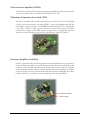
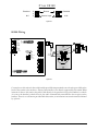
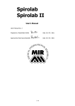
Revision 2.0 INSTALLATION & U SER GUIDE Revision 2.0 CAREHAWK INC. CH1000 Installation & User Guide CareHawk Inc. 229 Westforest Trail • Kitchener Ontario • Canada • N2N 3H8 Phone 519.745.2226 • Fax 519.743.8883 www.carehawk.com Disclaimer This manual has been validated and reviewed to be accurate for the CH1000 Series Communications System at the time of this manual’s production. However, the information contained in this document is subject to change without notice. Support for various features listed herein, is subject to the software version(s) provided with the system. CareHawk Inc makes no warranty of any kind with regard to this manual, and assumes no liability for damages incurred directly or indirectly from errors, omissions or discrepancies in relation to this manual. FCC Information All equipment parts of the CH1000 system comply with part 15 of the FCC Rules. Operation is subject to the following two conditions: (1) the equipment may not cause harmful interference. And (2) the equipment must accept any interference received, including interference that may cause undesired operation. NOTE: This equipment has been tested and found to comply with the limits for a Class A digital device, pursuant to part 15 of the FCC rules. These limits are designed to provide reasonable protection against harmful interference when the equipment is operated in a commercial environment. This equipment generates, uses, and can radiate radio frequency energy and, if not installed and used in accordance with the instructions, may cause harmful interference to radio communications. Operation of this equipment in a residential area is likely to cause harmful interference in which case the user will be required to correct the interference at his/her own expense. WARNING: Changes or modifications not expressly approved by CareHawk Inc. could void the user’s authority to operate the equipment. Industry Canada Compliance Statement This Class A digital apparatus complies with Canadian ICES-003. (Cet appareil numerique de la classe A est conforme a la norme NMB-003 Canada) ii TABLE OF CONTENTS System Overview ................................................................4 System Primary Component Overview....................................5 CH1000 Cabinet ..........................................................5 SS16 Security Switching Card ......................................7 DA1 Display Administrative Console .............................7 AF125 Audio Amplifier..................................................8 TC1 Telephone Communications Card..........................8 IA1 Intercom Amplifier ..................................................8 CR16 Camera Routing Card.........................................9 System Accessories Overview.............................................. 10 System Accessory Feature Summary .......................... 10 CS50 Call Station....................................................... 11 CS100 Call Station..................................................... 11 CS150 Call Station..................................................... 12 HS100 Handset Station .............................................. 12 HS120 Handset Call Station ....................................... 13 CH1000 Central Cabinet Mounting ....................................... 14 CH1000 Cabinet Features .......................................... 15 System Power Requirements...................................... 15 System Power Wiring ................................................. 16 CH1000 Connections ................................................. 17 SS16 Mounting .......................................................... 18 CH1000 to SS16 Wiring ............................................. 19 SS16 to End Device Wiring......................................... 20 CS50 Wiring .............................................................. 21 CS100 Wiring ............................................................ 22 CS150 Wiring ............................................................ 23 HS100 Wiring ............................................................ 24 HS120 Wiring ............................................................ 25 CR16 Installation ....................................................... 26 Camera Wiring........................................................... 26 DA1 Wiring .............................................................. 27 PBX Connections ....................................................... 28 General Purpose I/O Connections ............................... 29 Program Inputs .......................................................... 31 Microphone Input ....................................................... 31 AF125 Amplifier Connections ...................................... 32 Master Clock Connections .......................................... 32 Appendix A .............................................................. 33 User’s Guide.............................................................. 34 Phone Codes ............................................................. 36 3 1 Chapter System Overview Ethernet CH1000 Central Cabinet Microphone 12:00 Digital Clocks DA1 Analog C.O. Port(s) Remote Displays PBX Digital Video Recorder Video Balun Security Switching Card (SS16) Music Source Speaker Speaker CS100 Call Station PIR Sensor AF125 Amplifier Figure 1 4 Video Balun Camera PIR Sensor T he CareHawk CH1000 is a distributed, multi-channel, microprocessor-controlled security communication system. The system architecture allows for up to a maximum of eight Security Switching Cards (SS16), and eight display phones (DA1). Each SS16 contains 16 independent output audio/device ports, and is designed to be remoted from the central cabinet. Each SS16 can be located close to the central cabinet if desired, however to take advantage of the reduced wiring requirements, it is typically remoted elsewhere in a facility. It can be anywhere from a few hundred or a few thousand feet away from the central cabinet1. The system contains two independent 25V audio channels which can be used for paging/program material distribution as well as intercom (when equipped with an IA1 intercom amplifier). The system is controlled via a Display Administrative Console (DA1). A CH1000 system can have up to eight DA1s installed. Any # from 1 to a maximum of 8 of the phone ports are available for connection to a PBX system via standard analog CO ports2. It is recommended that at least one of the ports be left available for a DA1 when using multiple ports to interface with a PBX/KSU). System Primary Component Overview Central cabinet (CH1000) The CH1000 is the central equipment cabinet for the security communication systems. Each CH1000 provides for up to 128 audio/I/O ports and up to eight DA1 Display Administrative Consoles, as well as the following connections on the MI100 Main Interface Card (See Figure 16 for location of all ports): • Six input and 5 open collector output contacts (via keyed terminal strips). Open collector outputs are shared with two dry contact outputs (with N.O. and N.C. contacts available) • Any combination of phones or analog C.O. PBX interface ports totaling 8 • One microphone port (terminal strip) • Two Music source inputs (terminal strip) • Ethernet connectivity (RJ-45 jack) • RS-485 port for driving external digital clocks (RJ-45 or terminal strip) Attainable distances of the SS16 from the central cabinet are dependent on audio loading, and the losses deemed acceptable over that distance. 1 5 The cabinet is made of 18 gauge steel with a durable powder coat finish. The cabinet can be wall or rack-mounted. The overall cabinet dimensions are 18 1/2” high x 17” wide x 5 3/8” deep. See Figure 13 for full mounting details. Figure 2 6 Switching Security Card (SS16) An SS16 adds 16 audio/device ports that provide annunciated call-in with half-duplex communications capabilities between the DA1. Security sensors, speakers, and call-in switches can all be used with any of the 16 ports. The SS16 is designed to be a distributed component, and as such can be wall- or ceiling- mounted. SS16’s are housed in a metal cabinet similar to a network hub, and are easily used for retrofitted in existing installations (requires field wiring to be adapted to RJ45 terminated CAT5 cable). Up to eight SS16’s can be added to each CH1000 system for a total of 128 ports. Each SS16 requires only one CAT5/RJ45 termination between each SS16 and the central cabinet for basic operation2. With the video option, a second CAT-5 cable in needed. Figure 3 Display Administrative Console (DA1) Each DA1 provides a control center for all paging, intercom, security, and telephone communications. The DA1 has a visual as well as an audible indicator for incoming calls. The built-in memory allows for 8 speed dials and 99 stored numbers in a visual directory. The screen is backlit and adjustable for the attendants convenience. Screen icons simplify identifying the current status of the DA1. Six soft keys are provided for use with the dynamic menu system. The easy to use menu system allows for distributing program sources and pages to zones or all speakers without the need to remember long complicated number sequences. Arrow keys are provided to allow for easy scrolling through the call queue, directory, and menus. Figure 4 Basic operation provides two independent audio channels, +12VDC power, and RS-485 data transmission to each SS16 over a single CAT5 cable. 2 7 120 watt Power Amplifier (AF125) An AF125 is the external 120 Watt program/paging amplifier used with the system. This unit can be wall mounted or rack mounted. Output is 25V rms. Telephone Communications Card (TC1) The TC1 is a card that allows for the interconnection of a DA1 console to the CH1000 system, as well as connection of an analog PBX C.O. port the CH1000 system. The TC1 is installed as a plug in module on to the MI100 interface card. One TC1 is required for every DA1, and up to eight can be used with a system. When using it for PBX connectivity, a phone on the PBX system can gain access to paging and intercom functions on the CH1000 system just like a phone that is locally connected. Figure 5 Intercom Amplifier Card (IA1) An IA1 is a module that provides the talk/listen audio amplification for conversations between a DA1 and a remote room. The IA1 provides the means for a half duplex audio channel, as well as digital audio filtering of all talk and listen audio. The use of digital audio filtering means that typical room characteristics that make it difficult to listen to someone, are less of a factor, and the listen audio becomes more intelligible at the DA1 handset. One IA1 is required for systems requiring intercom functionality. VOX Sensitivity Adjust Talk Level Adjust 8 Figure 6 Camera Routing Card (CR16) The camera routing card is an optional add on card within the SS16 module. It facilitates the connection of UTP cameras on all SS16 device ports, and then feeds one video channel at a time to 3 rd party video monitoring equipment. It can be factory installed onto an SS16, or added to an SS16 on site at a later date if required. The use of this optional card requires one additional CAT-5 cable to be run to the SS16 for taking the video feed back to the 3rd party monitoring equipment. Each CH1000 system can have up to 8 CR16’s (assuming the system has 8 SS16’s), for a total of 8 simultaneous video feeds per system. Through programming (via CareHawk Settings software), camera sequencing can be setup at selectable intervals, between a selectable group of cameras. Camera sequencing can then be enabled/disabled as desired by a DA1 phone by using the on-screen menus. Adding a CR16 to an SS16 requires no software upgrades or system configuration. As soon as the CR16 is present and the cabling is in place, the system is video ready. Figure 7 9 System Accessories System Accessory Feature Summary Station Model # Station Feature CS50 CS100 CS150 HS100 Single Gang Stainless Steel Wall Plate Dual Gang Stainless Steel Wall Plate ? ? ? ? Can Originate Call ? ? Silicon Call Button ? ? ? ? Silicon Privacy Button ? Visual Call Assurance ? Illuminated Privacy button ? Grounded Audio Xfmr Center tap Privacy Audible Call Assurance ? ? ? ? Durable Audio Handset w/hookswitch Rocker switch with Momentary Call & Maintained Privacy Speaker connections ? ? ? ? RJ-45 Connectivity ? ? ? ? ? RJ-45 UTP Camera Connectivity Sensor/Device Input for N.O. & N.C., jumper HS120 ? ? ? ? Table 1 10 ? ? ? CS50 Call Station A CS50 is a basic single gang stainless steel call station with a rocker switch. The switch provides for a momentary call and lockable privacy position. This station provides RJ-45 connectivity for connection to the SS16, and stripped wire ends facilitating crimp connection onto cable going to the associated speaker. Figure 8 CS100 Call Station A CS100 is a basic single gang stainless steel call station with an epoxy coated silicon call button. The switch provides a momentary contact closure for making a call. This station comes with RJ45 connections on the rear for the connection from the SS16 which are clearly labeled on the board. In addition there are also connections for a speaker, security sensors and optional camera. The CS100 station does not provide any power to the camera, so when connecting a camera a separate power source is required. This station acts as a cable concentrator for a location to allow a single CAT5 cable run back to the SS16. Figure 9 11 CS150 Call Station A CS150 is an enhanced single gang stainless steel call station with an epoxy coated silicon call and privacy button, both of which can be illuminated when pressed. When placing a call, the call button will be illuminated only after the central equipment has received the call, so it acts as a true visual call assurance indicator. At the same time, an audible call assurance tone will be provided by a buzzer on the station3. The privacy button can be pressed at any time to mute the listen audio from a room during normal intercom conversations, and provides an orange illumination when activated. Both switches provide a momentary contact closure when pressed. This station comes with an RJ45 jack on the back for connection to the SS16 which is clearly labeled on the board. In addition, there are also connections for a speaker, security sensor, open collector driver, and optional camera (also RJ-45). Figure 10 HS100 Handset A HS100 is a basic single gang stainless steel handset station. The handset allows for a private conversation by automatically switching the intercom from the associated room speaker when taken offhook. There is no call button on this station, so it is only capable of facilitating half duplex audio communications that is initiated from a phone. Figure 11 Audible alert tone is a local jumper selectable function of each CS150 station. Each CS150 station is factory set to enable the audible alert tone. See figure 23 to determine how this tone can be defeated with the buzzer enable/disable jumper setting. 3 12 HS120 Handset/Call Station A HS120 is a basic double gang stainless steel combination handset and call station. The rocker switch provides for a momentary call and lockable privacy position. The handset allows for a private conversation by automatically switching the intercom from the associated room speaker. Taking the handset off-hook with the call switch in the privacy position will not override the privacy function. The call button must be returned to the center position for the handset audio to be heard at the phone. Figure 12 13 2 Chapter System Installation CH1000 Cabinet Mounting The CH1000 cabinet is designed for mounting on a wall. The diagram below shows the location of the four mounting holes. Holes are located on 16” centers to accommodate fastening to wall studs where possible, however the cabinet weight including power supply, 8 TC1’s and one IA1 is only 27 lbs. The cabinet should be mounted to the wall using four #8x 2” screws appropriate to the wall type. 17.00" 2.00" 12.75" 18.50" 3.75" 16.00" Figure 13 14 CH1000 Cabinet Features Figure 14 below shows an internal picture of the CH1000 system. All field wiring enters the cabinet from the bottom via dual knockout holes (7/8” and 1 ¼”). A knockout has also been provided to bring AC power into the cabinet. The door is hinged on the left side as illustrated below, and equipped with a keyed lock to prevent unauthorized access to the system hardware. Since the cabinet contains a total of 6 knockout holes, there is plenty of cable entry space for bringing field wiring into the cabinet. When bringing field wiring into the cabinet, it is recommended that DA1/phone cabling enter in a different knockout hole then SS16 wiring. It is also recommended that the wiring to/from the external audio amplifier be routed through a knockout hole on its own in an effort to prevent coupling between cables. Figure 14 System Power Requirements The CH1000 system requires 120VAC at 1.0 amp maximum (excluding power requirements of the AF125 – 115 VAC, 3.0 amps at rated power output). The system fuse is 1.0 amp slow blow, and is located on the PDB1 (just above transformer show in Figure 15) 15 System Power Wiring Each CH1000 system is provided with a standard 6 ft line cord which mates with the 120 VAC socket on the bottom edge of the central cabinet as shown below. Plug the receptacle end of the line cord firmly into the socket on the bottom of the cabinet, and plug the other end into a 120 VAC outlet. If power will be entering the cabinet through conduit instead, then the following steps need to be followed: 1. Inside the CH1000 cabinet, disconnect the black and white wires connecting the AC socket to power distribution board (PDB1) terminal strip TS1. Disconnect the green ground wire connecting the AC socket to the ground stud on the bottom of the cabinet. 2. Install appropriate wires through conduit and into the cabinet. 3. Attach the ground wire entering the cabinet to the ground stud located on the bottom of the cabinet (labeled with a green ground symbol) using a #6 ring lug. Ensure that the ground stud at the bottom of the cabinet is still wired to the appropriate pin in terminal strip TS1 located on the PDB1. 4. Using a slot screw driver, loosen the two screws which fasten the terminal strip onto the PDB1. 5. Using the same slot screw driver, connect the black (Hot), and white (Neutral) wires entering the cabinet into the appropriate pins in terminal strip TS1 on the PDB1. Observe the markings on the PDB1 to determine the correct position, as well as using the picture below to determine correct wire colors. Figure 15 16 CH1000 Connections The figure below shows all of the connections required to the MI100 Main Interface board found inside the CH1000 cabinet. TC1 Slot #8 TC1 Slot #1 Ethernet Port Microphone Input SS16 Ports (8) RS-422 to Slave Clocks DA1/Phone Ports (8) PBX C.O. Ports (2) Music Source Inputs (2) External Display General Purpose Outputs (Top) General Purpose Inputs (Bottom) Figure 16 17 SS16 Mounting The SS16 is designed to be located in a hallway or corridor of a building in a location near devices that will connect to it. The cabinet should be located away from any machinery as well as florescent lighting, and if necessary SS16 cabling should cross power cabling at right angles (avoid long parallel runs). The SS16 cabinet can be installed on a wall or above the ceiling tile in the air plenum. The SS16 can be located at a distance from the central cabinet. Wiring losses need to be taken into consideration to determine the maximum distance an SS16 can be located away from the central cabinet. Powering remote devices such as motion sensors, etc from the SS16 is possible. When it’s required to source > 150 mA DC at 12V to remote devices, a local class II rated +12VDC power source can be connected to the 2.1mm DC power jack located on the side of the chassis as shown in figure 19. Figure 17 below shows the mounting brackets for the SS16. #8 screws should be used when attaching the SS16. Choose the appropriate type of screws for the wall type being fastened to. The top mounting hole is masked off so that a ring lug and 16 AWG wire can be used for connecting the chassis to a solid earth or electrical ground. This connection is necessary, as it provides a means of diverting high level transient voltages entering the SS16 on the audio lines to a solid earth ground. Mounting Hole Audio/Data Port (See Figure 16) Audio/Video Port (See Figure 16) Device Ports Mounting Hole Figure 17 18 CH1000 to SS16 Wiring The wire required for connection from the CH1000 cabinet to all SS16’s is standard CAT3,5, or 5e 24 AWG cable. All RJ45 connections to the SS16 and central cabinet must follow the Electronics Industry Association (EIA) 568A or 568B standard4, since all RJ45 connectors coming from the SS16 and central cabinet conform to this. It does not matter which standard is used, as long as the same one is used consistently throughout the entire system installation. The pin out for the two RJ45 SS16 ports is shown here as well as directly on the top cover of the SS16: SS16 AUDIO/DATA PORT RJ-45 JACK PIN # SS16 AUDIO/VIDEO PORT RJ-45 JACK PIN # (4) DATA_A (3) GND (2) CH #1 AUDIO (1) CH #1 AUDIO DATA_B +12VDC IN CH #2 AUDIO CH #2 AUDIO (5) (6) (7) (8) RJ-45 JACK PIN # RJ-45 JACK PIN # (4) VIDEO+ (3) GND (2) CH #3 AUDIO (1) CH #3 AUDIO RJ45 JACK VIDEO +12VDC IN CH #4 AUDIO CH #4 AUDIO (5) (6) (7) (8) RJ45 JACK Figure 18 Within the central cabinet eight SS16 ports are found. Figure 16 shows the interconnection ports. The SS16 ports should be used in the numerical order shown. A +12 VDC jack is also provided on this module to allow for it to be locally powered. This jack should be used in either of the following two situations: • SS16 needs to be located farther from the central cabinet than the maximum recommended distance of 1400 feet (this distance is based purely power consumption of the SS16, and does not take into account the audio loads connected to the SS16). • SS16 needs to source +12VDC power to a significant number of end devices (such as motion sensors etc). The more devices requiring power, the greater the power losses in the cable feeding the SS16 from the central cabinet, which in turn reduces the distance the SS16 can be located from the central cabinet. When powering numerous devices from the SS16 audio/device ports, it is recommended that it be locally powered from a class II +12VDC power source. Since the maximum distance the SS16 can be located from the central cabinet is directly related to the power being consumed by the SS16 and the end devices drawing power from the device ports. By locally powering the SS16, the distance limitation based on power consumption goes away. The only distance limitation left relates to the audio power being drawn by the SS16 speaker ports. EIA568A/568B is a common standard used for computer network wiring. See appendix A for further details about how to wire to this standard. 4 19 SS16 to End Devices The SS16 allows for connection of up to 16 devices. The devices can be any of the REDy Corp standard stations listed in table 1. They can also be direct connection of 25V audio transformer/speaker, or UTP camera (utilizing a video balun). Typical installations will connect these types of devices to one of the standard room stations prior to connecting to the SS16, however it is not mandatory. When connecting speakers the following limits must be followed. No more than 25 watts per port and no more than 35 watts peak per SS16 can be connected. The required wire to go from the SS16 to the end devices is CAT5. The wire is terminated at the SS16 with an RJ45 plug of the appropriate type for the CAT5 cabling being used. The device end of the wire can be left as a pig tail or terminated with a RJ45 connector depending on the application. Figure 19 below shows where the devices are connected to the SS16. The diagram found on the cover of the SS16 lists the port numbers as well as the function of each pin within each connector. For installations needing to deploy motion sensors etc, requires wiring them into a CS150 call station before connecting back to an SS16 (See Figure 22). The SS16 also provides +12 VDC power at each device port for powering some sensor devices, with the combined current consumption of all 16 ports limited at 150 mA. It is recommended that if more than a few sensors per SS16 are required, that the SS16 be provided with local power via the 2.1 mm DC jack on the side of the SS16. If this is not practical, or the +12 VDC supply is not appropriate for the devices being used, then a completely separate power source must be used. When power is applied to an SS16, the green status LED (shown on the right side of figure 19 beside the DC input jack), will flash at a steady rate, indicating the unit is operating properly. Sensors can be connected directly to an SS16 device port, as long as the following specific limitations are understood. • Sensor/device must provide a normally open contact during idle going closed during activation. Normally closed contacts are not supported unless going through a CS150 call station. • Contact closure provided by the sensor will be treated like a normal call-in to the system, and will not have sensor input status. • Sensor/device activation time must be a minimum of 50 milliseconds to be recognized. Device Port(s) Figure 19 20 2.1mm 12 VDC INPUT JACK From class II Source ONLY. CS50 Wiring 1 8 1 8 CH #1 AUDIO CH #1 AUDIO GND DATA_A DATA_B +12 VDC IN CH #2 AUDIO CH #2 AUDIO MODEL: SS16 CH #3 AUDIO CH #3 AUDIO GND VIDEO+ VIDEO+12 VDC IN CH #4 AUDIO CH #4 AUDIO +12 VDC IN 8 16 7 15 14 6 PORT 1-16 CONNECTOR PINOUT STATUS INDICATOR 1 8 1 8 8 1 5 VIDEO+ VIDEOCALL-IN GND AUDIO AUDIO CALL-IN PWR GND +12VDC OUT 13 YELLOW 4 12 3 11 2 10 25V: 8 OHM COM BLUE 1/4W 1/2W BLUE 1W 2W 4W 1 8 1 9 8 1 Figure 20 Connection to this station from an SS16 port can be done through an RJ-45 terminated CAT-5 cable (straight through, not cross-over cable). Connections to the audio transformer requires installer provided crimped connections onto the blue pair of wires coming off of the station. The yellow wire coming from the station must be wired as shown above for the privacy position of the toggle switch on the front of the station to be functional. There are no specific distance limitations between the CS50 and the SS16. The only distance limitation involves the acceptable cable losses for the audio over CAT-5 cable from the CH1000 central cabinet, and the speakers involved. 21 CS100 Wiring 1 8 1 8 CH #1 AUDIO CH #1 AUDIO GND DATA_A DATA_B +12 VDC IN CH #2 AUDIO CH #2 AUDIO MODEL: SS16 CH #3 AUDIO CH #3 AUDIO GND VIDEO+ VIDEO+12 VDC IN CH #4 AUDIO CH #4 AUDIO +12 VDC IN STATUS INDICATOR 8 16 7 15 6 PORT 1-16 CONNECTOR PINOUT 1 8 14 1 8 8 1 5 VIDEO+ VIDEOCALL-IN GND AUDIO AUDIO CALL-IN PWR GND +12VDC OUT 13 4 12 3 11 2 10 25V: 8 OHM COM 1/4W 1/2W 1 8 1 1W 9 8 2W 1 4W VIDEO BALUN Figure 21 Connection to this station from an SS16 port can be done through an RJ-45 terminated CAT-5 cable (straight through, not cross-over cable). Connections to the audio transformer may be wired directly into a terminal strip labeled TS1 provided on the back of the station as illustrated above. Privacy functionality is not supported directly from this station. If required, another model of REDy Corp. call station such as the CS50, CS150, or HS120 should be chosen. See table 1 for a complete listing of station models vs features. When installing cameras, standard composite video security cameras may be used. For proper transmission of the video signal over UTP requires the use of a video balun as shown in the illustration above. The balun should be located as close to the camera as possible, however the balun/camera assembly may be located a significant distance away from the CS100 if required5. When using UTP cameras, the video balun is often integrated within the camera, so an external balun module is not required. Connection of the video signal to the CS100 station is done via standard RJ-45 terminated CAT5 cable. The CS100 simply acts as a cable concentrator, and facilitates the ability to combine the video and audio signals onto a single CAT-5 cable going to the SS16 device ports. No video processing takes place on the CS100, or SS16. The video pair is connected to pins 1 & 2 on CS100 port P1 labeled CAMERA. Distance limitation is dependent on the overall distance from the camera to the head end equipment (ex: DVR), and the type/quality of the video balun chosen for the application. There is no direct limitation on the distance from camera to CS100. 5 22 CS150 Wiring 1 8 1 8 CH #1 AUDIO CH #1 AUDIO GND DATA_A DATA_B +12 VDC IN CH #2 AUDIO CH #2 AUDIO MODEL: SS16 CH #3 AUDIO CH #3 AUDIO GND VIDEO+ VIDEO+12 VDC IN CH #4 AUDIO CH #4 AUDIO +12 VDC IN 8 16 7 15 6 14 PORT 1-16 CONNECTOR PINOUT 1 8 8 1 5 STATUS INDICATOR 1 8 VIDEO+ VIDEOCALL-IN GND AUDIO AUDIO CALL-IN PWR GND +12VDC OUT 13 4 12 3 11 2 10 1 Sensor JUMPERS - Ext. Power Source + 8 1 RELAY SPDT 9 8 1 Camera 25V: 8 OHM COM 1/4W 1/2W 1W VIDEO BALUN 2W 4W Figure 22 Connection to this station from an SS16 port can be done through an RJ-45 terminated CAT-5 cable (straight through, not cross-over cable). Connections to the audio transformer may be wired directly into a terminal strip labeled TS2 provided on the back of the station as illustrated above. This station fully supports privacy functionality, but unlike the CS50, CS100, and HS120, does not require a center tap connection to the audio transformer. When installing cameras, standard composite video security cameras may be used. For proper transmission of the video signal over UTP requires the use of a video balun as shown in the illustration above. The balun should be located as close to the camera as possible, however the balun/camera assembly may be located a significant distance away from the CS100 if required6. When using UTP cameras, the video balun is often integrated within the camera, so an external balun module shown above is not required. Connection of the video signal to the CS100 station is done via standard RJ-45 terminated CAT-5 cable. The CS100 simply acts as a cable concentrator, and facilitates the ability to combine the video and a udio signals onto a single CAT-5 cable going to the SS16 device ports. No video processing takes place on the CS100, or SS16. The video pair is connected to pins 1 & 2 on CS150 port P2 labeled CAMERA .. The CS150 also allows for connection of a sensor into terminal strip TS1 (pins labeled SENS and GND). This can be a motion sensor, a door contact, etc. The CS150 comes shipped from the factory configured to accept a normally closed contact during idle, and going open when activated. If a normally open contact arrangement is required, a jumper can be moved on P1 to accommodate this (see illustration below for appropriate jumper position). See location marked JUMPERS indicated above in figure 22 to locate P1. When a sensor input is activated, the CS150 provides no visual or audible indication of the sensor being active, thereby providing a silent alarm. The systems response to the sensor activation is configured on a port by port basis in the REDySet configuration software. Distance limitation is dependent on the overall distance from the camera to the head end equipment (ex: DVR), and the type/quality of the video balun chosen for the application. There is no direct limitation on the distance from camera to CS150. 6 23 P1 on CS150 Enabled N.C. 6 4 2 Buzzer Disabled Sensor Input N.O. Figure 23 HS100 Wiring 1 8 1 8 CH #1 AUDIO CH #1 AUDIO GND DATA_A DATA_B +12 VDC IN CH #2 AUDIO CH #2 AUDIO MODEL: SS16 STATUS INDICATOR 16 7 15 6 14 25V: 8 OHM COM 1/4W CH #3 AUDIO CH #3 AUDIO GND VIDEO+ VIDEO+12 VDC IN CH #4 AUDIO CH #4 AUDIO +12 VDC IN 8 BLUE 1/2W 1W BLUE PORT 1-16 CONNECTOR PINOUT 1 8 2W BLUE 1 8 5 VIDEO+ VIDEOCALL-IN GND AUDIO AUDIO CALL-IN PWR GND +12VDC OUT 4W SLATE 13 8 1 BLUE/ WHITE 4 12 3 11 2 SLATE 10 1 8 8 1 1 9 Figure 24 Connection to this station is done with installer provided crimp terminals onto the wires provided on the back of the station as shown above. Privacy functionality is not directly supported by this station. When intercom is done to this station, the audio is fed directly to the speaker as long as the handset is on-hook. As soon as the handset is taken off hook, the audio is immediately transferred to the ear piece on the handset. There is no call button provided with this station, so an intercom conversation must be initiated by a phone. 24 HS120 Wiring 1 8 1 8 CH #1 AUDIO CH #1 AUDIO GND DATA_A DATA_B +12 VDC IN CH #2 AUDIO CH #2 AUDIO MODEL: SS16 +12 VDC IN 8 16 7 15 6 14 BLUE CH #3 AUDIO CH #3 AUDIO GND VIDEO+ VIDEO+12 VDC IN CH #4 AUDIO CH #4 AUDIO 25V: 8 OHM COM 1/4W 1/2W PORT 1-16 CONNECTOR PINOUT STATUS INDICATOR 1 8 1 8 8 1 5 VIDEO+ VIDEOCALL-IN GND AUDIO AUDIO CALL-IN PWR GND +12VDC OUT YELLOW 13 4 12 3 11 2 10 1 1W BLUE 2W 4W 8 1 9 8 1 Figure 25 Connection to this station from the SS16 is done via RJ-45 plug. Connections to the audio transformer are done by crimping onto the blue pig tail wires extending from the station. Privacy functionality is supported by connecting the center tap of the 25V audio transformer to the yellow pig tail wire extending from the station. When intercom is done to this station, the audio is fed directly to the speaker as long as the handset is on-hook. As soon as the handset is taken off hook, the audio is immediately transferred to the ear piece on the handset. The toggle switch on the front of the station provides a momentary call position, and a maintained privacy position to mute the listen audio at the telephone. 25 CR16 Installation The CR16 is intended to be installed within the SS16 chassis. When ordering an SS16, it is possible to have it shipped from the factory pre-installed, however if required, it can be installed on site as well. The steps required to install it are as follows: • Unplug all cabling entering the SS16 from the left side of the chassis (closest side in the photo below). If power is being provided locally, the power will also need to be removed. All device port cabling does NOT need to be removed. • Using a Philips screwdriver, remove the two screws found on the device port side of the SS16 chassis (area highlighted with RED circles in picture below). • Gently grasp the top and bottom edges of the cover close to the device ports and tip upward slightly. • Now gently tap the entire cover to the left (opposite the device ports) until the two mounting tabs holding the left edge of the cover are free from the base. • Take the CR16, and place it component side down, and align with connector P14 on the SS16 (right behind the large device port connectors). The plastic mounting posts located on each end of the CR16 should line up directly with mounting holes found on the SS16 board. Snap the each mounting post into the SS16, and then press the center of the CR16 to fully seat the connector. • Re-install the cover, and mounting screws. Figure 26 Camera wiring Composite video cameras of the customers choosing can be used with this system. All that is required is the use of a video balun module local to the camera, as well as at the head end monitoring equipment. The balun modules simply convert the ground referenced composite video to a balanced video signal suitable for transmission over UTP, and then back again just before going into the central 3 rd party monitoring equipment (ie: Digital Video Recorder). If the system is configured appropriately, the end user can select directly on the DA1 which camera is to be routed to the central monitoring equipment. Only one video signal per SS16 can be active at any one time. 26 DA1 Wiring The DA1 ports are found in the lower left corner within the CH1000 Cabinet (See Figure 16 for exact location). Up to eight DA1’s can be connected to the CH1000, and each port requires a TC1 card to be installed in the appropriate slot position (see figure 16 for TC1 slot locations). The slot # corresponds directly with the physical DA1 port number as shown on the DA1 port connector label. The DA1 consoles require power for the display, so a CH1000 system is designed to supply only the first DA1 with power (corresponding to DA1 port 1). This is done as a method of providing console functions in the case of a power failure when a UPS is used. Subsequent ports making use of DA1 phones will require the use of the AC adapter provided with the phone. All DA1’s are wired with CAT-5 cable and terminated with RJ45 plugs. Figure 27 below shows the connections. Any DA1’s connected to ports 2-8 must utilize the power adapter provided with each DA1. If preferred, ports 2-8 can be connected to standard DTMF phones also, but it is recommended that the adapter shown in figure 28 be used directly at the phone. This will allow the installer to use RJ-45 plugs throughout the installation, and provide a convenient means of converting this connection to the standard RJ-11 required by the phone. The DC power plug can be left un-connected, since no power is being provided on it when being used with DA1 ports 2-8. CAUTION: The CH1000 system does not provide the appropriate protection for field wiring extending from the central cabinet to a DA1 phone or any other phone intended for use in exposed plant applications. Attempts to do so must follow the requirements of sections of the CEC and NEC (section 800.44, 800.90) depending on jurisdiction. Failure to provide adequate protection will void the system warranty. DA1 PORT(s) 2-8 DA1 PORT 1 RJ-45 JACK PIN # (4) RING (3) No Connect ( 2 ) No Connect ( 1 ) No Connect RJ-45 JACK PIN # (5) TIP No Connect (6) No Connect ( 7 ) No Connect ( 8 ) (4) RING ( 3 ) No Connect (2) 16 VAC (1) 16 VAC TIP No Connect No Connect No Connect RJ-45 JACK RJ-45 JACK Figure 27 27 (5) (6) (7) (8) The DA1 is provided with the adapter shown below in figure 28 (model # ADA1). This adapter provides the conversion from RJ45 to RJ11 for connection to the back of the DA1 console. This adapter also breaks out the power connection to supply the first DA17. Figure 28 PBX Connections The PBX ports are identical to the DA1 ports (See Figure 16 for exact location). For each PBX port that is used, one less DA1 port is available. For example if two PBX ports are to be used, only six DA1 ports are available. A maximum of eight ports are available on the CH1000 system, which are designed to be connected to analog C.O. ports on the PBX, since the TC1’s provide the necessary loop current (48VDC). If the PBX being connected is capable of recognizing caller ID information, then the corresponding CH1000 DA1 port should be configured as a “Caller ID” phone. This will ensure that all caller ID information from the CH1000 can be passed along to the PBX phones that are caller ID capable. PBX PORT(s) RJ-45 JACK PIN # (4) RING (3) No Connect (2) No Connect (1) No Connect RJ-45 JACK PIN # (5) TIP No Connect (6) No Connect (7) No Connect (8) RJ-45 JACK WARNING: This system is NOT designed for direct connection to the public switched telephone network (PSTN). Any attempts to do so would be in direct violation of FCC part 68 and Industry Canada CS-03 regulations (depending on jurisdiction), and will void the system warranty. 7 Power is provided out to only the first DA1 port. All other DA1 phones must make use of the AC adapter provided with the phone. 28 General Purpose I/O Connections The general purpose I/O connections are found inside the CH1000 cabinet (See Figure 16 for exact location). The figure below shows the pin outs of the double row terminal strip. There are 6 general purpose inputs, and 6 open collector outputs/2 dry contact outputs (dry output contact rating of 1 amp). See next page for further details. Configuration of these ports is done through CareHawk Decisions software. GENERAL PURPOSE INPUTS 2 3 4 5 6 GROUND OR COMMON INPUT # 6 1 GND Input Terminal Strip (Lower terminal strip) INPUT # 1 INPUT # 5 INPUT # 4 INPUT # 3 INPUT # 2 Figure 29 1 GENERAL PURPOSE OUTPUTS 2 3 4 5 N.C.2 GND Output Terminal Strip (Upper terminal strip) GROUND OR COMMON DRY CONTACT #2 N.C. OPEN COLLECTOR #5/DRY CONTACT #2 N.O. OPEN COLLECTOR #4/DRY CONTACT #2 COM OPEN COLLECTOR #3/DRY CONTACT #1 N.C. OPEN COLLECTOR #2/DRY CONTACT #1 N.O. OPEN COLLECTOR #1/DRY CONTACT #1 COM Figure 30 29 The chart below describes the jumper settings for the ports. The jumpers are found on the MI100 interface board directly behind the I/O terminal strip. General Purpose Output Port Configuration TERMINAL STRIP PIN # JP13 JP14 JP15 JP16 JP17 A B - - - - A B - - - A B - - - - - - - A B B - B A B - 1 2 3 4 5 6 7 OUTPUT FUNCTION Open Collector #1 COM: Dry Contact #1 Open Collector #2 N.C. Dry Contact #1 Open Collector #3 N.O. Dry Contact #1 Open Collector #4 COM: Dry Contact #2 Open Collector #5 N.O. Dry Contact #2 N.C. Dry Contact #2 Ground When a combination of open collector and dry contacts is required, JP13, JP14, and JP15 should be in position A (farthest from terminal strip), and JP16, JP17 should be in position B (closest to terminal strip). This will provide 3 open collector outputs on terminal strip pins 1-3, and one normally open dry contact on pins 4 & 5. Please note that the dry contact is rated for 1A Max switching, 2A carrying for simple resistive loads up to 60VDC. Rated at 0.5A for 120VAC. Table 2 The schematic below is provided for illustration purposes only. JP13 JP14 JP15 JP16 D5 SMBJ10A 1 2 3 4 5 6 7 9 U15 I1 VCC I2 I3 I4 I5 I6 I7 GND ULN2003 8 1 2 3 1 2 3 1 2 P34B 1 O1 O2 O3 O4 O5 O6 O7 16 15 14 13 12 11 10 R99 R100 R101 R102 R103 SIG 2 3 1 XK XK XK XK XK +12 D6 JP17 3 12VDC 5 1 6 10 2 9 RL2 +12 D7 SIG 30 12VDC 5 1 6 10 2 9 RL3 2 3 8 9 10 11 12 13 14 GENERAL PURPOSE OUTPUTS Program Inputs 1 IN GND 2 IN GND The program inputs are located inside the CH1000 cabinet (See Figure 16 for exact location). Below is the pin outs for the removable terminal strip. The inputs are designed for 1V RMS with a 10KO input impedance. Program sources that produce signal levels in excess of this need to be attenuated prior to connecting to the CH1000 system. Program sources can be anything from a 3 rd party AM/FM tape/tuner to a CD player or mixer. The minimum wire type recommended from the program source to the CH1000 is 24 awg shielded cable. The shield for the cable MUST be terminated at one end only, and not both. GROUND AUDIO SOURCE #2 INPUT GROUND AUDIO SOURCE #1 INPUT Figure 31 Microphone Input IN+ IN- SW GND The microphone input is located inside the CH1000 cabinet (See Figure 16 for exact location). Below is the pin outs for the removable terminal strip. The input is designed for a dynamic low impedance microphone. The microphone only becomes active for an all page, when the MIC SWITCH pin is connected to the GND pin. The microphone will continue to do an all call page until the switch opens again. MIC SWITCH COMMON AND SHIELD MIC SWITCH MIC AUDIO MIC AUDIO + Figure 32 31 AF125 Amplifier Connections The amplifier connections are made to terminal strips found on the top inside plate in the CH1000 cabinet. Connections are as follows. Both the input cable to the amplifier, and the output cable from the amplifier should make use of shielded cable. Inside CH1000 Cabinet SHLD + IA1 SHLD + BAL. 1. 25V AF125 120W EXTERNAL AUDIO COM BAL. 2. AMPLIFIER COM CT COM Figure 33 Master Clock Connections The CH1000 is capable of acting as a master clock. As such it can be set up to synchronize Sapling RS485 based slave clocks. The RS-485 port is located inside the CH1000 cabinet (See Figure 16). This port is wired as shown below. Pins 4 & 5 provide RS-422 communications to the Sapling clocks. (Feature not available at time of manual release. Contact factory to confirm when feature will be supported). RS-485 PORT RJ-45 JACK PIN # (4) DATA_A (3) GND (2) No Connect (1) No Connect RJ-45 JACK PIN # (5) DATA_B No Connect (6) No Connect (7) No Connect (8) Figure 34 32 APPENDIX A NOTE: Numbers 1-4 in the above illustration indicate the twisted pairs in the CAT5 cable. Pin # 1 2 3 4 5 6 7 8 Wire Color for 568A Green/White Green Orange/White Blue Blue/White Orange Brown/White Brown 33 Wire color for 568B Orange/White Orange Green/White Blue Blue/White Green Brown/White Brown USER’s GUIDE Basic Operation The CareHawk CH1000 system is designed around keeping things simple. The DA1 phone shown below is the main device used for controlling all system functions on a day to day basis (standard DTMF telephones can also be used). The DA1 comes pre-programmed with numerous menus, which can be easily navigated with the 3 soft keys found on both sides of the large display. Each menu provides easy to use prompts that guide you through the steps needed to initiate system functions. Everything from all call paging, zone paging, intercom to a single room, manual time tones, music distribution, and video camera activation can be initiated from the DA1 with the press of a button. System schedule programming can be done using a software tool called CareHawk Calendar. CareHawk Calendar allows all system events to be configured into a single calendar. When special schedules need to be employed, CareHawk Calendar offers the ability to program schedule templates, which can be made active at any time by following the schedule prompts on screen using the soft keys. D E A F B G C Figure 35 As calls from rooms within a facility come into the DA1, they will enter the call-in queue, and be displayed 4 calls at a time on the display. The calls will be listed in order of priority, with the highest priority call being at the top of the list. By lifting the handset, the highest priority call will automatically be connected. 34 Control Buttons: A Volume key: Adjusts the volume for the handset, headset, and handsfree speaker volume of the ringer tone. There are 8 ringer volume level settings. Default level is medium. B Handsfree key: Pressing this activates handsfree mode so you make and receive calls without lifting the handset. C Mute key: When activated, prevents the caller from hearing you through the handsfree, handset, or headset. D Hold keys: When doing an audio page, the talk audio is muted. When pressed during an intercom conversation, both the talk and listen audio is muted. Press again to restore the audio path. E Redial key: Displays the last 10 numbers dialed. When pressed, on screen menus guide you through the options. F Soft keys: Provides access to all on screen menu options. The menus change depending on which main menu is entered into. G Arrow keys: press to move the screen cursor when navigating through on screen options 35 Phone Commands Dial Sequence 00# 001…# Command Emergency Page All Emergency Page Inclusive Zones 002…# Emergency Page Exclusive Zones 01# 011…# Page All Page Inclusive Zones 012…# Page Exclusive Zones 013…# 014…# 020TT# Page Inclusive Speakers Page Exclusive Speakers Tone All 021TT…# Tone Inclusive Zones Dial Sequence Where … is the list of zones ( Zones: 01? 64 - Must be entered as 2 digits ) Where … is the list of zones ( Zones: 01? 64 - Must be entered as 2 digits ) Where … is the list of zones ( Zones: 01? 64 - Must be entered as 2 digits ) Where … is the list of zones ( Zones: 01? 64 - Must be entered as 2 digits ) Where … is the list of speakers Where … is the list of speakers Where TT is the tone number ( Tones: 00? 99 - Must be entered as 2 digits ) Where TT is the tone number ( Tones: 00? 99 - Must be entered as 2 digits ) Where … is the list of zones 022TT…# Tone Exclusive Zones ( Zones: 01? 64 - Must be entered as 2 digits ) Where TT is the tone number ( Tones: 00? 99 - Must be entered as 2 digits ) Where … is the list of zones ( Zones: 01? 64 - Must be entered as 2 digits ) 023TT…# Tone Inclusive Speakers Where TT is the tone number ( Tones: 00? 99 - Must be entered as 2 digits ) 024TT…# Tone Exclusive Speakers Where … is the list of speakers Where TT is the tone number ( Tones: 00? 99 - Must be entered as 2 digits ) 025# 026# 030P# 031P…# Play Emergency Tone Continuously Stop Emergency Tone Program Source All Program Source Inclusive Zones Where xxx is the list of speakers Where P is the program source ( Program Source : 1? 2 - Must be entered as 1 digit ) Where P is the program source ( Program Source : 1? 2 - Must be entered as 1 digit ) Where … is the list of zones ( Zones: 01? 64 - Must be entered as 2 digits ) 032P…# Program Source Exclusive Zones Where P is the program source ( Program Source : 1? 2 - Must be entered as 1 digit ) Where … is the list of zones ( Zones: 01? 64 - Must be entered as 2 digits ) 36 033P…# Program Source Inclusive Speakers Where P is the program source ( Program Source : 1? 2 - Must be entered as 1 digit ) 034P…# Program Source Exclusive Speakers Where … is the list of speakers Where P is the program source ( Program Source : 1? 2 - Must be entered as 1 digit ) 035P# End Program Source Where … is the list of speakers Where P is the program source ( Program Source : 1? 2 - Must be entered as 1 digit ) 050xxx# 051xxx# 0520# 0521# 060# 061xxx# 0700# 0701# 08# 0800xxx# 0801xxx# 0810x# 0811x# 0820# 0821# 0822# 083x# Video Camera Off Video Camera On Video Camera Sequence Off Video Camera Sequence On Call Forwarding Off Forward All Calls Cancel Main Alarm Clear Normal Call-Ins From Queue Sync System Time Turn Off Message Waiting Lamp Turn On Message Waiting Lamp Turn Off Output Turn On Output Turn Schedules Off Turn Schedules On Read New Schedules Disable/Enable Schedule Templates 084xxx# Remote Extension Call Pickup Where xxx is the camera number Where xxx is the camera number Where xxx is the extension to forward call to Where xxx is the extension Where xxx is the extension Where x is the output number Where x is the output number If x = 0, templates will be disabled and the system will use the standard schedule. If x is between 1and 5 inclusively, that template will be enabled until midnight when the system return to the standard schedule Where xxx is the remote extension 37