1
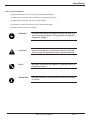
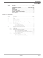
www.mgeups.com
EPS 7000
Single Module
Users Manual
EPS 7000 Single Module
IMPORTANT SAFETY INSTRUCTIONS
SAVE THESE INSTRUCTIONS – This manual contains important instructions for all EPS 7000 Single Module that
must be followed during operation of the equipment.
page ii
WARNING:
Opening enclosures expose hazardous voltages. Always refer
service to qualified personnel only.
ATTENTION:
L'ouverture des cabinets expose des tensions dangereuses.
Assurez-vous toujours que le service ne soit fait que par des
personnes qualifiees.
WARNUNG!
Das öffnen der Gehäuse legen gefährliche Spannungen bloss.
Service sollte immer nur von qualifizierten Personal durchgeführt
werden.
WARNING:
As standards, specifications, and designs are subject to change,
please ask for confirmation of the information given in this
publication.
ATTENTION:
Comme les normes, spécifications et produits peuvent changer,
veuillez demander confirmation des informations contenues dans
cette publication.
WARNUNG!
Normen, Spezifizierungen und Pläne unterliegen Anderungen.
Bitte verlangen Sie eine Bestätigung über alle Informationen, die in
dieser Ausgabe gemacht wurden.
NOTE:
This equipment generates, uses, and can radiate radio
frequency energy and, if not installed and used in accordance
with installation manual, may cause harmful interference to
radio communications. Operation of this equipment in a
residential area is likely to cause harmful interference in which
case the user will be required to correct the interference at his
own expense.
Important Safety information
Users Manual
EPS 7000
Single Module
Users Manual
For service call
1-800-523-0142
86-134004-00 X0 08/04
Copyright © 2004 MGE UPS SYSTEMS, Inc.
All rights reserved. Printed in U.S.A.
MGE UPS SYSTEMS, Inc.
1660 Scenic Avenue
Costa Mesa, CA 92626
(714) 557-1636
page iii
EPS 7000 Single Module
EPS 7000
Single Module Users Manual
Warranty
The liability of MGE UPS SYSTEMS, Inc. hereunder is limited to replacing or repairing at MGE UPS
SYSTEMS, Inc.’s factory or on the job site at MGE UPS SYSTEMS, Inc.’s option, any part or parts which are
defective, including labor, for a period of 12 months from the date of purchase. The MGE UPS SYSTEMS, Inc.
shall have the sole right to determine if the parts are to be repaired at the job site or whether they are to be
returned to the factory for repair or replacement. All items returned to MGE UPS SYSTEMS, Inc. for repair or
replacement must be sent freight prepaid to its factory. Purchaser must obtain MGE UPS SYSTEMS, Inc.’s
Return Materials Authorization prior to returning items. The above conditions must be met if warranty is to be
valid. MGE UPS SYSTEMS, Inc. will not be liable for any damage done by unauthorized repair work, unauthorized replacement parts, from any misapplication of the item, or for damage due to accident, abuse, or Act of
God.
In no event shall the MGE UPS SYSTEMS, Inc. be liable for loss, damage, or expense directly or indirectly
arising from the use of the units, or from any other cause, except as expressly stated in this warranty. MGE
UPS SYSTEMS, Inc. makes no warranties, express or implied, including any warranty as to merchantability or
fitness for a particular purpose or use. MGE UPS SYSTEMS, Inc. is not liable for and Purchaser waives any
right of action it has or may have against MGE UPS SYSTEMS, Inc. for any consequential or special damages
arising out of any breach of warranty, and for any damages Purchaser may claim for damage to any property or
injury or death to any person arising out of its purchase of the use, operation or maintenance of the product.
MGE UPS SYSTEMS, Inc. will not be liable for any labor subcontracted or performed by Purchaser for
preparation of warranted item for return to MGE UPS SYSTEMS, Inc.’s factory or for preparation work for field
repair or replacement. Invoicing of MGE UPS SYSTEMS, Inc. for labor either performed or subcontracted by
Purchaser will not be considered as a liability by the MGE UPS SYSTEMS, Inc.
This warranty shall be exclusive of any and all other warranties express or implied and may be modified
only by a writing signed by an officer of the MGE UPS SYSTEMS, Inc. This warranty shall extend to the
Purchaser but to no one else. Accessories supplied by MGE UPS SYSTEMS, Inc., but manufactured by others,
carry any warranty the manufacturers have made to MGE UPS SYSTEMS, Inc. and which can be passed on to
Purchaser.
MGE UPS SYSTEMS, Inc. makes no warranty with respect to whether the products sold hereunder
infringe any patent, U.S. or foreign, and Purchaser represents that any specially ordered products do not
infringe any patent. Purchaser agrees to indemnify and hold MGE UPS SYSTEMS, Inc. harmless from any
liability by virtue of any patent claims where Purchaser has ordered a product conforming to Purchaser’s specifications, or conforming to Purchaser’s specific design.
Purchaser has not relied and shall not rely on any oral representation regarding the Product sold
hereunder and any oral representation shall not bind MGE UPS SYSTEMS, Inc. and shall not be part of any
warranty.
There are no warranties which extend beyond the description on the face hereof. In no event shall MGE
UPS SYSTEMS, Inc. be responsible for consequential damages or for any damages except as expressly stated
herein.
Service and Factory Repair - Call 1-800-523-0142
Direct questions about the operation, repair, or servicing of this equipment to MGE UPS SYSTEMS, Inc.
Technical Support Services. Include the part number and serial number of the unit in any correspondence.
Should you require factory service for your equipment, contact MGE UPS SYSTEMS, Inc. Technical Support
Services and obtain a Return Materials Authorization (RMA) prior to shipping your unit. Never ship equipment
to MGE UPS SYSTEMS, Inc. without first obtaining an RMA.
Proprietary Rights Statement
The information in this manual is the property of MGE UPS SYSTEMS, Inc., and represents a proprietary
article in which MGE UPS SYSTEMS, Inc., retains any and all patent rights, including exclusive rights of use
and/or manufacture and/or sale. Possession of this information does not convey any permission to reproduce,
print, or manufacture the article or articles shown herein. Such permission may be granted only by specific
written authorization, signed by an officer of MGE UPS SYSTEMS, Inc.
IBM, PC-AT, ES/9000, and AS/400 are trademarks of International Business Machines Corporation. MGE
and MGE UPS SYSTEMS are trademarks of MGE UPS SYSTEMS, Inc. Other trademarks that may be used
herein are owned by their respective companies and are referred to in an editorial fashion only.
Revision History
EPS 7000 Single Module Users Manual
86-134004-00
Copyright © 2003 MGE UPS SYSTEMS, Inc.
Revision: X0
R&D-001651
page iv
All rights reserved
08/2004
Warranty Information
Printed in U.S.A.
Users Manual
How To Use This Manual
This manual is designed for ease of use and easy location of information.
To quickly find the meaning of terms used within the text, look to the Glossary.
To quickly find a specific topic, look at the Table of Contents.
This manual uses Note lines and icons to convey important information.
Note lines and icons come in four variations.
WARNING:
Indicates information provided to protect the User and
service personnel against safety hazards and possible
equipment damage.
CAUTION:
Indicates information provided to protect the User and
service personnel against possible equipment damage.
NOTE:
Indicates information provided as an operating tip or an
equipment feature.
IMPORTANT:
Indicates information provided as an operating instruction
or as a tip.
How To Use This Manual
page v
EPS 7000 Single Module
CAUTION
RECORD ALL SERIAL NUMBERS FOR THE SINGLE
MODULE UPS SYSTEM.
THESE SERIAL NUMBERS WILL BE REQUIRED IF
YOUR SYSTEM NEEDS SERVICE. KEEP THIS
MANUAL IN A PLACE WHERE YOU CAN REFERENCE
THE SERIAL NUMBERS IF SERVICE IS REQUIRED!
UPS UNIT SERIAL NUMBER: _____________________________________________
MBP CABINET SERIAL NUMBER: ________________________________________
ADDITIONAL SERIAL NUMBERS:
__________________________ ______________________________
__________________________ ______________________________
__________________________ ______________________________
__________________________ ______________________________
__________________________ ______________________________
__________________________ ______________________________
__________________________ ______________________________
__________________________ ______________________________
__________________________ ______________________________
__________________________ ______________________________
CAUTION: Record All Serial Numbers
page vi
Users Manual
Content
section
description . . . . . . . . . . . . . . . . . . . . . . . . . . . . . . . . . . . . . . . . .page
Important Safety Instructions . . . . . . . . . . . . . . . . .Inside Front Cover
Warranty . . . . . . . . . . . . . . . . . . . . . . . . . . . . . . . . . . . . . . . . . . . . .ivi
Revision History . . . . . . . . . . . . . . . . . . . . . . . . . . . . . . . . . . . . . . . .iv
How To Use This Manual . . . . . . . . . . . . . . . . . . . . . . . . . . . . . . . . .v
CAUTION: Record All Serial Numbers . . . . . . . . . . . . . . . . . . . . .vi
Table of Contents . . . . . . . . . . . . . . . . . . . . . . . . . . . . . . . . . . . . . .c-i
Section 1
Introduction
section
description . . . . . . . . . . . . . . . . . . . . . . . . . . . . . . . . . . . . . .page
1.0
1.1
1.2
1.3
1.4
Scope . . . . . . . . . . . . . . . . . . . . . . . . . . . . . . . . . . . . . . . . . . .1-1
Reference Manuals . . . . . . . . . . . . . . . . . . . . . . . . . . . . . . . .1-1
Section Descriptions . . . . . . . . . . . . . . . . . . . . . . . . . . . . . . . .1-1
General Description . . . . . . . . . . . . . . . . . . . . . . . . . . . . . . . . .1-2
Specifications, Circuit Breakers and Powerflow Diagrams . . . .1-3
Circuit Breakers . . . . . . . . . . . . . . . . . . . . . . . . . . . . . . . . . . . .1-3
Power Flow Diagrams . . . . . . . . . . . . . . . . . . . . . . . . . . . . . . .1-5
1.4.2.1 Normal Operation . . . . . . . . . . . . . . . . . . . . . . . .1-5
1.4.2.2 On-Battery Operation . . . . . . . . . . . . . . . . . . . . . .1-5
Single Module Indicators and Controls . . . . . . . . . . . . . . . . . .1-6
Front Panel . . . . . . . . . . . . . . . . . . . . . . . . . . . . . . . . . . . . . . .1-7
Alphanumeric Display and Controls . . . . . . . . . . . . . . . . . . . . .1-8
1.5.2.1 Two-line Alphanumeric Display . . . . . . . . . . . . . .1-8
1.5.2.2 Alphanumeric Display Pushbuttons Descriptions .1-9
1.5.2.3 Numbered Lights . . . . . . . . . . . . . . . . . . . . . . . .1-10
Hidden Panel Indicators . . . . . . . . . . . . . . . . . . . . . . . . . . . . .1-10
1.5.3.1 LED Alphanumeric Indicator . . . . . . . . . . . . . . .1-11
1.5.3.2 Hidden Panel Lower Pushbuttons . . . . . . . . . . .1-12
1.4.1
1.4.2
1.5
1.5.1
1.5.2
1.5.3
Contents
page c i
EPS 7000 Single Module
Section 2
Operation
section
description . . . . . . . . . . . . . . . . . . . . . . . . . . . . . . . . . . . . . .page
2.0
2.1
2.2
2.3
2.4
2.5
2.6
2.7
2.8
2.9
Scope . . . . . . . . . . . . . . . . . . . . . . . . . . . . . . . . . . . . . . . . . . .2-1
Status Screen Display . . . . . . . . . . . . . . . . . . . . . . . . . . . . . . .2-1
Settings Selection Screen . . . . . . . . . . . . . . . . . . . . . . . . . . . .2-2
Alarms . . . . . . . . . . . . . . . . . . . . . . . . . . . . . . . . . . . . . . . . . . .2-2
Sensor Measurements . . . . . . . . . . . . . . . . . . . . . . . . . . . . . . .2-3
Voltage Measurements . . . . . . . . . . . . . . . . . . . . . . . . . . . . . .2-4
Current Measurements . . . . . . . . . . . . . . . . . . . . . . . . . . . . . .2-5
Power Frequency Measurements . . . . . . . . . . . . . . . . . . . . . .2-6
Battery Measurements . . . . . . . . . . . . . . . . . . . . . . . . . . . . . . .2-7
LCD Messages . . . . . . . . . . . . . . . . . . . . . . . . . . . . . . . . . . . .2-8
General Alarms . . . . . . . . . . . . . . . . . . . . . . . . . . . . . . . . . . . .2-8
Secondary Alarms . . . . . . . . . . . . . . . . . . . . . . . . . . . . . . . . . .2-8
Preparations Before Start-up . . . . . . . . . . . . . . . . . . . . . . . . .2-12
Checks Before Start-up . . . . . . . . . . . . . . . . . . . . . . . . . . . . .2-12
Start-up . . . . . . . . . . . . . . . . . . . . . . . . . . . . . . . . . . . . . . . . .2-12
Checks After Start-up . . . . . . . . . . . . . . . . . . . . . . . . . . . . . . .2-13
Shutdown . . . . . . . . . . . . . . . . . . . . . . . . . . . . . . . . . . . . . . .2-13
Emergency Shutdown Using EPO . . . . . . . . . . . . . . . . . . . . .2-14
Normal Shutdown . . . . . . . . . . . . . . . . . . . . . . . . . . . . . . . . .2-14
With Maintenance Bypass . . . . . . . . . . . . . . . . . . . . . . . . . . .2-14
Without Maintenance Bypass . . . . . . . . . . . . . . . . . . . . . . . .2-15
Forced Transfers . . . . . . . . . . . . . . . . . . . . . . . . . . . . . . . . . .2-16
Uninterrupted Transfer Conditions . . . . . . . . . . . . . . . . . . . . .2-16
Forced Transfer from Bypass AC Input Source to Inverter . . .2-16
Forced Transfer from Inverter to Bypass AC Input . . . . . . . . .2-16
2.9.1
2.9.2
2.10
2.10.1
2.10.2
2.10.3
2.11
2.11.1
2.11.2
2.11.3
2.11.4
2.12
2.12.1
2.12.2
2.12.3
Section 3
Glossary
page c ii
Maintenance
section
description . . . . . . . . . . . . . . . . . . . . . . . . . . . . . . . . . . . . . .page
3.0
3.1
3.2
3.3
3.4
Scope . . . . . . . . . . . . . . . . . . .
Safety Instructions . . . . . . . . . .
Important Safety Instructions for
Preventive Maintenance . . . . .
Replacement Parts . . . . . . . . .
g-1
Contents
...............
...............
Servicing Batteries
...............
...............
.
.
.
.
.
.
.
.
.
.
.
.
.
.
.
.
.
.
.
.
.
.
.
.
.
.
.
.
.
.
. . .3-1
. . .3-1
. . .3-1
. . .3-2
. . .3-2
Users Manual
Figures
figure
description . . . . . . . . . . . . . . . . . . . . . . . . . . . . . . . . . . . . . . . . .page
1-1
EPS 7000 System, Single-Module Configuration,
1 GCC per Module . . . . . . . . . . . . . . . . . . . . . . . . . . . . . . . . . .1-2
Circuit Breaker Locations on the EPS 7000. (Q4S not shown) . . . .1-3
Circuit Breaker Locations on the Maintenance Bypass Cabinet . . .1-4
Normal Operation, Power Flow Diagram . . . . . . . . . . . . . . . . . . . .1-5
On-Battery Operation, Power Flow Diagram . . . . . . . . . . . . . . . . . .1-5
EPS 7000 Front Panel Indicators and Controls. . . . . . . . . . . . . . . .1-6
Front Panel Indicators and Control Display . . . . . . . . . . . . . . . . . .1-7
Alphanumeric Display and Controls . . . . . . . . . . . . . . . . . . . . . . . .1-8
Hidden Panel Indicator Controls . . . . . . . . . . . . . . . . . . . . . . . . . .1-10
1-2
1-3
1-4
1-5
1-6
1-7
1-8
1-9
2-1
2-2
2-3
2-4
2-5
2-6
2-7
2-8
Default Status Screen Alphanumerical Display Configuration. . . . . .2-1
Settings Selection Display Screen. . . . . . . . . . . . . . . . . . . . . . . . .2-2
Sequential Alarm Messages for Viewing the Fault Log . . . . . . . . . .2-3
Measurement Sensors Located throughout the EPS 7000
Single-Module UPS . . . . . . . . . . . . . . . . . . . . . . . . . . . . . . . . . . . .2-3
Voltage Measurement Displays . . . . . . . . . . . . . . . . . . . . . . . . . . .2-4
Current Measurements Displays . . . . . . . . . . . . . . . . . . . . . . . . . .2-5
Power and Frequency Measurements Displays . . . . . . . . . . . . . . .2-6
Battery Measurements Displays . . . . . . . . . . . . . . . . . . . . . . . . . . .2-7
Contents
page c iii
EPS 7000 Single Module
(This page left blank intentionally)
page c iv
Users Manual
Introduction
1.0
Scope
This manual provides User instructions for operating the EPS 7000 Single Module system (S-M). Descriptions
include section descriptions, a general overview of system internal components, circuit breaker diagrams, descriptions for front panel displays and control indicators.
Please read this manual before installing the EPS 7000 equipment. Please retain this manual for future reference.
1.1
Reference Manuals
The EPS 7000 Installation Manual (MGE part number 86-134003-00) provides technical information required for
installation and maintenance of EPS 7000 Single Module and Shared Systems. The EPS 7000 Shared Systems
Users Manual, (MGE part number 86-134005-00) provides detailed operating instructions for shared systems.
86-134005-00 EPS 7000 Users Manual, Shared System
86-134003-00 EPS 7000 Installation Manual, Single Module and Shared Systems
86-132204-00 Graphical Command Center, User Manual
1.2
Section Descriptions
This manual is divided into four sections:
Section 1 Introduction
This section provides User instructions for operating the EPS 7000 Single Module system. Descriptions include
section descriptions, a general overview of system internal components, circuit breaker diagrams, descriptions for
front panel displays and control indicators.
Section 2 Operation
This section describes procedures for normal operation of EPS 7000 Single Module systems. Including interactive
front panel display, settings for language configuration, alarms message displays, voltage, current, battery measurements, with before and after start-up checks, emergency shutdown using EPO disconnects, and normal conditions
for using forced transfers.
Section 3 Maintenance
This section describes maintenance of the EPS 7000, including troubleshooting LCD alarm message, safety instructions, preventive maintenance, isolation for maintenance, and information about replacement parts.
A Glossary in the rear of this manual provides definitions of terms used within the text.
Introduction
page 1 — 1
EPS 7000 Single Module
1.3
General Description
EPS 7000 is a family of compact, high-efficiency uninterruptible power systems. Standard power ratings for singlemodule systems range from 300 to 500 kVA. EPS 7000 are optimized for compatibility with non-linear
computer-type loads. Computer-aided UPS diagnostics and modular construction assures that any required service
on the UPS can be identified and completed rapidly. Remote system monitoring, remote annunciation of UPS
performance signals, and telecommunication capabilities allow total control of the UPS by the user.
The EPS 7000, SSC, battery, and all auxiliary equipment is listed for safety by Underwriter’s Laboratories, Inc. (UL)
under UL Standard 1778 and under Canadian Standards Association (CSA) standard C22.107.
Major components of the EPS 7000 Single Module include:
◗
UPS Single Module
◗
UPS maintenance bypass cabinet
◗
UPS bypass cabinet
◗
Battery disconnect
Each of these cabinets is described below. Figure 1-1 shows a single-module UPS.
Figure 1-1: EPS 7000 System, Single-Module Configuration, 1 GCC per Module.
page 1 — 2
Introduction
Users Manual
1.4
Specifications, Circuit Breakers and Powerflow Diagrams
1.4.1
Circuit Breakers
EPS 7000 circuit breakers (except the battery disconnect circuit breaker QF1) are located behind the doors of the
Input/Output cabinet. Following is a brief description of the available circuit breakers and contacts, and their function
(Figures 1-2, 1-3, and 1-4).
Q1
Input isolation circuit breaker, used to isolate the UPS from the main AC input (mains 1) and provide
input current protection.
QF1
Battery disconnect circuit breaker, external to the UPS, used to disconnect the battery from the UPS.
QF1 provides isolation and protection between the UPS and its battery system.
Q3BP
(optional) Maintenance bypass circuit breaker, used to supply the attached load via the bypass source
while the UPS is being serviced.
Q5N
Optional UPS isolation circuit breaker, used to isolate the UPS module from the attached load.
Q4S
Bypass input circuit breaker; it is used to isolate the UPS from the bypass input (mains 2) source and
provide back-feed protection.
Figure 1-2: Circuit Breaker Locations on the EPS 7000.
BLOWERS (4X)
BLOWERS (4X)
BLOWERS (3X)
RAUZ2 PCA (OPT)
RAUZ PCA
IBEZ PCA
OBEZ PCA
BAIZ1 PCA
TREZ PCA
SSSZ PCA
ALBZ PCA
EPOZ PCA
MULTI-SLOT
(OPTION)
INVERTERS (6X)
MODEM AND PWR
SUPPLY (OPTION)
DC CAPS
BYPASS
STATIC
SWITCH
ACOZ PCA
ACUZ PCA
ARUZ PCA
OUTPUT XFMR
(BEHIND PANEL)
RECTIFIER
OUTPUT
STATIC
SWITCH
CARD CAGE
ALEZ PCA
AROZ—US PCA
CROZ—US PCA
CRIZ—US PCA
SRIZ PCA
GTCZ—7000 PCA
GT2Z—7000 PCA (OPT.)
SERIES
FILTER
CHOKES
CONTROL
FUSES
Q1
INPUT CB
INPUT FILTER (3X)
OUTPUT FILTER (4X)
Q4S
BYPASS CB
FAN XFMRS
GUI POWER SUPPLY
INPUT
FUSES
OUTPUT FUSES
INPUT FILTER FUSES
Introduction
page 1 — 3
EPS 7000 Single Module
Figure 1-3: Circuit Breaker Locations on the Maintenance Bypass Cabinet.
page 1 — 4
Introduction
Users Manual
1.4.2
Power Flow Diagrams
1.4.2.1 Normal Operation
During normal operation, power flows from the main AC input source (mains 1) into the UPS rectifier/battery charger
section. The rectifier/battery charger converts the AC voltage to DC, maintains the charge of the battery, and feeds
the DC power to the inverter. The inverter regenerates AC voltage, and supplies the attached load. See Figure 1-5.
Figure 1-4: Normal Operation, Power Flow Diagram.
Static switch
Bypass AC input
(mains 2)
Rectifier/battery
charger
Inverter
Main AC input
(mains 1)
Attached
load(s)
Battery
1.4.2.2 On-Battery Operation
If the main AC input source (mains 1) fails or goes out of tolerance, the charger stops. Power flows from the battery
to the UPS inverter, which in turn supplies the attached load. When the main AC input source (mains 1) returns, the
charger restarts automatically and the UPS resumes its normal operation. See Figure 1-6.
If the battery becomes depleted before the main AC input source (mains 1) returns, the inverter stops and the
attached load is transferred to the bypass AC input source (mains 2) if it is available.
Figure 1-5: On-Battery Operation, Power Flow Diagram.
Static switch
Bypass AC input
(mains 2)
Rectifier/battery
charger
Inverter
Main AC input
(mains 1)
Attached
load(s)
Battery
Introduction
page 1 — 5
EPS 7000 Single Module
1.5
Single Module Indicators and Controls
Single Module indicators and controls are located in three places on the UPS cabinet: on the front panel, behind a
drop-down cover just below the front panel, and inside the cabinet doors, see Figure 1-7. In battery cabinets and
auxiliary cabinets, the controls are located behind the cabinet doors.
The following display descriptions:
◗
Front Panel
◗
Alphanumeric Display
◗
Hidden Panel
Figure 1-6: EPS 7000 Front Panel Indicators and Controls.
Front Panel
Alphanumeric
Display
Hidden Panel
Cover Plate
page 1 — 6
Introduction
Users Manual
1.5.1
Front Panel
The UPS front panel, includes the emergency power off (EPO) pushbutton, the audible alarm, four LEDs that serve
as system status indicators, the “inverter on” pushbutton, and the “inverter off” pushbutton. See Figure 1-8.
Figure 1-7: Front Panel Indicators and Control Display.
EPO
On the left side of the front panel, an emergency power off (EPO) pushbutton is
provided, with a protective cover to guard against inadvertent operation. This
pushbutton, when activated, disconnects the main AC input (mains 1), bypass AC
input (mains 2), and battery power to the UPS, and disconnects output power to the
attached load.
Audible alarm
(item 1) The audible alarm provides an audible warning to the operator by sounding
a pulsed “beep” when any of the following conditions occur:
◗
Load transferred to bypass (mains 2)
◗
Load supplied via battery
◗
Operating problem
During minor alarm conditions, the alarm sounds at a slow rate and a low sound
level. When the battery approaches the low-voltage shutdown level, the alarm
sounds louder and at an increased rate. If the inverter shuts down, the alarm
sounds loudly and continuously.
An audible alarm reset is located on the hidden panel. See Figure 1-7. Pressing it
will silence the alarm. Should a higher-level alarm condition occur after the reset
has been activated, the audible alarm will sound the new alarm condition.
¡
Load not protected
⁄
ı
Operating problem
Í
Battery
Load protected
(item 2 ) This red LED turns on when any of these conditions occur:
◗
The load is no longer protected following an inverter shutdown,
or the opening of the isolation circuit breaker (Q5N).
◗
The battery circuit breaker QF1 is open, making battery power
unavailable.
(item 3) This orange LED turns on when an operating problem exists, such as fan
failure; static switch power supply fault; battery temperature fault;
overload fault; or bypass AC input (mains 2) out of tolerance. The UPS
continues to protect the attached load.
(item 4) This orange LED turns on to indicate that the attached load is
being partially or completely supplied by the battery. When the main AC
input (mains 1) fails or is outside tolerance, stored battery energy is
supplied to the inverter, which in turn supplies the load.
(item 5) This green LED indicates that the attached load is supplied by
the inverter and protected by the battery. During normal operation, this
LED is the only one that is on.
Introduction
page 1 — 7
EPS 7000 Single Module
Inverter on
(item 6) This green pushbutton is used to start the inverter. When it is pushed, the
green “load protected” LED flashes for three seconds, indicating that the start
command has been received. When the inverter has synchronized with the bypass
AC input (mains 2) source, the static switch transfers the load to the inverter output.
If the inverter cannot synchronize to the bypass AC input (mains 2) source, the load
must be forced to transfer using the hidden panel (see section 2.11, Forced
Transfers).
Inverter off
1.5.2
(item 7) This gray pushbutton is used to stop the inverter. When it is pressed for 3
seconds, the inverter stops and the load is transferred to the bypass AC input (mains
2) source. If the uninterrupted transfer conditions are not met, this pushbutton has
no effect and the inverter can be stopped only from the hidden panel (see Section
2.12, Forced Transfers).
Alphanumeric Display and Controls
The alphanumeric display is located directly below the front panel display. See Figure 1-7. For complete instructions,
refer to section 2.0 Operation, Using the Alphanumeric Displays.
LCD
display
Settings
pushbutton
˘
pushbutton
1 2 3 4 5 6 7 8
LOAD IS PROTECTED
UPS IS ON LINE
V
A
W.Hz
+–
!
*
A brief description of the display and controls follow.
Figure 1-8: Alphanumeric LCD Display , Settings , and Pushbutton Indicators and Controls.
Front Panel Alphanumeric Legend: (details on following page)
ø
ı
Settings
V
Voltage
A
Current
W.Hz
Power/Frequency
Battery
⁄
Alarms
Ø
On/Off
*
Confirm/Verify
1.5.2.1 Two-line Alphanumeric Display
This 40-character, two line LCD displays general status of the UPS continuously, and displays measurements of
UPS operating parameters as selected with the control pushbuttons.
page 1 — 8
Introduction
Users Manual
1.5.2.2
Alphanumeric Display Pushbuttons
Descriptions of the function of the alphanumeric display settings pushbuttons.
ø
˘
◊
Å
Settings
This pushbutton is used to select the display language and adjust the LCD screen
contrast for optimal viewing.
Selection
Depending on the displayed message, the “˘” key may serve to indicate selection,
negative response, and other functions.
Voltage
This pushbutton provides access to voltage measurements, including:
Current
„
ı
Power/Freq.
Battery
⁄
Alarms
◗
Main AC input (mains 1) phase-to-phase voltage
◗
Bypass AC input (mains 2) phase-to-neutral and phase-to-phase voltage
◗
Inverter output phase-to-neutral and phase-to-phase voltage
◗
Load phase-to-neutral and phase-to-phase voltage
This pushbutton provides access to current measurements, including:
◗
Main AC input (mains 1) current
◗
Bypass AC input (mains 2) current
◗
Inverter output current
◗
Load current
◗
Percent current drawn by the load relative to UPS rating
◗
Crest factor per phase
This pushbutton provides access to power and frequency measurements, including:
◗
Main AC input (mains 1) frequency
◗
Bypass AC input (mains 2) frequency
◗
Inverter frequency
◗
Power drawn by the load (in kW and kVA)
◗
Load power factor
This pushbutton provides access to battery measurements, including:
◗
Battery voltage
◗
Battery current
◗
Battery ambient temperature
◗
Battery time available
◗
Battery time remaining
This pushbutton is used to display current alarms, or to display stored alarms.
If the alarm key is pressed repeatedly, the display will scroll through the stored alarm
record, returning to the latest after the oldest is shown.
If a blinking character (!) appears in the display, the user may press the Alarm
pushbutton again to scroll through additional useful information.
Introduction
page 1 — 9
EPS 7000 Single Module
Ø
On/off
°
This pushbutton is reserved for future use.
Confirmation/Verify Depending on the displayed message, this pushbutton may serve to indicate confirmation, positive response, and other functions.
1.5.2.3
Numbered Lights
During normal operation, the green LED #1 will be on, indicating that the UPS core controller communicates with
the display. If there is an alarm condition, the red LED #1 will turn on.
1.5.3
Hidden Panel Indicators
The hidden panel is located behind the hinged cover, at the lowest pane of the front panel, refer to Figure 1-6.
The hidden panel includes the alphanumeric display and controls, and following controls and indicators, see Figure
1-8 and 1-9.
Figure 1-9: Hidden Panel Alphanumeric LEDs and Pushbutton Indicators and Controls.
A B C D E F G H I J K L M N
1
fault
2
3
4
5
Hidden panel alphanumeric legend: (upper display, details on following page)
A
Emergency Shutdown
G
Battery charging
L
Overload
B
Rectifier/Charger on
H
Inverter fault
M
Bypass outside tolerance
C
Rectifier/Charger fault
I
Battery discharged
N
Maintenance position
D
Input Outside Tolerance
J
Inverter Desynchronized
F
Battery temp. outside Tolerance
K
Transfer Fault
(lower display)
(port) Test connector
fault Clear faults
(audio)
Alarm reset
1
Battery charge cycle
2
Return to float voltage
(key)
Security
3
Inverter sync/desync
4
Forced Transfer
5
Forced Shutdown
page 1 — 10
Introduction
Users Manual
1.5.3.1
LED Alphanumeric Indicators
Fourteen alphabetically labeled LEDs provide detailed information on UPS status as follows:
A: Emergency shutdown
This red LED indicates that the emergency power off (EPO) or remote emergency power off (REPO) has been
activated. See section 2.11.1, Emergency Shutdown.
B: Rectifier/charger on
This green LED indicates that the rectifier/battery charger is on.
C: Rectifier/charger fault
This red LED indicates an alarm condition within the rectifier/battery charger. it indicates the presence of one of the
following fault conditions:
◗
Input circuit breaker Q1 open
◗
Input power protection fuse blown
◗
Rectifier/battery charger over-temperature
◗
Battery charge overcurrent
◗
Battery overvoltage
◗
Rectifier/battery charger control board fault
◗
Power supply board fault
D: Main AC input (mains 1) outside tolerance
This orange LED indicates that the main AC input (mains 1) source is outside tolerance (voltage and/or frequency
too high or too low).
E: Reserved for future use.
F: Battery temperature outside tolerance
This orange LED indicates that the ambient temperature of the battery is too high or too low.
G: Battery charging
This orange LED indicates that the battery is being recharged. This LED functions only when the connected battery
is of the vented lead-acid type (sealed lead-acid batteries will not activate this signal).
H: Inverter fault
This red LED indicates an alarm condition in the inverter, which may be one or more of the following conditions:
◗
Inverter shutdown due to output voltage out of tolerance
◗
Inverter output protection fuse blown
◗
Inverter leg fault
◗
Inverter output transformer over-temperature
◗
Inverter leg over-temperature
◗
Internal clock fault
◗
Inverter control board fault
◗
Power supply board fault
Introduction
page 1 — 11
EPS 7000 Single Module
I:
Battery discharged
This orange LED indicates that the battery has reached the end of its autonomy, shutting down the inverter.
J:
Inverter desynchronized
This orange LED indicates that the inverter is not synchronized with the bypass AC input (mains 2).
K: Transfer fault
This red LED indicates a transfer fault, which may be one or more of the following conditions:
◗
Inverter output static switch fault
◗
Static switch over-temperature
◗
Static switch power supply fault
◗
Transfer control board fault
◗
Power supply board fault
L: Overload
This orange LED indicates an alarm condition resulting from one or more of the following conditions:
◗
Inverter current above rating
◗
Output current above rating
◗
Inverter and/or static switch shutdown due to excessive load current
M: Bypass AC input (mains 2) outside tolerance
This orange LED indicates that the bypass AC input (mains 2) voltage and/or frequency are too high or too low.
N: Maintenance position
This orange LED indicates that circuit breakers QF1, Q4S, Q5N, or Q3BP are set to the maintenance position. The
UPS is not available for load protection.
1.5.3.2
Hidden Panel Lower Pushbuttons
Following are brief descriptions of the function of the hidden panel pushbuttons. See Figure 1-9.
Test connector
(port) This 9-pin connector is reserved for service. It is used to connect the cabinet
to a computer, allowing system calibration, personalization, and computer-aided
diagnostics.
Clear fault log
Pressing this pushbutton clears the alarms stored in memory, allowing the unit to
restart. Memorized alarms cannot be cleared until the condition causing the alarm
has been corrected.
Audible alarm reset
Pressing this pushbutton stops the audible alarm. Should a new fault condition at a
higher alarm level occur, the alarm will sound again.
Battery charge cycle
(pushbutton #1) Pressing this pushbutton begins a battery charging cycle. After the
cycle is complete, the rectifier/battery charger returns to float charge levels on the
battery. The battery charge cycle is not applicable to sealed lead-acid battery installations.
page 1 — 12
Introduction
Users Manual
Return to float voltage
(pushbutton #2) This pushbutton can be used during a battery charge cycle to force
the rectifier/battery charger back to the float voltage level.
Security pushbutton
(key) This pushbutton must be pressed simultaneously with any of the following
three pushbuttons. This helps guard against inadvertent transfer of the load with
interruption.
Inverter desync/sync
(pushbutton #3) Pressing and holding the “security key” while pressing this
pushbutton forces the inverter output to desynchronize or synchronize to the bypass
AC input (mains 2) source.
Forced bypass to inverter
(pushbutton #4) Pressing and holding the “security key” while pressing this
pushbutton forces the transfer of the load to the inverter output when the bypass is
out of tolerance. The inverter must be on; press the “inverter on” pushbutton on the
UPS front panel if necessary. The load will experience a 0.8 second interruption.
Refer to section 2.12, Forced Transfers.
Forced inverter to bypass
(pushbutton #5) Pressing and holding the “security key” while pressing this
pushbutton stops the inverter and transfers the load to the bypass AC input (mains
2) even if the bypass is out of tolerance. The load will experience a 0.8 second interruption. Refer to section 2.12, Forced Transfers.
CAUTION:
Using the forced transfer functions will cause the load to
experience an interruption for a minimum of 0.8 seconds. Be
certain the load can tolerate this interruption; see section
2.12 Forced Transfers.
Introduction
page 1 — 13
EPS 7000 Single Module
(This page left blank intentionally)
page 1 — 14
Users Manual
Operation
2.0
Scope
This section describes procedures for normal operation of EPS 7000 Single Module systems. Including interactive
front panel display, settings for language configuration, alarms message displays, voltage, current, battery measurements, with before and after start-up checks, emergency shutdown using EPO disconnects, and normal conditions
for using forced transfers.
2.1
Status Screen Display
The alphanumeric interactive status screen display, (located in the top pane of the hidden panel, see Figure 1-8), is
the automatic default display for status setting configurations.
Figure 2-1: Default Status Screen Alphanumerical Display Configuration.
General status screen.
This is the default display. It automatically reappears
if the control panel has not been used for ten minutes.
!
V
A
W.Hz
Alarm display
Voltage measurements
Current measurements
Frequency and power measurements
+–
Battery measurements
Reserved for future use (on/off controls)
*
to
confirm
Language and screen contrast settings
to
set
≥
°
to
confirm
During normal operation, when there are no alarm conditions present and the load is supplied by the UPS inverter
output, the display will present the general status message:
LOAD IS PROTECTED
UPS IS ON LINE
When there are alarm conditions, the display will present a general alarm message, and the user can use the
“alarm” pushbutton (!) to determine the exact cause of the alarm condition, see section 2.9, Alarms.
The following sections present detailed operating instructions for the alphanumeric display.
Operation
page 2 —1
EPS 7000 Single Module
2.2
Settings Selection Screen
The settings selection screens allow the user to configure the display language and set the contrast of the LCD display.
To access the settings selection screen, press the settings pushbutton, and follow the steps. See Figure 2-2.
Figure 2-2: Settings Selection Display Screen.
Press the settings pushbutton to access the
language selection menu.
ø
LANGUAGE
≥=SELECT
= ENGLISH U.S.
*=CONFIRM.
Select the display language: French, English
(U.K.), Spanish, Dutch, Italian, Swedish,
Portugese, English (U.S.), German, or Finnish
°
Press the pushbutton to confirm the language
selection and access the contrast selection menu.
°
Set the display contrast by pressing the ≥
pushbutton until the desired contrast is reached.
DISPLAY CONTRAST
≥=SELECT
*=CONFIRM.
°
Press the pushbutton to confirm the contrast
selection and return to the general status screen.
°
general status screen
IMPORTANT:
2.3
Select ENGLISH U.S. as the display language to match the
displays as presented in this manual.
Alarms
In the event of an alarm condition, the general status screen shows an alarm message. To determine the specific
condition causing the alarm, press the alarm key on the front panel and follow the sequential steps.
If there is a flashing exclamation mark (!) in the displayed message, there is additional information to be viewed, follow
the steps as indicated in Figure 2-3.
Most alarm messages are self-explanatory. See section 2.8 LCD Messages for a listing of the most common alarm
messages.
page 2 —2
Operation
Users Manual
The most serious alarms are stored in the fault log, and may be viewed by following the steps shown in Figure 2-3.
To reset the alarms, press the “clear fault log” pushbutton. See section 1.5.2.2 Alphanumeric Display Pushbuttons.
Figure 2-3: Sequential Alarm Messages for Viewing the Fault Log.
ALARM
. . .
This message on the general status screen
indicates an alarm condition. The flashing
exclamation mark ( ! ) indicates that there are
alarm messages to view. To view them, press the
"alarm" pushbutton.
!
⁄
.
(ALARM MESSAGE NUMBER 1)
!
⁄
The last alarm message is not followed by an
exclamation mark ( ! ). When the "alarm"
pushbutton is pressed again, the display will
return to the general status screen.
(LAST ALARM MESSAGE)
⁄
general status screen
2.4
Sensor Measurements
The LCD displays comprehensive information about UPS performance monitoring functions through sensor measurements devices located within the EPS 7000 single module. See Figure 2-4.
Figure 2-4: Measurement Sensors Located throughout the EPS 7000 Single-Module UPS.
8000 UPS
MODULE
EPS
MODULE
MBP7000
Q4S or K4S
BYPASS
AC INPUT/
MAINS 2
MAIN
AC INPUT/
MAINS 1
BYPASS V, Hz
STATIC SWITCH
EPS
7000
BYPASS
V, Hz
MODULE
Q5N
Q1
RECTIFIER/
CHARGER
CHARGER
V, A, Hz
Q3BP
EPS 8000
BATTERY
CABINET
INVERTER
QF1
INVERTER
V, Hz, A, W
TO
ATTACHED
LOAD
LOAD
V, A, Hz, W
BATTERY
V, A
Operation
page 2 —3
EPS 7000 Single Module
2.5
Voltage Measurements
To display voltage measurements, press the “V” key on the keyboard. See Figure 2-5.
Figure 2-5: Voltage Measurement Displays.
Select voltage measurements by
pressing the ◊ pushbutton
◊
(Only in UPS modules)
INPUT
V RMS
VAB
VBC
VCA
Main input (mains 1) phase-to-phase voltages
in VAC RMS.
VBN
VCN
Bypass input (mains 2) phase-to-neutral
voltages in VAC RMS.
VBC
VCA
Bypass input (mains 2) phase-to- phase
voltages in VAC RMS.
VBN
VCN
Inverter output phase-to-neutral voltages in
VAC RMS.
VBC
VCA
Inverter output phase-to-phase voltages in
VAC RMS.
VBN
VCN
Load phase-to-neutral voltages in VAC RMS.
VBC
VCA
Load phase-to-phase voltages in VAC RMS.
◊
(only in SSC)
BYPASS
V RMS
VAN
◊
(only in SSC)
BYPASS
V RMS
VAB
◊
(only in UPS modules)
INV.
V RMS
VAN
◊
(only in UPS modules)
INV.
V RMS
VAB
◊
LOAD
V RMS
VAN
◊
LOAD
V RMS
VAB
◊
page 2 —4
Operation
Users Manual
2.6
Current Measurements
To display current measurements, press the “A” key on the keyboard. See Figure 2-6.
Figure 2-6: Current Measurements Displays.
Select current measurements by
pressing the Å pushbutton
Å
(Only in UPS modules)
INPUT
A RMS
I1
I2
I3
Main input (mains 1) currents in AAC RMS.
I2
I3
Bypass input (mains 2) currents in AAC RMS.
I2
I3
Inverter output currents in AAC RMS.
I2
I3
Load currents in AAC RMS.
Å
(only in SSC)
BYPASS
A RMS
I1
Å
(only in UPS modules)
INV.
A RMS
I1
Å
LOAD
A RMS
I1
Å
I LOAD / IN
=
%
(IN =
A)
Highest current drawn by a load phase, relative to
the current rating of the UPS module or SSC (IN).
Å
LOAD
CREST F.
I1
I2
I3
Load crest factor for each phase.
Å
Operation
page 2 —5
EPS 7000 Single Module
2.7
Power Frequency Measurements
To display power or frequency measurements, press the “W.Hz” key on the keyboard. See Figure 2-7.
Figure 2-7: Power and Frequency Measurements Displays.
Select power and frequency measurements
by pressing the „ pushbutton.
„
FREQ.
HZ
INP.
BYP.
INV.
P2
P3
Frequency in Hertz for the main input (mains 1),
bypass input (mains 2), and inverter output.
„
LOAD
KW
P1
Real power drawn by the load in kilowatts, for
each phase.
„
P LOAD / Pn
(PN=
=
%
Percentage of real power drawn by the load,
relative to the rated output of the UPS module or
SSC.
KW)
„
LOAD
KVA
P1
P2
P3
Apparent power in kVA drawn by the load for
each phase.
„
P. TOTAL
LOAD
P.KW
P.KVA
Total real power (in kW) and apparent power (in
kVA) drawn by the load.
„
POWER FACTOR
LOAD P.F.
=
Load power factor (real power divided by
apparent power)
„
page 2 —6
Operation
Users Manual
2.8
Battery Measurements
To display battery voltage, current, ambient temperature, and time available or remaining, press the battery key on the
keyboard. see Figure 2-8.
Figure 2-8: Battery Measurements Displays.
Select battery measurements by
pressing the "battery" pushbutton.
ı
UBAT.
V
*
T ° BAT.
C
IBAT.
A
ı
Baattery voltage (VDC), charge (+) or discharge
(–) current (ADC), and battery temperature
(degrees Celsius).
OR
AVAILABLE BAT.TIME
MN %KV
LOAD =
If the main input (main 1) source is available, this
indicates the amount of battery time (in minutes)
available in the event of a main input outage.
ı
REMAINING BAT. TIME
MN %KV LOAD =
ı
Operation
If the main input (mains 1) source is out of
tolerance or is unavailable, this indicates the
amount of battery time (in minutes) remaining for
on-battery operation.
page 2 —7
EPS 7000 Single Module
2.9 LCD Messages
This section presents the most common alarm messages that appear on the LCD (the alphanumeric section of the
“hidden” panel), and explains their meaning.
LOAD IS PROTECTED
UPS IS ON LINE
This is the normal display message. There are no alarms or problems, and the load is being supplied by the UPS
inverter.
2.9.1
General Alarms
LOW LEVEL ALARM
UPS OK
!
This message indicates that a problem requiring action has occurred. The load is still supplied by the
inverter. The problem is listed in the secondary alarm message (see below), as indicated by the flashing
exclamation mark (!). The alarm message may be viewed by pressing the “alarm” pushbutton (!)
UPS INPUT FAILURE
LOAD ON BATTERY !
This message indicates that the main AC input (mains 1) has failed or is outside of tolerance, and power to the
inverter is being supplied from the UPS battery system. The load is still supplied via the inverter.
REMAINING BAT. TIME
__ MN %KW LOAD = __
This message is automatically displayed every five seconds when the UPS is on battery. It alternates with the
previous message. The message provides an estimate of the available remaining time on battery, based on the
percentage of full rated load being supplied, the type of battery, the battery temperature, and the battery age.
UPS LOW BATTERY
SHUTDOWN IMMINENT
!
This message indicates that the batteries have reached the “low battery shutdown” warning level. The user must
take steps to prepare the load for shutdown (load shedding, file saving and computer shutdown, etc.). This
message replaces the previous two messages when the batteries are nearly depleted. When this message
appears, there are only a few minutes of battery back-up time remaining.
UPS ALARM
CALL SERVICE
!
This indicates that the battery disconnect circuit breaker QF1 has been open or the inverter has stopped and that
service is required. The problem is listed in the secondary alarm message (see below), as indicated by the flashing
exclamation mark (!). The secondary alarm message may be viewed by pressing the “alarm” pushbutton (!).
2.9.2
Secondary Alarms
The presence of these alarms is indicated by a flashing exclamation mark (!) on the general alarm message. Press
the “alarm” pushbutton to view these messages.
EMERGENCY SHUTDOWN
REPO ON !
This message indicates that the UPS has been shut down because a remote emergency power off (REPO)
pushbutton has been pressed and is still closed.
page 2 —8
Operation
Users Manual
LOAD ON
BYPASS !
This message indicates that the load has been transferred to the bypass AC input (mains 2) source. The load is no
longer protected.
BYPASS PROBLEM
CHECK FREQUENCY !
This message indicates that the bypass AC input (mains 2) source is out of frequency tolerance. The inverter has
switched to free-running mode. Transfer of the load from the inverter output to the bypass AC input source requires
an interruption of power to the load.
BYPASS PROBLEM
CHECK VOLTAGE !
This message indicates that the bypass AC input (mains 2) source is out of voltage tolerance. The inverter has
switched to free-running mode. Transfer of the load from the inverter output to the bypass AC input source requires
an interruption of power to the load.
INDEPENDENT INVERTER
FREQ. COMMAND ON !
This message indicates that the inverter has been set to free-running mode. The inverter is not synchronized to the
bypass AC input (mains 2) power source. Transfer of the load from the inverter output to the bypass AC input source
requires an interruption of power to the load.
BYPASS TRANSFER
LOCKOUT COMMAND ON !
This message indicates that the UPS has been set not to transfer from the inverter to the bypass AC input (mains
2) source. In the event of an inverter shutdown, the load will be disconnected.
BATTERY CABINET
OVERTEMP. !
This message indicates that the ambient temperature of the battery is out of tolerance.
UPS INPUT PROBLEM
CHECK FREQUENCY !
This message indicates that the main AC input (mains 1) frequency is out of tolerance. The rectifier/battery charger
has shut down and the inverter is operating from its battery source.
UPS INPUT PROBLEM
CHECK VOLTAGE !
This message indicates that the main AC input (mains 1) voltage is out of tolerance. the rectifier/battery charger
has shut down and the inverter is operating from its battery source.
CHARGER SHUTDOWN
COMMAND ON !
This message indicates that the rectifier/battery charger has been instructed to shut down, for example during
progressive (stepped) transfer to a motor-generator set.
Operation
page 2 —9
EPS 7000 Single Module
INPUT KVA LIMITED
COMMAND ON !
This message indicates that the rectifier/battery charger has been instructed to limit the power drawn from the main
AC input (mains 1) source. This condition occurs, for example, when the load is being supplied by an undersized
motor-generator set; the UPS battery source is called upon to make up the difference.
BATTERY CURRENT
LIMIT COMMAND ON !
This message indicates that the rectifier/battery charger has been instructed to limit the charge current to the
battery. Normal charge current to the battery will be supplied when the command is released. This condition occurs,
for example, when the load is being supplied by an undersized motor-generator set.
QF1 BATTERY BREAKER
OPEN !
This message indicates that the battery circuit breaker QF1 has been opened or has tripped. the load is no longer
protected, since battery power is unavailable.
LOW BATTERY
. . . !
This message indicates that the inverter has shut down, due to depletion of the batterys' stored energy.
CHARGER OFF
. . . !
This message indicates that the rectifier/battery charger has shut down.
CHARGER FAULT
CALL SERVICE !
This message indicates that a fault has occurred in the rectifier/battery charger, and that service is required.
Q1 UPS INPUT CB
OPEN !
This message indicates that the input isolation circuit breaker is open or has tripped. It must be closed for
rectifier/battery charger start-up.
INVERTER OVERLOAD
CHECK P.F. AND KW
This message indicates that the inverter is in an overload condition, usually due to excessive real power (kW) being
drawn by the load. The flashing “KW” indicates that the operator should check the load real power. The inverter
will keep supplying the load for a certain amount of time depending on the overload level.
INVERTER FAULT
CALL SERVICE !
This message indicates that a fault has occurred in the inverter, and that service is required.
INVERTER SHUTDOWN
OVERLOAD > I MAX!
This message indicates that an overload greater than 1.5 times the full power rating of the inverter has occurred,
and that the inverter has shut down.
page 2 —10
Operation
Users Manual
INVERTER SHUTDOWN
THERMAL OVERLOAD A
This message indicates that an overload below 1.5 times the full power rating of the inverter has occurred and that
the inverter has shut down. The flashing “A” indicates that the operator should check the load current.
I LOAD > IN
CHECK LOAD A
This message indicates that the load power being drawn is greater than the UPS full load rating. The flashing “A”
indicates that the operator should check the load current. The inverter or static switch will keep supplying the load
for a certain amount of time depending on the overload level.
TRANSFER FAULT
CALL SERVICE !
This message indicates that a fault has occurred that affects the transfer of the load between the inverter and the
bypass source. Service is required.
PH OUT OF TOLERANCE !
This message indicates that there is an out of tolerance condition between the inverter and bypass AC input (mains
2) sources. Transfer of the load between the inverter and bypass AC input will result in an interruption of load power.
Q4S BYPASS SWITCH
OPEN !
This message indicates that the circuit breaker Q4S is open. Transfer of the load from the inverter to the bypass
source is not possible.
Q5N UPS OUTPUT ISOL.
SWITCH OPEN !
This message indicates that the optional UPS isolation circuit breaker Q5N is open. The load is not supplied unless
the maintenance bypass circuit breaker Q3BP is closed.
Q3BP MAINT. BYPASS
SWITCH CLOSED !
This message indicates that the optional maintenance bypass circuit breaker Q3BP is closed. The system is set to
maintenance bypass, and the load is supplied by the bypass AC input source (mains 2).
STATIC SWITCH O.L.
EMERGENCY OFF !
This message indicates that the static switch has shut down following an overload condition, disconnecting the load.
DISPLAY NUMBER 1
UNAVAILABLE
This message indicates that the alphanumeric display is not operating properly. The status of the UPS is still
correctly indicated by the LEDs of the visible panel and the hidden panel, see section 1.5 Single Module Indicators
and Controls.
HARMONIC FILTER
FUSE FAILED
This message indicates that the fuse(s) protecting the input harmonic filter has opened and that service is required.
The status of the UPS is still correctly indicated by the LEDs of the visible panel. Refer to section 1.5 Single Module
Indicators and Controls for front and hidden panel indicators and controls.
Operation
page 2 —11
EPS 7000 Single Module
2.10
Preparations Before Start-up
Preparing before start-up uses a check list to powering up the EPS 7000. Reference the EPS 7000 Shared Systems
Users Manual 86-134005-00, and Installation Manual for Single module and Shared Systems 86-134003-00, in
conjunction with this start-up procedure, to utilize information of the controls and indicators during start-up.
2.10.1 Checks Before Start-up
Before starting the EPS 7000, thoroughly read this manual to be certain that you fully understand the operation of
the EPS 7000 Single Modules indicators, controls, and operational sequences.
Before starting the EPS 7000, make certain that these conditions exist (as applicable to your installation):
◗
All power and control wires have been properly connected and securely tightened.
◗
The upstream and downstream protective devices are not tripped, and have been sized properly for the
UPS and load requirements.
◗
The input voltage is the same as indicated on the UPS nameplate, located inside the left door of the EPS
7000 module.
◗
The air filters located inside each EPS 7000 module front door are properly installed and free of dust, dirt,
and debris. Make certain that no objects block the air intake around the front bottom of the enclosures, and
that the air exhaust at the top rear of the enclosures is free of obstructions.
◗
The UPS module input isolation circuit breaker Q1 is in the OFF (open) position.
◗
The bypass circuit breaker Q4S is in the OFF (open) position.
◗
The optional maintenance bypass circuit breaker Q3BP (if present) is in the OFF (open) position.
◗
The optional UPS isolation circuit breaker Q5N (if present) is in the OFF (open) position.
◗
The battery disconnect circuit breaker QF1 is in the OFF (open) position.
2.10.2 Start-up
The following start-up procedure should be performed during the initial start-up following installation of the system, and
this sequence should be followed any time that the EPS 7000 UPS is being restarted from an off condition (i.e., after
the UPS has been powered down by removing the upstream AC input power and opening all the circuit breakers of
the UPS).
a.
Apply power to Q4S by closing the upstream circuit breaker supplying Q4S.
b.
Apply power to the UPS input by closing the upstream circuit breaker supplying the main AC input (mains 1).
c.
Close the optional maintenance bypass circuit breaker Q3BP (if present). Power is now available at the UPS
output (the load is energized) via the bypass source.
d.
Close the control or bypass circuit breaker Q4S. The static switch will come on-line; the fans will start.
e.
Close the output isolation circuit breaker Q5N (if present).
f.
Open the maintenance bypass circuit breaker Q3BP (if present). The load is now supplied via the bypass
source.
Note that if your UPS configuration does not include the maintenance bypass option, start-up requires only
closing Q4S to supply the bypass source to the attached load.
page 2 —12
Operation
Users Manual
g.
Close the input isolation circuit breaker Q1. Verify that the following conditions exist:
◗
The red “load not protected” LED is on
◗
The rectifier/battery charger automatically starts
If either condition is not present, there is a fault. Open Q1 and contact MGE Customer Support Services.
h.
Close the battery disconnect circuit breaker QF1. The batteries are now connected to the rectifier/battery
charger, and have begun charging.
IMPORTANT:
Because it is standard for the UPS module to be
programmed for automatic restart, the inverter will
automatically start after the battery disconnect circuit
breaker QF1 has been closed.
i.
If the UPS is not programmed for automatic restart, press the “inverter on” pushbutton. The green “load
protected” LED will flash for about 3 seconds, indicating that the inverter is starting.
j.
The UPS will automatically transfer the load to the UPS inverter output. The green “load protected” LED will
turn on and remain on.
NOTE:
If the transfer conditions are not satisfied (bypass AC input
sources is out of tolerance) a forced transfer is required.
Refer to section 2.12 Forced Transfers.
2.10.3 Checks After Start-up
After initial start-up of the system, normal operation should be tested. At the minimum, the following tests should be
performed as applicable to your installation:
2.11
◗
Emergency power off (EPO) test.
◗
Remote emergency power off (REPO) test (if applicable).
◗
Inverter start and stop.
◗
Battery transfer test.
◗
Maintenance bypass procedure.
Shutdown
Shutdown procedures in this section apply to the EPS 7000 cabinet under normal, emergency, overload, and maintenance conditions.
Operation
page 2 —13
EPS 7000 Single Module
2.11.1 Emergency Shutdown Using EPO
CAUTION:
Pressing the EPO disconnects the attached load. The
emergency power off (EPO) is to be used during emergency
situations only, where a hazard to personnel or equipment
exists, such as during a fire. DO NOT USE THE EPO TO
TURN THE UPS OFF; follow the procedures listed in
this section for turning the inverter on and off.
During an emergency situation, such as a fire in the computer or electrical room, the UPS and all downstream
devices can be instantly shut down by pressing the “emergency power off” (EPO) pushbutton on the front panel of
the UPS cabinet, or by pressing the “remote emergency power off” (REPO) optional pushbutton located within the
room.
The EPO or REPO pushbuttons should not be used for normal shutdown of the equipment; when activated, ground
paths may be broken (depending on installation) and sensitive loads attached to the UPS may lose safety ground
connection.
2.11.2 Normal Shutdown
To shut down the UPS, press the “inverter off” pushbutton on the module front panel for 3 seconds. To restart, press
the “inverter on” pushbutton. Note that the transfer will occur only if the inverter is synchronized to the bypass;
otherwise, a forced transfer is needed, see section 2.12 Forced Transfers.
To isolate the UPS for maintenance, or to transfer the load to the bypass AC input source (if present), follow
the procedure that applies to your configuration.
2.11.3 With Maintenance Bypass
This procedure assumes that the UPS is operating normally, with the attached load supplied via the UPS inverter:
1.
Stop the inverter by pressing the “inverter off” pushbutton on the UPS front panel for 3 seconds. The audible
alarm will sound; silence the alarm by pressing the audible alarm reset pushbutton on the hidden panel. See
section 1.5 Single Module Indicators and Controls.
If the transfer conditions are not satisfied (bypass out of tolerance or another reason), a forced transfer will be
required., in this case refer to section 2.12 Forced Transfers for procedures.
2.
Depress transfer initiate switch. Unlock and remove the key from key interlock. Unlock and close the maintenance bypass circuit breaker Q3BP, see Figure 1-3.
3.
Open the UPS isolation circuit breaker Q5N and lock open. The UPS is now isolated from the load which is
supplied by the bypass AC input source.
4.
Open the circuit breaker Q4S.
5.
Open the battery disconnect circuit breaker(s) QF1.
6.
Open the input isolation circuit breaker Q1.
7.
Remove the key from Q5N.
8.
Insert the key into key interlock and turn to lock. The UPS system is ready for maintenance.
page 2 —14
Operation
Users Manual
For complete protection, the upstream circuit breaker(s) supplying the UPS should be opened, locked, and tagged
while the UPS is being serviced. The UPS is now isolated for maintenance.
NOTE: This will dump any load being serviced even through the Bypass.
To restart the UPS after maintenance:
1.
Close all the upstream circuit breakers supplying the UPS. Close the input isolation circuit breaker Q1.
2.
Close the circuit breaker Q4S. The UPS fans will start. Verify that the UPS is on bypass.
3.
Depress transfer initiate switch. Unlock and remove the key from key interlock.
4.
Insert the key into Q5N and unlock. Close the UPS isolation circuit breaker Q5N.
5.
Open the maintenance bypass circuit breaker Q3BP and lock open. Remove the key.
6.
Insert the key into the key interlock and turn to lock.
7.
Wait for the green LED “B” on the hidden panel to turn on (indicating that the rectifier/battery charger has
started), then close the battery disconnect circuit breaker QF1. If there is more than one battery cabinet in your
configuration, close all the battery disconnect circuit breakers.
8.
Automatic restart of the UPS is the normal configuration; the UPS inverter will start automatically and resume
normal operation. If your EPS 7000 has been programmed NOT to automatically restart, start the inverter by
pressing the “inverter on” pushbutton on the UPS front panel. The inverter will start and the UPS will resume
normal operation. If the transfer conditions are not satisfied (bypass out of tolerance or other reason), a forced
transfer will be required. Refer to section 2.12, Forced Transfers.
2.11.4 Without Maintenance Bypass
This procedure assumes that the UPS is operating normally, with the attached load supplied via the UPS inverter.
1.
Stop the inverter by pressing the “inverter off” pushbutton on the UPS front panel for 3 seconds. The audible
alarm will sound; silence the alarm by pressing the audible alarm reset pushbutton on the hidden panel (see
Figure 1-8). If the transfer conditions are not satisfied (bypass out of tolerance or other reason), a forced
transfer is required; refer to Section 2.12, Forced Transfers.
2.
Open the circuit breaker Q4S.
CAUTION:
Opening Q4S with the inverter stopped in a UPS without
maintenance bypass will disconnect the attached load.
3.
Open the battery disconnect circuit breaker(s) QF1.
4.
Open the input isolation circuit breaker Q1.
For complete protection, the upstream circuit breaker(s) supplying the UPS should be opened, locked, and tagged
while the UPS is being serviced. The UPS is now isolated for maintenance.
To restart the UPS after maintenance:
1.
Close all the upstream circuit breakers supplying the UPS. Close the input isolation circuit breaker Q1.
2.
Close the circuit breaker Q4S. The UPS fans will start and the attached load will be supplied via the bypass
source.
Operation
page 2 —15
EPS 7000 Single Module
2.12
3.
Wait for the green LED “B” on the hidden panel to turn on (indicating that the rectifier/battery charger has
started), then close the battery disconnect circuit breaker QF1. If there is more than one battery cabinet in your
configuration, close all the battery disconnect circuit breakers.
4.
Automatic restart of the UPS is the normal configuration; the UPS inverter will start automatically and resume
normal operation. If your EPS 7000 has been programmed NOT to automatically restart, start the inverter by
pressing the “inverter on” pushbutton on the UPS front panel. In a few moments, the inverter will start and the
UPS will resume normal operation. If the transfer conditions are not satisfied (bypass out of tolerance or other
reason), a forced transfer will be required. Refer to section 2.12, Forced Transfers.
Forced Transfers
This section describes the normal transfer conditions and the procedures to be followed when issuing forced transfers.
CAUTION:
Opening Q4S with the inverter stopped in a UPS without
maintenance bypass will disconnect the attached load.
2.12.1 Uninterrupted Transfer Conditions
To transfer the load between the UPS module output and the bypass AC input (mains 2) source without interruption,
the following conditions must be satisfied:
◗
inverter output and bypass AC input phases must be in sync
◗
Bypass AC input voltage must be within 10% of nominal
◗
Bypass AC input frequency must be within a certain programmable tolerance of nominal
Provided that both the UPS module output and bypass AC input sources meet these conditions, uninterrupted
transfers can take place. If these conditions are not met, transfers cannot take place without interruption. A forced
transfer is required.
Forced transfers require a power interruption to the load of 0.8 seconds. Before issuing a forced transfer command,
be certain that the attached load can tolerate the brief outage. The following paragraphs describe the forced transfer
procedures.
2.12.2 Forced Transfer from Bypass AC Input Source to Inverter
Start the inverter by pressing the “inverter on” button on the front panel.
On the hidden panel, press the “security” key and hold it while pressing the “forced bypass to inverter” key
(pushbutton #4). The load will be disconnected for 0.8 seconds, then connected to the inverter.
2.12.3 Forced Transfer from Inverter to Bypass AC Input
On the hidden panel, press the “security” key and hold it while pressing the “forced inverter to bypass” key (pushbutton
#5). The inverter will stop and the load will be disconnected for 0.8 seconds; then the load will be connected to the
bypass AC input source.
page 2 —16
Operation
Users Manual
Maintenance
3.0
Scope
This section describes maintenance of the EPS 7000, including safety instructions, preventive maintenance,
isolation for maintenance, information about replacement parts, and troubleshooting LCD alarm messages.
3.1
3.2
Safety Instructions
WARNING:
DC input power to the inverter is normally from a battery
bank with a very high short-circuit capacity. Accidental
welding and severe burns can be caused by mistakes while
connecting or disconnecting these conductors.
ATTENTION
L'entrée DC de l'onduleur est normalement alimentée par une
batterie avee un courant de court-circuit élevé. Une erreur
lors de la connexion ou deconnexion de ces conducteurs
peut causer des soudures accidentelles et des brûlures
sérieuses.
WARNUNG!
Gleichstrom zum Wechselrichter kommt gewoehnlich von der
Batteriebank mit einer sehr hohen Kurzschluss
Leistungsfaehigkeit. Unbeabsichtigtes Schweissen und
schwere Verbrennungen koennen die Folgevon fehlerhafter
Verbindung und Trennung sein.
IMPORTANT SAFETY INSTRUCTIONS FOR SERVICING BATTERIES
A. Servicing of batteries should be performed or supervised by personnel knowledgeable of batteries and the
required precautions. Keep unauthorized personnel away from batteries.
B. When replacing batteries, use the same model and manufacturer of batteries.
C. CAUTION — Do not dispose of battery or batteries in a fire. The battery may explode.
D. CAUTION — Do not open or mutilate the battery or batteries. Released electrolyte is harmful to the skin and
eyes. It may be toxic.
E. CAUTION — A battery can present a risk of electrical shock and high short-circuit current. The following precautions should be observed when working with batteries:
1. Remove watches, rings, or other metal objects.
2. Use tools with insulated handles.
3. Wear rubber gloves and boots.
4. Do not lay tools or metal parts on top of batteries.
5. Disconnect charging source prior to connecting or disconnecting battery terminals.
6. Determine if the battery is inadvertently grounded. If inadvertently grounded, remove the source of ground.
Contact with any part of a grounded battery can result in electrical shock. The likelihood of such shock will
be reduced if such grounds are removed during installation and maintenance.
Maintenance
page 3 —1
EPS 7000 Single Module
3.3
Preventive Maintenance
The following preventive maintenance routines should be considered the minimum requirements; your
installation and site may require additional preventive maintenance to assure optimal performance from
your installed EPS 7000 and associated equipment. These routines should be performed twice a year
(more often if required). We strongly recommend contracting MGE Customer Support Services for
preventive and remedial maintenance.
The technician or electrician performing preventive maintenance on the UPS must thoroughly read this manual, and
reference the EPS 7000 Installation Manual for Single Module and Shared systems (MGE part number 86-13400300) or the EPS 7000 Shared Systems Users Manual, (MGE part number 86-134005-00), to become familiar with
the indicators, controls, and operation of the EPS 7000 systems.
a. Isolate and de-energize all EPS 7000 equipment for all maintenance operations.
b. Ensure that all equipment is clean and free of loose dust, dirt, and debris. The exterior of the enclosures
may be cleaned with a mild solution of soap and water, lightly applied with a lint-free cloth.
c. Inspect the air intake and exhaust plates and clean as required. Verify that air flows freely through the
equipment. Clean the air intake and exhaust plates, and the enclosure interior, with a vacuum cleaner.
d. The EPS 7000 module is equipped with air filters that should be changed at regular intervals. Inspect the
filters regularly to determine how long the filters will last in your installation.
e. Initiate the start-up procedure, as described in the User’s guide.
f.
3.4
Test the main operating sequences as applicable to your equipment configuration and installation.
Replacement Parts
There are no user replaceable parts inside the EPS 7000.
Three levels of replacement parts are available for the EPS 7000. The three levels are designated A, B, and C. The
level that you should keep on hand for your installation will vary depending on the type of maintenance planned on
site, and the configuration of your UPS system. Having the replacement parts on hand will prevent any unacceptable delays (due to time involved obtaining spare parts) during critical periods, such as system start-up.
Any items used during start-up will be replaced by MGE at no charge. Contact MGE Customer Support Services for
specific recommendations. A description of each level is provided below:
page 3 —2
Level
Description
A
This level of replacement parts consists of consumable items, specifically fuses and air filters. It
is recommended to have these items on hand during installation of the UPS systems, including
initial start-up.
B
This level of replacement parts is recommended when the user can tolerate short-duration UPS
down-time to obtain replacement parts in the event of a major UPS failure. This level of replacement parts consists of consumable items, specifically fuses, air filters, an inverter leg, and the
most critical circuit board assemblies.
C
This level of replacement parts is recommended when the user can tolerate only a minimum of
down-time in the event of a major UPS failure. This level of replacement parts consists of consumable items, specifically fuses, air filters, an inverter leg, and a complete set of circuit board
assemblies.
Maintenance
Users Manual
Glossary
Symbols
Definition / Meaning
@
At.
/
And/or.
+/-
Plus or Minus.
≤
Equal to or less than.
#
Number.
°C
Degree Celsius.
°F
Degree Fahrenheit.
Ø
Phase angle.
Ω
Ohm; unit of resistance.
®
Trade Mark.
2nd
Second.
A, B, C
Normal sequence of phases (clockwise) in three-phase power.
AC or ac
Alternating current, also implies root-mean-square (rms).
Alphanumeric display
The LCD display above the hidden panel (behind the drop-down cover) on the UPS
module and the SSC.
Ambient Temp.
Temperature of surrounding air.
Ambient noise
Acoustical noise of surrounding environment.
Ambient noise
The noise level of the environment.
Attached load
The load attached to the UPS output, such as a computer system or manufacturing
system.
Audible alarm
A buzzer, located behind the front panel on the UPS module and the SSC, that sounds
when alarm conditions occur.
ANSI
American National Standard Institute.
AWG
American Wire Gauge.
B or BAT. or BATT.
Battery.
Breaker
Electrical circuit interrupter.
BTU or Btu
British thermal unit. Defined as the amount of heat required to raise the temperature of one pound of water by 1°F.
BYPASS
See “Static Transfer switch”.
BYPASS mode
See “off-line mode”.
Glossary
page g — 1
EPS 7000 Single Module
Carrier
The company or individual responsible for delivering goods from one location to another.
C
Common.
CB
Circuit breaker.
cm
Centimeter.
dB
Decibels.
DC
Direct current.
Conduit
A flexible or rigid tube enclosing electrical conductors.
C.S.S.
Customer Support Service.
Current rating
The maximum current that a conductor or equipment can carry reliably without damage.
dBA
Decibel Adjusted.
dBrnC
Decibel above reference noise.
DC or dc
Direct current, or voltage.
Digital Meter
The LCD display on the front panel of inverter system.
Earth ground
A ground circuit that has contact with the earth.
Electrician
Refers to an installation electrician qualified to install heavy-duty electrical components in
accordance with local codes and regulations. Not necessarily qualified to maintain or repair
electrical or electronic equipment.
FET
Field effect transistor.
Freq.
Frequency.
Frequency slew rate
The change in frequency per unit of time. Given in term of Hz per second (Hz/sec.).
GND
Ground (safety).
Hz
Hertz, frequency measurement unit, 1Hz is one cycle per second.
Input branch
circuit
The input circuit from the building power panel to the equipment.
Inverter
An electrical circuit that generates an AC sinewave output from a DC input.
Inverter mode
See “on-line” mode.
I
Current.
IEC
International Electrotechnical Commission.
IEEE
Institute of Electrical and Electronic Engineers.
Input branch circuit
The input circuit from the building power panel to the equipment.
Inverter
An electrical circuit that generates an AC voltage source from a DC voltage source.
IGBT
Insulated gate bipolar transistors
page g — 2
Glossary
Users Manual
kVA
KiloVolt-Ampere; is equal to 1000 Volt-Ampere.
L
Line.
LCD
Liquid-Crystal Display unit.
LED
Light Emitting Diode.
Load protected
The attached load is being supplied by the UPS module inverter output, and the
battery is available in the event that incoming (utility) power is lost.
Load not protected
Low battery
The attached load is being supplied, but the battery system is unavailable.
Shutdown
The battery has reached the lowest permitted operating voltage, and the inverter has
shut down (disconnecting the load) to protect the battery from damage due to further
discharge.
Mains or Mains 1
Main AC input source.
Mains 2
Bypass AC input source.
mA
Milliampere.
MAX.
Maximum.
MCM
Thousand circular mil; standard wire sizes for multiple stranded conductors over 4/0
AWG in diameter. M is from Roman numerical system indicating 1000.
Module
Refers to individual power inverter module.
N
Neutral.
NC
Normally close.
NO
Normally open.
NEC
National Electrical Code.
NFPA
National Fire Protection Association.
NO. or No.
Part number.
On-battery operation
The attached load is being supplied by the stored energy in the battery system.
On-line mode
Inverter output power is the primary energy source to load.
Off-line mode
Inverter output is off, and the load connected at the inverter output receives power
from utility line via a static transfer switch or maintenance bypass relay.
OSHA
Occupational Safety and Health Agency.
PCB
Printed circuit assembly.
PCB
Printed circuit board.
PWM
Pulse Width Modulation.
Q1
UPS input isolation circuit breaker.
Glossary
page g — 3
EPS 7000 Single Module
Q3BP
Optional maintenance bypass circuit breaker (in single-module UPS system); optional maintenance bypass circuit breaker in MBC cabinet (in shared systems).
Q4S
Control or bypass circuit breaker (in single-module UPS systems); user-supplied bypass AC
input circuit breaker supplying the SSC (in shared systems).
Q5N
Optional UPS isolation circuit breaker (in single-module UPS systems); UPS module isolation
circuit breaker (in shared systems); optional SSC isolation circuit breaker (in MBC).
QF1
Battery disconnect circuit breaker.
Remote
emergency power off
A switch used for shutting down electrical equipment from a location away from the equipment.
SCR
Silicon controlled rectifier.
Security bypass (key)
Pushbutton on the hidden panel (UPS modules and SSC) allowing forced transfers and other
commands to be issued. The security key pushbutton must be held down while the desired
function is executed.
Shipping damage
Any damage done to an article while it is in transit.
SPDT
Single Pole Double Throw.
SSC
Static switch cabinet (in shared systems).
Static Transfer
An solid state switching mechanism electronically controlled to pass AC power directly from the
utility to an output load.
Technician
Refers to an electronic technician qualified to maintain and repair electronic equipment. Not
necessarily qualified to install electrical wiring.
Test connector
DB-9 type connector on the LCD panel allowing MGE UPS SYSTEMS Customer Support
Service technician to access programmable and diagnostic features of the system.
U
Voltage.
UF
Under frequency.
UL
Underwriters Laboratories, Inc.
UPS
Uninterruptible power system.
UV
Under voltage.
VAC
Volts of alternating current.
Vb
Battery voltage (in volts DC).
VDC
Volts of direct current.
Via
By way of.
VPC
Volts per cell, the measure of the electrical potential of a storage cell, such as a battery.
XFMR
Transformer.
page g — 4
Glossary
Users Manual
V
Volts
VA
Volt amperes
VA
Volt-amps, unit for apparent power measurement, equal V x I.
VAC or Vac
Voltage of AC type.
VDC or Vdc
Voltage of DC type.
ve
Battery voltage.
Via
By way of.
Glossary
page g — 5
EPS 7000 Single Module
(This page left blank intentionally)
page g — 6
Reorder form
1660 Scenic Avenue
Costa Mesa, CA 92626
Use this form
NAME
to order additional copies of this document, or to report any errors,
omissions, or other problems you have experienced.
__________________________________________________________________________________
COMPANY ________________________________________________________________________________
STREET ADDRESS _________________________________________________________________________
CITY _____________________________________ STATE __________________ ZIP ___________________
I would like to order______ (quantity @ $50.00 each) additional copies of the:
EPS 7000
Single Module
Users Manual
86-134004-00 X0
I would like to report the following problems with this document:
www.mgeups.com
1 6 6 0 S c e n i c Av e n u e , C o s t a M e s a , C a l i f o r n i a 9 2 6 2 6 • ( 7 1 4 ) 5 5 7 - 1 6 3 6