1
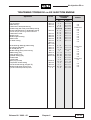
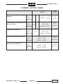
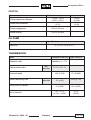
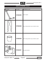
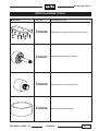
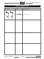
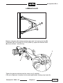
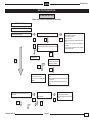
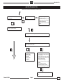
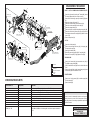
aprilia
QUICK WORKSHOP
HANDBOOK
Electronic air injection
Aprilia Ditech Engine
1095 2
Air-injection 50 cc
CONTENTS
INTRODUCTION
General safety
norms
1
Technical data
2
Oil chart
3
Special engine tools
4
Injection troubleshooting
5
Disassembly/Reassembly
sequence
6
Produced by
Training and Documentation Department
aprilia s.p.a.
Via G. Galilei, 15 - 30033 Noale (VE) - Italy
Tel. +39 - 041 55829111
Fax + 39 - 041 441054
www.aprilia.com
Produced and printed by
Studio Gallo Design srl
Via Mogno,34/1
35012 Camposampiero (PD)
tel. 049 - 9303475
fax. 049 - 9317954
Italy
www.stgallo.it
e-mail: [email protected]
Release 00 / 2002 - 09
- This manual contains all the essential information for
carrying out routine vehicle procedures.
- The information and diagrams in the manual are upto-date at the time of publication.
- This publication is intended for use by Aprilia dealers
and their trained mechanics. A large number of
procedures do not require explanation and therefore
have been omitted. It has not been possible to give
detailed mechanical data for every procedure. All personnel consulting this manual must therefore possess
the basis skills of a mechanic and be thoroughly familiar
with the most common motor cycle repair procedures.
Without these skills and the necessary familiarity any
repair or routine maintenance operation may be
ineffective or even dangerous.
Given the fact that it is not possible to provide detailed
descriptions of all procedures, special care must be
taken for whatever repair or maintenance work is done,
in order to prevent damage to the vehicle and injury to
persons.
In order to provide the best level of customer
satisfaction, Aprilia s.p.a. constantly improves its
products and relevant documentation. All important
technical changes and alterations to procedures are
notified to all Aprilia dealers, branches and points of
sale throughout the world. All changes will be included
in later editions of this manual.
If you have any doubts or queries about the procedures
described in this manual, please contact the Aprilia
Training and Documentation Department, who will be
pleased to give you all the information and explanations
you require, and to bring you up-to-date with any
changes.
For further information see:
- SPARE PARTS CATALOGUE no.
5601
Without alteration to the basic features of its models
as described and illustrated in this manual, Aprilia
s.p.a. may carry out modifications to any of the models
without notice.
Unauthorized electronic retrieval or reproduction of any
part of this manual is unlawful in all countries. Products
or services manufactured or provided by third parties
are quoted merely as examples and do not constitute
a recommendation; Aprilia s.p.a. is not liable for the
performance or use of such products and services.
First edition. September 2002.
Chapter.1
01 / 01
Air-injection 50 cc
GENERAL SAFETY NORMS
WASTE TRANSMISSION OIL
CARBON MONOXIDE
DANGER
If the engine must be switched on to carry out certain
operations make sure the room is well ventilated or
open to the outside. Never switch on the engine in a
closed room, unless there is a smoke and fume removal
system installed
and the operating.
Use latex gloves for maintenance operations
involving contact with oil. If left in contact with the
skin for long periods, used engine oil can cause
skin cancer. Although this is unlikely, unless
handled every day, wash your hands with soap and
water after handling used engine oil.
KEEP OUT OF THE REACH OF CHILDREN
DANGER
Exhaust fumes contain carbon monoxide, a
poisonous gas which make cause loss of
consciousness and can be lethal.
Switch on the engine only in an open space or in a
closed room if fitted with a fully operating smoke and
fume removal system.
GENERAL PRECAUTIONS AND INFORMATION
FUEL
Do not carry out any operation in the presence of
naked flames.
Before starting any maintenance or inspection
operation, switch off the engine and remove the
ignition key. Wait for the engine and exhaust
system to cool down. Place the motor cycle, if
possible, in a raised position on a level, even
surface. Take special care of heated parts (engine
and the exhaust) in order to avoid burns.
The vehicle is made with parts which cannot be
swallowed. Do not bite, chew, suck or otherwise
attempt to carry out operations using the teeth or
mouth.
Unless otherwise specified, to reassemble parts,
reverse the order for disassembly operations.
Some operations may involve disassembling parts
previously disassembled for other operations to
be carried out. Consult the various pages of the
manual where each operation is described in order
to avoid unnecessary work. Never use fuel as a
solvent for cleaning the vehicle.
If welding operations are to be carried out,
disconnect the negative pole (-) of the battery and
take special care with all electrical components
used for the injection system.
If more than one person is working on the vehicle
make sure both are in a safe position whatever the
work being done.
Make sure the room is well ventilated. Extinguish all
cigarettes, keep fuel containers away from flames and
possible sources of sparks.
DANGER
Fuel is highly flammable and may explode.
Take special care to check the air and fuel injection
plant hoses; the operating pressure should not
exceed about 750 KPa (7.5 bar).
Any fuel hoses which are cut or cracked should be
replaced.
KEEP OUT OF THE REACH OF CHILDREN
HIGH TEMPERATURE COMPONENTS
DANGER
The engine and parts of the exhaust system reach
very high temperatures and remain hot for a certain
period after switching off the engine. Handle these
components only after putting on protective gloves
or waiting for the engine and parts to fully cool
down.
Release 00 / 2002 - 09
For repair and disassembly and reassembly operations
follow the instructions.
DANGER
Chapter.1
01 / 02
Air-injection 50 cc
BEFORE DISASSEMBLY
- Remove dirt, mud, dust and foreign bodies from the
vehicle before disassembling the components.
- Use all the tools specifically designed for the vehicle.
DISASSEMBLY
- Before separating pipes or wires etc. (joints and
junctions) mark each part with a unique marking.
Each piece should be clearly marked for reassembly
purposes.
-Clean and wash the disassembled components with
close to non-inflammable detergent.
-Keep paired parts together, because normal wear and
tear create a natural pairing. In some cases, where
one part is replaced the other must also be replaced.
Keep away from sources of heat.
- Lightly smear the edges of oil seals with lithium based
grease.
- Refit the oil seals and bearings with the trademark or
manufacturer’s serial number facing outwards (so it
is visible).
- Grease the bearings fully before fitting.
- Check that all components have been reassembled
properly.
After a maintenance or repair operation, carry out
preliminary checks and commission the vehicle on
private property or in a low traffic area.
REASSEMBLY
DANGER
Never re-use a snap ring. If removed, replace it with
a new ring. If a new ring is fitted, do not stretch
more than necessary when fitting it to the shaft.
Afterwards, check that the ring is properly fitted to
the housing.
Do not clean bearings with compressed air.
IMPORTANT Bearings must rotate freely, without
sticking or noise. Replace if necessary.
- Use only ORIGINAL Aprilia SPARE PARTS.
- Stick to the oil chart and recommended wearing parts.
- Wherever possible, lubricate parts before
reassembling them.
- When tightening screws and nuts begin with the
largest diameters, or inner nuts and screws, and
tighten diagonally. Tighten each before finally
tightening to the specified torque.
- Always replace gaskets, gasket rings, snap rings, Orings and split pins with new ones.
- Clean all joint surfaces, oil seal edges and gaskets
before reassembling.
Release 00 / 2002 - 09
Chapter.1
01 / 03
Air-injection 50 cc
TECHNICAL DATA
ENGINE
Type
Engine type
Number of valves
Number of cylinders
Piston displacement
Bore/Stroke
Corrected compression ratio
Idle rpm
Starter system
Clutch
Gearbox
Lubrication system
Cooling system
air/injection
air-injection with direct petrol injection
mono-cylindrical horizontal
49.38 cm3
41.0 mm / 37.4 mm
rc = 10.7 ± 0.1
1650 ± 50 r/min
electric
centrifuge
automatic stepless variator
Electric oil pump
forced air
TRANSMISSION
automatic stepless
V- belt
minimum for stepless change: 2.9
maximum for stepless change: 0.75
with gears
Variator
Primary
Gears
Secondary
CAPACITY
130 cm3
Transmission oil
THROTTLE BODY
BING
Ø18 mm
Type
Diffuser
FUEL SUPPLY
SIEMENS DEKA
SYNERJECT
Fuel injector
Air injector
IGNITION UNIT
Type of ignition
Ign advance
Inductive
Variable: 20° at 3000 rpm 17° at 7500 rpm.
SPARK PLUG
NGK R CPR8-E
0.55 - 0.65 mm
Standard
Electrode-spark plug distance
ELECTRICAL INSTALLATION
12 V - 4 Ah
7.5 A
12 V - 140 W
Battery
Fuse
Generator (magneto)
Release 00 / 2002 - 09
Chapter.2
02 / 01
Air-injection 50 cc
TIGHTENING TORQUE 50 cc AIR INJECTION ENGINE
Application
Pick-up locking
Stator locking
Transmission steel plate locking
Throttle body (with roller) hose clamp locking
Suction manifold (built-in, hexagonal) locking
Screws and pin securing intake manifold
Transmission cover
Variator cover
Bendix support locking
Starter motor
L/r carter locking
Wheel bearing retaining plate locking
Oil load plug (flanged)
Oil unload (Ch. 8)
Variator sliding pulley cover locking
Head locking (nut)
Clutch locking (nut)
Flywheel locking (nut)
Exhaust stud
Cylinder stud
Spark plug (thread)
Compressor screw locking
Fuel rail screw locking (flanged TE)
Variator fixed pulley locking (nut)
Cylinder head temperature probe
Release 00 / 2002 - 09
Screw
M5 x 12
M5 x 25
M6 x 12
M6 x 20
M6 x 25
M6 x 25
M6 x 30
M6 x 25
M6 x 55
M6 x 75
M6 x 100
M6 x 16
M8 x 12
M6 x 12
M4 x 8
M6 h=9
M10x1.5
M10x1.25
M10x1.0
M5 x 20
M5 x 25
M12x1.25
6-9
Chapter.2
TIGHTENING
TORQUE
Sealant
Nm
Kgm
4-6
4-6
8 - 12
end stop
8 - 12
9 - 11
8 - 12
8 - 12
8 - 12
8 - 12
8 - 12
0.4 - 0.6
0.4 - 0.6
0.8 - 1.2
end stop
0.8 - 1.2
0.9 - 1.1
0.8 - 1.2
0.8 - 1.2
0.8 - 1.2
0.8 - 1.2
0.8 - 1.2
not
not
Loctite 270
not
not
not
not
not
not
not
not
6 - 10
10 - 14
5-6
2
11 - 13
45 - 55
35 - 45
4-5
4-5
13 - 15
4-5
6-7
35 - 45
6-9
0.6 - 1.0
1.0 - 1.4
0.5 - 0.6
0.2
1.1 - 1.3
4.5 - 5.5
3.5 - 4.5
0.4 - 0.5
0.4 - 0.5
1.3 - 1.5
0.4 - 0.5
0.6 - 0.7
3.5 - 4.5
0.6 - 0.9
Loctite 243
not
not
not
not
not
not
Loctite 270
not
/
not
not
not
02/ 02
Air-injection 50 cc
TECHNICAL DATA
CYLINDER + PISTON + RINGS
Item:
Piston to cylinder
clearance
Piston diam.
Standard: mm (in)
Airinjection
0.028-0.040
(0.0011-0.0016)
40.966-40.972
(*)
(1.6128-1.6131)
Selection B 40.972-40.978
(*)
(1.6131-1.6133)
Air- Selection C 40.978-40.984
injection
(*)
(1.6133-1.6135)
Selection A
Limit: mm
(in)
0.100
(0.0039)
40.912
(1.6107)
40.918
(1.6109)
40.924
(1.6112)
Measure 18 mm (0.7) from
the outer edge
Cylinder bore
41.000-41.006
(1.6141-1.6144)
Selection B
41.006-41.012
(1.6144-1.6146)
Airinjection Selection C 41.012-41.018
(1.6146-1.6149)
Selection A
41.050
(1.6161)
41.056
(1.6164)
41.066
(1.6168)
Measure 15 mm (0.59) from
the outer edge
Cylinder distortion
0.005
(0.0002)
0.03
(0.0012)
Cylinder head distortion
0.02
(0.0008)
0.05
(0.0020)
(*) N.B. During disassembly selections A,B, C may not be visible. In this case, refer to limit
values.
Release 00 / 2002 - 09
Chapter.2
02 / 03
Air-injection 50 cc
CYLINDER + PISTON + RINGS
Item:
Port at the end of the unassembled
segment
Port at the end of the segment fitted
into the cylinder
Segment/slot clearance
Piston pin housing bore on piston
Piston pin outer diameter
Release 00 / 2002 - 09
Standard:
mm (in)
Air1°-2°
injection
T
Air1°-2°
injection
T
Airinjection
1°-2°
Limit:
mm (in)
4.5
(0.18)
3.6
(0.14)
0.25 - 0.40
(0.0098 - 0.0157)
0.70
(0.027)
0.036 - 0.076
(0.0014 - 0.0030)
-
Approx.
Airinjection
12.002 - 12.010
(0.4725 - 0.4728)
12.030
(0.4736)
Airinjection
11.996 - 12.000
(0.4723 - 0.4724)
11.980
(0.4717)
Chapter.2
02 / 04
Air-injection 50 cc
CONROD + CRANKSHAFT
Item:
Connecting rod small end diameter
Width from crank arm to arm (A)
Misalignment limit (C)
Side clearance of connecting rod big
end (D)
Standard:
mm (in)
Limite:
mm (in)
Airinjection
16.003 - 16.011
(0.6300 - 0.6304) 36.0 ± 0.05
16.040
(0.6315)
Airinjection
37.95 - 38.10
(1.494 - 1.5)
-
Measured between two opposite points
Airinjection
0.15 - 0.75
(0.0059 - 0.029)
0.03
(0.001)
-
Standard crank width
Release 00 / 2002 - 09
Chapter.2
02 / 05
Air-injection 50 cc
CLUTCH
Item:
Standard: mm (in)
Clutch shoe thickness
110.00 - 110.15
(4.331 - 4.337)
3.0
(0.12)
Limit:mm (in)
110.50
(4.350)
2.0
(0.08)
Clutch engagement
3200 ± 200 rpm
-
Clutch lock-up
6700 ± 300 rpm
-
Clutch wheel inner diameter
OIL PUMP
Item:
Specification:
Ri = 26.3 ± 2.6 Ω a 20° C
Inner coil
TRANSMISSION
Item:
Standard: mm (in)
Reduction ratio
Variable 2.9 - 0.75
-
51/15 x 67 x 14
-
18.4 (0.724)
17.4 (0.685)
110 (4.33)
104.5 (4.114)
17 (0.669)
16.5 (0.650)
107 - 107.2
(4.213 - 4.220)
107.5
(4.232)
Final reduction ratio
Airinjection
Drive belt width
Driven face spring free
Airinjection
Guide roller for variator
Drum diameter
Release 00 / 2002 - 09
Chapter.2
Limit: mm (in)
02 / 06
Air-injection 50 cc
OIL CHART
Transmission oil (recommended):
F.C.,SAE 75W - 90 or
GEAR SYNTH, SAE
75W - 90.
Or alternatively branded oils with equivalent or better performance than A.P.I. GL-4.
Mixer oil (recommended):
GREEN HIT 2 or
CITY 2T.
Or alternatively branded oils with equivalent or better performance than ISO-L-ETC++,A.P.I.
TC++
Bearings and other grease points (recommended):
AUTOGREASE MP or
GREASE 30
Or alternatively branded grease for revolving bearings with temperature range of -30 °C
to+140 °C, dripping point 150 °C + 230 °C, with high protection and anti corrosion properties,
good resistance to water and oxidation.
Release 00 / 2002 - 09
Chapter.3
03 / 01
Air-injection 50 cc
SPECIAL ENGINE TOOLS
UK Illustration
Release 00 / 2002 - 09
Tool code
Name/function or use
8140229
Engine support.
8140429
Tool for fitting the teflon ring onto the air injector.
8140430
Tool for fitting the teflon ring onto the air injector.
8140431
Air injector extractor.
Chapter.4
04 / 01
Air-injection 50 cc
SPECIAL ENGINE TOOLS
UK Illustration
Release 00 / 2002 - 09
Tool code
Name/function or use
8140228
Adapter plate for flywheel and crankcase extraction.
8140227
Reduction gear for bearing assembly.
8140225
Reduction gear for crankcase traction.
8140226
Spacer for crankcase centering.
Chapter.4
04 / 02
Air-injection 50 cc
SPECIAL ENGINE TOOLS
UK Illustration
Tool code
Name/function or use
8140488
Release 00 / 2002 - 09
Fuel-air pressure gauge.
Chapter.4
04 / 03
Air-injection 50 cc
LAMINAR VALVE
A
B
Measure clearance (A) between laminar valve and its housing and size (B).
If clearance (A) is in excess of 0.2 mm (0.008 in), replace the laminar valve.
(B) size is at least 1 mm (0.04 in).
1
2
Tighten the gas-wire adjuster and the return-nut (1) carefully.
If the nut is tightened to quickly, the threaded pawl plastic housing may break (2).
Release 00 / 2002 - 09
Chapter.4
04 / 04
aprilia
Air-injection 50 cc
INJECTION TROUBLESHOOTING
TROUBLESHOOTING SHAFT
(DOUBLE CHECK THE MALFUNCTION BEFORE REPLACING ANY PART)
FUNCTIONAL PHASE
1 - Turn the key to the “ON” position
When the start button is pressed, does the engine turn over?
2 - Does the control LED stay on?
NO
YES
NO
YES
With the key in the “ON” position, is there power (12 Volt)
between the two terminals of the injection control connector
led?
-
Make sure the battery is charged
Check the battery terminals
Check the 15 A fuse
Make sure the fuse connector is properly inserted into its
housing
- Check between the 15 A connector and the positive pole
of the battery
- See the SR 50 water-cooled (injection relay) workshop
manual to check the wiring
NO
Replace the bulb
Is there power between the red/
black cables of the led and the
negative pole of the battery?
YES
YES
NO
- Check the continuity between the black
wire and the ECU connector
- Check the ECU. See “ECU CONTROL”
- Make sure the led connector and fuse are properly connected.
- Make sure the black wire between the led and CDI connector is continuous
- Check the general electrical wiring (battery, fuses, main
switch)
Turn to the “OFF” then to the “ON” position.
Did the pump work?
3 - After turning the key does the fuel pump run for a
few seconds?
NO
YES
Release 00 / 2002 - 09
NO
- Make sure the battery is charged
- Check the battery connections
- Check the voltage at the pump connector
ends
YES
Chapter.5
05/ 01
aprilia
Air-injection 50 cc
INJECTION TROUBLESHOOTING
(DOUBLE CHECK THE MALFUNCTION BEFORE REPLACING ANY PART)
If the starter motor does not start or
turns slowly
4 - Does the starter motor work properly when you press
the starter button?
NO
YES
- Make sure the battery is charged
- Check battery connections
- Check the electric plant against the
workshop drawing for the SR 50 watercooled model (starter motor)
- (Check the earth connection to the starter
motor)
5 - Does the engine start up normally?
NO
Engine flooded: open the throttle crank engine for 10 seconds, then re-start.
Make sure the spark plug is clean; clean or replace if necessary
Make sure it produces a spark on ignition.
NO
YES
-
YES
General diagnostics with Game-boy
Check battery voltage
Replace the spark plug
Check Plug lead
Check the ECU. See
“ECU CONTROL”
Check mechanical parts
- Is the compression ratio right? (piston rings,
piston and cylinder)
- Check the Teflon gasket for the air injector to
see if there are any traces of carbon above the
teflon ring and injector casing
- Does the engine sound strange?
- Are the oil guards and bearings in good
condition?
- Has the reed pack been damaged?
- Is the petrol filter clogged? Is it in place?
- Has the exhaust been damaged? Is it clogged?
NO
See “AIR/FUEL CIRCUIT PRESSURE CONTROL PROCEDURE”
Release 00 / 2002 - 09
Chapter.5
05 / 02
aprilia
Air-injection 50 cc
INJECTION TROUBLESHOOTING
(DOUBLE CHECK THE MALFUNCTION BEFORE REPLACING ANY PART)
Has the pre-delivery procedure been followed for a new vehicle?
6 - Does the engine idle normally?
NO
1- Prime the petrol pump (each time it is replaced) by:
a) switching to “ON”
b) during the 5 seconds that the petrol pump is working press and release the tank/
pump hose repeatedly
c) switch to “OFF” as soon as the petrol pump stops running
d) switch back to “ON”
e) repeat the sequence 8-10 times.
2- Check the spark plug. It may be covered with oil and need cleaning. This will improve
engine performance. Stay on high revs for about 5 minutes.
YES
YES
-
General diagnostics with Game-boy
Check battery voltage
Replace the spark plug
Check Plug lead
Check the ECU. See
“ECU CONTROL”
Check mechanical parts
- Is the compression ratio right? (piston rings,
piston and cylinder)
- Check the Teflon gasket for the air injector to
see if there are any traces of carbon above the
teflon ring and injector casing
- Does the engine sound strange?
- Are the oil guards and bearings in good
condition?
- Has the reed pack been damaged?
- Is the petrol filter clogged? Is it in place?
- Has the exhaust been damaged? Is it clogged?
NO
See “AIR/FUEL CIRCUIT PRESSURE CONTROL PROCEDURE”
Release 00 / 2002 - 09
Chapter.5
05 / 03
aprilia
Air-injection 50 cc
INJECTION TROUBLESHOOTING
(DOUBLE CHECK THE MALFUNCTION BEFORE REPLACING ANY PART)
7 - Does the vehicle accelerate normally (minimum
acceleration)?
NO
YES
- General check-up with Game-Boy and
reset errors (butterfly valve at “O” if
required)
- Check the battery voltage
- Replace the spark plug
- Check Plug lead
- Check the pick-up wiring
- Check ECU. See
“ECU CONTROL”
- Is the variator working properly?
NO
Check mechanical parts
- Are all transmission parts (clutch, belt, rollers, variator) working
properly?
- Is the compression ratio right? (piston rings, piston and
cylinder)
- Check the Teflon gasket for the air injector to see if there are
any traces of carbon above the teflon ring and injector casing
- Does the engine sound strange?
- Are the oil guards and bearings in good condition?
- Has the reed pack been damaged?
- Is the petrol filter clogged? Is it in place?
- Has the exhaust been damaged? Is it clogged?
NO
YES
YES
See “AIR/FUEL CIRCUIT PRESSURE CONTROL PROCEDURE”
8 - Does the vehicle accelerate normally (maximum
acceleration)?
NO
YES
- General check-up with Game-Boy and
reset errors (butterfly valve at “O” if
required)
- Check the battery voltage
- Replace the spark plug
- Check Plug lead
- Check the pick-up wiring
- Check ECU. See
“ECU CONTROL”
- Is the variator working properly?
NO
Check mechanical parts
- Are all transmission parts (belt, variator) in good condition?
- Is the compression ratio right? (piston rings, piston and
cylinder)
- Check the Teflon gasket for the air injector to see if there are
any traces of carbon above the teflon ring and injector casing
- Does the engine sound strange?
- Are the oil guards and bearings in good condition?
- Has the reed pack been damaged?
- Is the petrol filter clogged? Is it in place?
- Has the exhaust been damaged? Is it clogged?
NO
YES
YES
See “AIR/FUEL CIRCUIT PRESSURE CONTROL PROCEDURE”
Release 00 / 2002 - 09
Chapter.5
05 / 04
aprilia
Air-injection 50 cc
INJECTION TROUBLESHOOTING
(DOUBLE CHECK THE MALFUNCTION BEFORE REPLACING ANY PART)
9 - Half-open the throttle: does the vehicle maintain speed?
NO
YES
- General check-up with Game-Boy and
reset errors (butterfly valve at “O” if
required)
- Check the battery voltage
- Replace the spark plug
- Check Plug lead
- Check the pick-up wiring
- Check ECU. See
“ECU CONTROL”
- Is the variator working properly?
NO
Check mechanical parts
- Are all transmission parts (belt, variator) working properly?
- Is the compression ratio right? (piston rings, piston and cylinder)
- Check the Teflon gasket for the air injector to see if there are
any traces of carbon above the teflon ring and injector casing
- Does the engine sound strange?
- Are the oil guards and bearings in good condition?
- Has the reed pack been damaged?
- Is the petrol filter clogged? Is it in place?
- Has the exhaust been damaged? Is it clogged?
NO
YES
YES
See “AIR/FUEL CIRCUIT PRESSURE CONTROL PROCEDURE”
10 - Is top speed normal?
NO
-
Is the variator working properly?
General diagnostics by Game-boy
Check the battery voltage
Replace the spark plug
Check Plug lead
Check the pick-up wiring
Check ECU. See
“ECU CONTROL”
NO
Check mechanical parts
- Are all transmission parts (belt, variator) working properly?
- Is the compression ratio right? (piston rings, piston and cylinder)
- Check the Teflon gasket for the air injector to see if there are
any traces of carbon above the teflon ring and injector casing
- Does the engine sound strange?
- Are the oil guards and bearings in good condition?
- Has the reed pack been damaged?
- Is the petrol filter clogged? Is it in place?
- Has the exhaust been damaged? Is it clogged?
YES
NO
YES
YES
See “AIR/FUEL CIRCUIT PRESSURE CONTROL PROCEDURE”
Release 00 / 2002 - 09
Chapter.5
05 / 05
aprilia
Air-injection 50 cc
INJECTION TROUBLESHOOTING
(DOUBLE CHECK THE MALFUNCTION BEFORE REPLACING ANY PART)
11 - Does the engine work properly ticking over at minimum?
NO
-
General diagnostics by Game-boy
Check the battery voltage
Replace the spark plug
Check Plug lead
Check the pick-up wiring
Check ECU. See
“ECU CONTROL”
NO
YES
Check mechanical parts
- Is the compression ratio right? (piston rings,
piston and cylinder)
- Check the Teflon gasket for the air injector to
see if there are any traces of carbon above the
teflon ring and injector casing
- Does the engine sound strange?
- Are the oil guards and bearings in good
condition?
- Has the reed pack been damaged?
- Is the petrol filter clogged? Is it in place?
- Has the exhaust been damaged? Is it clogged?
NO
YES
YES
See “AIR/FUEL CIRCUIT PRESSURE CONTROL PROCEDURE”
12 - Are noise and vibrations normal?
NO
Release 00 / 2002 - 09
Check mechanical parts
- Compression ration (piston rings, piston,
cylinder)
- Unusual engine noise (seizure)
Crankshaft main bearings, crank
case and connecting rods.
Chapter.5
05 / 06
aprilia
Air-injection 50 cc
INJECTION TROUBLESHOOTING
(DOUBLE CHECK THE MALFUNCTION BEFORE REPLACING ANY PART)
CHECKING THE PRESSURE OF THE AIR AND FUEL CIRCUITS
Fit the pressure gauge to the petrol circuit, between fuel pump and fuel rail
To discharge air from the circuit:
- switch to “ON”
- nudge the starter motor so it switches on momentarily
- the pressure of the fuel circuit should be 2.5 ± 2.0 bar
- switch off
- now the pressure gauge can be fitted
Does the starter motor for the pump start
up? Can you hear the characteristic buzz
when you switch on?
Switch to “OFF”
Is the pressure 2.5 bar?
Check the power at the pump connector. If the voltage is
correct, replace the petrol pump.
N.B. After replacing the pump, start up as specified
above (point 6 of Troubleshooting the Injection)
NO
NO
YES
YES
Does the pressure stay at 2.5 ± 2.0 bar?
NO
Check:
- the tank breather
- the petrol filter and tank delivery flange
- the fuel feed hose
- Start up as specified above (point 6 of
Troubleshooting the Injection)
YES
Check the pump pressure blocking the
delivery hose below the pressure gauge.
Is the pressure 7 bar?
N.B. Do not exceed 7.5 bar, or the pump
will be damaged.
YES
Does the pressure stay at
7.5 bar on “OFF”?
Replace the fuel pump
NO
Blocking the delivery hose above the pump,
does the pressure remain?
N.B. Do not exceed 7.5 bar, or the pump
will be damaged.
YES
Check the hoses and replace the Fuel Rail if necessary
NO
NO
YES
Replace the petrol pump
Release 00 / 2002 - 09
Chapter.5
05 / 07
aprilia
Air-injection 50 cc
INJECTION TROUBLESHOOTING
(DOUBLE CHECK THE MALFUNCTION BEFORE REPLACING ANY PART)
During cranking check the maximum
compressor pressure, blocking the delivery
hose between the pressure gauge fuel rail.
Is it above 4 bar?
Attach pressure gauge to air circuit
NO
NO
Check:
- the reed pack
- hoses
- oil seals and bearings
- air injector
- replace air compressor if necessary
YES
If the pressure drops suddenly, check:
- hoses
- replace air compressor if necessary
Does the pressure stay remain?
NO
YES
Repeat cranking without blocking the
hoses.
Is the air pressure above 2 bar?
NO
Check:
- the reed pack
- oil seals
- bearings
- O ring and injector housing
- replace air injector if necessary
PRESSURE VALUES (BAR) FOR THE AIR AND FUEL CIRCUITS
IN OPERATION
AIR CIRCUIT
FUEL CIRCUIT
OFF
2-5
+ 2.5 ± 0.2 bar
MINIMUM
4.2 ÷ 6
+ 2.5 ± 0.2 bar
MAXIMUM
< 6.2
+ 2.5 ± 0.2 bar
N.B. Petrol pressure is above 2.5 bar
Release 00 / 2002 - 09
Chapter.5
05 / 08
aprilia
Air-injection 50 cc
(DOUBLE CHECK THE MALFUNCTION BEFORE REPLACING ANY PART)
INJECTION TROUBLESHOOTING
DESCRIPTION OF FAULTS
FLASHING NUMBER
1
2
3
4
5
6
Overheated engine
Fault in the phonic wheel
FAULT PRIORITY
1
2
ENGINE CHECK
-
-
Twin error of alignment, throttle sensor (TPS)
Error of alignment, primary throttle sensor (TPS)
2
POSSIBLE CAUSE
Damaged thermostat
Check thermostat
Damaged radiator
Check radiator
Damaged hose
Check hose
Inverted pickup wires
Check wiring
Damaged pickup wires
Check the continuity (R=0 Ohm) between the transducer and ECU (blue wire – white wire - blue/yellow
wire –white/yellow wire). Check opening of the circuit
(R=infinite) between the pickup and earth
Connectors
Check connectors
Transducers
Check resistance (R=385 +/- 20% Ohm) between the
positive and negative poles of the pickup
Throttle control sealing screw out of place
Check the end screw (which shouldn’t be tampered
with)
Throttle wire improperly set (on the handlebar)
Adjust throttle cable
Inverted throttle sensor connector wires
Check connector wires
Connectors
Check connectors
Damaged wires
Check continuity (R=0 Ohm) between the sensor and
ECU (yellow/brown wire - pink wire - white wire - yellow
wire)
Damaged throttle sensor
Replace throttle body
2
Inverted throttle sensor wiring
Check sensor wiring
Connectors
Check connectors
Damaged wires
Check the continuity (R=0 Ohm) between the sensor
and ECU (brown/yellow wire - pink wire - white wire yellow wire)
Sensor races worn
Replace throttle body
Water in the sensor
Remove traces of water and try again. If necessary,
replace the butterfly casing.
Damaged throttle sensor
Replace throttle body
7
8
Secondary throttle sensor (TPS) fault
Twin fault, throttle sensor (TPS)
Release 00 / 2002 - 09
2
1
CHECKS AND REMEDIES
-
Error of alignment, secondary throttle sensor
(TPS)
Primary throttle sensor (TPS) fault
TABLE OF FAULT CODES
Set ticking over speed
Chapter.5
05 / 09
aprilia
Air-injection 50 cc
(DOUBLE CHECK THE MALFUNCTION BEFORE REPLACING ANY PART)
DESCRIPTION OF FAULTS
FLASHING NUMBER
FAULT PRIORITY
ENGINE CHECK
POSSIBLE CAUSE
Battery voltage too low
9
10
11
Inadequate battery voltage or ECU disconnected
Low voltage
Faulty oil pump
Air injector fault
1
1
2
Check the battery charge. Check and restore battery
connections if necessary.
Red/brown wire connector 15 wire to the ECU not connected or connected to earth
Check the continuity (R=0 Ohm) of the red/brown wire.
Voltage regulation wires and/or connectors not wired
up
Check the wires/connectors (see SR 50 WATER HANDBOOK)
Wires and/or connectors of the injector system relay
not connected
Check connectors. Fit the relay between the blue wire
and red/black wire. If the relay closes, check the continuity (R=0 Ohm) between the red/brown wire and orange wire. If the values are correct: check the general
feed plant (battery, fuse, main switch).
Magnet flywheel
Check the magnet flywheel (see SR 50 WATER HANDBOOK)
Connectors
Check connectors
Damaged wires
Check the continuity (R=0 Ohm) of the brown wire between the pump and ECU. Check the voltage (12V)
between the red/black wire and negative battery pole.
Control the general electrical feed plant (battery, fuse,
main switch)
Pompa dell'olio danneggiata
Check the resistance value of the oil pump (26.3 Ohm
at 25°C) between the positive and negative pole.
Damaged ECU
See ECU CONTROL
Connectors
Check connectors
Damaged wires
Check the continuity (R=0 Ohm) of the white/red wire
between the air injector and ECU. Check the voltage
(12V) between the red/black wire and the negative pole
of the battery.
Damaged air injector
Check the resistance inside the air injector between
the negative and positive poles (R= 1.3 Ohm)
-
-
-
Damaged injection plant relay
Damaged ECU
Release 00 / 2002 - 09
CHECKS AND REMEDIES
Chapter.5
Check connectors. Fit the relay between the red and
blue wire. If the relay closes check the continuity (R=0
Ohm) between the red/brown wire and the orange wire.
If values are correct: check the general feed circuit (battery, fuse, main switch).
See ECU CONTROL
05 / 10
aprilia
Air-injection 50 cc
(DOUBLE CHECK THE MALFUNCTION BEFORE REPLACING ANY PART)
DESCRIPTION OF FAULTS
FLASHING NUMBER
12
Fuel injector fault
FAULT PRIORITY
2
POSSIBLE CAUSE
ENGINE CHECK
Connectors
Check connectors
Damaged wires
Check the continuity (R=0 Ohm) of the yellow/red wire
between the fuel injector and ECU. Check the voltage
(12V) between the red/black wire and the negative pole
of the battery.
Damaged fuel injector
Check the resistance inside the air injector between
the negative and positive poles (R= 1.8 Ohm)
-
Damaged injection plant relay
13
Ignition system fault
2
-
Fuel pump fault
Release 00 / 2002 - 09
3
-
Check connectors. Fit the relay between the blue and
red/black wires. If the relay closes, check the continuity (R=0 Ohm) between the red/brown wire and orange
wire. If values are correct: check the general feed circuit (battery, fuse, main switch).
Damaged ECU
See ECU CONTROL
Connectors
Check connectors
High voltage wire spark plug / spark plug
Check the spark plug (R= 5 Ohm). Check the continuity of the High Voltage wire of the spark plug.
Damaged wires
Check the continuity (R=0 Ohm) of the white/violet wire
between the High Voltage wire and ECU. Check the
voltage (12V) between the red/black wire and negative
pole of the battery.
Damaged high voltage cable.
Check the general feed circuit (battery, fuse, main
switch).
Damaged injection plant relay
14
CHECKS AND REMEDIES
Check connectors. Fit the relay between the blue and
red/black wires. If the relay closes check the continuity
(R=0 Ohm) between the red/brown wire and orange
wire. If values are correct: check the general feed circuit (battery, fuse, main switch).
Damaged ECU
See ECU CONTROL
Connectors
Check connectors
Damaged wires
Check the continuity (R=0 Ohm) of the green wire between the fuel pump and ECU. Check the voltage (12V)
between the red/black wire and the negative pole of
the battery.
Main switch circuit
Check the general feed circuit (battery, fuse, main
switch).
Damaged fuel pump
Replace the fuel pump
Damaged ECU
See ECU CONTROL
Chapter.5
05 / 11
aprilia
Air-injection 50 cc
(DOUBLE CHECK THE MALFUNCTION BEFORE REPLACING ANY PART)
DESCRIPTION OF FAULTS
FLASHING NUMBER
FAULT PRIORITY
ENGINE CHECK
POSSIBLE CAUSE
Led for rev limit switch (if on, does not indicate a fault)
15
Rev limit switch triggered
2
Maximum speed limit
16
Fault to sensor feed circuit
ECU Low voltage
3
-
17
Variator threshold exceeded
3
Rev limit
18
Temperature sensor fault (feed with current too
low) -
19
Temperature sensor fault (feed with current too
high) -
3
Damaged ECU
See ECU CONTROL
High revs on start-up
Examine the cause of the high revs at start-up
Connectors
Check connectors
Damaged wires
Check the continuity (R=0 Ohm) of the pink wire between the sensor and ECU, and of the green/red wire
between the sensor and ECU.
Damaged temperature sensor
Check the resistance of the temperature sensor:
21430 - 24750 Ohm at 15 °C / 2613 - 2795 Ohm at 25
°C / 99.9 – 106.9 Ohm at 120 °C
Damaged ECU
See ECU CONTROL
-
3
-
Connectors
20
21
Cooling liquid temperature fault
Injection system – faulty bulb
-
3
Temperature reader wires
3
-
2
Set ticking over speed
Check the connection between the temperature sensor and dashboard connection.
Check the voltage (12V) between the green/red wire
and negative pole of the battery. Check the continuity
(R=0 Ohm) of the white/blue wire between the temperature reader and ECU. Check the continuity (R=0 Ohm)
of the pink wire between the temperature sensor and
ECU and of the green/red wire between the temperature reader and ECU.
Damaged temperature reader
Replace the temperature reader
Damaged ECU
See ECU CONTROL
Can be read using external control instruments
ECU Low voltage sensor feed circuit fault
22
CHECKS AND REMEDIES
Damaged ECU
Check the voltage (12V) between the two terminals of
the injection control led connector. If the voltage is normal: replace the injector control led. If there is no voltage reading: check the led connector and/or red/black
wire between the led and ECU.
See ECU CONTROL
CONTROL ECU
1
Check continuity (R=0 Ohm) between the blue wire (PIN no. 1) and the battery negative
3
Check the voltage (12V) between the red/black wire (PIN no. 17) and battery negative
2
Check voltage (12V) between the red/brown wire (PIN no. 15) and battery negative
4
Replace the ECU with one that functions properly.
Release 00 / 2002 - 09
Chapter.5
05 / 12
DISASSEMBLY SEQUENCE
10
V-BELT - CLUTCH - PRIMARY AND SECONDARY PULLEY
10 Nm (1 kgm)
26
N
G
29
25
27
N
28
22
23
37
G
21
24
20
50 Nm (5 kgm)
38
9
50 Nm (5 kgm)
36
35
10 Nm (1 kgm)
2
15
8
17
16
19
18
13
14
3
12
CLUTCH
31
O.C.
G
L
7
31B
1A
6
4
5
N
10 Nm (1 kgm)
50 Nm (5 kgm)
31A
Remove the 8 screws (1) retaining the T sleeves (1A), loosen
the clamp (1B) and remove the variator cover (2).
Remove the 6-sided nut (3), spacer 4), toothed cup (5) spacer
(6).
Remove the primary fixed pulley (7).
Remove the 6-sided nut (8), remove clutch bell (9).
Remove the clutch assembly from the shaft (10).
Remove the trapezoid belt (11).
Remove shim (12) , bush (13) and mobile primary pulley (14).
Remove the three locking screws (15) of the cap (16) and of
mobile pulley and remove the ramp-plate (17) and the six slide
pieces (18).
Remove slide pieces (19).
11
32
1
L
10 Nm (1 kgm)
Remove the 6-sided nut (20).
Remove the centrifugal clutch assy. (21), Limit spring (22),
and spring holder cup (23).
Remove guide dowels (24).
Slide sliding secondary pulley (25) off fixed pulley (26).
Remove the oil seal (27) O-rings (28) and oil seal (29).
30
1B
10 Nm (1 kgm)
TRANSMISSION
G
34
33
34
O.C.
N
OM
O.C.
OBM
G
L
: New item
: Engine oil
: Gearbox oil
: Molybdenum bisulphuroil
: Grease
: Loctite
Component
9
11
18
21
Drum diameter
V-belt
Variator roller
Clutch shoe
22
Limit spring
N.B. 31A - 31B
STARTER PINION
Remove the 2 locking screw (35), the bendix support (36)
and the bushes (37).
Remove bendix (38).
CHECKING WEAR LIMITS
Chart references
Remove the 8 screws (30), the transmission cover (31), O
ring (31A) or paper gasket (31B).
Remove transmission shaft (10) from the variator half-crank
case.
Remove drive shaft (32), double intermediate gear (33) and
related shims (34) from transmission cover.
Wear limit
Max. diameter: 107.5 mm (original diameter: 107 - 107.2 mm)
Min. width: 17.4 mm (original width: 18.4 mm)
Outer diameter: 16.5 (original diameter: 17 mm)
Min. thickness: 1 mm (original thickness: 1.8 - 2 mm) measured at the centre of the
friction area
Min. length: 105 mm (original length: 110 mm)
Items 31A and 31B are not interchangeable: each has a separate transmission
cover.
REASSEMBLY
Reverse the order of disassembly instructions, making sure
tightening torques are correct, and all components requiring
grease are greased or, if necessary, replaced with components
specified in the table.
RELEASE 00 2002 - 09 AIR INJECTION
TRANSMISSION
Chap.6
TABLE 01
N
OM
O.C.
OBM
G
L
3
1
: New item
: Engine oil
: Gearbox oil
: Molybdenum bisulphuroil
: Grease
: Loctite
8
6
DISASSEMBLY SEQUENCE
COOLING UNIT
Remove the 4 screws (1) and aeration cover (2).
Remove the 2 screws (3) and fan conveyor (4).
Remove the 3 screws (5), retain the T sleeves (6) and
remove the fan (7).
Remove the 3 screws (8) and the base of the fan (9).
5
6
C.A. GENERATOR
1
40 Nm (4 kgm)
11
2
12
8
5 Nm (0.5 kgm)
3
14
5
15
5 Nm (0.5 kgm)
6
17
9
4
Disconnect connectors (10).
Remove the rotor nut (11) without losing the washer (12).
Remove rotor (13).
Remove the two locking screws of stator plate (14) and pickup (15).
Remove stator (16) and pick-up (17).
7
13
16
10
CHECKING WEAR LIMITS
Chart references
Component
16
Stator
17
Pick-up
Rated values
Yellow-Orange wire R = 265 Ohm ± 20 % at 20° C
Orange-Earth wire R = 395 Ohm ± 20 % at 20° C
Blue-Brown wire R = 385 Ohm ± 20 % at 20° C
REASSEMBLY
Reverse the order of disassembly instructions, making sure
tightening torques are correct, and all components requiring
grease are greased or, if necessary, replaced with components
specified in the table.
RELEASE 00 2002 - 09 AIR INJECTION
GENERATOR
Chap.6
TABLE 02
DISASSEMBLY SEQUENCE
INJECTION UNIT
Empty the fuel tank
Disconnect the wires
Remove the 2 flanged screws (1).
Remove the input valve (2).
Remove the air injector using the proper tool (3).
Slide off the O rings (4), (5).
6
DANGER
3
If connector hoses are removed (after removing the
clamps), be very careful when refitting the high pressure
hose (6) (maximum pressure 8-10 bar).
5
2
4
1
6-7 Nm (0.6-0.7 kgm)
N
OM
O.C.
OBM
G
L
: New item
: Engine oil
: Gearbox oil
: Molybdenum bisulphuroil
: Grease
: Loctite
CHECKING WEAR LIMITS
Chart references
Component
Rated values
REASSEMBLY
Reverse the order of disassembly instructions, making sure
tightening torques are correct, and all components requiring
grease are greased or, if necessary, replaced with components
specified in the table.
RELEASE 00 2002 - 09 AIR INJECTION
INJECTION UNIT
Chap.6
TABLE 03
DISASSEMBLY SEQUENCE
17
17
22
HEAD - CYLINDER - PISTON
23
18
Remove the 2 screws (1), retain the 2 T sleeves (2).
Remove the 2 screws (3).
Remove the LH cylinder cover (4) and RH cover (5).
Remove spark plug (6) and thermostat (7).
Remove the four tightening head nuts (8).
Remove head (9), head gasket (10), cylinder (11), base gas
ket (12).
Remove the pin stop (13).
Slide out pin (14) and piston (15).
Remove rings (16).
24
21
5 Nm (0.5 kgm)
5
OM
19
N
OM
20
14
13
11
7
N
6-9 Nm (0.6-0.9 kgm)
Remove the 4 screws (17) securing the manifold and retain
the washers (18).
Slide off the mill pack (19) and gaskets (20).
Remove the throttle body hose clamp (21).
Remove the throttle body (22).
Disconnect the oil pump hose (23).
Do not lose the intake manifold (24).
16
12
2
5 Nm (0.5 kgm)
3
L
9
THROTTLE BODY - LAMINAR PACK
15
1
10
8
11-13 Nm (1.1-1.3 kgm)
2
6
4
3
N
OM
O.C.
OBM
G
L
: New item
: Engine oil
: Gearbox oil
: Molybdenum bisulphuroil
: Grease
: Loctite
CHECKING WEAR LIMITS
Chart references
9
11
14
15
16
19
Component
Head
Cylinder
Piston pin
Piston
Upper ring
Lower ring
Laminar valve
Wear limit
Flatness limit: 0.05 mm
Max bore: 41.066 mm
Min diameter: 40.912 mm
Min diameter: 11.98 mm
Piston-cylinder clearance: 0.100 mm
End space max: 0.7 mm
End space max: 0.7 mm
Valve body - laminar element space: 0.2 mm
REASSEMBLY
Reverse the order of disassembly instructions, making sure
tightening torques are correct, and all components requiring
grease are greased or, if necessary, replaced with components
specified in the table.
RELEASE 00 2002 - 09 AIR INJECTION
HEAT UNIT
Chap.6
TABLE 04
11
13
DISASSEMBLY SEQUENCE
G
4-5 Nm (0.4-0.5 kgm)
1
AIR COMPRESSOR
1
Remove the 4 screws (1) without losing the washers (2).
Remove the compressor (3) from the guard.
Remove the OR (4).
Unscrew the compressor connector (5).
2
G L N
3
10
OM
G
N
OM
COVER AND CRANKCASE
14
15
5
12
G L N
G
6
Remove the six cover screws (6).
Separate the RH half (7) from the LH half (8) of the cover.
Remove the gasket (9).
Remove the crankcase (10) from the RH half.
Remove the RH oil guard (11) and LH oil guard (12).
Remove the RH (13) and LH (14) bearing.
4
N
WARNING
10 Nm (1 kgm)
N.B.: Grease the RH (13) and LH (14) crankshaft main
bearings.
N
9
7
N
: New item
OM
O.C.
OBM
G
L
: Engine oil
: Gearbox oil
: Molybdenum bisulphuroil
: Grease
: Loctite
8
CHECKING WEAR LIMITS
Chart references
10
10
10
15
Component
Crankcase
Crankcase
Crankcase
Connecting rod
Wear limit
Standard width: 37.95 - 38.10 mm
Off-line tolerance 0.03 mm (measured at two opposite points)
Connecting rod head side play: 0.85 mm (original: 0.75 mm)
Max diameter connecting rod foot: 16.04 mm (original: 16.003 - 16.011 mm)
REASSEMBLY
Reverse the order of disassembly instructions, making sure
tightening torques are correct, and all components requiring
grease are greased or, if necessary, replaced with components
specified in the table.
RELEASE 00 2002 - 09 AIR INJECTION
COVER + CRANKCASE
Chap.6
TABLE 05
Produced and printed by Studio Gallo Design srl Via Mogno,34/1 35012 Camposampiero (PD) Italy tel. 049 - 9303475 fax 049 - 9317954 www.stgallo.it e-mail: [email protected]
aprilia part #8140649 - 09/02 - UK