1
Installation Guide
XR500 Series CANADIAn
control Panel
MODEL XR500, XR500N, XR500E
CANADIAN INSTALLATION GUIDE
INDUSTRY CANADA NOTICE
This Class A digital apparatus complies with Canadian ICES-003.
© 2015 Digital Monitoring Products, Inc.
Information furnished by DMP is believed to be accurate and reliable.
This information is subject to change without notice.
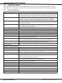
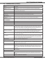
Table of Contents
Product Specifications
1.1
Power Supply..........................................................................1
1.2Communication.......................................................................1
1.3
Panel Zones............................................................................1
1.4
Keypad Bus.............................................................................1
1.5LX-Bus™.................................................................................1
1.6Outputs..................................................................................1
1.7
Enclosure Specifications...........................................................1
Panel Features
2.1Description..............................................................................2
2.2
Zone Expansion.......................................................................2
2.3
Output Expansion....................................................................2
2.4
Central Station Communication.................................................2
2.5
Encrypted Communications (XR500N/XR500E only)....................2
2.6
Caution Notes.........................................................................2
2.7
Compliance Instructions...........................................................2
System Components
3.1Description..............................................................................3
3.2
Wiring Diagram.......................................................................3
3.3
Lightning Protection.................................................................4
3.4
Accessory Devices...................................................................4
3.4
Accessory Devices (continued)..................................................5
Installation
4.1
4.2
4.3
4.4
Mounting the Enclosure............................................................6
Mounting Keypads and Zone Expansion Modules........................7
Connecting LX-Bus and Keypad Bus Devices..............................8
Wireless Keypad Association.....................................................8
Primary Power Supply
5.1
5.2
5.3
AC Terminals 1 and 2...............................................................8
Transformer Types...................................................................8
J12 3-Pin Header for Transformer Types....................................8
Secondary Power Supply
6.1
Battery Terminals 3 and 4........................................................9
6.2
Earth Ground (GND)................................................................9
6.3
Battery Only Restart................................................................9
6.4
Battery Replacement Period.....................................................9
6.5Discharge/Recharge.................................................................9
6.6
Battery Supervision..................................................................9
6.7
Battery Cutoff..........................................................................9
6.8
XR500 Series Canadian Power Requirements...........................10
6.9
Standby Battery Selection......................................................12
Bell Output
7.1
Terminals 5 and 6..................................................................13
Keypad Bus
8.1Description............................................................................13
8.2
Terminal 7 - RED...................................................................13
8.4
Terminal 9 - GREEN...............................................................13
8.5
Terminal 10 - BLACK..............................................................13
8.6
J8 Programming Connection...................................................13
8.7
OVC LED...............................................................................13
XR500 Series Canadian Installation Guide
Digital Monitoring Products
i
Table of Contents
Smoke and Glassbreak Detector Output
9.1
9.2
Terminals 11 and 12..............................................................13
Current Rating.......................................................................13
Protection Zones
10.1
10.2
10.3
10.4
10.5
Terminals 13–24....................................................................14
Operational Parameters..........................................................14
Dual EOL..............................................................................14
Zone Response Time..............................................................14
Keyswitch Arming Zone..........................................................14
Powered Zones for 2-Wire Smoke Detectors
11.1
11.2
Terminals 25–26 and 27–28...................................................15
Compatible 2-Wire Smoke Detector Chart................................16
Dry Contact Relay Outputs
12.1Description............................................................................17
12.2 Contact Rating......................................................................17
12.3 Model 431 Output Harness Wiring...........................................17
Annunciator Outputs
13.1Description............................................................................17
13.2 Model 300 Harness Wiring......................................................17
13.3 Model 860 Relay Module........................................................17
J23 6-Pin Header
14.1Description............................................................................18
J22 LX-Bus Expansion Connector
15.1Description............................................................................18
15.2 J22 LX-Bus Header................................................................18
15.3 LX-Bus Interface Cards...........................................................19
15.4 LX-Bus LEDs..........................................................................19
15.5 OVC LED...............................................................................19
J21 Serial Connector
16.1Description............................................................................19
16.2 Computer Connection to J21..................................................19
16.3 Serial Connector LEDs............................................................19
J1 Ethernet Connector (XR500N/XR500E only)
17.1Description............................................................................20
17.2 Ethernet LEDs.......................................................................20
J3 Telephone RJ Connector
18.1Description............................................................................20
18.2 J10 893A Connector...............................................................20
18.3 Notification...........................................................................20
18.4 Phone Line Monitor................................................................20
Reset and Tamper Headers
19.1
19.2
J16 Reset Header .................................................................21
J4 Tamper Header ................................................................21
Listed Compliance Specifications
20.1Introduction..........................................................................22
Digital Monitoring Products
ii
XR500 Series Canadian Installation Guide
Table of Contents
Burglary Specifications
21.1Introduction..........................................................................22
21.2 Control Outside of Protected Area...........................................22
21.3 Bypass Reports......................................................................22
21.4 System Maintenance..............................................................22
ULC S304-06 Specifications
22.1
22.2
22.3
22.4
22.5
22.6
22.7
For Medium or High Risk Applications:
Level A3 Communication........................................................22
For Very High Risk Applications:
Level A3 Plus P1 Communication............................................22
For Low Risk Applications: Level A1........................................23
For Low Risk Applications: Level P1.........................................23
Dual Protection......................................................................23
Remote Arming.....................................................................23
Zone Expansion.....................................................................23
ULC S559-04 Specifications
23.1 For Fire Communicator Applications........................................23
23.2 Central Station Host Automation................................................23
Recommendations
24.1
ULC Burglary Installation Recommendations............................24
False Alarm Reduction Programmable Options *
25.1
Shipping Defaults and Recommended Programming
for ANSI/SIA CP-01-2010.......................................................25
False Alarm Reduction Programmable Options (continued)
25.2
25.3
25.4
25.5
Call Waiting (ANSI/SIA CP-01-2010).......................................26
Occupied Premise (ANSI/SIA CP-01-2010)...............................26
Entry Delay (ANSI/SIA CP-01-2010)........................................26
Minimum Installation Requirements (ANSI/SIA CP-01-2010).....26
Wiring Diagrams
26.1 Rothenbuhler 5110 High Security Bell Wiring...........................27
26.2 LX-Bus™ Module Connection..................................................28
26.3 Model 860 Relay Module Connection.......................................29
26.4 Dual Zone Protection.............................................................29
26.5 Canadian Fire Communicator for FACP....................................30
26.6 Combination S304 and S559 System.......................................31
26.7 System Sensor 2-Wire Smoke Detectors......................................32
Revisions to This Document
Certifications
XR500 Series Canadian Installation Guide
Digital Monitoring Products
iii
Digital Monitoring Products
iv
XR500 Series Canadian Installation Guide
Introduction
Product Specifications
1.1
Power Supply
Transformer Input:
Model 327-CAN, plug-in — Primary input: 120 Vac, 60 Hz, Secondary output: 16.5 Vac 50 VA
Model FTA7516 ATC Frost from Standex Electronics — Primary input: 120 Vac, 60 Hz,
Secondary output: 16 Vac 75 VA
Standby Battery: 12 Vdc, 1.0 Amps Max. charging current
Models 365, 366, 368, or 369
Replace every 3 to 5 years
Auxiliary:
12 Vdc output at 1.0 Amp Max using Model 327-CAN
Bell Output:
12 Vdc at 1.0 Amp Max using Model 327-CAN
Auxiliary:
12 Vdc output at 1.5 Amp Max using Model FTA7516
Bell Output:
12 Vdc at 1.5 Amp Max using Model FTA7516
All circuits are inherent Power Limited except the red battery wire and AC terminal.
1.2Communication
•Built-in network communication to DMP Model SCS-1R or SCS-VR Receivers (XR500N/XR500E only)
•Built-in encrypted communication to DMP Model SCS-1R Receivers (XR500E only)
•Built-in dialer communication to DMP Model SCS-1R Receivers
•Optional cellular communication to DMP Model SCS-1R or SCS-VR Receivers
•Built-in Contact ID communication to DMP Model SCS-1R Receivers
•Optional 893A Dual Phone Line Module with phone line supervision
•Can operate as a local panel
1.3
Panel Zones
Eight 1k Ohm EOL burglary zones (zones 1 to 8)
Two 3.3k Ohm EOL powered zone with reset (zones 9 and 10)
1.4
Keypad Bus
You can connect up to a total of 16 of the following supervised keypads and expansion modules to the keypad bus:
• Alphanumeric keypads
• Four- and/or single-zone expansion modules
• Single-zone detectors
• Access control modules
• Wireless Keypads (maximum of 4)
1.5LX-Bus™
You can connect the following devices to the LX-Bus™ provided on the panel or by the DMP 481, 462N, and 464-263H
Interface Cards up to the maximum number of LX-Bus™ addresses. See Accessory Devices in section 3.4.
• Sixteen-, eight-, four- and/or single-zone expansion modules • Graphic annunciator modules
• Model 521LX or 521LXT Smoke Detectors with CleanMe
• Relay output expansion modules
• Model 2W-BLX or 2WT-BLX Smoke Detectors
1.6Outputs
The XR500 Series provide two Single Pole, Double Throw (SPDT) relay outputs which require the installation of two
Model 305 relays, each rated 1 Amp at 30 Vdc resistive (power limited sources only). A Model 431 Output Harness is
required to use these outputs.
The XR500 Series panels also provide four open collector outputs rated for 50mA each. The open collector outputs
provide ground connection for a positive voltage source. A Model 300 Output Harness is required to use these
outputs.
1.7
Enclosure Specifications
The XR500 Series panels are shipped in an enclosure with a transformer, End-of-Line resistors, battery leads, user’s
guide, and programming sheets.
Enclosure
Model
Size
Color(s)
Construction (Cold Rolled
Steel)
350
17.5”W x 13.5”H x 3.5”D
Gray (G) or Red (R)
18-Gauge
350A
17.5”W x 13.5”H x 3.75”D
Gray (G)
18-Gauge with 16-Gauge door
341
12.75”W x 6.55”H x 3.15”D
Gray (G)
20-Gauge
352X
14.5”W x 32.0”H x 4.0”D
Gray (G)
16-Gauge
XR500 Series Canadian Installation Guide
Digital Monitoring Products
1
Introduction
Panel Features
2.1Description
The DMP XR500 Series Canadian panel is a versatile 12 Vdc, combined access control, burglary, and fire
communicator panel with battery backup. The XR500 Series provides eight on-board burglary zones and two on-board
12 Vdc Class B powered zones. The powered zones have a reset capability to provide for 2-wire smoke detectors,
relays, or other latching devices. The XR500 Series can communicate to DMP SCS-1R Receivers using digital dialer,
cellular, network, or Contact ID communication.
2.2
Zone Expansion
Up to 574 additional zones are available on the XR500 Series using DMP LCD keypad remote zone capability and zone
expansion modules. The panel keypad data bus supports up to sixteen supervised device addresses with each address
supporting up to four programmable expansion zones.
Up to 500 zones are available using the on board LX-Bus, Model 461 Interface Adaptor with 481, 462N, 462P,
or 464-263H, and any combination of single, four, eight, or 16-zone expansion modules and single-zone LX‑Bus™
detectors.
Note: Do not use shielded wire for LX-Bus or Keypad Bus circuits.
2.3
Output Expansion
In addition to the two SPDT relays and four programmable open collector outputs on the XR500 Series, you can also
connect up to 25 programmable Model 716 Output Expansion Modules to each LX-Bus. These modules can provide an
additional 500 programmable SPDT relays.
The XR500 Series provides 100 Output Schedules you can use for programming the 716 to perform a variety of
annunciation and control functions. You can also assign the 716 outputs to any panel Output Options such as Fire
Alarm, Communication Fail, or Phone Trouble Outputs. Refer to the 716 Installation Guide (LT-0183).
The LX-Bus™ also supports the Model 717 Graphic Annunciator Module. Each 717 module supplies 20 switched ground
outputs that follow the state of their assigned zones.
Note: The 717 supports the first eight Keypad Bus addresses. To follow Keypad Bus addresses nine through 16, install
multiple 716 modules. Refer to the 717 Installation Guide (LT-0235) and 716 Installation Guide (LT‑0183).
2.4
Central Station Communication
You can program the XR500 Series panel for reporting to DMP SCS‑1R or SCS-VR Receivers using digital dialer, cellular,
network, or Contact ID communication. The XR500 Series connects at the premises to a standard RJ31X or RJ38X
telephone jack. Use the DMP 893A Dual Phone Line Module when connecting the XR500 Series panel to two separate
phone lines in fire or burglary applications.
2.5
Encrypted Communications (XR500N/XR500E only)
An XR500E panel communicates using AES encryption. If you currently have an XR500N panel installed, you may
contact DMP Customer Service with the panel serial number. The serial number(s) should be sent in writing via
e-mail or fax. A separate feature key is sent for each panel to activate encrypted communications using the Feature
Upgrade process. Encrypted communication cannot be enabled on a standard XR500 panel. For more information on
the Feature Upgrade process see the XR500 Series Canadian Programming Guide (LT-0679CAN).
2.6
Caution Notes
Throughout this guide you will see caution notes containing information you need to know when installing the panel.
These cautions are indicated with a yield sign. Whenever you see a caution note, make sure you completely read
and understand its information. Failing to follow the caution note can cause damage to the equipment or improper
operation of one or more components in the system. See the example shown below.
2.7
Always ground the panel before applying power to any devices: The XR500 Series must be properly
grounded before connecting any devices or applying power to the panel. Proper grounding protects
against Electrostatic Discharge (ESD) that can damage system components.
Compliance Instructions
For applications that must conform to a local authorities installation standard or a National Recognized Testing
Laboratory certificated system, please see the Listed Compliance Specifications section near the end of this guide for
additional instructions.
Digital Monitoring Products
2
XR500 Series Canadian Installation Guide
Introduction
System Components
3.1Description
The DMP XR500 Series system is made up of an alarm panel with a built-in communicator, an enclosure, battery,
one 16.5 Vac transformer, and keypads. You can use up to sixteen supervised 32-character LCD keypads; network
communications and expansion interface cards; zone and output expansion modules; and initiating and indicating
circuit modules. You can also connect auxiliary devices to the panel’s output relays to expand the basic system
control capability. Combined current requirements of additional modules may require an auxiliary power supply.
Refer to the XR500 Series Power Requirements section in this guide when calculating power requirements.
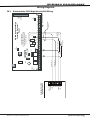
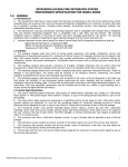
3.2
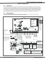
Wiring Diagram
The XR500 Series diagram below shows some of the accessory modules you can connect for use in various
applications. A brief description of each module follows in section 3.4.
s
XR500 Series Canadian
Panel
Form C Relays (J2)
Output Color Code–Model 431 Harness
Output 2 N/O Orange/White
Output 2 Com White/Gray
Output 2 N/C Violet/White
Output 1 N/O Orange
Output 1 Com Gray
Output 1 N/C Violet
J4
Tamper
Link LED
Activity LED
J1 s
Ethernet
K6
J8
PROG
K7
RED
BLACK
SIA CP-01-2010 minimum
system is XR500, listed local
Earth Ground
Bell, and off premise DACT
communication to an SCS-1R
receiver plus listed compatible
keypads as indicated in the
installation guide.
s s
s s
Cold Water
Pipe Earth
Ground 1k
Bell
Ohm
s
s
Bell cutoff time
range is 5 to 99
minutes, non-coded.
s
s
s
Smoke
Detector
ARM
s
14
15 16
s s
s
s
1k
1k
Ohm Ohm
s
17
s
18 19
s
s
1k
1k
Ohm Ohm
s
20
21 22
s s
s
23
s
1k
1k
Ohm Ohm
24 25
s s
27
Zone
9
s
1k
1k
Ohm Ohm
26
s
s
28
Zone
10
s
s
3.3k Ohm
3.3k Ohm
Resistor DMP Resistor DMP
Model
309
Model 309
s = Supervised Circuit
Zone Expander
Model 715
7mA @ 12 VDC
Models 715-8, 715-16
20mA @ 12 VDC
Zone Expander
Model 714
7mA @ 12 VDC
Models 714-8, 714-16
20mA @ 12 VDC
Zone
Expander
Model 711
7mA @ 12
VDC
Zone Expander
(up to 8 zones)
Model 712-8
19mA @ 12
VDC
s
s
s
s
s
s
s
s
3.3k Ohm 3.3k Ohm 3.3k Ohm 3.3k Ohm
s s
s
s
s
s s
s
1k Ohm 1k Ohm 1k Ohm
Use Listed Power Supervision
Relay rated at 12 VDC.
Z7 GND Z8 Z9+ Z9– Z10+ Z10–
Minimum voltage on Auxiliary output to
process Sensor trips is 10.2 VDC.
Auxiliary/Smoke Power
Total current combined from
terminals 7, 11, 25, and 27
1.5 Amp Max 10.2 VDC to 14.0 VDC
s
Zones 9 and 10 and
Model 715 compatibility
identifier: A
Maximum operating
range: 9.7 VDC to
14.0 VDC.
Class B (Style A).
J16
Reset
RED
RED
YELLOW
GREEN
BLACK
s
1k Ohm 1k Ohm 1k Ohm
12 13
s s
s
Keyswitch Arming
can be connected
to any zone.
DISARM
11
Z3 GND Z4 Z5 GND Z6
Zone 2
10
Zone 1
s
9
22 gauge minimum
s
s
s
8
22 gauge minimum
6
BLACK
Bell
s
16 to 18 gauge wire
12 VDC
Maximum AC Wire distance
Minimum cutoff time 15 min. with 16 gauge wire: 70 feet
1.5 Amp Max using FTA7516 with 18 gauge wire: 40 feet
7
22 gauge minimum
5
GREEN
4
22 gauge minimum
3
RED
2
YELLOW
1
s
3
4
5
6
Heat detectors, pull
stations, or any other
contact devices listed
for Fire Protective
Signaling can be
connected to zones
9 and 10.
Outputs 3-6
AC AC +B –B BELL GND RED YEL GRN BLK SMK GND Z1 GND Z2
s
Listed Resistors
1.0k Ohm - DMP Model 311
3.3k Ohm - DMP Model 309
10K Ohm - DMP Model 308
J11
Zone 8
Battery
Start
The plug-in transformer
shall plug into a 120 VAC
60 Hz outlet not controlled
by a switch.
Output 1 OVC Output 2
J2
J10
Zone 5
RS-232
J22
LX-Bus
L
X
Zone 6
Power J23
R
LED
Zone 3
50VA
Rear
Tamper
Annunciator Outputs (J11)
Output Color Code
Output 3
Red
Output 4
Yellow
Output 5
Green
Output 6
Black
s
J21
Zone 4
75VA
Out1 Out2
J12
Zone 7
J3 s
Phone Line
Front and Rear
tamper protection
included with
Model 350A
Attack Resistant
Enclosure.
Front
Tamper
s
WARNING: Incorrect
connections may cause
damage to the unit.
s
1k Ohm
s
1k Ohm
CAUTION: DO NOT USE LOOPED WIRE
UNDER TERMINALS. BREAK WIRE RUN TO
PROVIDE SUPERVISION OF CONNECTIONS.
1k Ohm
Figure 1: XR500 Series Canadian Wiring Diagram
XR500 Series Canadian Installation Guide
Digital Monitoring Products
3
Introduction
3.3
Lightning Protection
Metal Oxide Varistors and Transient Voltage Suppressors help protect against voltage surges on XR500 Series input
and output circuits. Additional surge protection is available by installing the DMP 370 or 370RJ Lightning Suppressors.
3.4
Accessory Devices
Interface Adaptor and Interface Cards
461 Interface Adaptor Card
462N Network Interface Card
462P Printer Interface Card
464-263H Cellular Communicator
Card
481 Expansion Interface Card
Expansion Modules
710 Bus Splitter/Repeater
711 Single Point Zone Expanders
714, 714-8, 714-16 Zone Expanders
712-8 Zone Expander
715, 715-8, 715-16 Zone Expanders
716 Output Expander
717 Graphic Annunciator Module
734, 734N, 734N-WiFi Wiegand
Interface Modules*
Allows you to connect two or more expansion interface cards to the XR500 Series panel.
The 461 is an expansion mother board that plugs into the panel J6 Interface Connector and
is required when using two or more Interface Cards. Use combinations of Interface Cards
for expanding zones, network interfacing, local printing, and connecting wireless devices.
Allows you to connect the XR500 Series to any compatible data network and use its
communication capability in place of standard dial out telephone lines. The 462N also
provides an LX-Bus™ for connecting zone and output expansion modules to the panel.
Allows you to connect the XR500 Series to any compatible serial printer providing the user
with real-time event recording. The 462P also provides an LX-Bus™ for connecting zone and
output expansion modules.
Provides a fully supervised alarm communication path over HSPA + network for XR100/
XR500 Series panels. The 464-263H also provides an LX-Bus™ for connecting zone and
output expansion modules to the panel.
Provides one LX-Bus for connecting up to 100 zone and output expansion modules.
Allows you to increase keypad or LX-Bus™ wiring distance to 2500 feet.
Provides one Class B zone for connecting burglary devices.
Provides Class B zones for connecting burglary and non-powered fire devices.
Provides Class B zones for connecting burglary devices.
Provides 12 Vdc Class B powered zones for connecting smoke detectors, glassbreak
detectors, and other 2- or 4-wire devices.
Provides four Form C relays (SPDT) and four switched grounds (open collector) for use in a
variety of remote annunciation and control applications for use on the LX-Bus only.
Provides 20 zone following annunciator outputs (open collector) for use in a variety of
remote annunciation and control applications for use on the LX-Bus only.
Provides system codeless entry, and arming and disarming using access control readers.
DMP Two-Way Wireless Devices
1100X/1100XH Wireless Receiver*
Supports up to 500 devices in residential or commercial wireless operation.
1100R Repeater*
Provides additional range for wireless devices.
1101 Universal Transmitter*
Provides both internal and external contacts that may be used at the same time to yield
two individual reporting zones from one wireless transmitter.
1102 Universal Transmitter*
Provides an external contact.
1103 Universal Transmitter*
Provides both internal and external contacts that may be used at the same time to yield two
individual reporting zones from one wireless transmitter. Requires EOL resistor for external
contact. Provides Disarm/Disable functionality.
1105 Universal Transmitter*
Provides both internal and external contacts that may be used at the same time to yield
two individual reporting zones from one wireless transmitter.
1107 Micro Window Transmitter*
Provides a wireless window transmitter
1114 Four-Zone Expander*
Provides four wireless zones
1116 Relay Output*
Provides one Form C relay
1117 LED Annunciator*
Provides a visual system status indicator
1118 Remote Indicator Light*
Provides a visual indication of a Panic situation
1119 Door Sounder*
Provides a battery powered sounder
1121 PIR Motion Detector*
Provides motion detection with pet immunity.
1125 PIR Motion Detector*
Provides multiple lens configurations, dual coverage area selection, and sensitivity adjustments.
Digital Monitoring Products
4
XR500 Series Canadian Installation Guide
Introduction
3.4
Accessory Devices (continued)
DMP Two-Way Wireless Devices (continued)
1126C/1126R PIR Motion
Detector*
Ceiling mount motion detector with panel programmable sensitivity and Disarm/Disable
functionality.
1127C/1127W PIR Motion
Detector*
Wall mount motion detector with panel programmable sensitivity and Disarm/Disable
functionality.
1129 Glassbreak Detector*
Detects the shattering of framed glass mounted in an outside wall and provides full-pattern
coverage and false-alarm immunity.
1131 Recessed Contact*
Provides a recessed contact option for door or window applications.
1135/1135DB Wireless Sounder*
Provides a wireless sounder.
1139 Bill Trap *
Provides a silent alarm option for retail and banking cash drawers.
1142BC Two-button Hold-up Belt
Clip Transmitter*
Provides two-button hold-up operation with a belt clip.
1142 Two-button Hold-up
Transmitter*
Provides permanently mounted under-the-counter two-button hold-up operation.
1145-4 (Four-Button) *
1145-2 (Two-Button)*
1145-1 (One‑Button)*
Key Fob transmitters designed to clip onto a key ring or lanyard.
1183-135F Heat Detector
Fixed temperature heat detector
1183-135R Heat Detector
Fixed temperature and rate-of-rise heat detector
1184 Carbon Monoxide Detector*
Carbon Monoxide Detector
Indicating and Initiating Devices
860 Relay Module*
865 Supervised Style W or X
Notification Circuit Module*
Provides dry relay contacts that are programmable and controlled from the DMP panel
annunciator outputs. Includes one Form C (SPDT) relay rated 1 Amp @ 30 Vdc. Sockets are
provided to allow the addition of three Model 305 plug-in relays. These relays can be used
for electrical isolation between the alarm panel and another system or switching 5, 12, or 24
Volts to control various functions within a building or around its perimeter.
Provides supervised alarm current when using the XR500 Series panel bell output and up to
5 Amps at 12 or 24 Vdc when using a listed auxiliary power supply. The 865 can supervise
2-wire or 4-wire style circuits for opens and shorts with individual LED annunciation.
866 Style W Notification Circuit
Module *
Provides supervised alarm current using the XR500 Series panel bell output and up to 5 Amps
at 12 or 24 Vdc when using a listed auxiliary power supply. The 866 can supervise 2-wire Style
W circuits for opens and shorts.
867 Style W LX-Bus Notification
Circuit Module*
Provides supervised alarm current using the XR500 Series panel bell output and up to 5 Amps
at 12 or 24 Vdc when using a listed auxiliary power supply. The 867 connects to the XR500
Series panel LX-Bus™ and provides one 2-wire Style W notification circuit for open and short
conditions. Individual Bell Relay addresses Bell Ring styles.
869 Dual Class A Style D
Initiating Module*
Provides two Class A, Style D, 4-wire initiating zones for connecting waterflow switches and
other non‑powered fire and burglary devices.
Accessory Modules and Keypads
893A Dual Phone Line Module*
Allows you to supervise two standard phone lines connected to an XR500 Series panel. The
893A module monitors the main and backup phone lines for a sustained voltage drop and
alerts users when the phone line is bad.
ePAD™ Virtual Keypads*
Allows users to control the security system from any computer using the Internet.
LCD keypads
Allows you to control the panel from various remote locations. Connect up to sixteen Model
630F Remote Fire Command Center, Model 7060, 7063, 7070, 7073, 7160, 7163, 7170, 7173
Thinline™ keypads, 7060A, 7063A, 7070A, 7073A Aqualite™ keypads, the 7760 Clear Touch™
keypad, or the 7872, 7873 Graphic Touchscreen keypads to the keypad bus using terminals 7,
8, 9, and 10.
Allows you to control the panel from various remote locations. Connect up to four 9060/9063
Wireless Keypads.
9000 Series Wireless Keypads*
Addressable Smoke Detectors
521LX, 521LXT*
Single-zone, addressable conventional smoke, smoke/heat detectors that connect to the
LX-Bus. Includes remote maintenance reporting, drift compensation, and multi-criteria
detection.
2W-BLX, 2WT-BLX*
Single-zone, addressable conventional smoke, smoke/heat detectors that connect to
the LX-Bus. Includes drift compensation.
* These devices have not been investigated and shall not be used in commercial burglary listed installations
XR500 Series Canadian Installation Guide
Digital Monitoring Products
5
Introduction
Installation
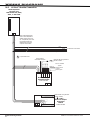
4.1
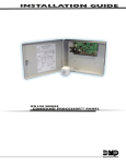
Mounting the Enclosure
The metal enclosure for the XR500 Series must be mounted in a secure, dry place to protect the panel from damage
due to tampering or the elements. It is not necessary to remove the XR500 Series PCB when installing the enclosure.
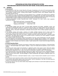
Figure 2 shows the mounting hole locations for the Model 350/350A Enclosures. Figure 3 shows the Model 341
Enclosure. Figure 4 shows the Model 352X panel cabinet and 352S shelf cabinet for multiple batteries.
The 350A Attack Resistant enclosure is factory shipped with one knockout on the top left of the enclosure. As
needed, additional knockouts or antenna exits may be added at the time of installation. See Figure 2 for the
positions on the enclosure that can be added. Each additional knockout must be filled with conduit.
Note: When using the XR500 Series panel for listed applications, use the Model 350, 349, 341, or 352S enclosure for
standby batteries. When using the 352X or 352S in listed applications, the enclosure must be surface mounted on the
wall.
*
Enclosure Mounting Holes
J3
Phone Line
J6
Interface
Card
Expansion
Connector
J4
Tamper
XR500 Series
Canadian Panel
Link LED
Activity LED
J1
Ethernet
3-Hole
Pattern for
Accessory
Modules
J21
J23
RS-232
J22
LX-Bus
X
Output 1
J10
Battery
Start
OVC
J2
K6
J8
PROG
Output 2
Out1 Out2
Power
R
LED
L
K7
AC AC +B –B BELL GND RED YEL GRN BLK SMK GND Z1 GND Z2
1
2
3
4
5
6
7
8
9
10
11
12 13
14
3
4
5
6
J11
J16
Reset
Outputs 3-6
Z3 GND Z4 Z5 GND Z6
15 16
17
18 19
20
Z7 GND Z8 Z9+ Z9– Z10+ Z10–
21 22
23
24 25
26
27
28
*
*
Dual 1 3/4" and 1 3/8" Conduit Knockouts
Front and
Rear Tamper
Switches for
350A Attack
Resistant
Enclosure
* 350A Optional Knockout
Battery Shelf holds up to three 7 Ah Batteries
*
*
Figure 2: XR500 Series in Model 350 or 350A Enclosure
PEMs for optional battery bracket
Lid Mounting Holes (4 places)
Lid Mounting Holes
(4 places)
XR500 Series Panel
J3
Phone Line
J4
Tamper
Link LED
Activity LED
J1
Ethernet
J21
Power J23
R
LED
RS-232
J22
LX-Bus
Output 1 OVC Output 2
J2
J10
Battery
Start
K6
J8
PROG
Out1 Out2
L
X
J11
K7
AC AC +B –B BELL GND RED YEL GRN BLK SMK GND Z1 GND Z2
1
2
3
4
5
6
7
8
9
10
11
12 13
14
J16
Reset
3
4
5
6
Outputs 3-6
Z3 GND Z4 Z5 GND Z6
15 16
17
18 19
20
Z7 GND Z8 Z9+ Z9– Z10+ Z10–
21 22
23
24 25
26
27
28
Enclosure Mounting Holes (4 places)
Dual 1/2" and 3/4" Conduit Knockouts
Figure 3: XR500 Series in Model 341 Enclosure
Digital Monitoring Products
6
XR500 Series Canadian Installation Guide
Installation
56 VA
Transformer
Mounting
Plate
J3
Phone
Line
J4
Tamper
J1
Ethernet
Link LED
Activity LED
Power
LED
R
L
X
J23
RS232
5
4
3
2
XR500 Series
1
G
9
8
7
6
Canadian Panel
J22
LX-Bus
RED
J10
Output 1 OVC
AC +B
1
2
3
4
5
6
7
8
9
10
11 12
13 14
K7
Out2
–B BELL GND RED YEL GRN BLK SMK GND Z1 GND Z2
J6 Expansion Slot
Output 2
Outputs 3-6
AC
J8
Out1
RED
K6
Z3 GND Z4
Z5 GND Z6
15 16
17
18 19
J16
Reset
20 21
Z7 GND Z8 Z9+ Z9– Z10+Z10–
22
23
24 25
26 27
28
Mounting for one (1)
Zone Expansion Module.
Battery Shelf
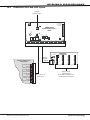
Figure 4: XR500 Series in Model 352X Enclosure and Separate 352S Enclosure with Shelves
4.2
Mounting Keypads and Zone Expansion Modules
DMP LCD keypads have removable covers that allow you to easily mount the keypad to a wall or other flat surface
using the screw holes on each corner of the base. Before mounting the base, connect the keypad wire harness leads
to the keypad cable from the panel and to any device wiring run to that location. Then attach the harness to the pin
connector on the PC board, mount the base, and install the keypad cover making sure all of the keys extend through
their respective holes.
For mounting keypads on solid walls, or for applications where conduit is required, use the Model 695 1-1/2” deep or
the Model 696 1/2” deep backboxes.
The DMP 711, 712-8, 714, 715, 716, and 717 modules are each contained in molded plastic housings with removable
covers. The base provides you with mounting holes for installing the unit to a wall, switch plate, or other surface.
XR500 Series Canadian Installation Guide
Digital Monitoring Products
7
Installation
4.3
Connecting LX-Bus and Keypad Bus Devices
Several factors determine the DMP LX-Bus™ and keypad bus performance characteristics: the wire length and gauge
used, the number of devices connected, and the voltage at each device. When planning an LX-Bus™ and keypad bus
installation, keep in mind the following information:
1. DMP recommends using 18 or 22-gauge unshielded wire for all keypad and LX-Bus circuits. Do not use
twisted pair or shielded wire for LX-Bus and keypad bus data circuits.
2.On keypad bus circuits, to maintain auxiliary power integrity when using 22-gauge wire do not exceed 500
feet. When using 18-gauge wire do not exceed 1,000 feet. To increase the wire length or to add devices,
install an additional power supply that is listed for Fire Protective Signaling, power limited, and regulated
(12 Vdc nominal) with battery backup.
Note: Each panel allows a specific number of supervised keypads. Add additional keypads in the unsupervised
mode. Refer to the panel installation guide for the specific number of supervised keypads allowed.
3.Maximum distance for any one bus circuit (length of wire) is 2,500 feet regardless of the wire gauge. This
distance can be in the form of one long wire run or multiple branches with all wiring totaling no more than
2,500 feet. As wire distance from the panel increases, DC voltage on the wire decreases. Maximum number
of LX-Bus devices on the first 2,500 foot circuit is 40 devices.
4. Maximum voltage drop between the panel (or auxiliary power supply) and any device is 2.0 Vdc. If the
voltage at any device is less than the required level, add an auxiliary power supply at the end of the circuit.
When voltage is too low, the devices cannot operate properly.
For additional information refer to the LX-Bus/Keypad Bus Wiring Application Note (LT-2031).
Expansion Interface Cards (Models 481, 462N, 462P, and 464-263H)
The LX-Bus provided on these cards requires only a 4-wire cable between the card and any devices connected to the
bus. You can connect devices (zone or output expansion modules) together on the same cable or provide separate
runs back to the card. Each LX-Bus provides up to 100 zones or outputs.
4.4
Wireless Keypad Association
Enable Wireless Keypad Association operation on both the keypad and panel.
To enable association operation in the keypad, access the Installer Options Menu (3577
RCV
J8
(INST)) and select RF Survey). The keypad logo LEDs turn on Red until association is
XMIT
successful.
Programming
To enable association operation in the XR500 panel, reset panel 3 times within 12
seconds. Allow the keypad bus Transmit/Receive LEDs to turn back on between each
reset.
For 60 seconds the panel listens for wireless keypads that are in the Installer Options
Figure 5: Keypad Bus LEDs
Menu (3577 CMD) and have not been programmed, or associated into another panel.
Those keypads are assigned to the first open device position automatically based upon
the order in which they are detected. The keypad logo turns Green to indicate it has been associated with the panel.
Primary Power Supply
5.1
AC Terminals 1 and 2
Connect the transformer wires to terminals 1 and 2 on the panel. Use no more than 70 ft. of 16 gauge or 40 ft. of 18
gauge wire between the transformer and the XR500 Series.
Always ground the panel before applying power to any devices: The XR500 Series must be properly
grounded before connecting any devices or applying power to the panel. Proper grounding protects
against Electrostatic Discharge (ESD) that can damage system components. See the Earth ground section.
5.2
Transformer Types
Use Model 327-CAN (16.5 Vac 50 VA) plug-in or Model FTA7516 from ATC Frost.
The transformer must be connected to an unswitched 120 Vac 60 Hz electrical outlet with at least .87A of
available current. Never share the transformer output with any other equipment.
5.3
J12 3-Pin Header for Transformer Types
Place the jumper on the left two pins for a Maximum 2 Amp (Bell=1 Amp; Aux=1 Amp) when using the Model 327-CAN
plug-in transformer (default).
Use an ATC Frost FTA7516 transformer and place the jumper on the right two pins for a Maximum, 3 Amps (Bell=1.5
Amp; Aux=1.5 Amp).
Secondary Power Supply
Digital Monitoring Products
8
XR500 Series Canadian Installation Guide
Installation
6.1
Battery Terminals 3 and 4
Connect the black battery lead to the negative battery terminal. The negative terminal connects to the enclosure
ground internally through the XR500 Series circuit
Battery
Start
XR550
board. Connect the red battery lead to the
Panel
battery positive terminal. Observe polarity when
AC AC +B –B BELL GND
connecting the battery.
Battery
You can add a second battery in parallel using the
DMP Model 318 Dual Battery Harness. DMP requires
each battery be separated by a PTC in the
battery harness wiring to protect each battery
from a reversal or short within the circuit. See
Figure 6.
318 Battery
Harness
To AC
Red
PTC
2
3
4
5
6
Panel Red and
Black Battery Cables
Red
PTC
318 Battery
Harness
1
Black
14 AWG to
Earth Ground
To Bell
Circuit
Black
Use sealed lead-acid batteries only:
Battery
Battery
Use the Model 365 (12 Vdc 9 Ah),
Model 366 (12 Vdc 18 Ah), Model 368 (12
Vdc 5.0 Ah), or Model 369 (12 Vdc 7 Ah)
Figure 6: Wiring Multiple Batteries
sealed lead‑acid rechargeable battery.
Batteries supplied by DMP have been tested to ensure proper charging with DMP products.
GEL CELL BATTERIES CANNOT BE USED WITH THE XR500 SERIES PANEL.
6.2
Earth Ground (GND)
To provide proper transient suppression, XR500 Series panel terminal 4 must be connected to earth ground using
14 gauge or larger wire. DMP recommends connecting to a cold water pipe, ground rod, or building ground only. Do
not connect to an electrical ground or conduit, sprinkler or gas pipes, or to a telephone company ground.
6.3
Battery Only Restart
When powering up the XR500 Series panel without AC power, briefly short across the battery start pads to pull in
the battery cutoff relay. The leads need a momentary short only. Once the relay has pulled in, the battery voltage
holds it in that condition. If the XR500 Series panel is powered up with an AC transformer, the battery cutoff relay is
pulled in automatically. For more information refer to Figure 1.
6.4
Battery Replacement Period
DMP recommends replacing the battery every 3 to 5 years under normal use.
6.5Discharge/Recharge
The XR500 Series battery charging circuit float charges at 13.9 Vdc at a maximum current of 1.0 Amps. Listed below
are the various battery voltage level conditions:
Battery Trouble:
Below 11.9 Vdc
Battery Cutoff:
Below 10.2 Vdc
Battery Restored:
Above 12.6 Vdc
6.6
Battery Supervision
The XR500 Series tests the battery when AC power is present. The test is done every three minutes and lasts for five
seconds. During the test, the panel places a load on the battery; if the battery voltage falls below 11.9 Vdc a low
battery is detected. If AC power is not present, a low battery is detected any time the battery voltage falls below
11.9 Vdc.
If a low battery is detected with AC power present, the test repeats every two minutes until the battery charges
above 12.6 Vdc indicating the battery has restored voltage. If a weak battery is replaced with a fully charged
battery, the restored battery will not be detected until the next two minute test is completed.
6.7
Battery Cutoff
The panel disconnects the battery any time the battery voltage drops below 10.2 Vdc. This prevents battery deep
discharge damage.
XR500 Series Canadian Installation Guide
Digital Monitoring Products
9
Installation
6.8
XR500 Series Canadian Power Requirements
During AC power failure, the XR500 Series panel and all connected auxiliary devices draw their power from the
battery. All devices must be taken into consideration when calculating the battery standby capacity. The following
table lists the XR500 Series panel power requirements. You must add the additional current draw of keypads, zone
expansion modules, smoke detector output, and any other auxiliary devices used in the system for the total current
required. The total is then multiplied by the number of standby hours required to calculate the total ampere-hours
required.
Standby Battery Power Calculations
Standby Current
XR500 Series Control Panel
Relay Outputs 1-2 (ON)
Switch Grounds 3-6 (ON)
Active Zones 1-8
Active Zones 9-10
2-Wire Smoke Detectors
Panel Bell Output
Qty
Qty
Qty
Qty
Qty
Qty
1 _ x 180mA 180 mA
_______
30mA ______
_______
5mA ______
_______
1.6mA ______
_______
4mA ______
_______
0.1mA ______
893A Dual Phone Line Module
Qty _______
x
461 Interface Adaptor Card
12mA ______
Alarm Current
Qty
Qty
Qty
Qty
Qty
Qty
1 _ x
_______
_______
_______
_______
_______
Qty _______
x
7mA ______
180mA
30mA
5mA
2mA*
30mA
0.1mA
1500mA
180 mA
______
______
______
______
______
______mA
50mA ______
7mA ______
462N Network Interface Card
Qty _______
x
50mA ______
Qty _______
x
50mA ______
462P Printer Interface Card
Qty _______
x
50mA ______
Qty _______
x
50mA ______
464-263H HSPA+ Cellular Communicator
Qty _______
x
15mA ______
Qty _______
x
48mA ______
481 Expansion Interface Card
Qty _______
x
15mA ______
Qty _______
x
28mA ______
1100X Wireless Receiver
Qty _______
x
46mA ______
Qty _______
x
46mA ______
1100XH Wireless High Power Receiver
Qty _______
x 160mA ______
Qty _______
x
160mA ______
860 Relay Output Module (one relay active)
All four relays active
Qty _______
x
34mA ______
138mA ______
Qty _______
x
34mA ______
138mA ______
865 Style Y or Z Notification Module
Qty _______
x
26mA ______
Qty _______
x
85mA ______
866 Style W Notification Module
Qty _______
x
45mA ______
Qty _______
x
76mA ______
867 LX-Bus Style W Notification Module
Qty _______
x
30mA ______
Qty _______
x
86mA ______
869 Dual Style D Initiating Module
Qty _______
x
25mA ______
Qty _______
x
75mA ______
7060/7160 Thinline/7060A Aqualite Keypad
Qty _______
x
72mA ______
Qty _______
x
80mA ______
7063/7163 Thinline/7063A Aqualite Keypad
Qty _______
x
85mA ______
Qty _______
x
100mA ______
7070/7170 Thinline/7070A Aqualite Keypad
Active Zones (EOL Installed)
Qty _______
x
72mA ______
1.6mA ______
Qty _______
Qty _______
x
x
87mA ______
2mA* ______
7073/7173 Thinline/7073A Aqualite Keypad
Active Zones (EOL Installed)
Qty _______
x
85mA ______
1.6mA ______
Qty _______
Qty _______
x
x
100mA ______
2mA* ______
7872 Graphic Touchscreen Keypad
Active Zones (EOL Installed)
Qty _______
Qty _______
x 145mA ______
x 1.6mA ______
Qty _______
Qty _______
x
x
215mA ______
2.0mA ______
7873 Graphic Touchscreen Keypad
Active Zones (EOL Installed)
Qty _______
Qty _______
x 143mA ______
x 1.6mA ______
Qty _______
Qty _______
x
x
243mA ______
2.0mA ______
734 Wiegand Interface Module
Active Zones (EOL Installed)
Annunciator (ON)
Qty _______
Qty _______
x
x
Qty _______
Qty _______
Qty _______
x
x
x
15mA ______
2mA* ______
20mA ______
734N Wiegand Interface Module
Active Zones (EOL Installed)
Annunciator (ON)
Wiegand Reader
Qty _______
Qty _______
x 146mA ______
x 1.6mA ______
Qty _______
x 200mA ______
Qty
Qty
Qty
Qty
_______
_______
_______
_______
x
x
x
x
148mA
2mA*
20mA
200mA
______
______
______
______
734N-WiFi Wiegand Interface Module
Active Zones (EOL Installed)
Annunciator (ON)
Wiegand Reader
Qty _______
Qty _______
x 146mA ______
x 1.6mA ______
Qty _______
x 200mA ______
Qty
Qty
Qty
Qty
_______
_______
_______
_______
x
x
x
x
148mA
2mA*
20mA
200mA
______
______
______
______
Copy Sub-Totals to next page
*Based on 10% of active zones in alarm.
Digital Monitoring Products
10
15mA ______
1.6mA ______
Sub-Total Standby ______mA
Sub-Total Alarm ______mA
XR500 Series Canadian Installation Guide
Installation
Standby Battery Power Calculations
Standby Current
Alarm Current
736P POPIT Interface Module
Radionics Popex, POPITs, OctoPOPITs
Qty _______
Qty _______
x 25mA ______
x ___mA ______
Qty _______
Qty _______
x
x
25mA ______
___mA ______
738A Ademco Wireless Interface Module
Qty _______
x
75mA ______
Qty _______
x
75mA ______
710 Bus Splitter/Repeater Module
Qty _______
x
32mA ______
Qty _______
x
32mA ______
711 Zone Expansion Module
Active Zone (EOL Installed)
Qty _______
Qty _______
x
x
11mA ______
1.6mA ______
Qty _______
Qty _______
x
x
11mA ______
2mA* ______
714 Zone Expansion Module
Active Zones (EOL Installed)
Qty _______
Qty _______
x
x
7mA ______
1.6mA ______
Qty _______
Qty _______
x
x
7mA ______
2mA* ______
712-8 Zone Expansion Module
Active Zones (EOL Installed)
Qty _______
Qty _______
x
x
17mA ______
1.6mA ______
Qty _______
Qty _______
x
x
17mA ______
2mA* ______
714-8, 714-16 Zone Expansion Module
Active Zones (EOL Installed)
Qty _______
Qty _______
x
x
20mA ______
1.6mA ______
Qty _______
Qty _______
x
x
20mA ______
2mA* ______
715 Zone Expansion Module
Active Zones (EOL Installed)
2-Wire Smokes
Qty _______
Qty _______
Qty _______
x
x
x
7mA ______
4mA ______
.1mA ______
Qty _______
Qty _______
Qty _______
x
x
x
7mA ______
30mA* ______
.1mA ______
715-8, 715-16 Zone Expansion Modules
Active Zones (EOL Installed)
2-Wire Smokes
Qty _______
Qty _______
Qty _______
x
x
x
20mA ______
4mA ______
.1mA ______
Qty _______
Qty _______
Qty _______
x
x
x
20mA ______
30mA* ______
.1mA ______
716 Output Expansion Module
Active Form C Relays
Qty _______
x
13mA ______
Qty _______
Qty _______
x
x
13mA ______
12mA ______
717 Graphic Annunciator Module
Annunciator Outputs
Qty _______
x
10mA ______
Qty _______
Qty _______
x
x
10mA ______
1mA ______
521LX, 521LXT Smoke Detectors
Qty _______
x
8.8mA ______
Qty _______
x
28mA* ______
2W-BLX, 2WT-BLX Smoke Detectors
Qty _______
x
15mA ______
Qty _______
x
36mA* ______
572 Indicator LED
Qty _______
x
20mA ______
Qty _______
x
20mA ______
Aux. Powered Devices on Terminals 7 and 11
Other than Keypads and LX-Bus Modules
______mA
______mA
This page only
Sub-Total Standby ______mA
Sub-Total Alarm ______mA
Sub-Totals from previous page
*Based on 10% of active zones in alarm
Sub-Total Standby ______mA
Total Standby ______mA
Sub-Total Alarm ______mA
Total Alarm ______mA
_______ mA-hours
Total Standby ______ mA x number of Standby Hours needed ______ =
Total Alarm ______ mA +_______ mA-hours
Total _______ mA-hours
X
.001
= _______ Amp-hrs
Required
Refer to section 6.9 for standby battery selection.
XR500 Series Canadian Installation Guide
Digital Monitoring Products
11
Installation
6.9
Standby Battery Selection
To choose the type and number of batteries needed for 24, 60, or 72 hours of standby power based on the Amp Hours
Required calculation from section 6.8 XR500 Series Power Requirements, perform the following:
1.Select the desired standby hours required from the table below: 24, 60, or 72 hours
2.Select the desired battery size: Model 368 (12 Vdc 5.0 Ah), Model 369 (12 Vdc 7 Ah),
Model 365 (12 Vdc 9 Ah), Model 366 (12 Vdc 18 Ah).
3.Select a Max. Ah Available number that is just greater than the number calculated in Amp Hours Required.
4.Install the number of batteries shown in the corresponding No. of Batteries required column.
Example: If the Amp Hours Required calculation equals 22 Ah for 24 hours of standby time and 4.5 Ah batteries
are desired, install six (6) Model 368 (12 Vdc, 5.0 Ah) batteries.
Note: You can use a Model 327-CAN Plug-in 50VA with up to 36Ah of standby battery or ATC Frost FTA7516 75VA
transformer with any of the number of batteries choices listed below.
24 hours of standby power
5.0 Ah Batteries
7 Ah Batteries
7.7 Ah Batteries
9 Ah Batteries
18 Ah Batteries
Max. Ah No. of
Max. Ah No. of
Max. Ah No. of
Max. Ah No. of
Max. Ah No. of
Available Batteries
Available Batteries
Available Batteries
Available Batteries
Available Batteries
8
2
6
1
6
1
8
1
16
1
12
3
12
2
13
2
16
2
32
2
16
4
18
3
20
3
24
3
48
3
20
5
24
4
27
4
32
4
24
6
31
5
34
5
40
5
28
7
37
6
41
6
32
8
43
7
36
9
Note: 48 hours is the typical battery recharge time for any of the Number of Batteries
shown in this section.
40
10
60 hours of standby power
7 Ah Batteries
7.7 Ah Batteries
Max. Ah No. of
Max. Ah No. of
Available Batteries
Available Batteries
13
2
14
2
20
3
22
3
27
4
29
4
33
5
37
5
40
6
44
6
47
7
52
7
54
8
59
8
60
9
67
9
67
10
9 Ah Batteries
Max. Ah No. of
Available Batteries
17
2
26
3
34
4
43
5
52
6
61
7
69
8
18 Ah Batteries
Max. Ah No. of
Available Batteries
17
1
34
2
52
3
69
4
Note: 48 hours is the typical battery
recharge time for any of the Number of
Batteries shown in this section.
72 hours of standby power
9 Ah Batteries
18 Ah Batteries
Max. Ah No. of
Max. Ah No. of
Available Batteries
Available Batteries
16
2
16
1
25
3
33
2
33
4
50
3
42
5
67
4
50
6
59
7
Note: 72 hours is the typical battery recharge time required for any of the Number of
Batteries shown in this section.
67
8
Note: If the Amp Hours Required calculation is greater than any Max. Ah Available number shown on a table, then
add power supply(s) to power some system devices allowing the Amp Hours Required calculation to be reduced. See
the 710 Bus Splitter/Repeater Installation Guide (LT-0310).
Digital Monitoring Products
12
XR500 Series Canadian Installation Guide
Installation
7.1
Terminals 5 and 6
Bell Output
Terminal 5 supplies positive 12 Vdc to power alarm bells or horns. This output can be steady, pulsed, or temporal
depending upon the Bell Action specified in Bell Options. Terminal 6 is the ground reference for the bell circuit. This
supervised output detects 1k Ohms or less as normal. The indicating appliance can supply this resistance. If using a
horn or siren, a 1k Ohm 1/2 W EOL resistor (provided) should be added across the bell circuit to provide supervision.
See the Notification Appliance section for a list of approved notification appliances and the Wiring Diagrams for
connections.
Keypad Bus
8.1Description
XR500 Series panel terminals 7, 8, 9, and 10 are for the keypad bus. You can connect up to sixteen supervised
keypads and multiple unsupervised keypads to the XR500 Series. In addition to DMP LCD keypads, you can also
connect any combination of zone expansion modules to the data bus. Refer to the specific device installation sheet
for the maximum number of Keypad Bus devices.
Refer to the section titled LX-Bus for complete information about the LX-Bus 4-pin header and expansion slot.
Note: Do not use shielded wire for LX-Bus/Keypad Bus circuits.
8.2
Terminal 7 - RED
This terminal supplies positive 12 Vdc Regulated to power DMP LCD keypads and zone expansion modules. Terminal 7
also supplies power for any auxiliary device. The ground reference for terminal 7 is terminal 10.
The output current is shared with the smoke power output on terminal 11 and Zones 9 and 10. Current draw for all
connected devices must not exceed the panel maximum current rating. See Power Supply in the Compliance section
for maximum current in a fire listed application.
8.3
Terminal 8 - YELLOW
Terminal 8 receives data from keypads and zone expansion modules. It cannot be used for any other purpose.
8.4
Terminal 9 - GREEN
Terminal 9 transmits data to keypads and zone expansion modules. It cannot be used for any other purpose.
8.5
Terminal 10 - BLACK
Terminal 10 is the ground reference for DMP LCD keypads, zone expansion modules, and all auxiliary devices being
powered by terminal 7.
8.6
J8 Programming Connection
A 4-pin header (J8) is provided to connect a keypad when using a DMP Model 330 Programming Cable. This provides a
quick and easy connection for panel programming.
You may also use the J8 Programming Header to connect Keypad Bus devices. This is an alternative to connecting
keypad bus devices to terminals 7, 8, 9, and 10.
8.7
OVC LED
The Overcurrent LED (OVC) lights Red when the devices connected to the Keypad Bus and LX-Bus(es) draw more
current than the panel rating. The OVC is located above Outputs 1 and 2 on the panel and turns a steady Red when
lit. When the OVC LED lights Red, the LX-Bus(es) and Keypad bus are shut down.
Smoke and Glassbreak Detector Output
9.1
Terminals 11 and 12
Terminal 11 supplies positive 12 Vdc Regulated to power 4-wire smoke detectors and other powered devices. This
output can be turned off by the user for 5 seconds using the Sensor Reset User Menu option to allow latched devices
to reset. Terminal 12 is the ground reference for terminal 11.
9.2
Current Rating
The Output current from terminal 11 is shared with terminals 7, 25, and 27.
The total current draw of all devices powered from the panel must be included with terminal 11
calculations and must not exceed the maximum output rating.
XR500 Series Canadian Installation Guide
Digital Monitoring Products
13
Installation
Protection Zones
10.1 Terminals 13–24
Zones 1 to 8 (terminals 13 to 24) on the XR500 Series panel are all grounded burglary zones. For programming
purposes, the zone numbers are 1 through 8. Listed below are terminal 13 to 24 connection functions.
Terminal
Function
Terminal
Function
13
Zone 1 voltage sensing
19
Zone 5 voltage sensing
14
Ground for Zones 1 and 2
20
Ground for Zones 5 and 6
15
Zone 2 voltage sensing
21
Zone 6 voltage sensing
16
Zone 3 voltage sensing
22
Zone 7 voltage sensing
17
Ground for Zones 3 and 4
23
Ground for Zones 7 and 8
18
Zone 4 voltage sensing
24
Zone 8 voltage sensing
The voltage sensing terminal measures the voltage across a 1k Ohm End-of-Line resistor to ground. Use DMP Model
311 1k Ohm resistors. Dry contact sensing devices can be used in series (normally-closed) or in parallel (normallyopen) with any of the burglary protection zones.
1K Ohm
Normally
Closed
1K Ohm
Normally Open
1K Ohm
Combination Normally Open
and Normally Closed
Figure 7: Protection Zone Wiring
10.2 Operational Parameters
Each protection zone detects three conditions: Open, Normal, and Short. Listed below are voltage and resistance
parameters for each condition:
Condition
Open
Normal
Short
Resistance on zone
over 1300 ohms
600 to 1300 ohms
under 600 ohms
Voltage on positive terminal
over 2.0 Vdc
1.2 to 2.0 Vdc
under 1.2 Vdc
10.3 Dual EOL
The XR500 Series Canadian panel supports the use of dual 1K EOL resistors on panel zones one to
eight. Two EOL resistors are used so a wire trouble can be indicated during the disarm period.
When dual end-of-line operation is chosen in panel programming, normal zone processing occurs
with the following exception: When processing an open zone and a trouble or alarm message is
NOT programmed to be sent for the open state, the panel checks to see if the wire is cut. If the
wire is cut, the panel automatically sends an alarm if armed or trouble is disarmed.
ZONE STATUS
Disarmed
Armed
Zone Wires Open
Trouble
Alarm
Zone Wires Short
Trouble
Alarm
Contact Normal
Normal
Normal
Contact Open
Normal
Alarm
Zone wires
to Panel
Zones 1-8
1K Ohm
1K Ohm
Indicating Device
10.4 Zone Response Time
A condition must be present on a zone for 500 milliseconds before it is detected by the XR500 Series panel. Ensure
detection devices used on the protection zones are rated for use with this delay. Zones 1-10 can also be programmed
for a fast response delay of 160 milliseconds.
10.5 Keyswitch Arming Zone
A keyswitch on an Arming type zone allows selected areas to arm and disarm without having to enter a user code.
Digital Monitoring Products
14
XR500 Series Canadian Installation Guide
Installation
Powered Zones for 2-Wire Smoke Detectors
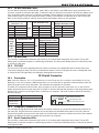
11.1 Terminals 25–26 and 27–28
Panel terminals 25 through 28 provide two resettable Class B, Style A, 2-wire powered zones. For programming
purposes the zone numbers are 9 and 10.
Note: The maximum wire length for either zone 9 or zone 10 is 3000 feet using 18 AWG or 1000 feet using 22
AWG. The maximum voltage is 14 Vdc and the maximum normal standby current is 1.25mA DC. The maximum line
impedance is 100 Ohms. The maximum short circuit current is 56mA.
When using all other zone expansion modules, use listed Model 309 EOL resistors. The compatibility identifier for the
zones is A.
Note: Do not mix detectors from different manufacturers on the same zone.
Caution: Performing a Sensor Reset momentarily drops power to the devices on Zones 9 and 10. The panel
views these zones (9 and 10) as “Open” while the power is absent.
XR500 Series Canadian Installation Guide
Digital Monitoring Products
15
Installation
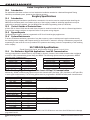
11.2 Compatible 2-Wire Smoke Detector Chart
Manufacturer
Model
Detector
ID
Base
Detection Systems
DS230, DS230F
B/A
MB2W, MB2WL
A
8.5-33
10
Detection Systems
DS250, DS250TH
B
MB2W, MB2WL
A
8.5-33
10/12
Detection Systems
DS250HD
B
MB2W, MB2WL
A
8.5-33
10
B/A
MB2W, MB2WL
A
8.5-33
17
8.5-33
10/12
715, 715-8,
715-16, 725
8-35
14
725
Detection Systems
DS260
DS282, DS282TH,
Detection Systems
DS282THC,
DS282THS
SLR-835B-2
Hochiki
SLR-835BH-2
Hochiki
SLR-24, SLR-24H
SIJ-24, DCD-190,
Hochiki
DCD-135
Hochiki
SLR-24, SLR-24H
Hochiki
SIJ-24
Hochiki
DCD-190, DCD-135
429AT, 521B,
Sentrol/ESL
521BXT, 521NB,
521NBXT
429C, 429CT,
Sentrol/ESL
521B/BXT
429CRT, 429CST,
Sentrol/ESL
429CSST, 521CRXT
711U, 712U,
Sentrol/ESL
713-5U, 713-6U,
721U, 721UT
Base
DC
# of
Zone
Panel
ID
Voltage Detectors Expansion Zones
Range (12V/24V) Modules
B
HD-6
N/A
HD-3
NS4-220
HB-3
15-33
15
725
HD-3
NS4-220
HB-3
15-33
15
725
HD-3
HD-3
HD-3
NS6-220
NS6-220
NS6-220
HB-3
HB-3
HB-3
15-33
15-33
15-33
15
20
16
725
725
725
S09A
6.5-20
12
715, 715-8,
715-16
S10A
8.5-33
12
725
S11A
8.5-33
12
725
S10A
701E, 70-1U,
702E, 702U
S00
8.5-33
12
725
701E, 701U,
702E, 702U,
702RE, 702RU
S00
8.5-33
12
725
8.5-35
10
Sentrol/ESL
731U, 723U
S11A
System Sensor
1400
A
System Sensor
1151, 2151
A
B110PL, B401
8.5-35
10/10
System Sensor
1451, 2451TH
A
B401, B401B
8.5-35
10
System Sensor
1451DH
A
DH400
8.5-35
10
A
8.5-35
10
A
8.5-35
10
8.5-35
10
System Sensor
System Sensor
2100T, 2100B,
2100TB, 2100D,
2100TD
2400, 2400AT,
2400AIT, 2400TH
725
715, 715-8,
715-16, 725
715, 715-8,
715-16
725
B401, B401B,
DH400
System Sensor
2451
A
System Sensor
2W-B, 2WT-B
A
8.5-35
10
System Sensor
2WTA-B, 2WTR-B
A
8.5-35
10
System Sensor
DH100P, DH100LP
A
8.5-35
10
715, 715-8,
715-16
715, 715-8,
715-16, 725
715, 715-8,
715-16
715, 715-8,
715-16
715, 715-8,
715-16
715, 715-8,
715-16
715, 715-8,
715-16
715, 715-8,
715-16
715, 715-8,
715-16
715, 715-8,
715-16, 725
9 & 10
9 & 10
9 & 10
9 & 10
9 & 10
9 & 10
9 & 10
9 & 10
9 & 10
9 & 10
9 & 10
9 & 10
9 & 10
9 & 10
Figure 7: Compatible 2-Wire Smoke Detectors
Digital Monitoring Products
16
XR500 Series Canadian Installation Guide
Installation
Dry Contact Relay Outputs
12.1Description
The XR500 Series panel provides two programmable auxiliary SPDT relays when equipped with two DMP Model 305
relays in sockets K6 (Output 1) and K7 (Output 2) and a Model 431 Output Harness on the J2 6-pin Header. Each relay
provides one SPDT set of contacts that can be operated by any of the functions listed below:
1)Activation by zone condition: Steady, Pulsing, Momentary, and Follow
2)Activation by 24-hour 7-day schedule: One on and one off time a day for each relay
3)Manual activation from the DMP LCD keypad menu
4)Communication failure
8) Exit and Entry timers
5)Armed area annunciation
9) System Ready
6)Fire Alarm, Fire Trouble or Supervisory
10) Late to Close
7)Ambush Alarm
Refer to the XR500 Series Canadian Programming Guide (LT-0679CAN) for specific information.
12.2 Contact Rating
The Model 305 relay contacts are rated for 1 Amp at 30 Vdc (allows .35 power factor). You can connect auxiliary
power to the Relay Output 1 common terminal by installing the gray harness wire to terminal 7. Current draw for all
connected devices must not exceed the panel maximum current rating.
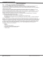
12.3 Model 431 Output Harness Wiring
The relay contacts are accessible by installing the DMP 431 Output Harness on the 6-pin header labeled J2. Output
2 uses the top three prongs, and Output 1 uses the bottom three prongs. The wire harness and contact locations are
shown below:
Contact
Color
Output 1 normally closed
Violet
Output 1 common
Gray
Output 1 normally open
Orange
Output 2 normally closed
Violet with white stripe
Output 2 common
White with gray stripe
Output 2 normally open
Orange with white stripe
The relay contacts must be connected to devices located within the same room as the XR500 Series panel.
Annunciator Outputs
13.1Description
The four programmable annunciator outputs can be programmed to indicate the activity of the panel zones or
conditions occurring on the system. Annunciator outputs do not provide a voltage but instead switch-to-ground a
voltage from another source. The outputs can respond to any of the conditions listed in the Description section for
Dry Contact Relays. Maximum voltage is 30 Vdc @ 50mA.
13.2 Model 300 Harness Wiring
Access the open collector outputs by installing DMP 300 Harness on the 4-pin header labeled J11. The output
locations are shown below. For listed applications, devices connected to the outputs must be located within the
same room as the panel.
Output
3
4
Color
Red
Yellow
Wire
1
2
Output
5
6
Color
Green
Black
Wire
3
4
13.3 Model 860 Relay Module
Connect a Model 860 Relay Module to the J11 on the XR500 Series Canadian panel to provide relays for outputs
3-6. Use these relays for electrical isolation between the alarm panel and other systems or for switching voltage to
control various functions. Power is supplied to the relay coils from a single wire connected to the panel auxiliary
power terminal 7. The module includes one relay and provides three additional sockets for expansion of up to four
relays. Mount the 860 inside the panel enclosure using the 3-hole pattern and plastic standoffs. Refer to the 860
Module Install Sheet (LT-0484) as needed.
Relay Contact Rating: 1 Amp at 30 Vdc (allows .35 power factor)
XR500 Series Canadian Installation Guide
Digital Monitoring Products
17
Installation
J23 6-Pin Header
14.1Description
The XR500 Series Canadian Command Processor™ panel supports RS-232, LX-Bus, and DMP Wireless operation. Only
one operation can function at a time. Install a jumper on one pair of J23 headers to indicate how the panel is
programmed to operate. Refer to the table below when installing a jumper on J23. When a jumper is installed or
moved on the 6-pin header, briefly reset the panel using the J16 jumper to activate the selected operation.
Note: Only one operation, RS-232, LX-Bus, or DMP Wireless can function at a time.
Letter
R
L
X
J23 6-Pin Header
Operation
Standard RS-232
LX-Bus
1100 Series DMP Wireless
J21
J23
RS-232
R
L
X
J22
LX
LEDs
Xmit
Rec
Overcurrent
(OVC) LED
Figure 8: J23 6-Pin Header
J22 LX-Bus Expansion Connector
15.1Description
The XR500 Series Canadian Command Processor™ Panel supports up to 500 wireless bus zones or up to five LX-Bus
circuits. Each Interface card LX-Bus circuit provides 100 expansion zones. The maximum number of LX-Bus zones
available on a fully populated panel is 500. Use LX-Bus J22 Header for 100 zones. Install a single Interface Card
Connector on the board to support 100 additional zones for a total of 200 zones. To install up to five Interface Cards
install a Model 461 Interface Adaptor Card.
15.2 J22 LX-Bus Header
Note: Only one connector, J21 or J22 can function at a time. Either use J21 to connect a serial device for PC Log
Reporting, or use J22 to connect an LX-Bus or DMP Wireless device. Operation is determined by where you install
the jumper on the J23 6-Pin header. See the Connecting LX-Bus and Keypad Bus Devices section for maximum wiring
distances.
For each connection, respect wire colors when connecting devices and use all four wires. After placing the jumper
on the J23 6-Pin header to enable the required operation, briefly reset the panel using the J16 jumper to activate
operation.
Wireless Bus Operation: Place a jumper on the two pins next to the letter “X” on the J23 6-Pin header. When
using J22 as a wireless bus, connect a DMP Model 300 4-wire Harness to the J22 4-pin header labeled LX. Connect
the other end to the J3 header on the 1100X or 1100XH Wireless Receiver. This provides up to 500 wireless zones
numbered 500 to 999. Refer to the 1100X Wireless Receiver Install Guide (LT-0708) or the 1100XH Wireless Receiver
Install Guide (LT-0970).
LX-Bus Operation: Place a jumper on the two pins next to the letter “L” on the J23 6-Pin header. When using J22 as
an LX-Bus, connect a DMP Model 300 4-wire Harness to the J22 4-pin header labeled LX. This provides the first 100
LX-Bus zones numbered 500-599. No LX-Bus Interface Card is required.
Note: Do NOT use shielded wire when using the J22 LX-Bus Header.
RS-232 Operation: Place a jumper on the two pins next to the letter “R” on the J23 6-Pin header and refer to J21
Serial Connector.
Digital Monitoring Products
18
XR500 Series Canadian Installation Guide
Installation
15.3 LX-Bus Interface Cards
You can add one Interface Card (Model 481, 462N, 462P, or 464-263H) to the XR500 Series using J6 Interface Card
Connector located on the board right edge. To add more than one Interface Card install a 461 Interface Adaptor Card
using J6 Interface Card Connector on the board right edge. The 461 Adaptor Card allows up to five Interface Cards
to be installed. Refer to the 461 Installation Sheet (LT-0736). Each Interface card provides up to 100 LX-Bus Zones.
Refer to the following tables to identify zone locations and numbers relative to J22 operation.
J22 LX-Bus Enabled
(Set J23 to “L”)
LX-Bus Zone Numbers
1
500-599
AND
J22
LX-Bus
NOT
Enabled
(J23
NOT set
to “L”)
461 Adaptor Card and
Multiple Interface Cards
LX-Bus Zone Numbers
LX-Bus Zone Numbers
2
600-699
2 (A)
600-699
OR
3 (B)
700-799
4 (C)
800-899
5 (D)
900-999
One Interface Card
461 Adaptor Card and
Multiple Interface Cards
LX-Bus Zone Numbers
LX-Bus Zone Numbers
1
500-599
1 (A)
500-599
OR
2 (B)
600-699
3 (C)
700-799
4 (D)
800-899
5 (E)
900-999
One Interface Card
15.4 LX-Bus LEDs
The two LEDs, located near the bottom-right corner of J21 indicate data transmission and receipt. The top LED
flashes green to indicate the panel is transmitting LX-Bus data. The bottom LED flashes yellow to indicate the panel
is receiving LX-Bus data.
15.5 OVC LED
The Overcurrent LED (OVC) lights Red when the devices connected to the Keypad Bus and LX-Bus(es) draw more
current than the panel rating. The OVC is located above Outputs 1 and 2 on the panel and turns a steady Red when
lit. When the OVC LED lights Red, the LX-Bus(es) and Keypad bus shut down.
J21 Serial Connector
16.1Description
Note: Only one connector, J21 or J22 can function at a time. Either use J21 to connect a serial device for PC Log
Reporting, or use J22 to connect a DMP Wireless device or an LX-Bus device. Operation is determined by where you
install the jumper on the J23 6-Pin header. The maximum line impedance is 100 Ohms.
To enable J21 to operate in RS-232 mode, place a jumper on the two pins next to the letter “R” on the J23 6-Pin
header and briefly reset the panel using the J16 jumper to activate the selected operation. Panel programming using
Remote Link™ can be set up through a direct connection to a computer. The Serial Connector allows the following
operation options.
XR500 Panel
PC Log Reports
XR500N/XR500E Panel
PC Log Reports
Remote Link™
Programming
16.2 Computer Connection to J21
J21
R
L
X
J23
DB-9 Female Connector
RS-232
J22
Serial Data Xmit LED
Serial Data Rec(eive) LED
Figure 9: J21 Serial Connection
Use a straight through RS-232 Serial cable with a DB-9 female connector on one end and a DB-9 male connector on
the other end. Plug the DB-9 male connector end of the cable onto the XR500 Series panel J21 RS-232 connector.
Plug the DB-9 female connector end of the cable onto the DB‑9 male connector located at the back of the computer.
Program the XR500 Series panel as needed then disconnect the computer.
16.3 Serial Connector LEDs
The two LEDs, located near the bottom-right corner of J21 indicate data transmission and receipt. The top LED
flashes green to indicate the panel is transmitting serial data. The bottom LED flashes yellow to indicate the panel is
receiving serial data.
XR500 Series Canadian Installation Guide
Digital Monitoring Products
19
Installation
J1 Ethernet Connector (XR500N/XR500E only)
17.1Description
The J1 Ethernet Connector is available on the XR500N/XR500E Network version to connect directly to an Ethernet
network using a standard patch cable. The maximum impedance is 100 Ohms.
17.2 Ethernet LEDs
The two LEDs, located to the left of J1 Ethernet Connector, indicate network
connection. The top, Link LED lights up green to indicate a valid receive
connection from the host network. The bottom, Activity LED flashes yellow to
indicate messages are being sent and received.
Link LED
Activity LED
J1
Ethernet
Figure 10: J1 Header and LEDs
J3 Telephone RJ Connector
18.1Description
Connect the panel to the public telephone network by installing a DMP 356 RJ Cable between the panel J3 connector
and the RJ31X or RJ38X phone block. The maximum impedance is 100 Ohms. CAUTION - To reduce the risk of fire,
use only No. 26 AWG or larger telecommunication line cord, such as DMP Model 356 Series Phone Cords.
18.2 J10 893A Connector
Connect an 893A Dual Phone Line Module to J10 on the XR500 Series. Refer to the 893A Installation Sheet (LT‑0135)
for complete information.
18.3 Notification
The user must not repair registered terminal equipment. In case of trouble, immediately unplug the device from the
telephone jack. The factory warranty provides for repairs. Registered terminal equipment may not be used on party
lines or in connection with coin telephones. Notify the telephone company with the following information:
a. The particular line(s) where the service is connected
b. This Class A digital apparatus complies with Canadian ICES-003.
c. The ringer equivalence
d. The device make, model, and serial number
18.4 Phone Line Monitor
The XR500 Series panel has a built-in telephone monitor that monitors the phone line voltage to verify the
connection to the central office. Figure 11 and the table below identify the phone block pin layout, wire numbers,
and colors.
Wire Number
1
2
3
4
5
6
7
8
Wire Color
Gray
Orange
Black
Red
Green
Yellow
Blue
Brown
To Telephone
Line
Ring
Tip
5
4
6
3
7
2
1
8
Ring 1
To Premise
Phone
RJ31X or RJ38X
Phone Block
Tip 1
Figure 11: Phone Jack Wiring
The wires on the RJ31 that feed pins 4 and 5 should be the ONLY wires on the D-marc. All other house phone wiring
should be tied to pins 1 and 8 coming back from the RJ31.
Dial tone must come into RJ31X on pins 4 and 5 and go back to house phones from pins 1 and 8. Follow these steps
to determine if panel is seizing the line:
1.Unplug phone cord from RJ31X
2.Place butt-set on pins 4 and 5
3.Listen for dial tone. With dial tone present, lift either wire from pins 1 or 8
4.Listen for dial tone again. If the dial tone is present, RJ31X wiring is correct. If no dial tone is present, the
RJ31X wiring is backwards. Rewire so dial tone is coming IN on 4 and 5.
If you still have trouble with the phone line, you may need to replace the RJ cord. If the dial tone is still not
present, swap out the RJ31X phone block.
Digital Monitoring Products
20
XR500 Series Canadian Installation Guide
Installation
Reset and Tamper Headers
19.1 J16 Reset Header
The reset header is located just above the terminal strip on the right side of the circuit board and is used to reset
the XR500 Series microprocessor. To reset the panel when first installing the system, install the reset jumper before
applying power to the panel. After connecting the AC and battery, remove the reset jumper.
To reset the panel while the system is operational, for example, prior to reprogramming, install the reset jumper
without powering down the system. Remove the reset jumper after one or two seconds.
After resetting the panel, begin programming within 30 minutes. If you wait longer than 30 minutes, you must reset
the panel again.
J3
Phone Line
J4
Tamper
Link LED
Activity LED
Momentarily place the Reset
jumper over both of the J16
pins to reset the panel.
J1
Ethernet
75VA
50VA
J21
Power J23
R
LED
L
RS-232
J22
LX-Bus
X
Output 1
J10
Battery
Start
OVC
J2
K6
J8
PROG
Output 2
Out1 Out2
J12
AC AC +B –B BELL GND RED YEL GRN BLK SMK GND Z1 GND Z2
1
2
3
4
5
6
7
8
9
J6
Interface
Card
Expansion
Connector
10
11
12 13
14
K7
3
4
5
6
J11
J16
Reset
Outputs 3-6
Z3 GND Z4 Z5 GND Z6
15 16
17 18
19
20
Z7 GND Z8 Z9+ Z9– Z10+ Z10–
21 22
23
24
25
26
27
28
Figure 12: XR500 Series Canadian Panel Showing the Reset Jumper
19.2 J4 Tamper Header
The J4 header is for use with the optional DMP 306 Tamper Harness. The harness connects to one or more tamper
switches mounted inside the panel enclosure to supervise against unauthorized enclosure opening or removal. Refer
to the wiring diagram on the enclosure door for correct tamper switch wiring.
How the Tamper Works
If the enclosure is opened or removed while one or more of the system areas are armed, a panel tamper alarm is
indicated. If all areas are disarmed, a panel tamper trouble is indicated.
XR500 Series Canadian Installation Guide
Digital Monitoring Products
21
Compliance
20.1Introduction
Listed Compliance Specifications
For applications that must conform to a local authorities installation standard or a National Recognized Testing
Laboratory certificated system, please see the following sections.
21.1Introduction
Burglary Specifications
The programming and installation specifications contained in this section must be completed when installing the
XR500 Series Canadian panel in accordance with any of the burglary standards. Additional specifications may be
required by a particular standard. See the XR500 Series Canadian Programming Guide (LT-0679CAN).
21.2 Control Outside of Protected Area
A Potter EVD or Sentrol 5402 must be used when the panel is installed outside of the vault in a financial application.
Front and rear tamper switches are required. Refer to the system wiring diagram.
21.3 Bypass Reports
The Bypass Reports option must be programmed as YES for all listed burglary applications.
21.4 System Maintenance
To ensure continuous satisfactory operation of any alarm system, proper installation and regular maintenance by
the installing alarm company and frequent testing by the end user is essential. Offering a maintenance program and
acquainting the user with the correct procedures for system use and testing is also the responsibility of the installing
alarm company.
ULC S304-06 Specifications
Signal Receiving Center and Premise Burglar Alarm Control Units
22.1 For Medium or High Risk Applications: Level A3 Communication
Level A3 communication channel security is provided for Internet, Intranet, LAN or WAN networks when configured
as a NET or CELL communicating system using the XR500E. The following options must be programmed in XR500E
Canadian panel Communication:
NET PRIMARY
CELL PRIMARY:
SUB CODE:
YES
SUB CODE:
YES
CHECKIN TIME:
2 MINUTES
CHECKIN TIME:
3 MINUTES
FAIL TIME:
3 MINUTES
FAIL TIME:
3 MINUTES
SEND COMM TRBL:
YES
SEND COMM TRBL:
YES
TCP COMM:
YES
ENCRYPTION:
ENABLED
ENCRYPTION:
ENABLED
22.2 For Very High Risk Applications: Level A3 Plus P1 Communication
Additionally, XR500E communicating system may use two channels (NET plus Dialer, CELL plus Dialer, or NET plus CELL)
to send signals simultaneously. The following options must be programmed in XR500E Canadian panel Communication:
NET PRIMARY
DIALER PRIMARY:
SUB CODE:
YES
USE DAILY TEST
CHECKIN TIME:
2 MINUTES
FAIL TIME:
3 MINUTES
SEND COMM TRBL:
YES
TCP COMM:
YES
ENCRYPTION:
ENABLED
CELL PRIMARY
DIALER PRIMARY:
SUB CODE:
YES
USE DAILY TEST
CHECKIN TIME:
3 MINUTES
FAIL TIME:
3 MINUTES
SEND COMM TRBL:
YES
ENCRYPTION:
ENABLED
NET PRIMARY
CELL PRIMARY:
SUB CODE:
YES
YES
CHECKIN TIME:
2 MINUTES or less
24 HOURS or less
FAIL TIME:
3 MINUTES or less
SEND COMM TRBL:
YES
TCP COMM:
YES
ENCRYPTION:
ENABLED
In addition, the SCS-104 Network Line Card installed in the SCS-1R Receiver must have the ACK Substitution Message
programmed as NO.
Digital Monitoring Products
22
XR500 Series Canadian Installation Guide
Compliance
22.3 For Low Risk Applications: Level A1
Level A1 communication channel security is provided for Internet, Intranet, LAN or WAN networks when configured as
a NET communicating system using the XR500N.
22.4 For Low Risk Applications: Level P1
Level P1 communication channel security is provided when configured as a DD communicating system and a daily test
message using the XR500.
22.5 Dual Protection
For Medium or High Risk ULC Listed Applications: Use only zones 1-8 on the control panel and program Dual EOL as
Yes in panel programming. Program the Disarmed Short Message in Alarm Action of Zone Information programming as
a Trouble message.
If using a 714, 714-8, or 714-16 for dual protection, program two zones as the same name or equivalent and connect
to the contact in the protected area as show in the Dual Zone Protection diagram in the back of this guide.
22.6 Remote Arming
For ULC Listed applications, remote arming is not permitted.
22.7 Zone Expansion
Use of the following zone expanders are permitted for connection of burglary devices:
710 Bus Splitter Module
714 Zone Expander, 4 zones
715 Zone Expander, 4 zones
7070(A)/7073(A) Keypads, 4 zones
711 Zone Expander, Single 714-8 Zone Expander, 8 zones
715-8 Zone Expander, 8 zones
7170/7173 Keypads, 4 zones
712-8 Zone Expander, 8
714-16 Zone Expander, 16 zones 715-16 Zone Expander, 16 zones
ULC S559-04 Specifications
Equipment for Fire Signal Receiving Centers and Systems
23.1 For Fire Communicator Applications
For fire communicator applications, communication to the fire signal receiving center is provided for Internet,
Intranet, LAN or WAN networks when configured as a NET or CELL communicating system using the XR500 Series
panel. See wiring diagram in section 26.5 for additional information. Program one of the following options in panel
Communication:
Path 1 Type NET or CELL Primary with no Backup
Path 1 Programming
Comm Type = NET or CELL Checkin Min = 3
Path Type = Primary
Failtime Min = 3
Sub Code = No
Send Comm Trbl = Yes
Comm Path Trbl = Yes (Status List Programming)
Path 1 Type NET Primary and Path 2 Type CELL Backup
Path 1 Programming
Path 2 Programming
Comm Type = NET
Comm Type = CELL
Path Type = Primary
Path Type = Backup
Test Rpt = Yes
Test Rpt = Yes
Test Freq = 1 Dy
Test Freq = 1 Dy
Send Comm Trbl = Yes
Send Comm Trbl = Yes
Comm Path Trbl = Yes (Status List Programming)
23.2 Central Station Host Automation
The fire signal receiving center’s host automation system must recognize the following signals: Zone 1 Alarm = Fire
Alarm, Zone 2 Trouble = Fire Zone Trouble, Zone 3 Trouble = AC Trouble, Zone 4 Trouble = Battery Trouble, and Zone
5 Trouble = Ground Fault Trouble.
XR500 Series Canadian Installation Guide
Digital Monitoring Products
23
Compliance
Recommendations
24.1 ULC Burglary Installation Recommendations
1. In order to give the digital alarm communicator transmitter the ability to disconnect an incoming call to the
protected premises, telephone service should be of the type that provides for timed release disconnect.
2. Network access and domain access policies shall be set to restrict unauthorized network access and “spoofing” or
“denial of service” attacks.
3. Select Internet Service Providers that have redundant servers/systems, Back-up power, Routers with Firewall
enabled and Methods to identify and protect against “Denial of Service” attacks (i.e. via “spoofing”).
4. Power for network equipment as hubs, switches, routers, servers, modems, etc., shall be backed up or powered
by an un-interruptable power supply (UPS), stand-by battery or the control unit, capable of facilitating 24 hour
standby, compliant with Clauses 16.1.2 and 16.4.1 of CAN/ULC-S304-06.
5. Where such cannot be facilitated, the control unit shall support back-up communications for a secondary
communications path, subject to the following:
Low Risk and Medium Risk shall use a dialer as a minimum;
High Risk shall use cellular control channel or long range radio as a minimum; and
Very High Risk shall be equipped with 24 hour standby power. Note: Refer to Table 11 of CAN/ULC-S304-06 for
the risk levels.
6. Refer to CAN/ULC-S302, Installation and Classification of Burglar Alarm Systems for Financial and Commercial
Premises, Safes and Vaults, for requirements for a secondary communications path, where 24 hour standby cannot be
facilitated for all communications interface components as routers, hubs, switches and other network components.
7. Products or components of products used in communication channels, which perform communications functions
only, shall comply with the requirements applicable to communications equipment as specified in CAN/CSA-C22.2
No. 60950-1, Information Technology Equipment-Safety - Part 1: General Requirements. Such products or
components include, but are not limited to:
AHubs;
BRouters;
C Network interface devices;
D Third party communications service providers;
E Digital subscriber line (DSL) modems; and
F Cable modems
Digital Monitoring Products
24
XR500 Series Canadian Installation Guide
Compliance
False Alarm Reduction Programmable Options *
25.1 Shipping Defaults and Recommended Programming for ANSI/SIA CP-01-2010
SIA CP-01 FEATURE
PARAGRAPH # AND
DESCRIPTION
DMP XR500
PROGRAMMING
GUIDE LT‑0679
SECTION #
REQUIREMENT
RANGE
4.2.2.1 Exit Time
15.2 Exit Delay
Required
45 sec. - 250 sec.
(Programmable)
4.2.2.2 Progress
Annunciation
15.2 Exit Delay
Allowed
4.2.2.3 Exit Time
Restart
15.2 Exit Delay
Required Option
SHIPPING
DEFAULT
RECOMMENDED
PROGRAMMING*
60
Seconds
60 Seconds
Individual keypads
may be disabled per
zone
All
keypads
enabled
All keypads enabled
For re-entry during
exit time
Enabled
Enabled
4.2.2.5 Auto Stay Arm
on Unvacated Premises
Required Option
Area 1 = Perimeter
(except for
Area 2 = Interior
Install Guide (LT-0681) remote arming)
Enabled
Enabled for
Residential
Applications
4.2.4.4 Exit Time and
Progress Annunciation/
Disable - for Remote
Arm
Not Available on
Remote Arming
Allowed Option
4.2.3.1 Entry Delay(s)
8.3 Entry Delay
Required
30 sec. – 240 Sec. **
(Programmable)
33.3 Occupied
Premise - See XR500
Progress Annunciation
Not
Always disabled for
Available
Remote Arming
Remote Arming not
allowed for CP-01
installations.
30
Seconds
At least 30 Seconds **
4.2.5.1 Abort Window –
3.7 Transmit Delay
for Non‑Fire Zones
Required Option
Disable by zone or
zone type
Enabled
NT DY
EX Zone
Enabled
4.2.5.1 Abort Window
Time – for Non-Fire
Zones
3.7 Transmit Delay
Required
(Programmable
15 sec. - 45 sec. **
30
Seconds
At least 15 Seconds **
4.2.5.1.2 Abort
Annunciation
3.7 Transmit Delay
Annunciate that
Required Option no alarm was
transmitted (S45)
Yes
Yes
4.2.5.4.1 Cancel
Annunciation
Annunciate that
Always Enabled - Not
Required Option a Cancel was
Programmable
transmitted (S49)
Always
Enabled
Yes
4.2.6.1 & 4.2.6.2
Duress Feature
User Code + 1 =
Ambush Code Not
Available
4.3.1 Cross Zoning
Allowed Option
No 1 + derivative of
Code +1
another user code/no
Always
duplicates with other
Disabled
user codes
Not Programmable
16.22 Cross Zone
Required Option
Yes/No Zone
Programming
No
Enabled using two or
more programmed
zones
4.3.1 Programmable
Cross Zoning Time
8.4 Cross Zone Time
Allowed
4 sec. - 250 sec.
4 Seconds
Per walk path in
protected premises
4.3.2 Swinger Shutdown
8.7 Swinger Bypass
Trips
For all non-fire
Required
zones, shut down at
(Programmable)
1 or 2 trips
One (1)
trip
One (1) trip
Yes
Enabled (all zones)
No
Yes as required
(unless sensors can
self verify)
Disabled
Enabled if user has
call waiting
4.3.2 Swinger Shutdown
16.16 Swinger Bypass Allowed
Disable
For non-police
response zones
4.3.3 Fire Alarm
Verification
16.4 Zone Type
Required Option FV Type Zone
4.5 Call Waiting Cancel
3.19 Telephone
Number
Required Option
Include *70P in
Telephone Number
* Programming at installation may be subordinate to other listed requirements for the intended application.
** For listed Installations, combined Entry Delay and Transmit Delay should not exceed 1 minute.
XR500 Series Canadian Installation Guide
Digital Monitoring Products
25
Compliance
False Alarm Reduction Programmable Options (continued)
25.2 Call Waiting (ANSI/SIA CP-01-2010)
The Call Waiting default setting is disabled. To cancel the Call Waiting feature, program * (star) 7 0 P (pause), the
standard telephone code prefix that cancels call waiting, into the telephone number string. Cancel Call Waiting
for telephone lines that have Call Waiting operational on the telephone line. See the XR500 Series Canadian
Programming Guide (LT‑0679CAN).
Caution: A call waiting cancel programmed on a non-call waiting telephone line, would prevent
communication to the central station.
25.3 Occupied Premise (ANSI/SIA CP-01-2010)
When only two areas are used, and area one is named Perimeter, and area two is named Interior, and no exit type
zone transition occurs during the exit delay because the premise continues to be occupied, the Interior area will
automatically disarm at the end of the exit delay.
25.4 Entry Delay (ANSI/SIA CP-01-2010)
Only use Entry Delay 1. Do not use Entry Delay 2, 3, or 4. See the XR500 Series Canadian Programming Guide
(LT-0679CAN).
25.5 Minimum Installation Requirements (ANSI/SIA CP-01-2010)
SIA CP-01-2010 minimum system installation requirements include an XR500, a listed local Bell, and off premise
DACT communication to an SCS-1R receiver plus one of the following compatible keypads.
7060, 7063, 7070, or 7073 Thinline™ keypads
7060A, 7063A, 7070A, or 7073A Aqualite™ keypads
7160, 7163, 7170, or 7173 Thinline™ keypads
Digital Monitoring Products
26
XR500 Series Canadian Installation Guide
XR500 Series Canadian Installation Guide
Green LED
Red LED
Silence
BLO
BLI
Test
Common
+ 12 VDC
Rothenbuhler 5110
High Security Bell
K3
R
L
X
J23
J10
J22
RS-232
J21
J1
J4
Tamper
K6
J2
1
3
4
Output 1 N/C
Output 2 N/C
2
5
6
S
7
9
S
10
12 13
14
15 16
Output 1 Common
11
10K EOL
DMP Model 308
Output 2 Common
8
J11
18 19
10K EOL
DMP Model
308
17
20
J16
Reset
24
25
26
27
28
S = Supervised Circuit
23
Model 431 Output
Harness
21 22
Z3 GND Z4 Z5 GND Z6
K7
J6
Interface
Card
Expansion
Connector
Z7 GND Z8 Z9+ Z9– Z10+Z10–
XR500 Series Canadian
Command Processor™
Panel
J2 Output Header
All outputs must be located
within the same room as
the control panel.
AC AC +B –B BELL GND RED YEL GRN BLK SMK GND Z1 GND Z2
Battery
Start
J3
Wiring Diagrams
Wiring Diagrams
26.1 Rothenbuhler 5110 High Security Bell Wiring
Digital Monitoring Products
27
Wiring Diagrams
26.2 LX-Bus™ Module Connection
LX-Bus Expansion
Interface Card
DMP Models 481, 462N,
462P, or 464-263H.
Each LX-Bus Module must
have its own independent
address ranging from 00 to
99. A Supervisory zone must
be programmed into the
XR500 Series to properly
supervise each module.
S
S
S
S
Red
Yellow
To additional LX-Bus Modules
Green
Black
S
S
S
S
= Supervised Circuit
S
Optional LED wiring 50mA at
50 VDC resistive
Relay 3
S
S
Relay 2
Open Collector
Annunciator Outputs
Relay 1
S
LX-Bus™ Wiring
S
Relay 4
Form C Contacts
Typical
Normally Closed
Common
Normally Open
Model 716 Output
Expander Module
13m at 12 VDC
Optional LED wiring 50mA at
50 VDC resistive
Model 717 Graphic
Annunciator
Module
10m at 12 VDC
Digital Monitoring Products
28
XR500 Series Canadian Installation Guide
Wiring Diagrams
26.3 Model 860 Relay Module Connection
XR500 Series Canadian
Command Processor™
Panel
J4
Tamper
J3
J2 Output Header
All outputs must be located
within the same room as
the control panel.
J1
J21
R
L
X
J23
RS-232
J10
J2
K6
K7
AC AC +B –B BELL GND RED YEL GRN BLK SMK GND Z1 GND Z2
2
3
4
5
RED
YEL
GRN
BL K
J22
Battery
Start
1
J6
Interface
Card
Expansion
Connector
6
7
8
9
10
11
12 13
14
J11
15 16
17
4-wire J2
Harness
Assembly
J16
Reset
Z3 GND Z4 Z5 GND Z6
18 19
20
Model 860
Relay Module
1
2
3
4
Z7 GND Z8 Z9+ Z9– Z10+Z10–
21 22
23
24
25
26
27
28
{
Relay 2 {
Relay 3 {
Relay 4 {
Relay 1
N/C
Common
N/O
+12 VDC
Relay contact rating:
1 Amp @ 30 VDC, resistive
26.4 Dual Zone Protection
4-Conductor
Jacketed Cable
Protected Area such
as a Vault Door
Contact
Magnet
Tamper
Zone 2
1k EOL
XR500 Series Canadian Installation Guide
Zone 1
1k EOL
Zone 2 Programming
Night Type Zone (NT)
Disarmed Open (DO)
Disarmed Short (DS)
Armed Open (AO)
Armed Short (AS)
T
T
A
A
Zone 1 Programming
Night Type Zone (NT)
Disarmed Open (DO)
—
Disarmed Short (DS)
T
Armed Open (AO)
A
Armed Short (AS)
A
Note: Zone Names must be same or equivalent
Digital Monitoring Products
29
Wiring Diagrams
26.5 Canadian Fire Communicator for FACP
XR500 Series
Command Processor™ Panel
J4
Tamper
J3
Phone Line
J1
Ethernet
75VA
50VA
J21
Power LED
J23
Communication Fail
Output 1 must be programmed as a
Comm Fail output in Output Options.
RS-232
J22
LX-Bus
Output 2
Output 1
J10
J2
Battery
Start
K6
Out2
J12
K7
J8
PROG
AC
AC
+B
-B
1
2
3
4
BELL GND RED YEL
5
6
7
GRN BLK
8
9
SMK GND
10
11
12
Z1
GND
Z2
Z3
GND
Z4
Z5
GND
13
14
15
16
17
18
19
20
Fire Command Center
POWER
SILENCE
ABC
MNO
DRILL
YX
1
21
22
23
24
Z9+ Z9- Z10+ Z10-
25
26
27
28
Auxiliary power
terminal max
500 mA.
ALARM
TEST
Z8
Must be installed in
conduit and located
within 20 feet.
TROUBLE
RESET
GND
Do not use Bell
Output.
Standy
Batteries
See the ULC S559-04
Specification, located
in the Compliance
section, for more
information.
Z7
Program Bell Options
fire type as None.
Model 311
1K EOL
To FTA7516
transformer
Z6
DEF
2
GHI
3
JKL
4
ENABLE
5
9
PQR
6
0
STU
7
VWX
8
COMMAND
630F Annunciator
Program Zone 1 Fire Alarm Zone as type FI and set Fire Panel
Slave Input option as YES.
Program Zone 2 Fire Zone trouble as type FI.
Program Zone 3 AC Trouble zone as type SV and set the Latch
Supervisory option in System Options as NO.
Program Zone 4 Supervisory zone as type SV and set the Latch
Supervisory option in System Options as NO.
Main Fire Alarm
Control Panel (FACP)
Zone Alarm
Form C alarm contacts
activate short on Zone Alarm.
Zone Trouble
Form C trouble contacts activate
open on Trouble condition.
AC Trouble (optional)
Form C contacts activate open on
AC Trouble condition.
Supervisory
Form C contacts activate short on
Supervisory condition.
Digital Monitoring Products
30
{
{
{
{
Normally Open
Common
Normally Closed
Normally Open
Common
Normally Closed
Normally Open
Common
Normally Closed
Normally Open
Common
Normally Closed
Zone 1
1.0k Ohm EOL
Zone 2
1k Ohm EOL
Zone 3
1k Ohm EOL
Zone 4
1k Ohm EOL
XR500 Series Canadian Installation Guide
Wiring Diagrams
26.6 Combination S304 and S559 System
Network
Communication
J3
Phone Line
J4
Tamper
XR500 Series
Command Processor™
Panel
J1
Ethernet
J22
LX-Bus
Output 1
J10
Battery
Start
Output 2
J2
K6
J8
PROG
Out1 Out2
Power
LED
K7
AC AC +B –B BELL GND RED YEL GRN BLK SMK GND Z1 GND Z2
1
2
3
Main Fire Alarm Control
Panel (FACP)
{
{
{
{
Normally Open
Common
Normally Closed
Normally Open
Common
Normally Closed
Normally Open
Common
Normally Closed
Normally Open
Common
Normally Closed
XR500 Series Canadian Installation Guide
4
5
6
7
8
9
10
11
12 13
J6 Interface
Card Expansion
Connector
14
3
4
5
6
J11
J16
Reset
Outputs 3-6
Z3 GND Z4 Z5 GND Z6
15 16
17
18 19
20
Z7 GND Z8 Z9+ Z9– Z10+ Z10–
21 22
23
24 25
26
27
28
To panel
Keypad
or LX-Bus
Relay contacts to
panel zones
Burglary inputs
No Fire Devices
See 21.5 Zone Expansion for a
list of approved expanders
Digital Monitoring Products
31
Wiring Diagrams
26.7 System Sensor 2-Wire Smoke Detectors
J4
Tamper
J3
Phone Line
J6
Interface
Card
Expansion
Connector
XR500 Series Panel
Link LED
Power LED
J1
Ethernet
J21
RS-232
J22
LX-Bus
X
Output 1 OVC Output 2
J10
Battery
Start
J2
K6
J8
PROG
Out1 Out2
Power R
LED
L
J23
K7
AC AC +B –B BELL GND RED YEL GRN BLK SMK GND Z1 GND Z2
1
2
3
4
5
7
8
9
10
11
14
J16
Reset
Outputs 3-6
Z3 GND Z4 Z5 GND Z6
15 16
17 18
RRS-MOD
SYSTEM SENSOR REVERSING
RELAY/SYNCHRONIZATION
MODULE
T+
PWR +
PWR OUT +
OUT IN +
IN -
470 Ohm or
(2) 1k in Parallel
12 13
J11
19
20
Z7 GND Z8 Z9+ Z9– Z10+ Z10–
21 22
23
24
25
26
27
28
RED
BLACK
PURPLE
TEMPORAL
to transformer
6
3
4
5
6
2W-MOD2
SYSTEM SENSOR LOOP
TEST & MAINTENANCE MODULE
3.3K
Z10+
Z10-
12
11
10
9
8
7
1
2
3
4
5
6
SMK
GND
IN+
IN-
Orange
Yellow
White
Brown
3.9K EOL
SYSTEM SENSOR 2WTA-B or 2WTR-B
+
+ -
Digital Monitoring Products
32
SMOKE DETECTORS
RA
+
R
-A
+
+ -
RA
+
R
-A
XR500 Series Canadian Installation Guide
Revisions
Revisions to This Document
This section explains the changes that were made to this document during this revision. This section lists the
version, section number with heading, and a quick summary of the change.
Version
1.21
1.20
1.19
1.18
1.17
1.16
1.15
1.14
Section Number and Heading
Summary of Changes
1.5 LX-Bus Added Model 2W-BLX and 2WT-BLX Smoke Detector references
3.4 Accessory Devices
Added Model 2W-BLX and 2WT-BLX Smoke Detector references
6.8 XR500 Series Power Requirements Added Model 2W-BLX and 2WT-BLX Smoke Detector references
Complete Guide
Added 464 Series References
3.4 Accessory Devices
Update for current product
6.8 XR500 Series Canadian
Power Requirements.
Update for current product
6.1 Battery Terminal 3 and 4
Updating model 368
6.9 Standby Battery Selection
Updating model 368
Entire Document
Removed 463C references
1.7 Enclosure Specifications
Added 341 Enclosure
4.1 Mounting the Enclosure
Added 341 diagram
3.4 Accessory Devices
Added 734N/734N-WiFi and removed 1161/1162
6.8 Power Requirements
Added 734N/734N-WiFi
11.2 Compatible 2-Wire Smoke
Added 2WTA-B and 2WTR-B System Sensor smoke detectors
26.7 System Sensor
Added diagram
3.4 Accessory Devices
Added reference for 1184 CO Detector
XR500 Series Canadian Installation Guide
Digital Monitoring Products
33
Certifications
Proprietary Burglar
Central Station Burglar
800-641-4282
INTRUSION • FIRE • ACCESS • NETWORKS
www.dmp.com
2500 North Partnership Boulevard
Designed, Engineered and
Assembled in USA
Springfield, Missouri 65803-8877
LT-0681CAN 1.21 © 2015 Digital Monitoring Products, Inc.
ULC/ORD-C1076
ULC S304
15135
ANSI/SIA CP-01-2010 False Alarm Reduction
This Class A digital apparatus complies with
Canadian ICES-003
NIST Validated XR500E Encrypted Command
Processor Panel Certificate #130
ULC-S559-04
Equipment for Fire Signal Receiving Centers and Systems
ULC S545
Household Fire
ULC Subject-C1023 Household Burglar