1
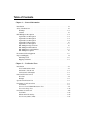
Agilent 75000 Series B
Agilent E1351A/52A/53A/57A/58A
FET Multiplexers
Service Manual
Enclosed is the Service Manual for the Agilent E1351A/52A/53A/57A/58A
FET Multiplexers. Insert this manual, along with any other VXIbus manuals
that you have, into the binder that came with your Agilent Mainframe.
*E1351-90011*
Manual Part Number: E1351-90011
Printed in Malaysia E0912
Certification
Agilent Technologies certifies that this product met its published specifications at the time of shipment from the factory. Agilent
Technologies further certifies that its calibration measurements are traceable to the United States National Institute of Standards and
Technology (formerly National Bureau of Standards), to the extent allowed by that organization’s calibration facility, and to the calibration
facilities of other International Standards Organization members.
Warranty
This Agilent Technologies product is warranted against defects in materials and workmanship for a period of one (1) year from date of
shipment. Duration and conditions of warranty for this product may be superseded when the product is integrated into (becomes a part
of) other Agilent products. During the warranty period, Agilent Technologies will, at its option, either repair or replace products which
prove to be defective.
For warranty service or repair, this product must be returned to a service facility designated by Agilent Technologies. Buyer shall prepay
shipping charges to Agilent and Agilent shall pay shipping charges to return the product to Buyer. However, Buyer shall pay all shipping
charges, duties, and taxes for products returned to Agilent from another country.
Agilent warrants that its software and firmware designated by Agilent for use with a product will execute its programming instructions
when properly installed on that product. Agilent does not warrant that the operation of the product, or software, or firmware will be
uninterrupted or error free.
Limitation Of Warranty
The foregoing warranty shall not apply to defects resulting from improper or inadequate maintenance by Buyer, Buyer-supplied products
or interfacing, unauthorized modification or misuse, operation outside of the environmental specifications for the product, or improper site
preparation or maintenance.
The design and implementation of any circuit on this product is the sole responsibility of the Buyer. Agilent does not warrant the Buyer’s
circuitry or malfunctions of Agilent products that result from the Buyer’s circuitry. In addition, Agilent does not warrant any damage that
occurs as a result of the Buyer’s circuit or any defects that result from Buyer-supplied products.
NO OTHER WARRANTY IS EXPRESSED OR IMPLIED. Agilent SPECIFICALLY DISCLAIMS THE IMPLIED WARRANTIES
OF MERCHANTABILITY AND FITNESS FOR A PARTICULAR PURPOSE.
Exclusive Remedies
THE REMEDIES PROVIDED HEREIN ARE BUYER’S SOLE AND EXCLUSIVE REMEDIES. Agilent SHALL NOT BE LIABLE
FOR ANY DIRECT, INDIRECT, SPECIAL, INCIDENTAL, OR CONSEQUENTIAL DAMAGES, WHETHER BASED ON CONTRACT, TORT, OR ANY OTHER LEGAL THEORY.
Notice
The information contained in this document is subject to change without notice. Agilent Technologies MAKES NO WARRANTY OF
ANY KIND WITH REGARD TO THIS MATERIAL, INCLUDING, BUT NOT LIMITED TO, THE IMPLIED WARRANTIES OF
MERCHANTABILITY AND FITNESS FOR A PARTICULAR PURPOSE. Agilent shall not be liable for errors contained herein or for
incidental or consequential damages in connection with the furnishing, performance or use of this material. This document contains
proprietary information which is protected by copyright. All rights are reserved. No part of this document may be photocopied, reproduced,
or translated to another language without the prior written consent of Agilent Technologies, Inc. Agilent assumes no responsibility for the
use or reliability of its software on equipment that is not furnished by Agilent.
U.S. Government Restricted Rights
The Software and Documentation have been developed entirely at private expense. They are delivered and licensed as "commercial
computer software" as defined in DFARS 252.227- 7013 (Oct 1988), DFARS 252.211-7015 (May 1991) or DFARS 252.227-7014 (Jun
1995), as a "commercial item" as defined in FAR 2.101(a), or as "Restricted computer software" as defined in FAR 52.227-19 (Jun 1987)(or
any equivalent agency regulation or contract clause), whichever is applicable. You have only those rights provided for such Software and
Documentation by the applicable FAR or DFARS clause or the Agilent standard software agreement for the product involved.
Agilent E1351A/52A/53A/57A/58A FET Multiplexer Module Service Manual
Edition 2 Rev 3
Copyright © 1996-2006 Agilent Technologies, Inc. All Rights Reserved.
i
Printing History
The Printing History shown below lists all Editions and Updates of this manual and the printing date(s). The first printing of the manual
is Edition 1. The Edition number increments by 1 whenever the manual is revised. Updates, which are issued between Editions, contain
replacement pages to correct the current Edition of the manual. Updates are numbered sequentially starting with Update 1. When a new
Edition is created, it contains all the Update information for the previous Edition. Each new Edition or Update also includes a revised copy
of this printing history page. Many product updates or revisions do not require manual changes and, conversely, manual corrections may
be done without accompanying product changes. Therefore, do not expect a one-to-one correspondence between product updates and
manual updates.
Edition 1 . . . . . . . . . . . . . . . . . . . . . . . . . . . . . . . . . . . . . . . . . . . . . . . . May 1993
Edition 2 (Part Number E1351-90011). . . . . . . . . . . . . . . . . . . . . . . . . June 1996
Edition 2 Rev 2 (Part Number E1351-90011) . . . . . . . . . . . . . . . . . . . June 2006
Edition 2 Rev 3 (Part Number E1351-90011) . . . . . . . . . . . . . . September 2012
Safety Symbols
Instruction manual symbol affixed to product.
Indicates that the user must refer to the manual for specific WARNING or CAUTION
information to avoid personal injury or damage to the product.
Alternating current (AC).
Direct current (DC).
Indicates hazardous voltages.
Indicates the field wiring terminal that must
be connected to earth ground before operating
the equipment—protects against electrical
shock in case of fault.
or
WARNING
Frame or chassis ground terminal—typically
connects to the equipment’s metal frame.
CAUTION
Calls attention to a procedure, practice, or condition that could cause bodily injury or death.
Calls attention to a procedure, practice, or condition that could possibly cause damage to
equipment or permanent loss of data.
WARNINGS
The following general safety precautions must be observed during all phases of operation, service, and repair of this product.
Failure to comply with these precautions or with specific warnings elsewhere in this manual violates safety standards of design,
manufacture, and intended use of the product. Agilent Technologies assumes no liability for the customer’s failure to comply with
these requirements.
Ground the equipment: For Safety Class 1 equipment (equipment having a protective earth terminal), an uninterruptible safety earth
ground must be provided from the mains power source to the product input wiring terminals or supplied power cable.
DO NOT operate the product in an explosive atmosphere or in the presence of flammable gases or fumes.
For continued protection against fire, replace the line fuse(s) only with fuse(s) of the same voltage and current rating and type.
DO NOT use repaired fuses or short-circuited fuse holders.
Keep away from live circuits: Operating personnel must not remove equipment covers or shields. Procedures involving the removal of
covers or shields are for use by service-trained personnel only. Under certain conditions, dangerous voltages may exist even with the
equipment switched off. To avoid dangerous electrical shock, DO NOT perform procedures involving cover or shield removal unless you
are qualified to do so.
DO NOT operate damaged equipment: Whenever it is possible that the safety protection features built into this product have been
impaired, either through physical damage, excessive moisture, or any other reason, REMOVE POWER and do not use the product until
safe operation can be verified by service-trained personnel. If necessary, return the product to an Agilent Technologies Sales and Service
Office for service and repair to ensure that safety features are maintained.
DO NOT service or adjust alone: Do not attempt internal service or adjustment unless another person, capable of rendering first aid and
resuscitation, is present.
DO NOT substitute parts or modify equipment: Because of the danger of introducing additional hazards, do not install substitute parts
or perform any unauthorized modification to the product. Return the product to an Agilent Technologies Sales and Service Office for
service and repair to ensure that safety features are maintained.
ii
Declaration of Conformity
Declarations of Conformity for this product and for other Agilent products may be downloaded from the Internet. There are two methods to obtain
the Declaration of Conformity:
•
Go to http://regulations.corporate.agilent.com/DoC/search.htm. You can then search by product number to find the latest Declaration
of Conformity.
• Alternately, you can go to the product web page (e.g., www.agilent.com/find/E1351A), click on the Document Library tab then
scroll down until you find the Declaration of Conformity link.
iv
Agilent 75000 Series B Service Documentation
Suggested Sequence to Use Manuals
Manual Descriptions
Installation and Getting Started Guide. This manual contains step-by-step instructions for all aspects of
plug-in module and mainframe installation. Introductory programming information and examples are also
included.
Mainframe User’s Manual. This manual contains programming information for the mainframe, front panel
operation information (for the Agilent E1301B mainframe), and general programming information for
instruments installed in the mainframe.
Plug-In Module User’s Manuals. These manuals contain plug-in module programming and configuration
information. Each manual contains examples for the most-used module functions, and a complete SCPI
command reference for the plug-in module.
Mainframe Service Manual. This manual contains service information for the mainframe. It contains
information for ordering replaceable parts and exchanging assemblies. Information and procedures for
performance verification, adjustment, preventive maintenance, troubleshooting, and repair are also included.
Plug-In Module Service Manuals. These manuals contain plug-in module service information. Each manual
contains information for exchanging the module and/or ordering replaceable parts. Depending on the module,
information and procedures for functional verification, operation verification, performance verification,
adjustment, preventive maintenance, troubleshooting, and repair are also provided.
v
What’s in this Manual
Manual Overview
This manual shows how to service the Agilent E1351A, E1352A, E1353A, E1357A, and E1358A FET
Multiplexers. Consult the appropriate FET Multiplexer User’s Manual for additional information on installing,
configuring, and operating each FET Multiplexer. Consult the appropriate mainframe user’s manual for
information on configuring and operating the mainframe.
Manual Content
Chapter
Title
Content
1
General
Information
Provides a basic description and lists the test equipment required for service.
2
Verification
Tests
Functional verification, operation verification, and performance verification tests.
3
Replaceable
Parts
Lists replaceable parts for the module.
4
Service
Procedures to aid in fault isolation and repair of the module.
vi
Table of Contents
Chapter 1 — General Information
Introduction . . . . . . . . . . . . . . . . . . . . . . . . . . . . . . . . . . . . . . . 1-1
Safety Considerations . . . . . . . . . . . . . . . . . . . . . . . . . . . . . . . . . . 1-2
Warnings . . . . . . . . . . . . . . . . . . . . . . . . . . . . . . . . . . . . . . 1-2
Cautions . . . . . . . . . . . . . . . . . . . . . . . . . . . . . . . . . . . . . . . 1-3
FET Multiplexer Description . . . .
Agilent E1351A Description . .
Agilent E1352A Description . .
Agilent E1353A Description . .
Agilent E1357ADescription . . .
Agilent E1358A Description . .
FET Multiplexer Specifications .
FET Multiplexer Environment .
FET Multiplexer Serial Numbers
FET Multiplexer Options . . . .
.
.
.
.
.
.
.
.
.
.
.
.
.
.
.
.
.
.
.
.
.
.
.
.
.
.
.
.
.
.
.
.
.
.
.
.
.
.
.
.
.
.
.
.
.
.
.
.
.
.
.
.
.
.
.
.
.
.
.
.
.
.
.
.
.
.
.
.
.
.
.
.
.
.
.
.
.
.
.
.
.
.
.
.
.
.
.
.
.
.
.
.
.
.
.
.
.
.
.
.
.
.
.
.
.
.
.
.
.
.
.
.
.
.
.
.
.
.
.
.
.
.
.
.
.
.
.
.
.
.
.
.
.
.
.
.
.
.
.
.
.
.
.
.
.
.
.
.
.
.
.
.
.
.
.
.
.
.
.
.
.
.
.
.
.
.
.
.
.
.
.
.
.
.
.
.
.
.
.
.
.
.
.
.
.
.
.
.
.
.
.
.
.
.
.
.
.
.
.
.
.
.
.
.
.
.
.
.
.
.
.
.
.
.
.
.
.
.
.
.
.
.
.
.
.
.
.
.
.
.
.
.
.
.
.
.
.
.
.
.
.
.
.
.
.
.
.
.
.
.
.
.
.
.
.
.
.
.
.
.
1-4
1-4
1-4
1-4
1-5
1-5
1-5
1-5
1-5
1-5
Recommended Test Equipment . . . . . . . . . . . . . . . . . . . . . . . . . . . . . 1-6
Inspection/Shipping . . . . . . . . . . . . . . . . . . . . . . . . . . . . . . . . . . . 1-6
Initial Inspection . . . . . . . . . . . . . . . . . . . . . . . . . . . . . . . . . . . 1-6
Shipping Guidelines . . . . . . . . . . . . . . . . . . . . . . . . . . . . . . . . . 1-8
Chapter 2 — Verification Tests
Introduction . . . . . . . . . .
Test Conditions/Procedures
Performance Test Record .
Verification Test Examples
.
.
.
.
.
.
.
.
.
.
.
.
.
.
.
.
.
.
.
.
.
.
.
.
.
.
.
.
.
.
.
.
.
.
.
.
.
.
.
.
.
.
.
.
.
.
.
.
.
.
.
.
.
.
.
.
.
.
.
.
.
.
.
.
.
.
.
.
.
.
.
.
.
.
.
.
.
.
.
.
.
.
.
.
.
.
.
.
.
.
.
.
.
.
.
.
.
.
.
.
.
.
.
.
.
.
.
.
.
.
.
.
.
.
.
.
2-1
2-1
2-1
2-1
FunctionalVerification Test . . . . . . . . . . . . . . . . . . . . . . . . . . . . . . . 2-2
Procedure . . . . . . . . . . . . . . . . . . . . . . . . . . . . . . . . . . . . . . 2-2
Example . . . . . . . . . . . . . . . . . . . . . . . . . . . . . . . . . . . . . . . 2-2
Operation Verification Test . . . . . . . . . . . . . . . . . . . . . . . . . . . . . . . 2-3
Performance Verification Tests . . . . . . . .
Test Fixture . . . . . . . . . . . . . . . .
Test 2-1: Closed Channel Resistance Test
Test 2-2: Leakage Test . . . . . . . . . . .
.
.
.
.
.
.
.
.
.
.
.
.
.
.
.
.
.
.
.
.
.
.
.
.
.
.
.
.
.
.
.
.
.
.
.
.
.
.
.
.
.
.
.
.
.
.
.
.
.
.
.
.
.
.
.
.
.
.
.
.
.
.
.
.
.
.
.
.
.
.
.
.
.
.
.
.
.
.
.
.
.
.
.
.
2-3
2-3
2-4
2-12
Performance Test Record . . .
Test Limits . . . . . . . . .
Measurement Uncertainty .
Test Accuracy Ratio (TAR)
.
.
.
.
.
.
.
.
.
.
.
.
.
.
.
.
.
.
.
.
.
.
.
.
.
.
.
.
.
.
.
.
.
.
.
.
.
.
.
.
.
.
.
.
.
.
.
.
.
.
.
.
.
.
.
.
.
.
.
.
.
.
.
.
.
.
.
.
.
.
.
.
.
.
.
.
.
.
.
.
.
.
.
.
2-22
2-22
2-22
2-23
.
.
.
.
.
.
.
.
.
.
.
.
.
.
.
.
.
.
.
.
.
.
.
.
.
.
.
.
.
.
.
.
Chapter 3 — Replaceable parts
Introduction . . . . . . . . . . . . . . . . . . . . . . . . . . . . . . . . . . . . . . . 3-1
Replaceable Parts Lists . . . . . . . . . . . . . . . . . . . . . . . . . . . . . . . . . 3-1
Exchange Assembly . . . . . . . . . . . . . . . . . . . . . . . . . . . . . . . . . . . 3-1
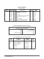
Mechanical Parts Locators . . . . . . . . . . . . . . . . . . . . . . . . . . . . . . . . 3-5
Chapter 4 — Service
Introduction . . . . . . . . . . .
Equipment Required . . . . .
Service Aids . . . . . . . . .
FET Multiplexer Description
.
.
.
.
.
.
.
.
.
.
.
.
.
.
.
.
.
.
.
.
.
.
.
.
.
.
.
.
.
.
.
.
.
.
.
.
.
.
.
.
.
.
.
.
.
.
.
.
.
.
.
.
.
.
.
.
.
.
.
.
.
.
.
.
.
.
.
.
.
.
.
.
.
.
.
.
.
.
.
.
.
.
.
.
.
.
.
.
.
.
.
.
.
.
.
.
.
.
.
.
.
.
.
.
.
.
.
.
.
.
.
.
4-1
4-1
4-1
4-1
Repair Strategy . . . . . . . . . . . . . . . . . . . . . . . . . . . . . . . . . . . . . 4-6
Troubleshooting Techniques
Identifying the Problem .
Making Visual Checks . .
Testing the Module . . .
.
.
.
.
.
.
.
.
.
.
.
.
.
.
.
.
.
.
.
.
.
.
.
.
.
.
.
.
.
.
.
.
.
.
.
.
.
.
.
.
.
.
.
.
.
.
.
.
.
.
.
.
.
.
.
.
.
.
.
.
.
.
.
.
.
.
.
.
.
.
.
.
.
.
.
.
.
.
.
.
.
.
.
.
.
.
.
.
.
.
.
.
.
.
.
.
.
.
.
.
.
.
.
.
.
.
.
.
.
.
.
.
.
.
.
.
.
.
.
.
4-6
4-6
4-7
4-7
Repair and Maintenance Guidelines .
ESD Precautions . . . . . . . . .
Soldering Printed Circuit Boards
Post-Repair Safety Checks . . . .
.
.
.
.
.
.
.
.
.
.
.
.
.
.
.
.
.
.
.
.
.
.
.
.
.
.
.
.
.
.
.
.
.
.
.
.
.
.
.
.
.
.
.
.
.
.
.
.
.
.
.
.
.
.
.
.
.
.
.
.
.
.
.
.
.
.
.
.
.
.
.
.
.
.
.
.
.
.
.
.
.
.
.
.
.
.
.
.
.
.
.
.
.
.
.
.
.
.
.
.
.
.
.
.
4-8
4-8
4-8
4-8
Appendix A— Verification Tests - C Programs
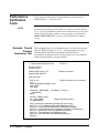
Functional Verification Test . . . . . . . . . . . . . . . . . . . . . . . . . . . . . . . A-1
Example: Self Test . . . . . . . . . . . . . . . . . . . . . . . . . . . . . . . . . A-1
Performance Verification Tests . . . . . . . . . . . . . . . . . . . . . . . . . . . . . A-2
Example: Closed Channel Resistance Test . . . . . . . . . . . . . . . . . . . . . A-2
Example: Leakage Current Test . . . . . . . . . . . . . . . . . . . . . . . . . . A-6
Chapter 1
General Information
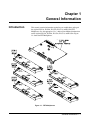
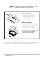
Introduction
This manual contains information required to test, troubleshoot, and repair
the Agilent E1351A, E1352A, E1353A, E1357A, and E1358A FET
Multiplexers. See the appropriate User’s Manual for additional information
on the Agilent E1351A, E1352A, E1353A, E1357A, and E1358A. Figure
1-1 shows the FET Multiplexers.
Figure 1-1. FET Multiplexers
General Information 1-1
Safety
Considerations
This product is a Safety Class I instrument that is provided with a protective
earth terminal when installed in the mainframe. Check the mainframe, FET
Multiplexer, Terminal Block, and all related documentation for safety
markings and instructions before operation or service.
Refer to the WARNINGS page (page ii) in this manual for a summary of
safety information. Safety information for preventive maintenance, testing,
and service follows and is also found throughout this manual.
Warnings
WARNING
This section contains WARNINGS which must be followed for your
protection when performing equipment maintenance or repair.
SERVICE-TRAINED PERSONNEL ONLY. The information in this
manual is for service-trained personnel who are familiar with
electronic circuitry and are aware of the hazards involved. To
avoid personal injury or damage to the instrument, do not
perform procedures in this manual or do any servicing unless
you are qualified to do so.
CHECK MAINFRAME POWER SETTINGS. Before applying
power, verify that the mainframe setting matches the line
voltage and that the correct fuse is installed. An uninterruptible
safety earth ground must be provided from the main power
source to the supplied power cord set.
GROUNDING REQUIREMENTS. Interruption of the protective
(grounding) conductor (inside or outside the mainframe) or
disconnecting the protective earth terminal will cause a
potential shock hazard that could result in personal injury.
(Grounding one conductor of a two-conductor outlet is not
sufficient protection.)
IMPAIRED PROTECTION. Whenever it is likely that instrument
protection has been impaired, the mainframe must be made
inoperative and be secured against any unintended operation.
REMOVE POWER IF POSSIBLE. Some procedures in this
manual may be performed with power supplied to the
mainframe while protective covers are removed. Energy
available at many points may, if contacted, result in personal
injury. (If maintenance can be performed without power applied,
the power should be removed.)
1-2 General Information
WARNING
USING AUTOTRANSFORMERS. If the mainframe is to be
energized via an autotransformer (for voltage reduction) make
sure the common terminal is connected to neutral (that is, the
grounded side of the main’s supply).
CAPACITOR VOLTAGES. Capacitors inside the mainframe may
remain charged even when the mainframe has been
disconnected from its source of supply.
USE PROPER FUSES. For continued protection against fire
hazard, replace the line fuses only with fuses of the same
current rating and type (such as normal blow, time delay, etc.).
Do not use repaired fuses or short-circuited fuseholders.
Cautions
CAUTION
This section contains CAUTIONS which must be followed to avoid damage
to the equipment when performing instrument maintenance or repair.
MAXIMUM VOLTAGE/CURRENT. The maximum voltage that may
be applied between any connector pin and any other point, shield, or
chassis is 15 VPeak.
STATIC ELECTRICITY. Static electricity is a major cause of
component failure. To prevent damage to the electrical components in
the FET Multiplexer, observe anti-static techniques whenever working
on a FET Multiplexer.
General Information 1-3
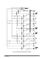
FET Multiplexer
Description
The Agilent E1351A, E1352A, E1353A, E1357A, and E1358A FET
Multiplexer is an "instrument" in a VXIbus mainframe. As such, each FET
Multiplexer is assigned an error queue, input and output buffers, and a status
register.
NOTE
Instruments are based on the logical addresses of the plug-in modules. See
the Agilent 75000 Series B Installation and Getting Started Guide to set the
addresses to create an instrument.
The FET Multiplexer Module consists of a component assembly and a
terminal block. There are five different terminal blocks, one for each
application. The component assembly is the same for all applications. The
applications supported by the component assembly are:
•
•
•
•
•
Agilent E1351A 16-Channel FET Multiplexer
Agilent E1352A 32-Channel Single Ended FET Multiplexer
Agilent E1353A 16-Channel Thermocouple FET Multiplexer
Agilent E1357A 8-Channel 120 Ω Strain Gage FET Multiplexer
Agilent E1358A 8-Channel 350 Ω Strain Gage FET Multiplexer
Each terminal block configures the component assembly to the appropriate
type of switch. The terminal card also contains the model identification code
and installation of the terminal card before applying mainframe power
ensures that the type of switch is properly identified. Optionally, the model
identification can be set on the component assembly to allow it to be
correctly identified without a terminal card installed.
Agilent E1351A
Description
The Agilent E1351A provides high speed switching for up to 16 channels.
The channels are numbered 00 to 15. Each channel provides connections for
High (HI), Low (LO), and Guard (G), although only High and Low are
switched. Guard for each channel is connected to chassis ground through a
10 k Ω resistor.
Agilent E1352A
Description
The Agilent E1352A provides high-speed switching for up to 32 channels.
The channels are numbered 00 to 31. A High (HI) connection is provided
for each channel. Low (LO) and Guard (G) are common for all channels.
Agilent E1353A
Description
1-4 General Information
The Agilent E1353A is identical to the Agilent E1351A, but contains a
temperature reference thermistor on the terminal block to allow
thermocouple temperature measurements when combined with either the
Agilent E1326A or E1411B Multimeters.
Agilent E1357A
Description
The Agilent E1357A provides up to eight channels of strain gage switching.
Strain gage measurements are supported in 1/4 bridge, 1/2 bridge, and full
bridge measurements with 120 Ω completion resistors. A strain gage
excitation power supply is also provided.
Agilent E1358A
Description
The Agilent E1358A is identical to the Agilent E1357A except the strain
gage completion resistors are 350 Ω..
FET Multiplexer
Specifications
See Appendix A of the appropriate User’s Manual for Agilent E1351A,
E1352A, E1353A, E1357A, and E1358A specifications. These
specifications are the performance standards or limits against which the
instrument may be tested.
FET Multiplexer
Environment
The recommended operating environment for the Agilent E1351A, E1352A,
E1353A, E1357A, and E1358A FET Multiplexer is:
Environment
FET Multiplexer
Serial Numbers
Temperature
Humidity
Operating
0oC to +55oC
<65% relative (0oC to +40oC)
Storage and
Shipment
-40oC to +75oC
<65% relative (0oC to +40oC)
FET Multiplexers covered by this manual are identified by a serial number
prefix listed on the title page. Agilent Technologies uses a two-part serial
number in the form XXXXAYYYYY, where XXXX is the serial prefix, A
is the country of origin (A=USA), and YYYYY is the serial suffix. The
serial number prefix identifies a series of identical instruments. The serial
number suffix is assigned sequentially to each instrument.
The serial number plate is located on the backplane connector. If the serial
number prefix of your instrument is greater than the one listed on the title
page, a Manual Update (as required) will explain how to adapt this manual
to your instrument.
FET Multiplexer
Options
There are no electrical or mechanical options available for the Agilent
E1351A, E1352A, E1353A, E1357A, or E1358A FET Multiplexers.
General Information 1-5
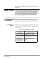
Recommended
Test Equipment
Table 1-1 lists the test equipment recommended for testing, adjusting, and
servicing the FET Multiplexers. Essential requirements for each piece of test
equipment are described in the Requirements column.
Table 1-1. Recommended Test Equipment
Instrument
Requirements
Recommended
Model
Use*
Controller, GPIB
GPIB compatibility as defined by IEEE
Standard 488-1987 and the identical
ANSI Standard MC1.1: SH1, AH1, T2,
TE0, L2, LE0, SR0, RL0, PP0, DC0,
DT0, and C1, 2, 3, 4, 5.
HP 9000 Series 300
or
IBM Compatible PC with
BASIC
F,O,
P,T
Mainframe
Compatible with FET Multiplexer
Agilent E1300B,
E1301B, E1302A or
E1401B, E1421A
(requires E1405A/B)
F,O,
P,T
Digital Multimeter
2-Wire Ohms (up to 10 kΩ )
DC Volts (to 0.01 mV)
Agilent 3458A or
Agilent 34401A
O,P,T
Power Supply
+10 Vdc ± 0.1 V
Agilent 6214C
P, T
Resistor
100 k Ω ± 1%
Agilent PN 0757-0465
P, T
* F = Functional Verification Tests, O = Operation Verification Tests, P = Performance Verification Tests, T = Troubleshooting
Inspection/
Shipping
Initial
Inspection
WARNING
1-6 General Information
This section contains initial (incoming) inspection and shipping guidelines
for the FET Multiplexer.
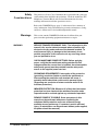
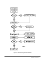
Use the steps in Figure 1-2 as guidelines to perform initial inspection of a
FET Multiplexer. Performance Verification tests are optional.
To avoid possible hazardous electrical shock, do not perform
electrical tests if there are signs of shipping damage to the
shipping container or to the instrument.
Notify Agilent and carrier.
Notify Agilent
Figure 1-2. Initial (Incoming) Inspection Guidelines
General Information 1-7
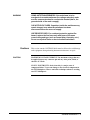
Shipping
Guidelines
Follow the steps in Figure 1-3 to return a FET Multiplexer to an Agilent
Technologies Sales and Support Office or Service Center.
1 Prepare the FET Multiplexer
• Remove user wiring from the module
• Attach tag to module/pod that identifies
- Owner
- Model Number/Serial Number
- Service Required
• Place tagged device in approved anti-static bag
2 Package the FET Multiplexer
• Place packaged FET Multiplexer in shipping carton*
• Place 75 to 100 mm (3 to 4 inches) of shockabsorbing material around the FET Multiplexer
• Seal the shipping carton securely
• Mark the shipping carton FRAGILE
3 Ship the FET Multiplexer to Agilent Technologies
• Place address label on shipping carton
• Send carton to Agilent Technologies
Figure 1-3. Packaging/Shipping Guidelines
* We recommend that you use the same shipping materials as those used in factory packaging (available from Agilent Technologies).
For other (commercially-available) shipping materials, use a double wall-carton with minimum 2.4 MPa (350 psi) test.
1-8 General Information
Chapter 2
Verification Tests
Introduction
This chapter describes the verification tests for the Agilent E1351A,
E1352A, E1353A, E1357A, and E1358A. The three levels of test
procedures described in this chapter are used to verify that the Agilent
E1351A, E1352A, E1353A, E1357A, and E1358A:
• is functional (Functional Verification Test)
• meets selected testable specifications (Operation Verification)
• meets all testable specifications (Performance Verification)
Test Conditions/
Procedures
Performance
Test Record
Verification Test
Examples
See Table 1-1 for test equipment requirements. You should complete the
Performance Verification tests at least once a year. For heavy use or severe
operating environments, perform the tests more often. The verification tests
assume that the person performing the tests understands how to operate the
mainframe, the FET Multiplexer, and the specified test equipment. The test
procedures do not specify equipment settings for test equipment except in
general terms. It is assumed that a qualified, service-trained technician will
select and connect the fixtures, adapters, and probes required for the test.
The results of each Performance Verification test may be recorded in
Table 2-1, Performance Test Record, at the end of this chapter. You can
make a copy of this form, if desired.
Each verification test procedure includes an example program that performs
the test. All example programs assume the following configuration:
•
•
•
•
•
HP 9000 Series 200/300 computer
BASIC programming language
FET Multiplexer address 70914
FET Multiplexer card number 1
Agilent 3458A Digital Multimeter (DMM)
Verification Tests 2-1
Functional
Verification
Test
The Functional Verification Test for the Agilent E1351A, E1352A,
E1353A, E1357A, and E1358A FET Multiplexers consists of sending the
*IDN? command and checking the response. This test can be used to verify
that the FET Multiplexer is connected properly and is responding to a basic
command.
Procedure
1. Verify that the FET Multiplexer is properly installed in the mainframe
2. Verify that the terminal block or test fixture is properly connected to
the Multiplexer
3. Verify that the mainframe has passed its power-on test
4. Send *IDN? to the FET Multiplexer (see example following)
5. The return should be as follows (revision number may vary):
HEWLETT-PACKARD,SWITCHBOX,0,A.07.00
NOTES
Example
If the primary address setting, secondary address setting, or the interface
select code is set incorrectly, the FET Multiplexer will not respond. Verify
proper address selection before troubleshooting.
An example follows which uses an HP 9000 Series 300 computer with
BASIC and a FET Multiplexer address of 70914.
10
20
30
40
DIM A$[100]
OUTPUT 70914;"*IDN?"
ENTER 70914;A$
PRINT A$
50 END
2-2 Verification Tests
!Send the ID command
!Get response
Operation
Verification
Test
The procedures in this section are used to provide a high level of confidence
that the FET Multiplexer is meeting published specifications. The Operation
Verification Test is a subset of the Performance Verification Tests and is
suitable for checkout after performing repairs.
The Operation Verification Test is performed by completing the Closed
Channel Resistance Test (Test 2-1) as described in the Performance
Verification Test procedures. This test is usually sufficient to verify that the
FET Multiplexer is meeting its specifications.
Performance
Verification
Tests
The procedure in this section is used to test the FET Multiplexer’s electrical
performance using the specifications in Appendix A — Specifications of the
appropriate FET Multiplexer User’s Manual as the performance standard.
There are two performance verification tests; Test 2-1: Closed channel
Resistance Test, and Test 2-2: Leakage Test. These tests are suitable for
incoming inspection, troubleshooting, and preventive maintenance.
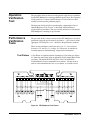
Test Fixture
A Test Fixture is required to run the Performance Verification tests. Figure
2-1 shows the connections using an Agilent E1351A Terminal Block for the
test fixture. The Agilent E1352A, E11353A, E1357A and E1358A
Terminal Blocks are not recommended as test fixtures. You may want to
order an extra terminal block to use as a test fixture, so you don’t have to
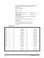
Figure 2-1. FET Multiplexer Test Fixture
Verification Tests 2-3
re-wire each time the tests are performed. The Agilent E1351A terminal
block and case assembly part number is E1351-80001.
Test 2-1: Closed
Channel
Resistance Test
HI Channel
Measurements
This test first verifies that no FET switches are stuck in the on condition and
then verifies that all channels meet the closed channel resistance
specification for the FET Multiplexer. The channel HI, channel LO, A Tree,
and B Tree switches are all independently tested.
1. Make Hardware Connections
• Turn mainframe power OFF
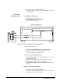
• Connect DMM as shown in Figure 2-2
• Turn mainframe power ON
Agilent E1300B/E1301B
Figure 2-2. HI Channel Resistance Test Connections
2. Check for Stuck Channels
• Send *RST to the FET Multiplexer to open all channels
• Trigger the DMM with TRIG SGL and note reading
• Verify the reading is greater than 10 kΩ
3. Check HI Closed Channel Resistance
• Send CLOS (@nn00) to close channel 00, where nn is the card
number (typically 01)
• Trigger the DMM with TRIG SGL and note the reading
• Enter the result in Table 2-1 for channel 00 HI
• Send OPEN (@nn00) to open channel 00, where nn is the card
number
4. Repeat for Channels 01 through 15
2-4 Verification Tests
• Repeat step 3 for channels 01 through 15
• Use CLOS (@nncc), where nn is the card number and cc is the
channel number
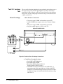
LO Channel
Measurements
1. Make Hardware Connections
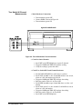
• Turn mainframe power OFF
• Connect DMM as shown in Figure 2-3
• Turn mainframe power ON
Agilent E1300B/E1301B
Figure 2-3. LO Channel Resistance Test Connections
2. Check for Stuck Channels
• Send *RST to the FET Multiplexer to open all channels
• Trigger the DMM with TRIG SGL and note reading
• Verify the reading is greater than 10 kΩ
3. Check LO Closed Channel Resistance
• Send CLOS (@nn00) to close channel 00, where nn is the card
number (typically 01)
• Trigger the DMM with TRIG SGL and note the reading
• Enter the result in Table 2-1 for channel 00 LO
• Send OPEN (@nn00) to open channel 00, where nn is the card
number
4. Repeat for Channels 01 through 15
• Repeat step 3 for channels 01 through 15
• Use CLOS (@nncc) and OPEN (@nncc), where nn is the card
number and cc is the channel number
Verification Tests 2-5
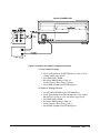
Tree Switch HI Channel
Measurements
1. Make Hardware Connections
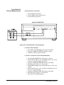
• Turn mainframe power OFF
• Connect DMM as shown in Figure 2-4
• Turn mainframe power ON
Agilent E1300B/E1301B
Figure 2-4. Tree HI Resistance Test Connections
2. Check for Stuck Channels
• Send *RST to the FET Multiplexer to open all channels
• Trigger the DMM with TRIG SGL and note reading
• Verify the reading is greater than 10 kΩ
3. Check Tree Switch HI Closed Channel Resistance
• Send SCAN:PORT ABUS to enable the tree switches
• Send CLOS (@nn00) to close channel 00 and the A tree switch,
where nn is the card number (typically 01)
• Trigger the DMM with TRIG SGL and note the reading
• Enter the result in Table 2-1 for Tree A HI
• Send OPEN (@nn00) to open channel 00, where nn is the card
number
• Send CLOS (@nn15) to close channel 15 and the B tree switch,
where nn is the card number
• Trigger the DMM with TRIG SGL and note the reading
• Enter the result in Table 2-1 for Tree B HI
• Send *RST to the FET Multiplexer
2-6 Verification Tests
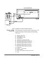
Tree Switch LO
Channel Measurements
1. Make Hardware Connections
• Turn mainframe power OFF
• Connect DMM as shown in Figure 2-5
• Turn mainframe power ON
Agilent E1300B/E1301B
Figure 2-5. Tree LO Resistance Test Connections
2. Check for Stuck Channels
• Send *RST to the FET Multiplexer to open all channels
• Trigger the DMM with TRIG SGL and note reading
• Verify the reading is greater than 10 kΩ
3. Check Tree Switch LO Closed Channel Resistance
• Send SCAN:PORT ABUS to enable the tree switches
• Send CLOS (@nn00) to close channel 00 and the A tree switch,
where nn is the card number (typically 01)
• Trigger the DMM with TRIG SGL and note the reading
• Enter the result in Table 2-1 for Tree A LO
• Send OPEN (@nn00) to open channel 00, where nn is the card
number
• Send CLOS (@nn15) to close channel 15 and the B tree switch,
where nn is the card number
• Trigger the DMM with TRIG SGL and note the reading
• Enter the result in Table 2-1 for Tree B LO
• Send *RST to the FET Multiplexer
Verification Tests 2-7
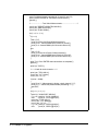
Example: Closed
Channel Resistance
Test
This example performs a closed channel resistance test of all measurement
paths. If a FET on resistance is >3.1 kΩ , the program prints a message
indicating which channel has failed. Before the closed channel
measurement, the program checks for stuck channels. If a stuck channel is
found, the program prints a message and halts.
10! RE-SAVE "CLOS_TEST"
20
ASSIGN @Dmm TO 722
30
ASSIGN @Mux TO 70914
40
DISP CHR$(129)
50
DIM Result(1,15),Tree(1,1),Path$(1)[4], Cc$[2],Ch$[2]
60
DATA HI,LO
70 READ Path$(*)
80
Cc$ = "01"
! Card number
90
!
100 ! Start test
110 !
120 CLEAR SCREEN
130 PRINT "Install Component Assembly and Test Fixture"
140 PRINT
150 PRINT " 1. Turn mainframe and Agilent 3458A DMM power OFF"
160 PRINT " 2. Connect GPIB cable between mainframe and DMM"
170 PRINT " 3. Install component assembly into mainframe"
180 PRINT " 4. Attach test fixture to component assembly"
190 PRINT " 5. Turn mainframe and DMM power ON"
200 PRINT " 6. Press Continue when ready to begin testing"
210 PAUSE
220 !
230 ! Measure closed channel resistance
240 !
250 FOR I = 0 TO 1
260
CLEAR SCREEN
270
PRINT TABXY(1,1), "Channel ";Path$(I);" to Direct ";Path$(I);"
Measurements"
280
PRINT TABXY(1,3),"Connect DMM Input HI lead to Channel
";Path$(I)
290
300
310
320
330
340
350
360
2-8 Verification Tests
PRINT TABXY(1,4),"Connect DMM Input LO lead to Direct ";Path$(I)
DISP "Press Continue when connections are complete"
PAUSE
OUTPUT @Dmm;"PRESET NORM;FUNC OHM"
OUTPUT @Mux;"*RST"
!
! Check for stuck channels
!
370
OUTPUT @Dmm;"TRIG SGL"
380
ENTER @Dmm;Value
390
IF Value<10000 THEN
400
CLEAR SCREEN
410
PRINT "Measurement indicates a stuck channel"
420
PRINT "Correct the problem before proceeding"
430
STOP
440
END IF
450
CLEAR SCREEN
460
FOR J = 0 TO 15
470
IF J<10 THEN
480
Ch$="0"&VAL$(J)
490
ELSE
500
Ch$=VAL$(J)
510
END IF
520
OUTPUT @Mux;"CLOS (@"&Cc$&Ch$&")"
530
OUTPUT @Dmm;"TRIG SGL"
540
ENTER @Dmm;Result(I,J)
550
OUTPUT @Mux;"OPEN (@"&Cc$&Ch$&")"
560
IF Result(I,J)>3100 THEN
570
PRINT "Resistance for channel ";J;" ";
Path$(I);" is > 3.1 kOhms"
580
END IF
590
NEXT J
600
PRINT "Measurements complete for channel ";Path$(I)
610
IF I=0 THEN
620
DISP "Press Continue for channel ";Path$(I+1);" measurements"
630
PAUSE
640
END IF
650 NEXT I
660 PRINT "Measurements complete for channel HI and LO"
670 DISP "Press Continue for Tree Switch measurements"
680 PAUSE
690 !
700 ! Tree Switch measurements
710 !
720 FOR I = 0 TO 1
730
CLEAR SCREEN
740
PRINT TABXY(1,1), "Tree ";Path$(I);" to Direct ";Path$(I);
" measurements"
750
PRINT TABXY(1,3),"Connect DMM Input HI lead to Tree ";Path$(I)
760
PRINT TABXY(1,4),"Connect DMM Input LO lead to Direct ";Path$(I)
770
DISP "Press Continue when connections are complete"
Verification Tests 2-9
780
PAUSE
790
OUTPUT @Dmm;"PRESET NORM;FUNC OHM"
800
OUTPUT @Mux;"*RST"
810
!
820
! Check for stuck tree switches
830
!
840
OUTPUT @Dmm;"TRIG SGL"
850
ENTER @Dmm;Value
860
IF Value<10000 THEN
870
CLEAR SCREEN
880
PRINT "Measurement indicates a stuck tree switch"
890
PRINT "Correct the problem before proceeding"
900
STOP
910
END IF
920
CLEAR SCREEN
930
FOR J = 0 TO 1
940
IF J=0 THEN
950
Ch$="00"
960
ELSE
970
Ch$="15"
980
END IF
990
OUTPUT @Mux;"SCAN:PORT ABUS"
1000 OUTPUT @Mux;"CLOS (@"&Cc$&Ch$&")"
1010 OUTPUT @Dmm;"TRIG SGL"
1020 ENTER @Dmm;Tree(I,J)
1030 OUTPUT @Mux;"OPEN (@"&Cc$&Ch$&")"
1040 IF Tree(I,J)>3100 THEN
1050
IF Ch$="00" THEN
1060
PRINT "Resistance for A Tree Switch ";Path$(I);
" is > 3.1 kOhms"
1070
ELSE
1080
PRINT "Resistance for B Tree Switch ";Path$(I);
" is > 3.1 kOhms"
1090
END IF
1100 END IF
1110 NEXT J
1120 PRINT "Measurements complete for tree switch ";Path$(I)
1130 IF I=0 THEN
1140 DISP "Press Continue for Tree Switch ";Path$(I+1);
" measurements"
1150 PAUSE
1160 END IF
1170 NEXT I
2-10 Verification Tests
1180 PRINT "Closed channel resistance measurements complete"
1190 DISP "Press Continue to print measurement results"
1200 PAUSE
1210 CLEAR SCREEN
1220 !
1230 ! Print results
1240 !
1250 Format1:IMAGE "Channel ",DD,"
HI ",DDDDD," Ohms
",DDDDD," Ohms"
1260 Format2:IMAGE "Tree
",K,"
HI ",DDDDD," Ohms
",DDDDD," Ohms"
1270 PRINT "Closed channel resistance measurement results"
1280 FOR J=0 TO 15
1290 PRINT USING Format1;J,Result(0,J),Result(1,J)
1300 NEXT J
1310 PRINT
1320 PRINT USING Format2;"A",Tree(0,0),Tree(0,1)
1330 PRINT USING Format2;"B",Tree(1,0),Tree(1,1)
1340 END
LO
LO
Typical Result
Closed channel resistance measurement results
Channel
0
HI
989 Ohms
LO
1004 Ohms
Channel
1
HI
991 Ohms
LO
979 Ohms
Channel
2
HI
1001 Ohms
LO
989 Ohms
Channel
3
HI
990 Ohms
LO
1000 Ohms
Channel
4
HI
988 Ohms
LO
999 Ohms
Channel
5
HI
1002 Ohms
LO
995 Ohms
Channel
6
HI
1010 Ohms
LO
1000 Ohms
Channel
7
HI
998 Ohms
LO
998 Ohms
Channel
8
HI
1006 Ohms
LO
1008 Ohms
Channel
9
HI
1000 Ohms
LO
1002 Ohms
Channel
10
HI
995 Ohms
LO
988 Ohms
Channel
11
HI
999 Ohms
LO
990 Ohms
Channel
12
HI
1000 Ohms
LO
1000 Ohms
Channel
13
HI
989 Ohms
LO
991 Ohms
Channel
14
HI
979 Ohms
LO
989 Ohms
Channel
15
HI
1004 Ohms
LO
995 Ohms
Tree
A
HI
988 Ohms
LO
991 Ohms
Tree
B
HI
992 Ohms
LO
998 Ohms
Verification Tests 2-11
Test 2-2: Leakage
Test
HI to LO Leakage
The test verifies the input impedance by measuring the voltage drop across a
known resistor in series with the input impedance. Leakage is measured
from HI to LO, HI to Chassis, and LO to Chassis. Because of the solid state
nature of the switches and input protection, the leakage is measured at both
+10 Vdc and -10 Vdc.
1. Make Hardware Connections
• Turn power supply, DMM, and mainframe power OFF
• Connect DMM, power supply, and resistor as shown in Figure
2-6
• Turn power supply, DMM, and mainframe power ON
• Set power supply output to +10 Vdc ± 0.1 Vdc
Agilent E1300B/E1301B
Figure 2-6. Positive HI to LO Leakage Connections
2. Check Direct Terminals Leakage
• Send *RST to FET Multiplexer
• Send TRIG SGL to DMM
• Record the DMM reading in Table 2-1
Positive Polarity, HI to LO, Direct
• The DMM measurement should be less than 0.010 Vdc. A
measurement out of this range indicates a failure of the FET
Multiplexer and troubleshooting/repair/replacement procedures,
described in Chapter 4, should be performed before proceeding
with Test 2-2
2-12 Verification Tests
3. Check Channels Leakage
• Send CLOS(@nn00) to the FET Multiplexer to close channel
00, where nn is card number (typically 01)
• Send TRIG SGL to DMM
• Record the DMM reading in Table 2-1
Positive Polarity, HI to LO, Channels
• Send OPEN (@nn00) to the FET Multiplexer
4. Check Tree Leakage
• Send SCAN:PORT ABUS to the FET Multiplexer to enable the
Tree Switches
• Send CLOS(@nn00) to the FET Multiplexer to close channel
00 and Tree Switch A, where nn is the card number (typically
01)
• Send TRIG SGL to DMM
• Record the DMM reading in Table 2-1
Positive Polarity, HI to LO, Tree A
• Send OPEN (@nn00) to the FET Multiplexer
• Send CLOS(@nn15) to the FET Multiplexer to close channel
15 and Tree Switch B
• Send TRIG SGL to DMM
• Record the DMM reading in Table 2-1
Positive Polarity, HI to LO, Tree B
• Send *RST to the FET Multiplexer
5. Change Polarity
• Turn power supply and mainframe power OFF
• Connect DMM, power supply, and resistor as shown in
Figure 2-7
• Turn power supply and mainframe power ON
• Set power supply output to +10 Vdc ± 0.1 Vdc
6. Repeat Steps 2 through 4
• Record all results in Table 2-1 as
Negative Polarity, HI to LO
Verification Tests 2-13
Agilent E1300B/E1301B
Figure 2-7. Negative HI to LO Leakage Connections
HI to Chassis Leakage
1. Make Hardware Connections
• Turn power supply and mainframe power OFF
• Connect DMM, power supply, and resistor as shown in
Figure 2-8
• Turn power supply and mainframe power ON
2. Check Direct Terminals Leakage
• Send *RST to FET Multiplexer
• Send TRIG SGL to DMM
• Record the DMM reading in Table 2-1
Positive Polarity, HI to Chassis, Direct
• The DMM measurement should be less than 0.010 Vdc.
A measurement out of this range indicates a failure of the
FET Multiplexer
2-14 Verification Tests
Agilent E1300B/E1301B
Figure 2-8. Positive HI to Chassis Leakage Connections
3. Check Channels Leakage
• Send CLOS(@nn00) to the FET Multiplexer, where nn is the
channel number (typically 01)
• Send TRIG SGL to DMM
• Record the DMM reading in Table 2-1
Positive Polarity, HI to Chassis, Channels
• Send OPEN (@nn00) to the FET Multiplexer
4. Check Tree Leakage Current
• Send SCAN:PORT ABUS to the FET Multiplexer
• Send CLOS(@nn00) to the FET Multiplexer to close channel
00 and Tree A, where nn is the card number (typically 01)
• Send TRIG SGL to DMM
• Record the DMM reading in Table 2-1
Positive Polarity, HI to Chassis, Tree A
• Send OPEN (@nn00) to the FET Multiplexer
Verification Tests 2-15
• Send CLOS(@nn15) to the FET Multiplexer to close channel
15 and tree B
• Send TRIG SGL to DMM
• Record the DMM reading in Table 2-1
Positive Polarity, HI to Chassis, Tree B
• Send *RST to the FET Multiplexer
5. Change Polarity
• Turn power supply and mainframe power OFF
• Connect DMM, power supply, and resistor as shown in Figure
2-9
• Turn power supply and mainframe power ON
• Set power supply output to +10 Vdc ± 0.1 Vdc
6. Repeat Steps 2 through 4
• Record all results in Table 2-1 as
Negative Polarity, HI to Chassis
Agilent E1300B/E1301B
Figure 2-9. Negative HI to Chassis Leakage Connections
2-16 Verification Tests
LO to Chassis Leakage
1. Make Hardware Connections
• Turn power supply and mainframe power OFF
• Connect DMM, power supply, and resistor as shown in
Figure 2-10
• Turn power supply and mainframe power ON
Agilent E1300B/E1301B
Figure 2-10. Positive LO to Chassis Leakage Connections
2. Check Direct Terminals Leakage Current
• Send *RST to FET Multiplexer
• Send TRIG SGL to DMM
• Record the DMM reading in Table 2-1
Positive Polarity, LO to Chassis, Direct
• The DMM measurement should be less than 0.010 Vdc.
A measurement out of this range indicates a failure of the
FET Multiplexer.
3. Check Channels Leakage
• Send CLOS(@nn00) to the FET Multiplexer, where nn is the
card number (typically 01)
• Send TRIG SGL to DMM
Verification Tests 2-17
• Record the DMM reading in Table 2-1
Positive Polarity, LO to Chassis, Channels
• Send OPEN (@nn00) to the FET Multiplexer
4. Check Tree Leakage Current
• Send SCAN:PORT ABUS to the FET Multiplexer
• Send CLOS(@nn00) to the FET Multiplexer to close channel
00 and Tree A, where nn is the card number (typically 01)
• Send TRIG SGL to DMM
• Record the DMM reading in Table 2-1
Positive Polarity, LO to Chassis, Tree A
• Send OPEN (@nn00) to the FET Multiplexer
• Send CLOS(@nn15) to the FET Multiplexer to close channel
15 and Tree B
• Send TRIG SGL to DMM
• Record the DMM reading in Table 2-1
Positive Polarity, LO to Chassis, Tree B
• Send *RST to the FET Multiplexer
5. Change Polarity
• Turn power supply and mainframe power OFF
• Connect DMM, power supply, and resistor as shown in Figure
2-11
• Turn power supply and mainframe power ON
6. Repeat Steps 2 through 4
• Record all results in Table 2-1 as
Negative Polarity, LO to Chassis
2-18 Verification Tests
Agilent E1300B/E1301B
Figure 2-11. Negative LO to Chassis Leakage Connections
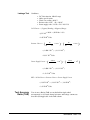
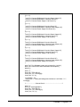
Example: Leakage
Current Test
This example performs a leakage test from HI to LO, HI to Chassis, and LO
to Chassis. If the leakage is too high (caused by a failure of the input
impedance), the test prints a message indicating which leakage path has
failed and halts.
10!
20
RE-SAVE "LEAK_TEST"
ASSIGN @Dmm TO 722
30
40
50
ASSIGN @Mux TO 70914
DISP CHR$(129)
DIM Result(5,3), Path$(5,3)[16],Cc$[2]
60
70
80
90
100
110
120
130
140
150
160
DATA Power Supply HI,Direct HI,LO,Direct LO
DATA Direct HI,Power Supply LO,HI,Direct LO
DATA Power Supply HI,Direct LO,LO,Chassis
DATA Direct HI,Power Supply LO,HI,Chassis
DATA Power Supply HI,Direct LO,LO,Chassis
DATA Direct LO,Power Supply LO,HI,Chassis
READ Path$(*)
Cc$="01"
! Card Number
CLEAR SCREEN
PRINT "Install component assembly and test fixture"
PRINT
Verification Tests 2-19
170 PRINT " 1. Turn mainframe, power supply, and DMM power OFF"
180 PRINT " 2. Connect GPIB cable between mainframe and DMM"
190 PRINT " 3. Install component assembly into mainframe"
200 PRINT " 4. Attach test fixture to component assembly"
210 PRINT " 5. Turn mainframe and DMM power ON"
220 PRINT " 6. Press Continue when ready to begin testing"
230 PAUSE
240 !
250 ! Start Test
260 !
270 OUTPUT @Mux;"*RST"
280 OUTPUT @Dmm;"PRESET NORM;FUNC DCV"
290 FOR I=0 TO 5
300
CLEAR SCREEN
310
PRINT " 1. Connect 100 kOhm resistor from DMM Input HI to DMM
Input LO"
320
PRINT " 2. Connect DMM Input HI lead to ";Path$(I,0)
330
PRINT " 3. Connect DMM Input LO lead to ";Path$(I,1)
340
PRINT " 4. Connect Power Supply ";Path$(I,2);" to ";Path$(I,3)
350
PRINT " 5. Turn ON power supply and set output for +10 Vdc"
360
DISP "Press Continue when connections are complete"
370
PAUSE
380
OUTPUT @Dmm;"TRIG SGL"
390
ENTER @Dmm;Result (I,0)
400
IF Result (I,0) > .01 THEN
410
PRINT "Direct path leakage out of tolerance";Result (I,0);" Volts"
420
END IF
430
! Channel check
440
OUTPUT @Mux;"CLOS (@"&Cc$&"00)"
450
OUTPUT @Dmm;"TRIG SGL"
460
ENTER @Dmm;Result (I,1)
470
IF Result (I,1) > .01 THEN
480
PRINT "Channel path leakage out of tolerance";Result (I,1);" Volts"
490
END IF
500
OUTPUT @Mux;"*RST"
510
! Tree check
520
OUTPUT @Mux;"SCAN:PORT ABUS"
530
OUTPUT @Mux;"CLOS (@"&Cc$&"00)"
540
OUTPUT @Dmm;"TRIG SGL"
550
ENTER @Dmm;Result (I,2)
560
IF Result(I,2) > .01 THEN
570
PRINT "Tree A path leakage out of tolerance";Result (I,2);" Volts"
2-20 Verification Tests
580
END IF
590
OUTPUT @Mux;"OPEN (@"&Cc$&"00)"
600
OUTPUT @Mux;"CLOS (@"&Cc$&"15)"
610
OUTPUT @Dmm;"TRIG SGL"
620
ENTER @Dmm;Result (I,3)
630
IF Result (I,3) > .01 THEN
640
PRINT "Tree B path leakage out of tolerance ";Result$(I,3);" Volts"
650
END IF
660
OUTPUT @Mux;"*RST"
670
IF I < 5 THEN
680
PRINT "Test ";I+1;" complete"
690
PRINT "Turn power supply OFF"
700
PRINT "Press Continue for test ";I+2
710
PAUSE
720
END IF
730 NEXT I
740 PRINT "Leakage tests complete"
750 DISP "Press Continue to print measurement results"
760 PAUSE
770 CLEAR SCREEN
780 !
790 ! Print results
800 !
810 Format:IMAGE K,3X,D.DDDD," Vdc",3X,D.DDDD," Vdc",3X,D.DDDD,
" Vdc",3X,D.DDDD," Vdc"
820 PRINT
830 PRINT "
Positive polarity leakage "
840 PRINT "
Direct
Channels
Tree A
Tree B"
850 PRINT USING Format;"HI to LO
",Result(0,0),Result(0,1),Result(0,2),Result(0,3)
860 PRINT USING Format;"HI to Chassis
",Result(1,0),Result(1,1),Result(1,2),Result(1,3)
870 PRINT USING Format;"LO to Chasis
",Result(2,0),Result(2,1),Result(2,2),Result(2,3)
880 PRINT
890 PRINT "
Negative polarity leakage "
900 PRINT "
Direct
Channels
Tree A
Tree B"
910 PRINT USING Format;"HI to LO
",Result(3,0),Result(3,1),Result(3,2),Result(3,3)
920 PRINT USING Format;"HI to Chassis
",Result(4,0),Result(4,1),Result(4,2),Result(4,3)
930 PRINT USING Format;"LO to Chasis
",Result(5,0),Result(5,1),Result(5,2),Result(5,3)
940 END
Verification Tests 2-21
Typical Result
Positive polarity leakage
Direct
Channels
Tree A
Tree B
DIRECT HI to DIRECT LO
0.0021 Vdc
0.0015 Vdc
0.0020 Vdc
0.0018 Vdc
HI to CHASSIS
0.0019 Vdc
0.0020 Vdc
0.0022 Vdc
0.0022 Vdc
LO to CHASSIS
0.0015 Vdc
0.0022 Vdc
0.0019 Vdc
0.0023 Vdc
Negative polarity leakage
Direct
Channels
Tree A
Tree B
DIRECT HI to DIRECT LO
0.0022 Vdc
0.0026 Vdc
0.0025 Vdc
0.0028 Vdc
HI to CHASSIS
0.0028 Vdc
0.0030 Vdc
0.0026 Vdc
0.0026 Vdc
LO to CHASSIS
0.0038 Vdc
0.0033 Vdc
0.0028 Vdc
0.0032 Vdc
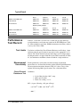
Performance
Test Record
Table 2-1, Performance Test Record, is a form you can copy and use to
record performance verification test results for the FET Multiplexer. Table
2-1 shows multiplexer test limits, DMM measurement uncertainty, and test
accuracy ratio values (TAR).
Test Limits
Test limits are defined for Closed Channel Resistance and Leakage (input
isolation) using the specifications in Appendix A of the appropriate User’s
Manual. The closed channel resistance and leakage tests are single-ended,
meaning that there is an upper limit OR a lower limit but not both. In Table
2-1, the minimum or maximum column is blank for a single ended test.
Measurement
Uncertainty
For the performance verification tests in this manual, measurement
uncertainties are calculated based on the Agilent 3458A Digital Multimeter.
The measurement uncertainty shown in Table 2-1 is the accuracy of the
Agilent 3458A using 90-day specifications. The calculations follow.
Closed Channel
Resistance Test
Conditions:
• 2-wire Ohms function, 10 kΩ range
• 90 day specifications
• Worst case reading = 3.1 kΩ
MU = (8 ppm of Reading + 0.5 ppm of Range)
= ((8 X 10-6 * 3100) + (0.5 X 10-6 * 104))
= 0.03 Ω
2-22 Verification Tests
Leakage Test
Conditions:
•
•
•
•
•
DC Volts function, 100 mV range
90 day specifications
Worst case reading = 0.01 V
Resistor value: 99 kΩ < R < 101 kΩ
Power supply value: 9.9 Vdc < PS < 10.1 Vdc
3458 Uncert = (5 ppm of Reading + 10 ppm of Range)
=((5 X 10-6 * 0.01) + (10 X 10-6 * 0.1))
= 1.05 X 10⁻⁶ Volts
Resistor Uncert =
( 10
10
8
+ RMAX
∗ RMAX
) − ( 10
8
10
+ RMIN
∗ RMIN
)
= ( 1.008 X 10⁻² ) − ( 9.89 X 10⁻³ )
=1.99 X 10⁻⁴ Volts
Power Supply Uncert =
PS
( 1.001
X 10
MAX
8
∗ 105
) − ( 1.001PS X 10
MIN
8
∗ 105
)
= ( 1.008 X 10⁻² ) − ( 9.89 X 10⁻³ )
= 1.99 X 10⁻⁴ Volts
MU = 3458A Uncert + Resistor Uncert + Power Supply Uncert
= ( 1.05 X 10⁻⁶) + ( 1.99 X 10⁻⁴) + ( 1.99 X 10⁻⁴)
= 3.99 X 10⁻⁴ Volts
Test Accuracy
Ratio (TAR)
Test Accuracy Ratios (TAR) are not defined for single-ended
measurements, so all closed channel resistance and leakage current tests
show NA (Not Applicable) in the TAR column.
Verification Tests 2-23
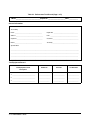
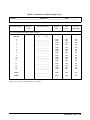
Table 2-1. Performance Test Record (Page 1 of 2)
Model ______________________________Report No. _____________________Date ___________
General Information
Test Facility:
Name _____________________________________
Report No. _________________________________
Address _____________________________________
Date _____________________________________
City/State ___________________________________
Customer ___________________________________
Phone _____________________________________
Tested by __________________________________
Special Notes:
_____________________________________________________________________________________________
_____________________________________________________________________________________________
____________________________________________________________________________________________
____________________________________________________________________________________________
Test Equipment Record
Test Equipment Used:
Description
Model No.
Trace No.
Cal Due Date
1. _______________________________
_______________
_______________
_______________
2. _______________________________
_______________
_______________
_______________
3. _______________________________
______________
______________
______________
2-24 Verification Tests
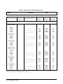
Table 2-1. Performance Test Record (Page 2 of 3)
Model ______________________________Report No. _____________________Date ___________
Test No/Description
Minimum*
Value
Measured Value (V)
Maximum
Value
Meas
Uncert
Test Acc
Ratio (TAR)
2-1. Closed Channel Resistance (Values in Ohms)
Channels
HI
LO
0
1
2
3
________
________
________
________
________
________
________
________
3100
3100
3100
3100
3E-2
3E-2
3E-2
3E-2
NA
NA
NA
NA
4
5
6
7
________
________
________
________
________
________
________
________
3100
3100
3100
3100
3E-2
3E-2
3E-2
3E-2
NA
NA
NA
NA
8
9
10
11
________
________
________
________
________
________
________
________
3100
3100
3100
3100
3E-2
3E-2
3E-2
3E-2
NA
NA
NA
NA
12
13
14
15
________
________
________
________
________
________
________
________
3100
3100
3100
3100
3E-2
3E-2
3E-2
3E-2
NA
NA
NA
NA
Tree A
________ ________
3100
3E-2
NA
Tree B
________ ________
3100
3E-2
NA
*Single-sided specification - Minimum value does not apply
Verification Tests 2-25
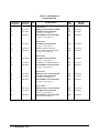
Table 2-1. Performance Test Record (Page 3 of 3)
Model ______________________________Report No. _____________________Date ___________
Test No/Description
Minimum
Value *
Measured Value (V)
Maximum
Value
Meas
Uncert
Test Acc
Ratio (TAR)
HI to LO
Direct
Channels
Tree A
Tree B
___________________
___________________
___________________
___________________
0.01
0.01
0.01
0.01
3.99E-4
3.99E-4
3.99E-4
3.99E-4
NA
NA
NA
NA
HI to Chassis
Direct
Channels
Tree A
Tree B
___________________
___________________
___________________
___________________
0.01
0.01
0.01
0.01
3.99E-4
3.99E-4
3.99E-4
3.99E-4
NA
NA
NA
NA
LO to Chassis
Direct
Channels
Tree A
Tree B
___________________
___________________
___________________
___________________
0.01
0.01
0.01
0.01
3.99E-4
3.99E-4
3.99E-4
3.99E-4
NA
NA
NA
NA
2-2: Leakage (Values in Volts)
Positive polarity
Negative polarity
*Single-sided specification - Minimum value does not apply
2-26 Verification Tests
Chapter 3
Replaceable Parts
Introduction
This chapter contains information to order replaceable parts for the Agilent
E1351A, E1352A, E1353A, E1357A, and E1358A FET Multiplexers. Table
3-1 lists replaceable parts for major assemblies of the FET Multiplexers.
Table 3-2 lists selected mechanical parts for the Component assembly.
Table 3-3 lists parts for the terminal case. Table 3-4 shows reference
designators for the parts listed in Tables 3-1 through 3-3. Table 3-5 shows
the manufacturer code list for these parts.
To order a part listed in Table 3-1 through through 3-3, specify the Agilent
Technologies part number and the quantity required. Send the order to your
nearest Agilent Technologies Sales and Support Office.
Replaceable
Parts Lists
Table 3-1 lists the part numbers of the major assemblies of the FET
Multiplexers. Table 3-2 lists mechanical replaceable parts for the
Component Assembly (common to all FET Multiplexers). Table 3-3 lists
replaceable parts for the Terminal Case Assembly (Common to all FET
Multiplexers)
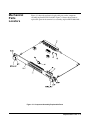
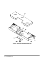
Figure 3-1 shows the Component Assembly and Figure 3-2 shows the
Terminal Case Assembly.
A CLIP package, including component level replaceable parts lists, is
available for the FET Multiplexers (order Agilent part number
E1351-90033).
Exchange
Assembly
The component assembly may be replaced on an exchange basis. Exchange
assemblies are available only on a trade-in basis. Defective assemblies must
be returned for credit. Order assemblies for spare parts stock by the new
assembly part number given in Table 3-1. Terminal blocks and case
assemblies are not available for exchange. The component assembly
exchange part number is: E1351-69201
Replaceable Parts 3-1
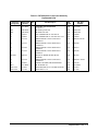
Table 3-1. FET Multiplexer
Replaceable Parts
Reference
Designator
Agilent Part
Number
Qty
Part Description
Mfr.
Code
Mfr. Part
Number
Agilent E1351A
A1
E1351-66510
1
TERMINAL BLOCK FOR MULTIPLEXER
28480
E1351-66510
A2
E1351-66201
1
16-CHANNEL FET MULTIPLEXER
(See Figure 3-1 and Table 3-2)
28480
E1351-66201
A3
E1300-84401
1
CASE ASSEMBLY FOR MULTIPLEXER
(See Figure 3-2 and Table 3-3)
28480
E1300-84401
A1
E1351-66201
1
28480
E1351-66201
A2
E1352-66510
1
TERMINAL CARD 48 C FET MUX
28480
E1352-66510
A4
E1300-84401
1
CASE ASSEMBLY FOR MULTIPLEXER
(See Figure 3-2 and Table 3-3)
28480
E1300-84401
A1
E1351-66201
1
16-CHANNEL FET MULTIPLEXER
(See Figure 3-1 and Table 3-2)
28480
E1351-66201
A2
E1353-66510
1
PC BOARD ASSY; TERMINAL MODULE
28480
E1353-66510
A4
E1300-84401
1
CASE ASSEMBLY FOR MULTIPLEXER
(See Figure 3-2 and Table 3-3)
28480
E1300-84401
A1
E1355-66510
1
TERMINAL RELAY - 120 OHM FOR MUX
28480
E1355-66510
A2
E1351-66201
1
16-CHANNEL FET MULTIPLEXER
(See Figure 3-1 and Table 3-2)
28480
E1351-66201
A4
E1300-84401
1
CASE ASSEMBLY FOR MULTIPLEXER
(See Figure 3-2 and Table 3-3)
28480
E1300-84401
A1
E1356-66510
1
TERMINAL RELAY - 350 OHM FOR MUX
28480
E1356-66510
A2
E1351-66201
1
16-CHANNEL FET MULTIPLEXER
(See Figure 3-1 and Table 3-2)
28480
E1351-66201
A4
E1300-84401
1
CASE ASSEMBLY FOR MULTIPLEXER
(See Figure 3-2 and Table 3-3)
28480
E1300-84401
Agilent E1352A
16-CHANNEL FET MULTIPLEXER
(See Figure 3-1 and Table 3-2)
Agilent E1353A
Agilent E1357A
Agilent E1358A
3-2 Replaceable Parts
Table 3-2. FET Multiplexer Component Assembly
Replaceable Parts
Reference
Designator
Agilent Part
Number
Qty
Part Description
Mfr.
Code
Mfr. Part
Number
E1351-66201
1
16-CHANNEL FET MULTIPLEXER
(See figure 3-1)
28480
E1351-66201
LBL1
E1300-84308
1
LBL LOGO Agilent B SIZE
28480
E1300-84308
LBL2
E1300-84309
1
LBL LOGO VXI B SIZE
28480
E1300-84309
F1
2110-0712
1
FUSE-SUBMINIATURE 4A 125V NTD AX
75915
R251004T1
F2
2110-0665
1
FUSE-SUBMINIATURE 1A 125V NTD AX UL CSA
75915
R251001T1
J1
1252-1596
2
CONNECTOR-POST TYPE 2.54-PIN-SPCG
96-CONTACT
06776
DIN-96CPC-SRI-TR
J2
1252-3712
1
CONNECTOR-POST TYPE .100-PIN-SPCG
12-CONTACT
18873
68668-004
J3
1252-3868
1
CONNECTOR-POST TYPE .100-PIN-SPCG
6-CONTACT
18873
68668-071
J4
1251-8735
1
CONNECTOR-POST TYPE .100-PIN-SPCG
8-CONTACT
18873
67997-608
MP1-MP2
1400-1546
2
BRACKET PC BOARD HOLDER; BLACK;
EXTRUDED
28480
1400-1546
P1
1252-1596
CONNECTOR-POST TYPE 2.54-PIN-SPCG
96-CONTACT
06776
DIN-96CPC- SRI-TR
P4
1258-0247
1
JUMPER-4 POSITIONS HOUSING MATERIAL
18873
69146-204
PNL1
E1351-00202
1
PNL-RR MATRIX SW
28480
E1351-00202
SCR1-SCR2
0515-0444
2
SCREW-MACHINE M2.5 X 0.45 8MM-LG PAN-HD
28480
0515-0444
SCR3-SCR4
0515-1968
2
SCREW PHM 2.5 X 11
28480
0515-1968
Replaceable Parts 3-3
Table 3-3. Terminal Case
Replaceable Parts
Reference
Designator
Agilent Part
Number
Qty
Part Description
Mfr.
Code
Mfr. Part
Number
E1300-84401
1
CASE ASSEMBLY FOR MULTIPLEXER
(See Figure 3-2)
28480
E1300-84401
CS1
03852-01201
1
CLAMP
28480
03852-01201
CS2
03852-86701
1
PAD - CLAMP
28480
03852-86701
CS3
0515-2109
1
SCREW - MACHINE 10-24 .625-IN-LG PAN-HD-SLT 28480
0515-2109
CS4
1390-0846
2
FASTENER-CAPTIVE SCREW M2.5 X 1.45
THREAD
1390-0846
CS5
E1300-01202
1
CLAMP-STRAIN RELEIF
28480
E1300-01202
CS6
E1300-44101
1
COVER-TOP, TERMINAL HOUSING, MOLDED
28480
E1300-44101
CS7
E1300-44102
1
COVER-BOTTOM, TERMINAL HOUSING
28480
E1300-44102
28480
Table 3-4. FET Multiplexers Reference Designators
FET Multiplexers Reference Designators
A ................................................... assembly
LBL ....................................................... label
F ............................................................fuse
J.......................... electrical connector (jack)
JM......................................................jumper
MP...................................... mechanical part
P......................... electrical connector (plug)
PNL ..................................................... panel
SCR.................................................... screw
SW .....................................................switch
Table 3-5. FET Multiplexer Code List of Manufacturers
Mfr.
Code
Manufacturer’s
Name
Manufacturer’s
Address
Zip
Code
06776
ROBINSON NUGENT INC
NEW ALBANY NY US
47150
18873
DUPONT E I DE NEMOURS & CO
WILMINGTON DE US
19801
26742
METHODE ELECTRONICS INC
CHICAGO IL US
60656
28480
AGILENT TECHNOLOGIES CORPORATE
PALO ALTO CA US
94304
60016
75915
LITTELFUSE INC
DES PLAINES IL US
76381
3M CO
ST PAUL MN US
55144
81073
GRAYHILL INC
LA GRANGE IL US
60525
3-4 Replaceable Parts
Mechanical
Parts
Locators
Figure 3-1 shows the mechanical replaceable parts on the component
assembly (Agilent PN E1351-66201). Figure 3-2 shows the mechanical
replaceable parts for the terminal case assembly (Agilent PN E1300-84401).
Figure 3-1. Component Assembly Replaceable Parts
Replaceable Parts 3-5
Figure 3-2. Terminal Case Assembly Replaceable Parts
3-6 Replaceable Parts
Chapter 4
Service
Introduction
This chapter contains service information for the Agilent E1351A, E1352A,
E1353A, E1357A, and E1358A FET Multiplexers. Also included are
trouble shooting, repair, and maintenance guidelines.
WARNING
Do not perform any of the service procedures shown unless
you are a qualified, service-trained technician and have read the
WARNINGS and CAUTIONS in Chapter 1.
Equipment
Required
Service Aids
FET Multiplexer
Description
Equipment required for module troubleshooting and repair is listed in
Table 1-1, Recommended Test Equipment. Any equipment that satisfies the
requirements given in the table may be substituted. To avoid damage to the
screw head slots, use a T8 Torx driver to remove the front panel handles.
See Chapter 3 — Replaceable Parts for descriptions and locations of
Agilent E1351A, E1352A, E1353A, E1357A, and E1358A replaceable
parts. Service notes, manual updates, and service literature for the FET
Multiplexers may be available through Agilent Technologies. For
information, contact your nearest Agilent Technologies Sales and Service
Office.
The Agilent E1351A, E1352A, E1353A, E1357A, and E1358A all use a
common component assembly. The component assembly contains all the
FET switches and their associated protection circuitry. Each terminal block
configures the component assembly to the appropriate type of switch.
Figures 4-1 through 4-4 show a simplified switching diagram for each FET
Multiplexer.
The terminal card contains the model identification code and the installation
of the terminal card before applying mainframe power ensures that the type
of switch is correctly identified. Optionally, the model identification can be
set on the component assembly to allow it to be correctly identified without
a terminal card installed. The component module also contains jumpers that
place the internal +4.6 V strain gage excitation voltage on the terminal block
Service 4-1
Figure 4-1. Agilent E1351A Simplified Switch Diagram
4-2 Service
Figure 4-2. Agilent E1352A Simplified Switch Diagram
Service 4-3
Figure 4-3. Agilent E1353A Simplified Switch Diagram
4-4 Service
Figure 4-4. Agilent E1357A/58A Simplified Switch Diagram
Service 4-5
for use with the Agilent E1357A and Agilent E1358A Strain Gage FET
Multiplexers.
Repair Strategy
Agilent Technologies recommends replacement of the entire assembly in the
event of a failure. Procedures in this chapter describe troubleshooting
techniques. A CLIP package, including component level replaceable parts
lists, is available for the FET Multiplexers (order Agilent part number
E1351-90033). The component assembly is available as an exchange
asembly as described in Chapter 3 — Replaceable Parts. Be sure to perform
the tests and checks in Table 4-2 before exchanging an assembly.
Troubleshooting
Techniques
To troubleshoot a FET Multiplexer problem you must first identify the
problem and then isolate the cause of the problem to a replaceable assembly.
See Chapter 3 — Replaceable Parts for descriptions and locations of
Agilent E1351A, E1352A, E1353A, E1357A, and E1358A replaceable parts.
Identifying the
Problem
Table 4-1 lists some common problems for the Agilent E1351A, E1352A,
E1353A, E1357A, and E1358A FET Multiplexers, along with symptoms
and possible solutions. If the problem cannot be identified using these steps,
replace the assembly.
Table 4-1. FET Multiplexer Typical Problems
Symptom
4-6 Service
Recommended Action
Non-zero error code in
response to SYST:ERR?
See Appendix A of the appropriate
FET Multiplexer User’s Manual.
Module not responding to
commands.
See "Making Visual Checks" in this
chapter
Module fails Closed
Channel Resistance Test
(Test 2-1) or Leakage
Test (Test 2-2)
See "Testing the Module" in this
chapter
Making Visual
Checks
Visual checks for the FET Multiplexers include the following. See
Table 4-2 for typical checks.
• Check switches/jumpers
• Check for heat damage
• Checking connector contacts
NOTE
See the appropriate FET Multiplexer User’s Manual for information on
logical address and IRQ settings. If there are no apparent problems
following the visual checks, run the Performance Verification Tests in
Chapter 2 to see if the module is defective.
Table 4-2. FET Multiplexer Visual Tests/Checks
Test/Check
Reference
Designator
Check
Action/Notes
Heat Damage
-------------
Discolored PC boards
Damaged insulation
Evidence of arcing
If there is damage, do not
operate the module until you
have corrected the problem.
Switch/Jumper
Settings
SP2
SP1
SP3
J4
JM1
IRQ Level setting
Logical address setting
Card ID
Strain Excitation
Remote Ground Sense
Factory set at 1
Factory set at 112
Factory set 00
Factory set to OFF
Factory Installed
Component
Assembly
F1, F2
J1, J2, J3
P1
Fuse continuity
Dirty or bent connector pins
Dirty or bent connector pins
Check fuses with ohmmeter
Straighten/clean pins
Straighten/clean pins
Testing the Module
You can use the tests and checks in Chapter 2 — Verification Tests to
identify a problem with the assembly. See Chapter 3 — Replaceable Parts
for locations of mechanical parts.
Service 4-7
Repair and
Maintenance
Guidelines
ESD Precautions
This section provides guidelines for repairing and maintaining the FET
Multiplexer including:
• ESD precautions
• Soldering printed circuit boards
• Post-repair safety checks
Electrostatic discharge (ESD) may damage static sensitive devices in the
module. This damage can range from slight parameter degradation to
catastrophic failure. When handling the module observe the following
guidelines:
• Always use a static-free work station with a pad of conductive rubber or
similar material when handling module components.
• If a device requires soldering, be sure the assembly is placed on a pad of
conductive material. Also, be sure that you, the pad, and the soldering
iron tip are grounded to the assembly.
Soldering Printed
Circuit Boards
The etched circuit board of this module has plated-through holes that
provide a solder path to both sides of the insulating material. Soldering can
be done from either side of the board with equally good results. When
soldering to any circuit board, keep in mind the following guidelines:
• Avoid unnecessary component unsoldering and soldering. Excessive
replacement can result in damage to the circuit board, adjacent
components, or both.
• Do not use a high power soldering iron on etched circuit boards, as
excessive heat may lift a conductor or damage the board.
• Use a suction device or wooden toothpick to remove solder from
component mounting holes. When using a suction device, be sure that the
equipment is properly grounded.
Post-Repair Safety
Checks
4-8 Service
After making repairs to the module, inspect the module for any signs of
abnormal internally generated heat, such as discolored printed circuit boards
or components, damaged insulation, or evidence of arcing. Determine and
correct the cause of the condition. Then perform Test 2-1 as described in
Chapter 2 — Verification Tests to verify that the module is functional.
Chapter A
Verification Tests - C Programs
Functional
Verification
Test
This program is designed to do the Functional Verification Test found in
Chapter 2 - Verification Tests.
Example: Self Test
NOTE
The Functional Verification Test for the Agilent E1351A, E1352A,
E1353A, E1357A, and E1358A FET Multiplexers consists of sending the
*IDN? command and checking the response. This test can be used to verify
that the FET Multiplexer is connected properly and is responding to a basic
command.
This program assumes a primary address of 09 and a secondary address of
14. If your FET Multiplexer address does not match this, you must either
change the FET Multiplexer address setting or change the program line
#define ADDR "hpib7,9,14" to match your FET Multiplexers address
setting.
#include <stdio.h>
#include <sicl.h>
#define ADDR "hpib7,9,14"
/* Address of device */
void main (void)
{
INST id;
char a[256] = {0};
/* Define id as an instrument */
/* Result variable */
ionerror (I_ERROR_EXIT);
id = iopen (ADDR);
/* Open instrument session */
iprintf(id, "*IDN?\n");
iscanf (id, "%t", a);
printf("\n %s", a);
getchar();
iclose (id);
}
/* Send *IDN? command */
/* Get response */
/* Print result */
/* Pause */
/* Close instrument session */
Example C Programs A-1
Performance
Verification
Tests
These programs are designed to do the Performance Verification Tests
found in Chapter 2 - Verification Tests.
NOTE
These programs assume a primary address of 09 and a secondary address
of 14. If your FET Multiplexer address does not match this, you must either
change the FET Multiplexer address setting or change the program lines
#define ADDR "hpib7,9,14" to match your FET Multiplexers address
setting.
Example: Closed
Channel
Resistance Test
This example performs a closed channel resistance test of all measurement
paths. If a FET on resistance is >3.1 kΩ , the program prints a message
indicating which channel has failed. Before the closed channel
measurement, the program checks for stuck channels. If a stuck channel is
found, the program prints a message and halts.
/* Closed-channel Resistance Test
E1351A */
#include <stdio.h>
#include <sicl.h>
#define ADDR "hpib7,9,14"
#define DMM "hpib7,22"
/* Address of device */
void main (void)
{
INST id, dm;
int i, j;
double result[2][15], tree[2][2], value;
char cr[256];
char *path;
/* Define id and dm as an instrument */
#if defined(__BORLANDC__) && !defined(__WIN32__)
_InitEasyWin();
#endif
ionerror(I_ERROR_EXIT);
dm = iopen (DMM);
id = iopen(ADDR);
/* Open instrument session */
printf ("\n\n\nInstall Component Assembly and Test Fixture");
printf ("\n\n 1. Turn Mainframe AND 3458a DMM power OFF.");
printf ("\n 2. Connect GPIB Cable between mainframe and DMM.");
printf ("\n 3. Install Agilent E1351A Component Assembly into Mainframe.");
printf ("\n 4. Attach Test Fixture to Component Assembly.");
printf ("\n 5. Turn Mainframe and DMM power ON");
printf ("\n 6. Press ENTER when ready to begin testing.");
getchar ();
A-2 Example C Programs
/*...........................Measure Closed Channel Resistance...........*/
iprintf (id, "*RST\n");
iprintf (dm, "PRESET NORM;TRIG HOLD\n");
iprintf (dm, "END ALWAYS\n");
iprintf (dm, "FUNC OHM\n");
for (i = 0;i <= 1; i++)
{
if (i == 0) path = "HI";
else
path = "LO";
printf ("\n\nChannel %s to Direct %s Measurements", path, path);
printf ("\n\n 1. Connect DMM Input HI lead to Channel %s", path);
printf ("\n 2. Connect DMM Input LO lead to Direct %s", path);
printf ("\n 3. Press ENTER when connections are complete");
getchar ();
/*-------Check for stuck channels------*/
iprintf (id, "*RST\n");
iprintf (dm, "TRIG SGL\n");
iscanf (dm, "%lf", &value);
iscanf (dm, "%t", cr);
if (value < 10000)
{
printf ("\n\n***** Measurement indicates a stuck channel *****");
printf ("\n***** Correct the problem before proceeding *****");
goto EXIT;
}
for (j = 0;j <= 15; j++)
{
if (j < 10) iprintf (id, "CLOS (@10%u)\n", j);
else
iprintf (id, "CLOS (@1%u)\n", j);
iprintf (dm, "TRIG SGL\n");
iscanf (dm, "%lf", &result[i][j]);
iscanf (dm, "%t", cr);
printf ("\nchannel %u resistace = %6.4lf", j, result[i][j]);
if (j < 10) iprintf (id, "OPEN (@10%u)\n", j);
else
iprintf (id, "OPEN (@1%u)\n", j);
if (result[i][j] > 3100) printf ("\n*** Resistance for Channel %u is 3.1 kOhms ***
%6.4lf Ohms", j, result[i][j]);
}
if (i == 0)
{
printf ("\n\nMeasurements complete for channel HI.");
printf ("\nPress ENTER for channel LO measurements");
getchar ();
}
else
{
printf ("\n\nMeasurements complete for channel LO.");
}
}
Example C Programs A-3
printf ("\n\nMeasurements complete for Channel HI and LO");
printf ("\nPress ENTER for Tree Switch measurements");
getchar ();
/*...........................Tree Switch Measurements..................................*/
iprintf (dm, "PRESET NORM;TRIG HOLD\n");
iprintf (dm, "END ALWAYS\n");
iprintf (dm, "FUNC OHM\n");
for (i = 0;i <= 1; i++)
{
if (i == 0)
{
path = "HI";
printf ("\n\nTree HI to Direct HI Measurements");
printf ("\n\n 1. Connect DMM Input HI leads to Tree HI");
printf ("\n 2. Connect DMM Input LO leads to Direct HI");
}
else
{
path = "LO";
printf ("\n\nTree LO to Direct LO Measurements");
printf ("\n\n 1. Connect DMM Input HI leads to Tree LO");
printf ("\n 2. Connect DMM Input LO leads to Direct LO");
}
printf ("\n 3. Press ENTER when connections are complete.");
getchar ();
iprintf (id, "*RST\n");
/*-------Check for stuck channels------*/
iprintf (dm, "TRIG SGL\n");
iscanf (dm, "%lf", &value);
iscanf (dm, "%t", cr);
if (value < 10000)
{
printf ("\n\n***** Measurement indicates a stuck channel *****");
printf ("\n***** Correct the problem before proceeding *****");
goto EXIT;
}
for (j = 0; j <= 1; j++)
{
iprintf (id, "SCAN:PORT ABUS\n");
if (j == 0) iprintf (id, "CLOS (@100)\n");
else
iprintf (id, "CLOS (@115)\n");
iprintf (dm, "TRIG SGL\n");
iscanf (dm, "%lf", &tree[i][j]);
iscanf (dm, "%t", cr);
if (j == 0) iprintf (id, "OPEN (@100)\n");
else
iprintf (id, "OPEN (@115)\n");
A-4 Example C Programs
}
if (tree[i][j] > 3100)
{
if (j == 0) printf ("\n*** Resistance for A Tree Switch is 3.1 kOhms");
else
printf ("\n*** Resistance for B Tree Switch is 3.1 kOhms");
}
if (i == 0)
{
printf ("\n\nMeasurements complete for Tree Switch HI");
printf ("\nPress ENTER forTree Switch LO measurements");
getchar();
}
else
{
printf ("\n\nMeasurements complete for Tree Switch LO");
}
}
printf ("\n\nClosed channel resistance measurements complete.");
printf ("\nPress ENTER to display measurement results.");
getchar ();
/*...........................Display Measurement Results................................*/
printf ("\n\n---------------------------------------------");
printf ("\n\nClosed Channel Resistance measurement Results\n");
for (j = 0;j <= 15; j++)
{
printf ("\n Channel %u HI = %6.4lf Ohms LO = %6.4lf Ohms", j+100,
result[0][j], result[1][j]);
}
printf ("\n\n Tree A
tree[1][0]);
printf ("\n Tree B
HI = %6.4lf Ohms LO = %6.4lf Ohms", tree[0][0],
HI = %6.4lf Ohms LO = %6.4lf Ohms", tree[0][1], tree[1][1]);
EXIT:
iclose (id);iclose (dm);
}
/* Close instrument session */
Example C Programs A-5
Example: Leakage
Current Test
This example performs a leakage test from HI to LO, HI to Chassis, and LO
to Chassis. If the leakage is too high (caused by a failure of the input
impedance), the test prints a message indicating which leakage path has
failed and halts.
/* Leakage Current Test
E1351A */
#include <stdio.h>
#include <sicl.h>
#define ADDR "hpib7,9,14"
#define DMM "hpib7,22"
void main (void)
{
INST id, dm;
int i;
double result[6][4], value;
char cr[256];
char *path;
/* Address of device */
/* Define id and dm as an instrument */
#if defined(__BORLANDC__) && !defined(__WIN32__)
_InitEasyWin();
#endif
ionerror(I_ERROR_EXIT);
dm = iopen (DMM);
id = iopen(ADDR);
itimeout (dm, 10000);
itimeout (id, 10000);
printf ("\n\n\nInstall Component Assembly and Test Fixture");
printf ("\n\n 1. Turn Mainframe AND 3458a DMM power OFF.");
printf ("\n 2. Connect GPIB Cable between mainframe and DMM.");
printf ("\n 3. Install Agilent E1351A Component Assembly into Mainframe.");
printf ("\n 4. Attach Test Fixture to Component Assembly.");
printf ("\n 5. Turn Mainframe and DMM power ON");
printf ("\n 6. Press ENTER when ready to begin testing.");
getchar ();
/*...........................Measure Leakage........................................*/
iprintf (dm, "PRESET NORM;TRIG HOLD\n");
iprintf (dm, "END ALWAYS\n");
iprintf (dm, "FUNC DCV\n");
for (i = 0;i <= 5; i++)
{
iprintf (id, "*RST\n");
printf ("\n\n1. Connect 100 kOhm resistor from DMM Input HI to DMM Input LO");
A-6 Example C Programs
if (i == 0)
{
printf ("\n2. Connect DMM input HI leads to Power Supply HI");
printf ("\n3. Connect DMM input LO leads to Direct HI");
printf ("\n4. Connect Power Supply LO to Direct LO");
}
if (i == 1)
{
printf ("\n2. Connect DMM input HI leads to Direct HI");
printf ("\n3. Connect DMM input LO leads to Power Supply LO");
printf ("\n4. Connect Power Supply HI to Direct LO");
}
if (i == 2)
{
printf ("\n2. Connect DMM input HI leads to Power Supply HI");
printf ("\n3. Connect DMM input LO leads to Direct LO");
printf ("\n4. Connect Power Supply LO to Chassis");
}
if (i == 3)
{
printf ("\n2. Connect DMM input HI leads to Direct HI");
printf ("\n3. Connect DMM input LO leads to Power Supply LO");
printf ("\n4. Connect Power Supply HI to Chassis");
}
if (i == 4)
{
printf ("\n2. Connect DMM input HI leads to Power Supply HI");
printf ("\n3. Connect DMM input LO leads to Direct LO");
printf ("\n4. Connect Power Supply LO to Chassis");
}
if (i == 5)
{
printf ("\n2. Connect DMM input HI leads to Direct LO");
printf ("\n3. Connect DMM input LO leads to Power Supply LO");
printf ("\n4. Connect Power Supply HI to Chassis");
}
printf ("\n5. Turn ON power supply and set output for +10 Vdc");
printf ("\n6. Press ENTER when connections are complete");
getchar ();
printf (".");
iprintf (dm, "TRIG SGL\n");
iscanf (dm, "%lf", &result[i][0]);
iscanf (dm, "%t", cr);
if (result[i][0] > .01)
printf ("\n\n***** Direct path leakage out of tolerance %6.4lf Volts *****",
result[i][0]);
/*...........................Channel Check.................................................*/
printf (".");
iprintf (id, "CLOS (@100)\n");
iprintf (dm, "TRIG SGL\n");
iscanf (dm, "%lf", &result[i][1]);
iscanf (dm, "%t", cr);
Example C Programs A-7
if (result[i][1] > .01)
printf ("\n\n***** Channel path leakage out of tolerance %6.4lf Volts *****",
result[i][1]);
/*...........................Tree Check....................................................*/
printf (".");
iprintf (id, "SCAN:PORT ABUS\n");
iprintf (id, "CLOS (@100)\n");
iprintf (dm, "TRIG SGL\n");
iscanf (dm, "%lf", &result[i][2]);
iscanf (dm, "%t", cr);
if (result[i][2] > .01)
printf ("\n\n***** Tree A path leakage out of tolerance %6.4lf Volts *****",
result[i][2]);
printf (".");
iprintf (id, "OPEN (@100)\n");
iprintf (id, "CLOS (@115)\n");
iprintf (dm, "TRIG SGL\n");
iscanf (dm, "%lf", &result[i][3]);
iscanf (dm, "%t", cr);
if (result[i][3] > .01)
printf ("\n\n***** Tree B path leakage out of tolerance %6.4lf Volts *****",
result[i][3]);
printf (".");
if (i < 5)
{
printf ("\n\nTest %u complete", i+1);
printf ("\nTurn power supply OFF");
printf ("\nPress ENTER for test %u", i+2);
getchar ();
}
}
printf ("\n\nLeakage tests complete.");
printf ("\nPress ENTER to display measurement results.");
getchar ();
/*...........................Display Measurement Results................................*/
printf ("\n\n-------------------------------------------------------------");
printf ("\n
Positive Polarity Leakage
\n");
printf ("\n-------------------------------------------------------------");
printf ("\n
Direct
Channels Tree A
Tree B\n");
printf ("\nHI to LO
%6.4lf Vdc %6.4lf Vdc %6.4lf Vdc %6.4lf Vdc", result[0][0],
result[0][1], result[0][2], result[0][3]);
printf ("\nHI to Chassis %6.4lf Vdc %6.4lf Vdc %6.4lf Vdc %6.4lf Vdc",
result[1][0], result[1][1], result[1][2], result[1][3]);
printf ("\nLO to Chassis %6.4lf Vdc %6.4lf Vdc %6.4lf Vdc %6.4lf Vdc",
result[2][0], result[2][1], result[2][2], result[2][3]);
A-8 Example C Programs
printf ("\n\n-------------------------------------------------------------");
printf ("\n
Negative Polarity Leakage
\n");
printf ("\n-------------------------------------------------------------");
printf ("\n
Direct
Channels Tree A
Tree B\n");
printf ("\nHI to LO
%6.4lf Vdc %6.4lf Vdc %6.4lf Vdc %6.4lf Vdc", result[3][0],
result[3][1], result[3][2], result[3][3]);
printf ("\nHI to Chassis %6.4lf Vdc %6.4lf Vdc %6.4lf Vdc %6.4lf Vdc",
result[4][0], result[4][1], result[4][2], result[4][3]);
printf ("\nLO to Chassis %6.4lf Vdc %6.4lf Vdc %6.4lf Vdc %6.4lf Vdc",
result[5][0], result[5][1], result[5][2], result[5][3]);
}
iclose (id);iclose (dm);
/* Close instrument session */
Example C Programs A-9
A-10 Example C Programs