1
Ramsey Electronics Model No.
FM-100
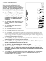
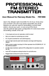
Now here’s the ultimate radio transmitter for all of you home
brew DJs out there! This all-in-one stereo transmitter has all
the features you will ever need for transmitting for a school
radio station, around your yard, or even around the block.
With an optional high power module for out of the US
transmitting, this is definitely a professional unit!
•
2 Line inputs and one mic input-plus a built in mixer!
•
PLL Crystal controlled for rock solid frequency
•
Left and right channel peak hold indicators and large LED
frequency display
•
•
Built in power supply, just plug it in!
25mW output standard, optional 1W module for foreign
country operation
•
Auto AGC microphone muting function for cool talk overs
•
Rugged steel enclosure for years of use
FM-100 Page 1
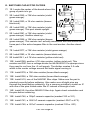
PARTIAL LIST OF AVAILABLE KITS
RAMSEY TRANSMITTER KITS
• FM100 Professional FM Stereo Transmitter
• FM25 Synthesized Stereo FM
Transmitter
• MR6 Model Rocket Tracking
Transmitter
• TV6 Television Transmitter
RAMSEY RECEIVER KITS
• FR1 FM Broadcast Receiver
• AR1 Aircraft Band Receiver
• SR2 Shortwave Receiver
• SC1 Shortwave Converter
RAMSEY HOBBY KITS
• SG7 Personal Speed Radar
• SS70A Speech Scrambler
• BS1 “Bullshooter” Digital Voice
Storage Unit
• AVS10 Automatic Sequential Video Switcher
• WCT20 Cable Wizard Cable Tracer
• LC1 Inductance-Capacitance Meter
RAMSEY AMATEUR RADIO KITS
• FX 146 VHF Transceiver
• HR Series HF All Mode Receivers
• QRP Series HF CW Transmitters
• CW700 Micro Memory CW Keyer
• CPO3 Code Practice Oscillator
• QRP Power Amplifiers
RAMSEY MINI-KITS
Many other kits are available for hobby, school, Scouts and just plain FUN.
New kits are always under development. Write or call for our free Ramsey
catalog.
FM-100 PROFESSIONAL STEREO TRANSMITTER INSTRUCTION MANUAL
Ramsey Electronics publication No. MFM-100 Revision 1.1a
First printing: April. 1996 MRW
COPYRIGHT 1996 by Ramsey Electronics, Inc. 793 Canning Parkway, Victor, New York
14564. All rights reserved. No portion of this publication may be copied or duplicated without the
written permission of Ramsey Electronics, Inc. Printed in the United States of America.
FM-100 Page 2
Ramsey Publication No. MFM-100
Price $10.00
KIT ASSEMBLY
AND INSTRUCTION MANUAL FOR
FM-100 PROFESSIONAL
STEREO TRANSMITTER
TABLE OF CONTENTS
Introduction ......................................4
How does it work ..............................5
Parts List ...........................................13
Assembly Index ................................16
Section Layout ..................................17
Display Layout ..................................18
Main Board Layout............................21,22
Schematic Centerfold .......................34,35
Troubleshooting ................................51
Using the FM-100 .............................57
FCC Rules and Information ..............58
RAMSEY ELECTRONICS, INC.
793 Canning Parkway
Victor, New York 14564
Phone (716) 924-4560
Fax (716) 924-4555
FM-100 Page 3
INTRODUCTION TO THE FM-100
First we will begin with a little history of stereo transmitters at Ramsey
Electronics to give you some idea how we arrived at the FM-100 as our latest
stereo transmitter. We have many people call us each day asking questions
about our earlier versions of transmitters such as the FM-25 and the FM-10a.
Most are questions concerning drifting, sound quality, and transmitting
distance. The tunable FM-10a was a great product for a low-cost entry into the
world of micropower transmitters. The FM-25 was the next step up allowing for
a rock solid stable frequency just like professional stations. The latest step was
to create a transmitter that not only has a rock solid frequency, but also all the
features you would find in a commercial station.
Well, in answer to customer research and comment, here is the result of
months of design and years of stereo transmitter experience. The FM-100 has
all of the features needed to run a professional sounding radio station. It
includes extensive audio filtering to prevent high frequency audio interference,
AGC (Automatic Gain Control) with the microphone to prevent overloading
distortion, a frequency display with easy frequency adjustment, 2 line inputs, 1
microphone input, PLL controlled, CD quality transmission, and more. In other
words we pulled all the stops to bring you a top quality product that will satisfy
even the most discriminating user.
Due to demand from our neighbors down south, and wherever it is legal, we
have allowed for a special module to be added to give you a 1 watt RF output.
Simply plug it right in with a minor adjustment, hook up a good antenna and
bingo, you’re on the air over miles.
We are happy to bring you this truly professional product that will give you
many years of fun, reliable use, and enjoyment knowing that you have built it
yourself.
FM-100 Page 4
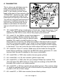
HOW DOES IT WORK?
Here is where we get into a little circuit analysis. If you just want to plug it in and
start broadcasting, you can skip this section and read the FCC regulations
section. Otherwise there is some insight into why and how this FM-100 works.
We will use the schematic located at the center of the manual to analyze the
circuit.
We will begin with the power supply since it is the most common circuit we will
see. When you plug a working unit in, 110 VAC is applied across the primary
winding of the transformer T1. This in turn induces 10 VAC across each
secondary winding. The transformer included in your kit is rated for 500mA per
winding, but we have connected two of them in parallel, allowing us to get 1
Amp at 10 VAC. This current is necessary when the high power module is
added into the kit. The module draws a little more than 500mA when
transmitting, which left no more current for the rest of the kit. The displays draw
10mA per segment, and there are a maximum of 29 of them lit at any time. That
is another 290mA, making for a total of 790mA, not including the rest of the
circuitry. As you can see, this project requires a little power to get on the air, so
a substantial power supply is required for good operation.
The output AC of the transformer is fed to a bridge rectifier, where it is
converted to about 12 VDC, and then smoothed out with C86 and C52, both
3300uF capacitors. These big capacitors were required to reduce ripple in the
power supply to a minimum and therefore reducing 120Hz noise in the audio of
the project.
To get a negative supply for the opamps, we make a negative voltage multiplier
which taps some of the AC from the transformer. C89 passes AC, but not DC,
allowing D7 and D6 to rectify the AC through the capacitor to a negative
voltage. C55 then smoothes out the ripple.
Regulators are then used to completely smooth out any remaining ripple and
other noises present on the power supply. The +12 volts is regulated to +5 volts
by VR3, the +5 volts is then used for digital circuitry and some of the audio
circuitry. The +12 volts is also regulated to +8 volts for most of the audio
circuitry, and the major source of power for the high power module. The -12
volts is regulated to -8 volts for just the audio circuitry.
Now we will get on to the display circuit, and why we designed it this way.
Keeping low noise in mind, we wanted a display that produced as little noise as
possible. We determined that an LED display was our best choice for visibility,
but we couldn’t use display drivers that multiplexed. Multiplexing means that all
of the digits are never on at the same time, but each are turned on in turn at a
high enough rate so that to your eye it looks as if all are lit at the same time.
The switching between the displays produced more noise than we wanted to
have to deal with, so we chose a method where all the displays are constantly
FM-100 Page 5
lit. While this may not be the most efficient method of lighting a display, it is the
least noisy. U3, the MM5451 is just a large serial shift register made for driving
LED segments.
Well, the display wouldn’t do much without a smart device to send it some
meaningful data. In this case we are using a Motorola microcontroller (U4) to do
the job for us. This microcontroller performs most of the operations on the unit
such as checking for button presses, setting the transmitting frequency, muting
audio lines at appropriate times, as well as updating the display.
When the frequency is changed, we access U2, a serially programmed PLL
(Phase Locked Loop). When the frequency needs to be set, the information is
sent serially to U2. This information is a string of binary data, (1's and 0's). In
this way data is sent one bit at a time to U2. The frequency information takes
16 bits, and there are an additional 32 bits sent for the internal control of U2.
You may think that all this would take a long time, but in fact the whole process
from the time you press a frequency control switch until the data is completely
sent is less than 1/100th of a second!
The PLL also takes the 6 MHz crystal frequency and divides it by 60 to obtain a
stable reference frequency of 100KHz. How does it know to divide the crystal
frequency by 60? That is part of the data that is sent from U4 each time a
frequency button is pressed. To set the operating frequency of U6, we simply
send U2 divide by N data to produce the desired frequency from the BA1404’s
VHF oscillator. The oscillator’s frequency is divided by this value N, producing
an output in the 100KHz region. The internal phase detector compares the
highly accurate 100KHz reference with the divide-by-N output and controls the
BA1404 oscillator so that the frequencies match precisely.
Using the example from above, a frequency of 95.3 MHz gives an N of 953, so
the frequency from U3 is divided by 953 and then compared with the reference
frequency of 100 KHz. If the desired frequency is less than the reference
frequency U2 increases the output voltage on pin 13. This increases the
voltage across diode D10, a varactor diode. As the voltage across the varactor
increases, it causes a decrease in capacitance (Increasing reverse bias
essentially increases the distance between the capacitor’s plates by increasing
the depletion region in the diode (C = kA/d). The decrease in capacitance
causes an increase in U6’s RF oscillator (fo = 1/[2π (LC)½]), bringing the FM100’s output frequency back on frequency. If the desired frequency is higher
than the reference, pin 13 is driven low. If the frequency is just right then pin 13
becomes a high impedance, basically disconnecting it from the circuit so it will
cause no change in the voltage on D10. The voltage changes on pin 13 are
filtered by R8, C9, R7, and C11 to provide a steady, noise free tuning voltage
for D10. In this way the output frequency of U6 is "locked" to that desired by the
microcontroller. Meanwhile U4 is polling pin 11, the LD (Lock Detect) output of
U2 to determine if the PLL can achieve a “lock” or not.
FM-100 Page 6
If you are a close observer, you will notice that U4 derives its clock signal from
the PLL. The PLL has a nifty feature of a buffered divided crystal output to drive
external devices such as microcontrollers. This is another part of the 32 bits we
send to the microcontroller other than the divide by N info. When first powered
on, the XCLK line is at the lowest possible divide by C frequency, which is
6MHz / 16 or 375KHz. This runs the microcontroller at a pretty slow rate until
we can send out new information using a C of 4, giving us a clock of 1.5MHz.
This clock frequency is not only used by the microcontroller U4, but also by U9
and U10, the switched capacitive filter circuitry that we will talk more about in a
minute.
U1 is a serially accessed EEPROM, which stores our frequency settings for the
next time we power up the FM-100. This prevents us from having to go through
setting the proper frequency every time we turn off the FM-100. The frequency
data is only set to the EEPROM when the user exits the setup mode, and a
confirming beep from SP1 lets the user know it is written.
U6, the BA1404 FM stereo transmitter IC is what does all the work of creating
your stereo subcarrier, and doctoring your audio signals for transmission. The
BA1404 was originally designed to run from a couple of 1.5 volt batteries, so it
was made to be run at a low voltage. We decided to use a 2.5 volt regulator
(VR1) to give us the proper voltage at the greatest noise immunity from the
power supply. The low level RF output of U6 is then fed to Q2 and surrounding
parts to boost it to a more reasonable level for filtering. Since the RF output of
the BA1404 is not the cleanest, much filtering is required to remove unwanted
transmissions that are outside of the FM band.
The primary filter for the job is the bandpass filter consisting of C84, L5, L4,
C82, L6, and C85. This has a lower cutoff at about 70MHz, and an upper cutoff
at 120MHz. The output of this filter is sent to a class C amplifier consisting of
Q1 and R32. This gives us a higher level output which is adequate for local
broadcast. But before going to the antenna, we low pass filter the output at
110MHz. This gets rid of the unwanted upper harmonics that are very present
in a class C amplifier. Harmonics are multiples of the primary frequency and the
primary one we are trying to get rid of is the second harmonic (F x 2), which in
our case winds up in the aircraft band. It is extremely important for us not to
interfere with ANY other transmissions in ANY band. These filters will keep us
from doing any harm outside our intended transmission band.
Now that we’re done talking RF, we can get on with the audio. We will begin
with the microphone amplifier. U7, a voice detector chip is used in this circuit. It
has a couple features that we use in the FM-100 that really help us out. One
feature is the AGC or Automatic Gain Control. This prevents us from
overloading the audio circuitry by getting excited and yelling in the microphone.
When the amplitude of the signal coming from the microphone increases, the
gain of the microphone amp decreases, keeping its output relatively the same
over varying input levels.
FM-100 Page 7
The second neat feature is the voice detection capability. Voice detection is
used with the auto AGC feature of the FM-100. Essentially pin 8 of U7 goes
high when there is a varying signal level seen on the microphone, as compared
to the constant level of background noise. When pin 8 goes high, it turns
JFETS Q5 and Q6 on which act like voltage controlled pots. The more they are
turned on, the less resistance is seen from source to drain. This in turn mutes
the audio from the line level inputs, allowing only the microphone to be heard
when there is voice detection active.
U4, the microcontroller, has the ability to override this feature by setting the
connection marked AUTOAGC high, thereby turning Q7 on, which disallows Q5
and Q6 from turning on. The microcontroller can also mute the microphone
audio by setting the MUTE line high, thereby turning Q4 on, grounding out all
the microphone audio. R21 and C37 smooth out the switching transitions so
that there is very little popping heard that is apparent in most switches. This
MUTE line is also used to turn on the microphone line when the speaker
sounds a tone on the unit. This prevents the tone from being transmitted over
the air.
In our description of the audio we will only be talking about the right channel
circuitry in the FM-100, since the left channel is identical. Line level audio is
applied to J5 or J6, and then on to R62 or R84. R62 and R84 control each line
level’s transmission volume. These levels are then summed in U8:A, so now
both signals are present on pin 1 of U8. This signal is then sent through R63,
which when combined with Q5 gives the voice detector circuitry the ability to
mute the audio. The audio continues to U8:B, where it is summed with the
microphone audio. The microphone audio level is controlled by R26, and is sent
to both the left and the right channels. The microphone audio combined with
the line level audio passes then on to U9, a switched capacitor filter.
U9 is an 8th order Butterworth switched capacitor low pass filter. It doesn’t
require reactive components like capacitors, inductors and resistors to set its
operating frequency, instead its frequency is set by a clock reference. In this
case it is 1.5MHz from the PLL that we discussed earlier. The actual operating
frequency is then 1.5MHz divided by 100, or 15KHz. Anything over this
frequency, like high frequency tones from cheap CD players and people with
squeaky voices, is simply cut out to prevent interference with the stereo
subcarrier in the BA1404.
U9 also has a built in op-amp which we use for our 75uS equalization. This
equalization conforms with the standards for North America FM broadcast. The
audio is then sent to U11:A for further low pass filtering. This filter gets rid of the
1.5MHz clock signal that may be present in the audio from the MAX291 (U9).
Now we have nice clean audio all doctored up for serving across the airwaves.
The audio is then sent to R23, which sets the relative audio level to be
transmitted.
FM-100 Page 8
Part of the output of U11:A is observed for the level indicators. IC U11:B, D4,
R54 and C60 comprise a peak hold detector. Part U11:B and D4 make up a
real diode, meaning there is no .7 volt drop normally associated with a diode
because it is accounted for in the feedback of the opamp. The “real diode” will
charge C60 quickly on positive going signals, but it doesn’t discharge it. The
discharge cycle is left up to R54. The larger the value, the longer in time the
peak hold function is. The voltage on the peak hold is then observed by using a
LM3915 bargraph display driver U12 and a ten segment bargraph. This part is
pretty self explanatory, it’s really just a voltage meter with a log scale instead of
a linear one.
The whole process of filtering, mixing and level detecting is repeated in the left
channel as well. This completes the basic analog circuit description of the FM100, but you may be interested in more detail of how it works. If so, there are
many good books and magazines which deal with circuitry of this sort in smaller
manageable circuits which can help you delve further in what is going on.
FM-100 Page 9
MICROCONTOLLER DESCRIPTION
The coding of the microcontroller is set up for a simple process of changing
frequency. As you will see, there is more than meets the eye, but it’s not so
complex when you give it a look.
We will start with two given conditions: 1) The unit is powered up, and 2) The
unit has been set in setup mode. In this state the tens decimal point is blinking
and your frequency may be changed.
1. User presses FREQ UP button.
2. Microcontroller stops scanning the LD (Lock Detect) line, sees what key the
user has pressed.
3. It’s a Frequency key, is the unit in setup mode?
4. Yes, increase the frequency value in RAM by 200KHz.
5. Send the appropriate divide by N to the PLL (U2) along with the rest of the
required data.
6. Decode the display digits, then send the correct bits to the display.
7. Mute the microphone.
8. Send confirm beep.
9. Un-mute the microphone.
10. Wait for key release, if no key release after some time, repeat from step 4.
11. Continue polling LD and updating status indicators.
We hope all of this information helps you understand better what is going on in
the FM-100, and will lead to some insight when you are having assembly
troubles or something isn’t working properly. Remember most projects like this
are made up of many smaller ones, all you have to do is break them down to
understand them better. Now on to building!!!
FM-100 Page 10
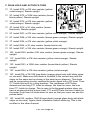
RAMSEY “LEARN-AS-YOU-BUILD” ASSEMBLY STRATEGY
Be sure to read through all of the steps, and check the boxes as you go to be
sure you didn't miss any important steps. Although you may be in a hurry to see
results, before you switch on the power check all wiring and capacitors for
proper orientation. Also check the board for any possible solder shorts, and/or
cold solder joints. All of these mistakes could have detrimental effects on your
kit - not to mention your ego!
Kit building tips:
Use a good soldering technique - let your soldering iron tip gently heat the
traces to which you are soldering, heating both wires and pads simultaneously.
Apply the solder on the iron and the pad when the pad is hot enough to melt the
solder. The finished joint should look like a drop of water on paper, somewhat
soaked in.
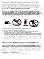
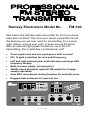
Mount all electrical parts on the top side of the board provided. The top side is
clearly marked with the word “TOP”, you can’t miss it. This is the side that has
little or no traces on it, but is covered with mostly copper. When parts are
installed, the part is placed flat to the board, and the leads are bent on the
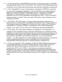
backside of the board to prevent the part from falling out before soldering (1).
The part is then soldered securely to the board (2-4), and the remaining lead
length is then clipped off (5). Notice how the solder joint looks on close up,
clean and smooth with no holes or sharp points (6).
FM-100 Page 11
Since this is a “professional” transmitter, we sincerely hope you put this together in a professional manner. This project will not work as well as you
wished if you just slap it together without following good assembly techniques,
and follow all instructions. No matter how clear we may think our manual is, if
you have any questions give us a call at the factory instead of jumping to conclusions, we will be happy to help you with any problems.
This is a mixed signal project meaning there is digital, audio, and RF circuitry all
in one unit. As with all RF circuitry, we want to mount the parts AS LOW AS
POSSIBLE to the board. A 1/4” lead length on a resistor not mounted close to
the board can act as an inductor or an antenna, causing all sorts of problems in
your circuit. Be aware though that there are stand up components in your circuit. They don’t need to be squished to the board, but keep the portion of the
resistor closest to the board mounted right on the board.
For each part, our word "Install" always means these steps:
1. Pick the correct part value to start with.
2. Insert it into the correct PC board location, making sure the part is
mounted flush to the PC board unless otherwise noted.
3. Orient it correctly, follow the PC board drawing and the written directions
for all parts - especially when there's a right way and a wrong way to solder
it in. (Diode bands, electrolytic capacitor polarity, transistor shapes, dotted
or notched ends of IC's, and so forth.)
4. Solder all connections unless directed otherwise. Use enough heat and
solder flow for clean, shiny, completed connections.
Keeping this in mind, lets begin by sorting out our components and crosschecking them against the parts list to make sure we have received everything.
NOTE TO NEWCOMERS: If you are a first time kit builder you may find this
manual easier to understand than you may have expected. Each part in the kit
is checked off as you go, while a detailed description of each part is given. If
you follow each step in the manual in order, and practice good soldering and kit
building skills, the kit is next to fail-safe. If a problem does occur, the manual
will lead you through step by step in the troubleshooting guide until you find the
problem and are able to correct it.
FM-100 Page 12
RAMSEY FM-100 PARTS LIST
Semiconductors
1 MC145170 Serially programmed PLL (U2)
1 BA1404 Stereo generator IC (U6)
2 LF347 Quad low noise opamps (U11,8)
1 68HC705J2 Custom programmed microcontroller (U4) Marked FM-100
1 X2402 serial EEPROM (U1)
2 LM3915 Log bar-dot bargraph display drivers (U12,U5)
2 MAX291 8th order Butterworth lowpass switched capacitive filters
(U9,10)
1 MC2830 Voice activated switch with AGC (U7)
1 MM5451 Serial shift register display driver (U3)
1 79L08 -8 volt voltage regulator (TO92 package) (VR4)
1 7808 +8 volt voltage regulator (TO-220 package) (VR2)
1 7805 +5 volt voltage regulator (TO-220 package) (VR3)
1 78L02 +2.5 volt voltage regulator (TO-92 package) (VR1)
2 10 segment bargraph displays (D11,12)
2 Small red LEDs (D2, 3)
2 Dual Common Anode LED displays (DS1, 2)
6 1N4002 rectifier diodes (Black with white stripe on one end)
(D6,7,21,22,23,24)
5 1N4148 small signal switching diodes (small orange glass body with
black stripe) (D1,4,5,8,9)
1 BB609 Varactor diode (black diode with green band) (D10)
3 BS170 N-Channel enhancement TMOS FETs (Q4,5,6)
2 2SC2498 or 2570 NPN UHF Bipolar transistors (Q1,2)
2 2N3904 NPN General purpose transistors (Q3,7)
Resistors
1 10 ohm resistor (brown-black-black) (R9)
1 51 ohm resistor (green-brown-black) (R73)
1 100 ohm resistor (brown-black-brown) (R16)
3 270 ohm resistors (red-violet-brown) (R30,32,36)
2 330 ohm resistors (orange-orange-brown) (R1,4)
1 470 ohm resistor (yellow-violet-brown) (R11)
18 1K ohm resistors (brown-black-red) (R18,19,20,29,33,39,44,47,
50,53,59,64,71,76,82,86,87,89)
3 4.7K ohm resistors (yellow-violet-red) (R42,61,69)
1 8.2K ohm resistor (gray-red-red) (R13)
23 10K ohm resistors (brown-black-orange) (R2,5,6,8,10,12,14,17,40,
41,49,55,56,57,60,63,68,70,78,80,83,85,88)
4 15K ohm resistors (brown-green-orange) (R22,27,58,66)
2 22K ohm resistors (red-red-orange) (R31,65)
1 33K ohm resistors (orange-orange-orange) (R24)
FM-100 Page 13
7
4
4
1
1
3
47K ohm resistors (yellow-violet-orange) (R21,28,34,54,67,72,79)
75K ohm resistors (violet-green-orange) (R45,52,77,81)
100K ohm resistor (brown-black-yellow) (R7,51,75,91)
150K ohm resistor (brown-green-yellow) (R46)
220K ohm resistor (red-red-yellow) (R25)
1M ohm resistors (brown-black-green) (R3,38,48)
Ceramic capacitors
1 5pF ceramic capacitor (marked 5 or 5K) (C15)
4 10pF ceramic capacitors (marked 10 or 10K) (C18,27,32,82)
2 27pF ceramic capacitors (marked 27 or 27K) (C1,2)
4 47pF ceramic capacitors (marked 47 or 47K) (C29,31,84,85)
1 75pF ceramic capacitor (marked 75 or 75K) (C30)
6 100pF ceramic capacitors (marked 100 or 101) (C13,40,46,64,70,91)
1 220pF ceramic capacitor (marked 220 or 221) (C34)
15 .001uF ceramic capacitors (marked .001 or 102) (C7,8,14,24,25,26,
28,36,41,45,62,75,87,88,90)
2 .0047uF ceramic capacitors (marked .0047 or 472) (C61,74)
13 .01uF ceramic capacitors (marked .01, 10n, or 103) (C3,10,17,20,
21,48,49,53,54,79,80,81,83)
6 .1uF ceramic capacitors (marked .1 or 104) (C4,9,22,51,66,68)
Electrolytic capacitors
1 1uF electrolytic capacitor (C38)
1 2.2uF electrolytic capacitor (C12)
25 10uF electrolytic capacitors (C6,11,16,19,23,33,35,37,39,42,43,44,56,
58,60,63,65,67,69,71,72,73,76,77,78)
2 47uF electrolytic capacitors (C47,59)
2 100uF electrolytic capacitors (C5,50)
2 1000uF electrolytic capacitors (C55,89)
2 3300uF electrolytic capacitors (C52,86)
Variable Resistors
2 1K ohm trimmers (orange top marked 102) (R23,35)
1 10K ohm board mount pot (R26)
2 10K ohm dual pots (R62,84)
1 100K ohm trimmer (orange top marked 104) (R15)
Inductors
1 adjustable shielded metal can coil or similar (L1)
4 40nH coils (small 4 turn air coils) (L2,3,5,6)
1 Small red torroid core (L4)
8” #26 enamel wire for winding (L4)
FM-100 Page 14
Miscellaneous
1 38KHz crystal (Y2)
1 Mini speaker (SP1)
2 Stereo RCA jacks (J5,6)
1 6 pin Molex connector (J10)
1 4 pin Molex header (J11)
4 5 pin headers (J1,3,7,8)
5 DPDT Push button switches (S1,2,3,4,5)
1 20 pin IC socket
1 3.5mm phono jack (J4)
1 Whip antenna (ANT1)
1 18 pin IC socket
1 PC-20-500 Power transformer (T1)
1 Transformer mounting bracket
1 Heatsink (HS1)
1 6 MHz crystal (Y1)
Case and knob parts
5 Push button switch caps
3 Set screw knobs
1 Bottom case half with pre-attached membrane panel
1 Top case half
14 4-40x1/4 board mounting screws
6 6-32x1/4 self tapping black case screws
2 4-40x5/8 self tapping machine screws
1 Fuse holder with hardware
1 1 Amp fuse
1 110 Volt line cord with plug and pre-installed Molex pins
1 Line cord grommet
1 Antenna grommet
4 Rubber leg pads
1 Chassis mount F connector and mounting nut
1 4” piece of hookup wire
7 4-40 Kepnuts
Other Equipment (Not included)
1 Pencil type soldering iron (30-40 Watts) Don’t use a solder gun!
1 Roll of fine 60/40 solder (less than .045” diameter)
1 Sensitive voltmeter or DMM
1 An FM radio for testing
1 Audio sources such as a tape deck, CD player, or microphone
1 Egg carton or grapefruit holder to sort out parts in.
FM-100 Page 15
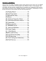
PROJECT ASSEMBLY
Here we go! To make assembly easier and to stick by the “Learn As You Build”
strategy, we will section off the project into different major circuit groups. We
will begin with the smaller display board to perfect your assembly skills before
we continue with the more crowded sections of the board. Following is a list of
all the sections in the manual that we will be going into:
[A] Display Board .................................... 18
[B] Part Preparation ................................ 23
[C] Microphone Amp............................... 24
[D] Mixers................................................. 25
[E] Switched Capacitive Filters ............. 27
[F] Peak Hold and Active Filters............ 29
[G] Transmitter ........................................ 31
[H] Microcontroller .................................. 37
[I] EEPROM Circuit ................................ 38
[J] Jacks and Switches .......................... 39
[K] Power Supply .................................... 41
[L] 1 Watt Module.................................... 44
[M] Rear panel wiring .............................. 45
[N] Front Panel Assembly ...................... 47
[O] PCB Mounting ................................... 47
[P] Final Testing and Calibration........... 48
[Q] Final Case-up .................................... 50
FM-100 Page 16
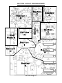
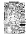
SECTION LAYOUT ON MAIN BOARD
FM-100 Page 17
DISPLAY BOARD LAYOUT
Parts Values
Parts Layout
Note: Gray
components are on
the reverse side of
the board.
FM-100 Page 18
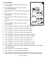
A. DISPLAY BOARD
We will begin with the display board oriented in the direction shown. Be sure
not to confuse the sides of the board where the parts go. On the board you will
see the side marked FRONT, which is where most parts are mounted. We will
begin with lower parts and work up to the higher ones. Don’t use sockets for
these parts since they need to fit between the front panel and the PC board.
1A. Install R87, a 1K ohm resistor (brown-black-red).
2A. Install R59, another 1K ohm resistor (brown-black-red).
3A. Install R13, a 8.2K ohm resistor (gray-red-red). This resistor sets the
current to each of the display segments and LEDs driven from U3.
Lowering the value of this resistor increases the brightness of the display,
but then the display will draw more current. This resistor was selected for
best brightness/current trade-off.
4A. Install U12, one of the LM3915 Log scale bargraph driver ICs. Make
absolutely sure before soldering that you have installed all 18 pins into the
appropriate holes. Also check the notch or dot indicating pin one is facing
in the same direction as shown in the parts layout diagram. Solder all 18
pins, checking for solder bridges when done.
5A. Install U5, the other LM3915 Log scale bargraph driver. Again make
sure all 18 pins are through the board and that the IC is in the correct
orientation.
6A. Install U3, the MM5451 40 pin IC. Again make sure the notch is in the
same direction as shown in the parts layout, and that all 40 pins are
through the board before soldering. This IC drives all the individual
segments of the display without multiplexing it.
7A. Install D12, one of the ten segment bargraph displays. You will notice
a small divot or notch on one corner of the bargraph indicating where pin 1
is. This will be installed in the same orientation as the notch in the parts
layout diagram. Solder all 20 pins.
8A. Install D11, the other 10 segment bargraph display. Make sure to align
this in the same way as before and solder all 20 pins.
9A. Install DS2, one of the two digit displays. Notice how there isn’t any
indication of pin 1 on these. In this case we want to orient the lettering on
the one side towards U3, so that when looking at the display, the lettering
is facing downward. Solder all 18 pins.
10A. Install DS1, the other two digit display. Again orient the lettering
FM-100 Page 19
towards U3 before soldering all 18 pins.
11A. Install D2, one of the small red LEDs. You will notice that if you look
A
Same height
as DS1+DS2
K
1/4"
straight at the LED there is a flat side. This indicates the Cathode side of
the LED. The Cathode side is also indicated by the shorter of the two leads.
Make sure to install the flat side or the shorter lead in the same way as
shown in your diagram. They only light up if they are installed correctly.
Before soldering though, this and the next LED are the only parts that we
do not mound flush to the PC board. In this case we want to mount them so
the lens of the LED is at the same height as DS1 and DS2. These LEDs will
eventually be lining up with holes in the front panel. Once the height is set,
bend the leads to hold the LED in place, then solder.
12A. Install D3 in the same fashion, making sure it is at the same height
and orientation as in the previous step.
Now would be a good time to check all of your solder connections for opens
and solder bridges on the back side of the board. Now we are moving on to
install jumper connections and a capacitor on the back side of the board. The
parts on the back side of the board are marked in gray instead of black.
13A. Install J3, a five pin jumper block, short leads go into the board. Again
make sure you are putting them in the opposite side of the board from
where the rest of the parts are located. This jack is where the numeric
display gets its power and the data for display values.
14A. Install J7, another five pin jumper block. This is where the power for
the bargraphs is applied and the signal levels for the bargraphs are sent.
15A. Install C78, a 10uF electrolytic capacitor. Notice this is the first
capacitor of this type. You want to be sure that you pay close attention to
the polarity markings on this part. In most cases the negative (-) side is
marked on the capacitor, while the positive side (+) is marked on the parts
layout. If you fail to mount this component correctly, the part can fail as well
as prevent proper operation of your project. We will be installing many more
of these later in the project so be sure and remember this!
Cool! We have just completed the display board and we are almost ready to
move on. First we want to check our display board to make sure there are no
solder bridges or cold solder joints. Next check orientation of your parts for
correct installation.
FM-100 Page 20
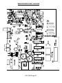
MAIN BOARD PART VALUES
FM-100 Page 21
MAIN BOARD PART LAYOUT
FM-100 Page 22
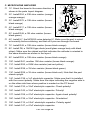
B. PART PREPARATION
Well, there isn’t a heck of a lot to do in these next couple of stages, but these
steps will help the rest of the kit go smoothly if we get them over with now.
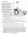
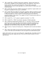
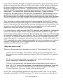
1.) Create L4:
Using the small red torroid core and the piece of enameled wire provided with
your kit, make a coil consisting of 9 turns. To do this simply thread the wire
through the torroid core 9 times as shown here. When done winding, use a hot
soldering iron and fresh solder to tin the ends of the wire. This takes a little
heat and patience, but the enamel will burn off without any need for scraping.
Set this part aside for section H.
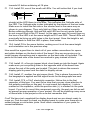
2.) S1,2,3,5 Switch Modification:
We want to modify all but one of the switches to be momentary contact instead of latching switches. To do this there is a little metal latching mechanism
on the front top of the switch. The end of the metal latch furthest from the button end is gently lifted up and out to the side, while the other end remains in
place to keep the spring there.
FM-100 Page 23
C. MICROPHONE AMPLIFIER
1C. Orient the board in the same direction as
shown in the parts layout diagram.
2C. Install R24, a 33K ohm resistor (orangeorange-orange).
3C. Install R70, a 10K ohm resistor (brownblack-orange)
4C. Install R17, a 10K ohm resistor (brownblack-orange)
5C. Install R48, a 1M ohm resistor (brownblack-green).
6C. Install U7, the MC2830 voice detector IC. Make sure the part is oriented correctly before soldering, and that all 8 pins are through the board.
7C. Install R49, a 10K ohm resistor (brown-black-orange).
8C. Install D8, a 1N4148 type diode (small glass orange body with black
stripe). Make sure the striped end that indicates the cathode is oriented in
the same direction as shown in the layout.
9C. Install R55, a 10K ohm resistor (brown-black-orange).
10C. Install R41, another 10K ohm resistor (brown-black-orange).
11C. Install R25, a 220K ohm resistor (red-red-yellow).
12C. Install R38, a 1M ohm resistor (brown-black-green).
13C. Install R29, a 1K ohm resistor (brown-black-red). Note that this part
stands upright.
14C. Install C38, a 1uF electrolytic capacitor. Make sure that it is installed
with the correct polarity. Make sure the stripe indicating the negative side is
on the other side from where positive is marked on the PC board.
15C. Install C33, a 10uF electrolytic capacitor. Check polarity!
16C. Install C42, a 10uF electrolytic capacitor. Polarity!
17C. Install C59, a 47uF electrolytic capacitor. Again check polarity!
18C. Install C39, a 10uF electrolytic capacitor. Orientation!
19C. Install C12, a 2.2uF electrolytic capacitor. Polarity again!
20C. Install C47, a 47uF electrolytic capacitor.
FM-100 Page 24
D. AUDIO MIXER
1D. Install R83, a 10K ohm resistor (brownblack-orange).
2D. Install R88, another 10K ohm resistor
(brown-black-orange)
3D. Install R86, a 1K ohm resistor (brown-blackred)
4D. Install R91, a 100K ohm resistor (brownblack-yellow).
5D. Install R65, a 22K ohm resistor (red-redorange).
6D. Install R50, a 1K ohm resistor (brown-blackred).
7D. Install R80, a 10K ohm resistor (brownblack-orange).
8D. Install R85, a 10K ohm resistor (brown-black-orange).
9D. Install R89, a 1K ohm resistor (brown-black-red).
10D. Install R31, a 22K ohm resistor (red-red-orange).
11D. Install R47, a 1K ohm resistor (brown-black-red).
12D. Install R57, a 10K ohm resistor (brown-black-orange).
13D. Install R63, a 10K ohm resistor (brown-black-orange).
14D. Install R71, a 1K ohm resistor (brown-black-red).
15D. Install R64, a 1K ohm resistor (brown-black-red).
16D. Install R68, a 10K ohm resistor (brown-black-orange).
17D. Install R60, a 10K ohm resistor (brown-black-orange).
18D. Install C63, a 10uF electrolytic capacitor. Make sure to check polarity
for all electrolytics!
19D. Install C69, a 10uF electrolytic capacitor.
20D. Install C43, a 10uF electrolytic capacitor.
21D. Install Q4, a BS170 FET. When looking at this part, you will notice
that the center lead is bent slightly opposite of how we are going to install
FM-100 Page 25
it. Don’t let this confuse you, so make sure the flat side of the transistor is
in the same orientation as shown in the parts layout.
22D. Install C81, a .01uF ceramic capacitor (marked .01, 10n, or 103).
This cap is used to filter out noise on the gates of Q5 and Q6.
23D. Install Q5, another BS170 FET. Make sure and mount the flat side in
the same orientation as shown in the layout.
24D. Install U8, one of the LF347 quad low noise opamps. Make sure the
dot or tab indicating pin 1 is installed in the same orientation as the tab
shown in the layout. Solder all 14 pins while making sure each pin has
been inserted into the board.
25D. Install C58, a 10uF electrolytic capacitor. Check polarity!
26D. Install C72, another 10uF electrolytic capacitor.
27D. Install C73, yet another 10uF electrolytic capacitor.
28D. Install C76, even another 10uF electrolytic capacitor.
29D. Install C77, a 10uF electrolytic capacitor.
30D. Install C80, a .01uF ceramic capacitor (marked .01, 10n, or 103).
31D. Install Q6, the last of the BS170 FETs. Again make sure that the flat
side is installed in the same orientation as shown in the layout.
Now it’s time to move on to the next section of our project, but maybe you
want to take an eyeball break first. Not including the pots that will be used for
control, the mixer and microphone sections are now complete. This would be
a good time to go through and check your work for good assembly practice.
Check for solder bridges, cold solder joints, and improperly oriented devices.
A common practice among engineers and techs at the factory when you can’t
find a mistake is to get up, take a short break and come back with a new perspective. You would be surprised how many problems you can find when you
do this. Sort of like getting up and leaving one marriage for a fresh, new perspective?
Onward!
FM-100 Page 26
E. SWITCHED CAPACITOR FILTERS
1E. Locate the center of the board where this
group of parts is to go.
2E. Install R45, a 75K ohm resistor (violetgreen-orange).
3E. Install R53, a 1K ohm resistor (brownblack-red).
4E. Install R52, a 75K ohm resistor (violetgreen-orange). This part stands upright.
5E. Install R81, a 75K ohm resistor (violetgreen-orange). Another stand-up.
6E. Install R66, a 15K ohm resistor (browngreen-orange). This resistor isn’t actually associated with this section but it
forms part of the active lowpass filter in the next section. Another standup.
7E. Install R77, a 75K ohm resistor (violet-green-orange).
8E. Install R82, a 1K ohm resistor (brown-black-red).
9E Install R61, a 4.7K ohm resistor (yellow-violet-red).
10E. Install R69, another 4.7K ohm resistor (yellow-violet red). This
resistor and R61 form a voltage divider for the MAX291 ICs opamps since
they need to run from the +5 volt supply. The divider creates 2.5 volts
which is the center voltage around the audio signal coming in.
11E. Install R78, a 10K ohm resistor (brown-black-orange).
12E. Install R56, a 10K ohm resistor (brown-black-orange).
13E. Install U10, one of the MAX291 filter chips. Make sure the part is
oriented correctly before soldering. Also make sure all eight pins are
through the board before soldering. It is a common mistake to install an IC
with one of the pins folded under the IC instead of through a hole.
14E. Install U9, the other MAX291 filter chip. Again check orientation and
the pins before soldering.
15E. Install C46, a 100pF ceramic capacitor (marked 100 or 101).
16E. Install C61, a .0047uF ceramic capacitor (marked .0047 or 472).
17E. Install C62, a .001uF ceramic capacitor (marked 102 or .001).
FM-100 Page 27
18E. Install C44, a 10uF electrolytic capacitor, check the polarity before
soldering!
19E. Install C67, a 10uF electrolytic capacitor (polarity).
20E. Install C75, a .001uF ceramic capacitor (marked 102 or .001).
21E. Install C74, a .0047uF ceramic capacitor (marked .0047 or 472).
22E. Install C70, a 100pF ceramic capacitor (marked 100 or 101).
23E. Install C66, a .1uF ceramic capacitor (marked .1 or 104).
24E. Install C65, a 10uF electrolytic capacitor. Check its installation!
Check you work up to this point to be sure you didn’t mess up. It is much
easier to check you work in small manageable groups than all at once. Again
check for solder bridges and cold solder joints. Especially check around the
pins of the ICs for solder bridges since it is a common occurrence.
FM-100 Page 28
F. PEAK HOLD AND ACTIVE FILTERS
1F. Install R79, a 47K ohm resistor (yellowviolet-orange). Stands upright.
2F. Install R75, a 100K ohm resistor (brownblack-yellow). Stands upright.
3F. Install R72, a 47K ohm resistor (yellowviolet-orange). Stands upright.
4F. Install R76, a 1K ohm resistor (brownblack-red). Stands upright.
5F. Install R67, a 47K ohm resistor (yellow-violet-orange). Stands upright.
6F. Install R58, a 15K ohm resistor (brown-green-orange). Stands upright.
7F. Install R34, a 47K ohm resistor (yellow-violet-orange).
8F. Install R44, a 1K ohm resistor (brown-black-red).
9F. Install R27, a 15K ohm resistor (brown-green-orange). Stands upright.
10F. Install R22, another 15K ohm resistor (brown-green-orange). Stands
upright.
11F. Install R28, a 47K ohm resistor (yellow-violet-orange). Stands
upright.
12F. Install R51, a 100K ohm resistor (brown-black-yellow). Stands
upright.
13F. Install R54, a 47K ohm resistor (yellow-violet-orange).
14F. Install D9, a 1N4148 type diode (orange glass body with black stripe
on one end). Make sure this diode is installed in the correct way with the
stripe on the same end as shown in the parts layout diagram. This diode
and its surrounding circuitry rectifies the audio signal into a DC level. Then
C71 holds this level for a long duration. The resistance of R79 then
determines how long C71 holds its charge, the less the value, the less
time C71 holds its charge. This is seen in the bargraph meters when you
have a single pulse like a drum beat. C71 and R79 set the time it takes for
the meter to go from full scale down to zero so that your eyes can see the
pulses better.
15F. Install D4, another 1N4148 type diode (orange glass body with black
stripe on one end). Again check orientation before soldering. This is the
rectifier for the other channel.
FM-100 Page 29
16F. Install J8, a 5 pin jumper header. Make sure and leave the longer
leads facing up, with the shorter ends soldered to the board. This is where
the connection is made to the front panel.
17F. Install C71, a 10uF electrolytic capacitor. Check polarity!
18F. Install C60, another 10uF electrolytic capacitor.
19F. Install C68, a .1uF ceramic capacitor (marked .1 or 104).
20F. Install C64, a 100pF ceramic capacitor (marked 100 or 101).
21F. Install C51, a .1uF ceramic capacitor (marked .1 or 104).
22F. Install C40, a 100pF ceramic capacitor (marked 100 or 101).
23F. Install C88, a .001uF ceramic capacitor (marked 102 or .001).
24F. Install C45, a .001uF ceramic capacitor (marked 102 or .001).
25F. Install U11, a LF347 low noise opamp. Make sure and orient it in the
same direction as shown in the parts layout. Also check for all 14 pins to
be through the board before soldering.
26F. Install R23, one of the 1K ohm trim pots (orange Philips top marked
102).
27F. Install R35, the remaining 1K ohm trim pot (orange Philips top
marked 102).
Well, that’s it for the peak hold circuits and the 15KHz low pass filter. Quick
and painless, wasn’t it? We have to go back now and check all our work to
make sure that we didn’t install anything in the wrong way or have any
soldering errors such as bridges and cold solder joints. When you’re done, go
grab a soda (preferably caffeinated) and give yourself an eyeball break.
Our next section is the toughest of the whole kit, so make sure you have all of
your skills primed and ready for the true test!
FM-100 Page 30
G. TRANSMITTER
This is where we definitely want to
have clean soldering skills and
proper mechanical mounting of
parts. If you need a review, shoot
back to the start of the manual in the
“STRATEGY” section for tips. Make
sure all your parts are flush to the
board and not waving in the breeze.
You will not only lose performance if
parts aren’t installed correctly, but
your kit may not work at all. Have
patience and follow all directions
and you should have no trouble at
all!
1G. Install JMP5 using a scrap piece of lead wire. Leave the jumper “loop”
about 1/4” above the board to allow you to cut it out later. If you wish to
operate the FM-100 in mono, this is the jumper you would cut.
2G. Install Y2, the 38KHz crystal found taped to
a piece of paper. Before mounting, bend the
leads so that they don’t short to ground when
installed. We want to install the part in a laydown fashion so that we can strap the crystal to the board with a jumper
so that it is secured in place. Lay it down in the orientation shown, then
use a scrap piece of lead to make a loop over the crystal to hold it tightly
to the board. You can’t miss the two holes where this loop is mounted to.
3G. Install the 18 pin IC socket. Make sure all the leads are though the
board before soldering. Install U6, the BA1404 stereo generator IC, making sure that the part is installed in the correct orientation.
4G. Install R46, a 150K ohm resistor (brown-green-yellow).
5G. Install R42, a 4.7K ohm resistor (yellow-violet-red).
6G. Install R15, a 100K ohm trim pot (orange Philips top marked 104).
This will adjust the MPX balance of the internal workings of the BA1404.
Normally this control is at center position.
7G. Install R3, a 1M ohm resistor (brown-black-green). This resistor helps
Y1 begin to oscillate when the unit is first turned on by biasing an internal
inverter in U2 into a linear range.
8G. Install R7, a 100K ohm resistor (brown-black-yellow).
FM-100 Page 31
9G. Install R16, a 100 ohm resistor (brown-black-brown).
10G. Install R11, a 470 ohm stand up resistor (yellow-violet brown). Be
sure to install it exactly as shown in the parts layout. We will be using the
exposed end later during testing procedures.
11G. Install R36, a 270 ohm resistor (red-violet-brown).
12G. Install R40, a 10K ohm stand up resistor (brown-black-orange).
13G. Install R32, another 270 ohm resistor (red-violet-brown).
14G. Install R73, a 51 ohm stand up resistor (green-brown-black). This
resistor is used on the RF output of U6 to give the BA1404 a resistive load
to drive.
15G. Install R30, a 270 ohm resistor (red-violet-brown).
16G. Install U2, the MC145170 PLL. Make sure that the dot or tab indicating pin 1 is in the same direction as shown in the parts layout diagram.
Solder all 16 pins.
17G. Install R8, a 10K ohm resistor (brown-black-orange).
18G. Flip the board over and find the hole where the whip antenna
mounts. Insert the antenna screw (4-40X1/4) into the hole so that the
threads are pointing to the parts side of the board. Use ample heat to solder the screw in place. You may scrape off some of the screw’s plating to
make it solder better.
19G. Install L3, one of the 4 turn 40nH coils.
20G. Install L2, another 4 turn 40nH coil.
21G. Install L5, yet another 4 turn 40nH coils.
22G. Install L6, the last 4 turn 40nH coil.
23G. Install L4, the custom wound coil that you made earlier. Make sure to
mount this part low to the board and that you are soldering to the copper
of the wire and not the insulation.
24G. Install C31, a 47pF ceramic capacitor (marked 47 or 47K).
25G. Install C30, a 75pF ceramic capacitor (marked 75 or 75K).
26G. Install C29, a 47pF ceramic capacitor (marked 47 or 47K).
27G. Install C9, a .1uF ceramic capacitor (marked .1 or 104).
28G Install C14, a .001uF ceramic capacitor (marked .001, or 102).
FM-100 Page 32
29G. Install C21, a .01uF ceramic capacitor (marked .01, 10n or 103).
30G. Install C20, a .01uF ceramic capacitor (marked .01, 10n or 103).
31G. Install C24, a .001uF ceramic capacitor (marked .001 or 102).
32G. Install C26, a .001uF ceramic capacitor (marked .001 or 102).
33G. Install C85, a 47pF ceramic capacitor (marked 47 or 47K).
34G. Install C82, a 10pF ceramic capacitor (marked 10 or 10K).
35G. Install C84, a 47pF ceramic capacitor (marked 47 or 47K).
36G. Install C28, a .001uF ceramic capacitor (marked 102 or .001).
37G. Install C90, a .001uF ceramic capacitor (marked 102 or .001).
38G. Install C13, a 100pF ceramic capacitor (marked 100 or 101).
39G. Install C18, a 10pF ceramic capacitor (marked 10 or 10K).
40G. Install C15, a 5pF ceramic capacitor (marked 5 or 5K).
41G. Install C27, a 10pF ceramic capacitor (marked 10 or 10K).
42G. Install C32, a 10pF ceramic capacitor (marked 10 or 10K).
43G. Install C87, a .001uF ceramic capacitor (marked .001 or 102).
44G. Install C19, a 10uF electrolytic capacitor. Make sure and check its
correct polarity before soldering!
45G. Install C41, a .001uF ceramic capacitor (marked .001 or 102).
46G. Install C23, a 10uF electrolytic capacitor. Check polarity!
47G. Install C36, a .001uF ceramic capacitor (marked .001 or 102).
48G. Install C16 a 10uF electrolytic capacitor. Again orientation!
49G. Install C8, a .001uF ceramic capacitor (marked .001 or 102).
50G. Install C35, a 10uF electrolytic capacitor. Check to be sure it’s in the
right way.
51G. Install C25, a .001uF ceramic capacitor (marked .001 or 102).
52G. Install C6, a 10uF electrolytic capacitor. Polarity!
53G. Install C1, a 27pF ceramic capacitor (marked 27 or 27K).
54G. Install C2, another 27pF ceramic capacitor (marked 27 or 27K).
FM-100 Page 33
These capacitors give the crystal the proper loading so that it operates on
the correct frequency. In the FM band, our crystal can be off by as much
as .01% and most tuners will pick it up just fine. As this crystal is set up, it
will be within .001%, which is 10X better, and that’s without tuning!
55G. Install C34, a 220pF ceramic capacitor (marked 220K or 221).
56G. Install C7, a .001uF ceramic capacitor (marked .001 or 102).
57G. Install C11, a 10uF electrolytic capacitor. Check polarity!!!
58G. Install D10, the BB609 varactor diode (black diode with a green
band). The PC board silkscreen for this part looks like a transistor so you’ll
need to be careful to get the orientation right when installing this varactor
diode. The banded cathode end should be placed in the hole closest to
C13. Adjusting the voltage across this diode allows the PLL to do its job.
When in use, this diode is reverse biased so it actually acts as a capacitor.
When the voltage across the diode is high, the depletion layer internal to
the diode gets wider. This causes the capacitance to lower so that the oscillator changes frequency.
59G. Install Q2, one of the 2SC2498 UHF transistors. Make darn sure the
flat side is oriented as shown in the parts layout diagram. Notice because
these are not a standard transistor, the pin-out is not C-B-E like with
2N3904 transistors, instead it is B-E-C (Base Emitter Collector).
60G. Install Q1, the other 2SC2498 UHF transistor. Again make sure the
flat side is in the correct direction.
61G. Install VR1, the 78L02 2.5 volt regulator. Be sure the flat side is in the
right direction before soldering. This regulator only powers the BA1404.
62G. Install L1, the shielded metal canned coil. Solder both the mounting
lugs and the two connections. Be careful that you don’t bend over one of
the connections before it goes through the board, these are a pain in the
neck to desolder.
63G. Install Y1, the 6.00MHz crystal (Silver metal can marked 6.00). Make
sure and mount this part flush to the board.
Whew! That was a lot of steps. Definitely check all of your work up to this point
for mistakes in orientation. Double check all of your electrolytic capacitors to be
sure the positive symbols are on the opposite side of the negative stripe. Also
make sure there are no solder bridges or cold solder joints.
If there are no problems up to this point it is time to move on! Now we are on to
easier stuff with less steps. But still be careful of your assembly, you wouldn’t
want to get this far and then make a mistake causing the project not to work.
With soldering iron in hand, on to the next section!
FM-100 Page 34
H. MICROCONTROLLER
This section is a little vague in what’s
entailed. The microcontroller really controls
the entire circuit, but this section deals with
the parts which are fairly exclusive to the
controller itself. We’ll wait until later to install
the switches because they get in the way
while we’re installing the rest of the parts.
1H. Install R21, a 47K ohm resistor
(yellow-violet-orange).
2H. Install R20, a 1K ohm resistor
(brown-black-red).
3H. Install R18, a 1K ohm resistor
(brown-black-red).
4H. Install R6, a 10K ohm resistor (brown-black-orange).
5H. Install R10, a 10K ohm resistor (brown-black-orange).
6H. Install R12, another 10K ohm resistor (brown-black-orange).
7H. Install R14, yet another 10K ohm resistor (brown-black-orange).
8H. Install R19, a 1K ohm resistor (brown-black-red).
9H. Install Q3, a 2N3904 switching transistor. Make sure when installing
that the flat side is facing in the same direction as shown in the layout.
10H. Install SP1, the mini speaker. Make sure the + terminal of the
speaker is facing towards C50, but away from Q3. This is where
confirming tones are sounded when a button is depressed.
11H Install the 20 pin IC socket for U4. If the socket has a notch in one
end, install it at the same end the layout shows to prevent confusion later.
12H. Install R9, a 10 ohm resistor (brown-black-black). This resistor limits
the volume of the speaker.
13H. Install R5, a 10K ohm resistor (brown-black-orange).
14H. Install C22, a .1uF ceramic capacitor (marked .1 or 104).
15H. Install C17, a .01uF ceramic capacitor (marked .01, 10n or 103).
16H. Install J1, a 5 pin jumper header. Make sure the shorter ends are
installed into the board. This will be the connection to the digit display.
FM-100 Page 35
17H. Install D1, a 1N4148 type diode (orange glass body with black stripe
on one end). Install it in the same orientation as shown in the parts layout
diagram.
18H. Install U4, the IC with the sticker FM-100 into the socket.If your chip
has a dot or notch, orient as shown in the parts layout diagram. If your chip
has a large “1” on one end, this end is oriented as though it were a notch. It
should be placed at the end of the socket closest to R19. This is the
“brains” of your project, keeping track of all the button presses, the
frequency lock, and the rest of the circuit. Be sure all 20 pins are firmly in
the socket and none are bent under.
19H. Install C37, a 10uF electrolytic capacitor (Check polarity!).
20H. Install Q7, a 2N3904 type transistor. Make sure and mount the flat
side in the same orientation as shown in the parts layout diagram.
Now is another good time to check all of your work for soldering and installation
problems before we move on to the EEPROM circuit.
I. EEPROM
EEPROM is where the operating frequency
last used is stored so that the next time you
power up the unit, it goes right back to that
frequency. It sure beats having to remember
the frequency and have to re-enter it each
time you power it up!
1I. Install R1, a 330 ohm resistor
(orange-orange-brown).
2I. Install R2, a 10K ohm resistor (brown-black-orange).
3I. Install R4, a 330 ohm resistor (orange-orange-brown).
4I. Install C3, a .01uF ceramic capacitor (marked .01, 10n or 103).
5I. Install U1, the X2402 EEPROM IC. Make sure that the notch or dot is
installed in the same orientation as shown in the parts layout diagram.
The resistors in this part of the circuit prevent bus contention when the
microcontroller and the EEPROM are talking back and forth. The EEPROM
uses a two wire serial interface. The data line goes between an input and
output depending if you are writing or reading data from the EEPROM. Since
the microcontroller doesn’t entirely know when the EEPROM is switching
between input and output, we don’t want to drive an output with an output by
accident. The resistors prevent an output from driving another output directly.
FM-100 Page 36
J. JACK AND SWITCHES:
Now our project will begin to look
complete as we install the jacks and
switches. We only have one component
section to go after we complete this, so
be sure not to lessen the effort you put
into making a nice neat project out of this.
1J. Install S4, an unmodified switch
that we left alone in section B. Make
sure when mounting all of your
switches that they are pressed firmly
to the board so that they will align
properly in the case holes when
completed.
2J. Install S1, the FREQUENCY UP
switch. This is one of the modified
switches.
3J. Install S2, the FREQUENCY
DOWN switch.
4J. Install S3, the MIC IN switch.
5J. Install S5, the AUTO AGC switch.
6J. Install R84, one of the dual 10K ohm potentiometers. Install this part
so that its shaft is perfectly parallel to the PC board before soldering. It is
easy enough to reheat the pads and adjust the pots so they align properly
to the holes if you make a mistake.
7J. Install R62, the other dual 10K ohm potentiometer. Make sure the post
is parallel with the PC board before soldering.
8J. Install R26, the single 10K ohm potentiometer. Solder all three pins as
well as solder the two mounting lugs as well.
9J. Install J4, the microphone jack. Solder all 5 pins.
10J. Install J10, the six pin Molex connector. Make sure and mount the
short ends in the PC board. Also notice that the board layout shows only
the female connector of the 1 watt module, not the male connector that we
are installing.
11J. Install J5, one of the stereo RCA jacks. Make sure and mount these
so the back is square in relation to the PC board and that the jack is
mounted flush to the PC board.
FM-100 Page 37
12J. Install J6, the other stereo RCA jack. When installing, make sure it is
installed to nicely meet up with J5 and that it is flush with the PC board as
well.
13J. Install J11, a four pin Molex header connector. Make sure the short
ends are the ones installed in the PC board.
That takes care of all of the jacks and switches. Now we want to give the FM100 a thorough check over with the most picky eye that you possess. We
have installed many parts up to this point in time and chances are you have
made a mistake somewhere. Even the best of kit assemblers are known to
make mistakes when putting their kits together, and feel pretty ridiculous when
they get their kit back from repair with a solder bridge fixed or a part installed
backwards (whoops!). We just want to make sure you don’t need to send back
this for something easily repaired yourself. To assist you in checking your
project out, have an associate check your work for you, you may be surprised
what they point out for you!
FM-100 Page 38
K. POWER SUPPLY
Oh yes! the final section of our
project and then on to testing and
playing! Don’t rush now, this
section has many parts that are
very critical in orientation,
especially the large electrolytic
capacitors. If they are installed in
reverse, the electrolyte in the
capacitor begins to boil creating a
grand amount of pressure inside a
metal can part. Even though they
have stress relief on the tops, they
still tend to explode like a
firecracker. After all this work we
certainly don’t want that to happen!
1K. Install D21, a 1N4002 type
rectifier diode (black body with
white stripe on one end or larger orange body with thick leads and black
stripe). Make sure the end with the stripe is installed in the same
orientation as shown.
2K. Install D22, another 1N4002 type rectifier diode. Again make sure the
striped end is installed correctly.
3K. Install D23, a 1N4002 type rectifier diode (orientation!).
4K. Install D24, another 1N4002 type rectifier diode (line end installed
correctly?) The four diodes we installed form a bridge rectifier providing us
with a DC voltage from an AC source.
5K. Install C48, a .01uF ceramic capacitor (marked .01, 10n or 103).
6K. Install C49, a .01uF ceramic capacitor (marked .01, 10n or 103).
7K. Install C53, a .01uF ceramic capacitor (marked .01, 10n or 103).
8K. Install C54, another .01uF ceramic capacitor (marked .01, 10n or
103). These four diodes that we just installed prevent 60Hz hum in a high
noise environment like a transmitter. When the diodes are busy switching
on and off during an AC cycle, the RF impedance of the power supply
changes slightly, causing amplitude modulation in the RF on the power
supply (there is always going to be some present in varying degrees). This
RF modulation is detected in some circuits like opamps and the BA1404
causing 60Hz hum and other noises. The capacitors reduce the problem
dramatically when placed across each diode.
FM-100 Page 39
9K. Install D6, a 1N4002 type diode. Make sure the striped end is installed
correctly!
10K. Install D7, the last 1N4002 type rectifier diode. Again check the
striped end for correct installation.
11K. Install VR4, the 79L08 -8 volt regulator. Make sure the flat side of the
part is oriented as shown. This part “smoothes” out the raw DC from C55.
12K. Install C56, a 10uF electrolytic capacitor. Make sure the negative
side of the capacitor is installed on the opposite side of where the positive
side marked on the board is.
13K. Install C55, a 1000uF electrolytic capacitor. (Watch polarity!)
14K Install C89, another 1000uF electrolytic capacitor. (Polarity) The last
group of parts have formed a negative voltage multiplier to give us our
minus supply for the opamps.
15K. Install C50, a 100uF electrolytic capacitor. Again check the polarity
before installing.
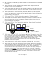
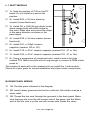
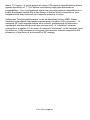
Heatsink
7805
Topside
PC Board
16K. Install VR3, the 7805 +5 volt power regulator. We want to mount this
flat to the board as shown in the diagram. The tab side of the part should
be facing the board. Install HS1 between the tab and the PC board. Make
sure the heatsink is installed so that it doesn’t hit the leads of the
regulator. Use a 4-40x1/4 screw and a lock nut to secure the regulator,
heatsink and board together.
17K. Install C10, a .01uF ceramic capacitor (marked 103, .01 or 10n).
18K. Install T1, the power transformer (PC-20-500). Notice how the label
of the transformer has an orientation dot on one corner. A corresponding
dot is located on the PC board silk screen for T1. When installing T1,
ensure that the dot on the transformer is oriented to the same corner as
indicated on the board. Make sure you install this correctly! If installed
wrong, you will destroy your entire kit! You may need to bend the leads
around a little before installing in the board. Make sure all six pins are
through before soldering.
FM-100 Page 40
19K. Install C86, a 3300uF electrolytic capacitor. Notice how there are
three holes available for the negative side of the capacitor. Only one of
these needs to be used by the capacitor. These holes just make
allowances for various lead spacings, just use the best fit. Make sure and
check polarity!
20K. Install C52, the other 3300uF electrolytic capacitor. Again make sure
the part is installed in the correct orientation.
21K. Install VR2, the 7808 +8 volt power regulator. Before soldering, bend
the part over while installed in its holes. Make sure the tab does not short
to the trace above it. Use a 4-40x1/4 screw and lock nut to hold the
regulator tightly to the board. The copper of the PC board works well as a
heat sink for this part.
22K. Install C4, a .1uF ceramic capacitor (marked .1 or 104)
23K. Install C5, a 100uF electrolytic capacitor (Watch polarity!).
24K. Install the transformer bracket over T1. Use four 4-40x1/4 screws
and 4 lock nuts on the top side of the board to hold the transformer in
place. Be sure to place the lock nuts on the top side of the board. If
tightened on the bottom they may short out the power line!
25K. Locate a 4” piece of hookup wire . Strip back and tin each end about
1/4”.
26K. Insert and solder one end into the hold marked ‘A’ near the antenna
screw. The other end will attach to the rear panel mounted antenna jack.
Again check all of your work up to this point, especially the orientation of all of
the parts in the power supply section. Now we will install the parts for the 1
watt module.
FM-100 Page 41
L. 1 WATT MODULE
1L. Note the position of C92 on the PC
board. Do not install any part in this
position.
2L. Install R33, a 1K ohm stand up
resistor (brown-black-red).
3L. install D5, a 1N4148 type diode (small
glass orange body with black stripe on
one end). Make sure and mount the stripe
in the same direction as shown in the
parts layout.
4L. Install R39, a 1K ohm resistor (brownblack-red).
5L. Install C91, a 100pF ceramic
capacitor (marked 100 or 101).
6L. Install C79, a .01uF ceramic capacitor (marked 103, .01 or 10n).
7L. Install C83, a .01uF ceramic capacitor (marked 103, .01 or 10n).
8L. Using a scrap piece of component wire, install a wire in the hole
marked TP2. Make sure this wire is long enough to connect a DMM meter
probe to.
This section of parts will not be needed until you install the 1 watt module.
Check all of your parts for correct installation and clean solder connections.
M. REAR PANEL WIRING
1M. Find the parts indicated in the diagram.
2M. Insert rubber grommet into the line cord hole, this will be used as a
strain relief.
3M. Thread the line cord through the grommet in the back panel. Make
sure the plug end is on the silk screen side of the panel, and the Molex
end of the line cord is on the non-silk screen side (inside the case).
FM-100 Page 42
4M. Your 110VAC line cord has three wires; black, white, and green. The
black wire does not have a factory installed Molex pin on it; this is the
HOT side of the power connection. Strip and tin the end of the black wire.
5M. Locate the female Molex connector and insert the white linecord wire,
as shown, into the jack. You will notice there is a small catch tab on one
side of the pin. Insert the pin into the Molex jack so the tab faces the side
with the slotted holes. You should hear a small “click” when installed
properly.
6M. Install the center green wire and pin into either of the center holes of
the Molex jack. Make sure it clicks into place. Both the center holes are
connected together on the PC board.
7M. Install the 3” piece of line cord wire with Molex pin attached into the
other side of the Molex jack.
8M. Install the fuse holder in the back of the case so that the cap is on the
FM-100 Page 43
silkscreened side of the panel. Mount the plastic nut between the silk
screened side of the case and the cap. Make sure the plastic nut is
tightened well on the inside so it doesn’t become loose later.
9M. Bend the pre-tinned end of the 3” piece into a quarter loop so that it
holds onto the solder tab of the fuse holder for soldering. Solder the wire
to the end tab of the fuse holder.
10M. Bend the end of the black wire tinned in step 4M into a quarter loop
so that it holds to the side tab of the fuse holder. Solder this wire to the
side tab of the fuse holder.
11M. Thread about 3” of the line cord through the back so there is some
wire length to play with inside the case.
12M. Make sure the fuse is installed in the fuse holder.
13M. Plug in the Molex plug onto the Molex strip J11.
14M. Locate the chassis mount F connector. Mount it to the rear panel
using the included hardware.
15M. Solder the wire from point ‘A’ on the PC board to the center pin of
the F connector.
That should take care of that! We are almost ready to plug it in the wall and
give her a run. But first we want to check everything we have done up to this
point very closely. Especially the circuitry involved with the 110 VAC
connections. Check and double check your wiring against that shown in the
diagram. Also make sure that the two high voltage connections are to either
side of the Molex plug, and not in the center. The green wire of the line cord is
Earth ground, not a high voltage connector and can be connected to either of
the center pins.
Be very careful around these connections, because when we plug it in, it will
be live! Especially be careful of the power switch S1, the top pins on the
switch are connected directly to the ones mounted in the PC board, so
110VAC will be present on those also. When we have finished checking out
the project, you may coat these connections with insulating glue such as
epoxy or silicone glues such as tub sealant.
FM-100 Page 44
N. FRONT PANEL ASSEMBLY
1N. Align the front panel PC board with the holes in the front panel assembly.
2N. Check the LEDs for proper installation height and positioning. If they
are misaligned, now is a good time to correct that.
3N. Using 3 of the the 4-40x1/4 screws, mount the board securely to the
front panel.
4N. Admire your work up to this point. (WOW!)
O. PC BOARD MOUNTING AND CASING
To make testing of the PC board easier, it is convenient to have the PC board
mounted to the bottom of the case. This keeps down the possibility of wires
crossing or metal objects shorting out across the back of the PC board.
1O. Mount the main board to the bottom of the case making sure the
holes line up with the standoffs in the bottom. Note that you will be installing 5 board screws; the screw under the power switch is not used.
2O. Using one of the pre-made 5 wire jumper connectors, connect from J8
to J7. Make sure pin 1 of J7 is connected to pin 1 of J8. To check this you
can see what pins are connected to the ground plane.
3O. Using the other 5 wire jumper connector, connect from J1 to J3. Again
make sure that pin 1 of J3 is connected to pin 1 of J1.
4O. Connect the 4 pin Molex connector from the rear panel to J11 on the
main board. You can then set the cover in place without having to screw it
down until your initial tests are made.
Now we are getting somewhere! Is it ever tempting to plug it in. But wait, flip
the page first!
FM-100 Page 45
P. FINAL TESTING AND CALIBRATION
We’re almost ready to plug it in. We will need the following equipment to give
it a true test.
A DMM or voltmeter.
A sound source such as a CD player or tape deck.
A microphone with the appropriate jack.
A receiver (preferably digital tuner).
The tuning tool sent with your kit.
1P. Adjust R15, R23 and R35 to their center positions.
2P. Make sure the power switch is off. Plug in your FM-100 to 110 volts.
3P. Turn on the FM-100. All of the digits of the display should light, the
speaker will beep, and then go to some frequency.
4P. The FREQ LOCK light may or may not light. We will get to that later.
5P. Press both frequency buttons at the same time. You should get a
confirming tone and the 10’s decimal point should blink indicating setup
mode.
6P. Press FREQ UP until the display shows 107.9 MHz if it does not
already.
7P. Connect your voltmeter between the exposed part of R11 and ground.
Adjust L1 with your tuning tool until you see about 4.8 volts present.
8P. Step FREQ UP to get to 88.1MHz and check the voltage on R11 for
about 0.3 volts
9P. At this point the FREQ LOCK LED should be lit continuously.
10P. Now is a time to choose a frequency. Consult the “Choosing a
Frequency” section of the manual for this.
11P. When you have set your frequency, press both FREQ keys. You
should hear three short beeps to confirm the data has been written.
12P. Turn off the power, wait ten seconds and turn it back on. Verify that
the unit comes up to the correct frequency and that the FREQ LOCK LED
lights.
13P. Tune your receiver to the same channel you have chosen. Verify that
there is a signal present and that the stereo light on the tuner is on.
FM-100 Page 46
14P. Plug your microphone into the microphone jack, and crank up the
microphone gain.
15P. Press the MIC button, verify the MIC LED turns on.
16P. Talk into the microphone; you should hear sound from the receiver
and the LED meters should indicate sound.
17P. Connect your sound source to either J5 or J6, the stereo RCA jacks.
18P. Play some tunes through the unit and make sure the controls on the
front are working.
19P. Press the AUTO AGC button once, the MIC ON LED should blink
rapidly. This indicates that the AUTO AGC mute function is enabled.
20P. Talk into the microphone and verify that the music mutes while you
talk.
21P. Press the AUTO AGC button again to turn it off. Talk into the
microphone and verify your voice is now mixed with un-muted music.
22P. The LED meters should be indicating the music level at this point.
23P. Adjust R23 and R35 so that the volume of your station on the
receiver is less than or the same as other commercial stations and that
the balance is set well. The LED displays at this point should be at an
average of 0dB.
24P. Adjust R15 until the audio quality is good and in stereo. You will
need to use your audiophile judgment for this.Generally, leaving R15 in
the center of rotation is good.
25P. Any troubles? Consult the troubleshooting section. It will help you
know where to look for mistakes.
FM-100 Page 47
Q. FINAL CASE UP
1Q. Install the antenna grommet so the antenna does not short to the
case.
2Q. Install the top case half using the self tapping case screws.
3Q. Install one small sheet metal screw into each of the holes for the RCA
jacks on the back panel. This prevents physical damage to the RCA jacks.
4Q. Use the four sticky pad feet on the bottom of the case in each corner.
5Q. Install all five switch buttons on the end of each switch.
6Q. Use the set screw knobs on both of the line level controls, and on the
microphone control.
You are finished! Now enjoy your project. Remember your FCC rules and
regulations before broadcasting.
FM-100 Page 48
TROUBLESHOOTING
PROBLEM: Nothing happens at all when I turn it on.
SOLUTION: Check your fuse. If it is blown you will want to check section L for
rear panel wiring or section K for the power supply. Use a volt meter to check
your power supply voltages. Verify that there is +8, +5, and -8 volts on the outputs of the regulators. Also check U2 pin 3 for a 1.5MHz clock signal.
PROBLEM: Everything works, but only some or no lights light up on the front.
SOLUTION: Check section A and make sure you put your LED displays in the
correct way. Also check your 5 wire jumpers for correct installation.
PROBLEM: I can’t get the FREQ LOCK LED to light and I can’t pick up the
signal on the receiver.
SOLUTION: You will definitely want to check your parts placement in section
G for misplaced components. Check the voltage on R11, if it is less than 0.2
or greater than 4.8 and L1 doesn’t have any effect then the VCO may not be
oscillating. Make sure the crystal is 6.00MHz. Check around Q2 and D10. Also
check C11 for proper orientation.
PROBLEM: One channel out completely, other one sounds OK.
SOLUTION: More than likely a short somewhere in any one of the audio sections. These are usually a bugger to find without a signal tracer or an oscilloscope. Inject a signal into both sides and trace through the circuit. Compare
one channel to the other all the way through the circuit until one side is not
present. You can bet you can now locate the problem.
PROBLEM: Very distorted sound.
SOLUTION: Turn down your level controls. If that does not help, check your
power supply voltages. If a negative or positive supply is not there, the signal
will be lousy.
PROBLEM: Transformer gets hot.
SOLUTION: Ignore it. Transformers are made to run hot at their maximum ratings and we are running close to it with our unit. Don’t worry, we have given it
many long term tests to make sure it doesn’t burn the house down! Of course
if it does singe your hand, there may be a problem in the power supply. Give it
a check, especially the capacitor and regulator orientation.
PROBLEM: Lots of AC hum in the audio on the tuner.
SOLUTION: Again check your power supply. If there is a heavy load due to a
faulty circuit somewhere, the power regulators won’t regulate, letting raw DC
into the audio circuits.
PROBLEM: Still lots of AC hum in the audio.
FM-100 Page 49
SOLUTION: Make sure it’s not coming from your other components in combination with this unit. Some components don’t deal with RF very well. We once
had a CD player that wouldn’t even play with low power RF nearby. Try using
ferrite beads around the audio connectors. You can find the beads in computer accessory magazines and electronic magazines.
PROBLEM: Unit doesn’t store last frequency.
SOLUTION: Don’t forget to get out of setup mode to set the frequency before
shutting off the power. If that's not it, make sure U1 has been installed correctly (check section I).
PROBLEM: Unit doesn’t transmit very far, less than 100’.
SOLUTION: Try spreading out the windings of L2 and L3 a little. This will
lessen their inductance, changing the lowpass filter. Otherwise check assembly in section G.
PROBLEM: I just can’t get the @#*!%$@!! to work! It’s Ramsey’s fault.
SOLUTION: Give us a buzz at (716) 924-4560. While some problems can be
answered on the phone, others cannot. Read the warranty information in the
manual for information on how to send your unit in. Upon its return it will be
fully functional according to our specifications.
CHOOSING AN OPERATING FREQUENCY:
[A] It really is NOT sufficient to just "check" the FM band for an empty frequency, using the FM portable radio closest at hand. It is your responsibility to
carefully research what FM stations can be listened to with a good system
within the transmitting range of your FM-100. This is especially important in
the low end of the FM broadcast band (88-92 MHz), where there are numerous medium power National Public Radio stations. You may not be aware of
these stations but your neighbors may be receiving them, using a good receiver and outdoor antenna. Interfering with such reception is a direct violation
of federal law. The most reliable way of finding a truly open frequency on the
FM band is to check the band with a very good FM receiving system using an
external antenna. If you do not have access to such a radio, most modern car
radios (with exterior antenna) are very sensitive and usable to help you know
what stations your neighbors really can be receiving on a particular frequency.
[B] In choosing an operating frequency, remember that most "digital-tuning"
receivers, whether portable, mobile or hi-fi, are designed to tune in 200 KHz
increments and therefore might not receive well a signal operating between
these pre-tuned standard broadcasting frequencies. In order to comply with
Part 15 of FCC regulations, it is your responsibility to determine carefully that
your operation will not cause interference to broadcast reception. Please study
Appendix A of this manual before using your FM-100.
FM-100 Page 50
ADJUSTING YOUR FM-100 TRANSMITTER:
Keep all tests very brief until you have carefully chosen an open operating
frequency in the FM broadcast band.
1. Transmitting Frequency:
After finding a suitable "open" frequency in the 88-108 MHz FM band, adjust
the frequency by first getting the FM-100 into setup mode by pressing both
FREQ keys at the same time. Then use FREQ UP and FREQ DOWN keys
until you hear the carrier frequency on a nearby FM radio. No audio input is
needed to make this first adjustment, you can simply listen for a "quieting" in
the normal background noise "hiss."
The modulation sensitivity of your FM-100 will vary from one end of the
broadcast band to the other. This is explained by the characteristic curve of
the varactor diode. In order to maintain the proper 75KHz deviation, your front
panel level control should be set so that the audio level meters read as
follows:
88.1 MHz to 92.9 MHz. . . . . . . . . +6 on meter
93.1 MHz to 99.9 MHz. . . . . . . . . 0 on meter
100.1 MHz to 107.9 MHz. . . . . . . -3 on meter
2. Audio Connection:
Hooking up an audio source to your FM-100 is really quite simple. However,
there are some general rules:
•
A terribly distorted sound is a sign of too much audio level. Simply
rotate the level potentiometers, R23 and R35, CCW to reduce the
level. Make sure you rotate each one about the same amount to
maintain proper stereo balance.
•
Stereo LP turntables are low-level output and will require the use of a
preamplifier for proper audio input to the FM-100.
•
NEVER connect the FM-100 audio inputs to speaker outputs of a high
power stereo system; such a connection will destroy the IC chips.
3. Stereo balance:
Adjust R15 for correct stereo transmitting balance. If you are not transmitting
in stereo adjust R15 to its center position. The better your ear for music and
your understanding of quality audio devices and interconnections, the better
will be the performance of your FM-100.
FM-100 Page 51
USING THE FM-100 WITHIN THE HOME:
A most practical use for the FM-100 would be to connect it to the main stereo
system within a large home so that whatever is playing on the main system
can also be tuned-in on portable FM radios in other rooms, the garage or in
the yard. This connection consists of using shielded audio cables to connect
the auxiliary "line audio" output of your cassette deck, CD player or other
stereo device to the audio inputs of the FM-100. Consult the literature that
came with your stereo equipment.
Even if you intend use of the FM-100 for your own home and family, it is still
your responsibility, in accordance with Part 15 of the FCC Rules, to ensure
that this operation does not cause interference to your neighbors.
EXPERIMENTAL "BROADCASTING" PROJECTS:
To use the FM-100 successfully as a "broadcasting" service to interested
listeners in a school or immediate neighborhood, most of your effort will be
concentrated on smoothly "managing" or mixing the audio signals fed into the
transmitter input. Operation of the transmitter itself consists simply of the
following:
1. Correct construction and adjustment.
2. Carefully checking for an open frequency between 88-108 MHz in
accordance with FCC Rules, Part 15.
3. Setting up a suitable antenna.
4. Connecting the audio source to the Left and Right input jacks.
5. Turning on the transmitter while you intend to be "on the air" and
turning it off when you are finished.
FM-100 Page 52
ANTENNA IDEAS:
Although use of the included whip antenna is recommended, you may want to
use an external antenna to get a more uniform coverage. Use an external
antenna mounted on the rear F connector to expand your coverage.
Ramsey Electronics now offers an antenna called the “Tru-Match FM Broadcast
Antenna”. This antenna has been specifically tested and designed for the FMseries of micropower transmitters, and will help you get the most out of these
products. When you call ask for the TM-100 antenna, and its cost is $39.95.
A simple, yet very effective, antenna for the FM-100 consists of a "dipole", set
up either horizontally or vertically, and connected to the transmitter output jack
through a few feet of coaxial cable (either RG-58, RG-59 or miniature RG-174,
available at Radio Shack and other sources). Correct dipole lengths for major
sections of the 88-108 MHz band are:
88 MHz, each side: 2.7 feet; 5.4 feet total
98 MHz, each side: 2.4 feet; 4.8 feet total
108 MHz, each side: 2.2 feet; 4.4 feet total
You can see that there is not a great difference in antenna length from 88 to
108 MHz. Some antenna designers have the view that an "approximate" dipole
such as 2.5 ft. on a side will do fine, while others believe it is worth the effort to
calculate the length for your exact frequency, using the simple formula of
Length (of one side, in feet) = 234/Frequency in MHz.
If the dipole is installed vertically, the end connected to the center conductor of
the coax should be the upper (higher) end. If young children will be around the
set-up, a flexible wire antenna is preferable, rather than rigid tubing.
A "ground plane" antenna can be quite effective. A ground plane consists of
one vertical element, the same length as one side of a dipole, connected to the
center conductor of the coax. Four "radials" are connected to the shielded side
of the coax at a 90 to 135 degree angle to the vertical element. The dipole
formula is also used to calculate the length of the radial; since radials should be
slightly longer than the main element, use 240 rather than 234 in your
calculations.
If you are equipped to make the field strength measurements required by Part
15 FCC rules, and if you think it would be best to aim or "focus" your signal in a
narrower direction, you can consult an antenna handbook and design a suitable
gain antenna. See Appendix A concerning FCC field strength limitations. An
FM- VHF TV receiving antenna could be modified for such a purpose.
Ham radio books and magazines are filled with antenna principles and ideas
which can be adapted to your application. Also, you may wish to look at Radio
Shack book No. 62-1083 on antennas.
FM-100 Page 53
ANTENNA ALTERNATIVES:
If your situation involves a single large building or multi-level home where
reception from the FM-100 antenna may tend to be uneven because of walls
and other VHF path obstacles, you might set up the FM-100's output in a
"carrier-current" configuration. If you know how, then do so - safely. If not, you
can show your FM-100 and this book to a licensed radio engineer and
negotiate with that person for a safe installation which will feed your signal
through interior wiring of your home or building. Do not attempt such an
installation unless you know exactly what to do and not to do. Also, because
such an installation is beyond the original purpose of this kit and the safety
standards intended for all Ramsey kits, and because we have not tested the
FM-100 in such an installation, we cannot provide further details for such an
installation.
FM-100 Page 54
USING YOUR FM-100
•
Setting the frequency:
[1] Press both FREQ UP and FREQ DOWN at the same time. You should
hear a confirming low then high tone. The 10’s digit decimal point should
blink.
[2] Press and hold a FREQ button; the frequency should scroll through the
values.
[3] When frequency is acceptable, press both FREQ UP and FREQ DOWN.
You will hear three short quick beeps to let you know the data is written to
non-volatile memory.
•
Turning on the microphone:
[1] Make sure a microphone is plugged into the appropriate jack.
[2] Pre-set the gain level of the microphone before coming on the air. This will
prevent the audio level of your voice varying every time you come on.
[3] Use the MIC button to toggle between on and off.
•
Turning on AUTO AGC
[1] Press the AUTO AGC button, when the MIC ON LED is lit, it will blink rapidly to indicate AGC mode is selected.
[2] You can toggle this mode whether the MIC is on or off.
[3] Press the AUTO AGC button again to disable it.
•
Testing the display:
[1] Press both MIC and AUTO AGC at the same time.
[2] All of the display LEDs light to help you troubleshoot any display problems
[3] Press both keys again to return to normal mode.
•
Volume levels:
[1] Make sure music source peaks remain below +3dB. Any more level and
you introduce distortion.
[2] You should be able to set the microphone AGC once and leave it alone,
just using the MIC switch to turn it on and off.
FM-100 Page 55
APPENDIX A: FCC RULES AND INFORMATION
The Rules of the FCC (Federal Communications Commission) and your kit built
FM Stereo Transmitter.
An basic introduction of applicable FCC regulations. This basic introduction is
just that: basic and introductory. A complete and thorough explanation of the
FCC rules requires a reading of the regulations contained in the “Code of
Federal Regulations, Part 15.” To order your copy of FCC rules part 15, call the
US Government, Superintendent of Documents, at 202-512-3238, or fax at
202-512-2250. To order the correct document, ask for “CFR Title 17: Parts 1 to
19.” The cost is $24.00, Master Card and Visa accepted.
It is the policy of Ramsey Electronics, Inc., that knowing and observing the
lawful use of all kits is a first responsibility of our kit user-builders. We do not
endorse any unlawful use of any of our kits, and we do try to give you as much
common sense help about normal and lawful use as we can. Further, it is the
policy of Ramsey Electronics, Inc., to cooperate with all applicable federal
regulations in the design and marketing of our electronics kit products. Finally,
we urge all of our overseas customers to observe the regulations of their own
national telecommunications authorities.
In all instances, compliance with FCC rules in the operation of what the FCC
terms an "intentional radiator" is always the responsibility of the user of such an
"intentional radiator".
In the United States, this is how the FCC regards your transmitter kit:
Licensed FM broadcast stations and their listeners have ALL the rights! Your
use of a device such as the FM-100 kit MAY have some limited privileges in
locally-unused band space.
Unlicensed operation of small transmitting devices is discussed in "Part 15" of
the FCC Rules. These Rules are published in 100 "Parts," covering everything
imaginable concerning the topic of "Telecommunications." The six books
containing the FCC Rules are section 47 of the complete Code of Federal
Regulations, which you are likely to find in the Reference section of your Public
Library. If you have questions about the legal operation of your FM-100 or any
other kit or home-built device which emits RF energy, it is your responsibility to
study the FCC regulations. It is best if YOU read (and consult with a lawyer if
you are in doubt) the rules and do not bother the understaffed and busy FCC
employees with questions that are clearly answered in the rules.
FM-100 Page 56
Here are the primary "dos and don'ts" picked from the current FCC Rules, as
of May, 1990. This is only a brief look at the rules and should not be
construed to be the absolute complete legal interpretation! It is up to you to
operate within the proper FCC rules and Ramsey Electronics, Inc. cannot be
held responsible for any violation thereof.
1. In the past, no "two-way communications" use of the 88-108 MHz FM
broadcast band was permitted. This prohibition does not appear in the current
edition of Part 15. Previous editions of Part 15 discussed "wireless
microphones" (such as Ramsey FM-1, FM-4, etc.), while the June 23, 1989,
revision eliminates this discussion in favor of more detail regarding computer
and TV peripherals and other modern electronic conveniences. However, it is
not immediately clear that the 1989 revision of the FCC Rules Part 15
necessarily "cancels" previous regulations. Laws and rules tend to remain in
force unless they are specifically repealed. Also, FCC Rule 15.37 discusses
"Transitional Provisions for Compliance with the Rules," and states in item (c):
"There are no restrictions on the operation or marketing of equipment
complying with the regulations in effect prior to June 23, 1989."
2. It is the sole responsibility of the builder-user of any FM broadcast-band
device to research and fully avoid any and all interference to licensed FM
broadcast transmission and reception. This instruction manual gives you
practical advice on how to do a good job of finding a clear frequency, if one is
available.
3. For some frequency bands, the FCC sets 100 milliwatts (0.1 watt) as the
maximum permitted power output for unlicensed, home-built transmitting
devices, and that the combined length of your antenna and feedline (coaxial
cable or other) must not exceed 10 feet. The technical standards for 88-108
MHz are very different, primarily concerned with band width and RF field
strength.
4. FCC Rules do not differ for "stereo" or "monaural" transmissions.
5. Broadcasting on the grounds of a school (AM emissions only) is specifically
permitted and encouraged between 525 and 1705 KHz under Part 15.221.
Use our AM-1 AM radio broadcast kit for this use.
6. FCC Rule No. 15.239 specifically addresses operation in the 88-108 MHz
FM broadcast band for which your FM-100 transmitter kit is designed.
However, this Rule does not, by itself, tell you everything you need to know
about using a device of this kind. Therefore, we are noting a series of Part 15
regulations which should be observed:
FM-100 Page 57
a. The transmitter must NEVER be tuned to a frequency above 108 MHz,
specifically the band 108-121.94 MHz, FCC Rule 15.205 lists this band as
restricted, due to potential interference with aircraft navigation equipment.
b. The "bandwidth" of your transmission is limited to 200 KHz, centered
on the actual operating frequency. Since 200 KHz is enough spectrum
space for several different FM stations, this is a "generous" limitation
designed to accommodate cruder FM devices. Properly built and
adjusted, the FM-100 kit operates well within this limit. In fact, its signal
should sound no "wider" than any other FM station when listening on an
ordinary FM radio.
c. FCC Rule 15.215(a) says: "Unless otherwise stated, there are no
restrictions as to the types of operations permitted under these sections."
This general provision appears to leave you free to use your FM stereo
transmitter in a manner similar to operations of an FM broadcasting
station, or to use it for any other non-interfering, practical application.
d. FCC Rule 15.5: General conditions of operation: "(b) Operation...is
subject to the conditions that no harmful interference is caused and that
interference must be accepted that may be caused by the operation of an
authorized radio station, by another intentional or unintentional radiator,
by industrial, scientific and medical equipment, or by an incidental
radiator. (c) The operator of a radio frequency device shall be required to
cease operating the device upon notification by a Commission
representative that the device is causing harmful interference."
e. The most specific FCC regulation of 88-108 MHz FM Broadcast band
unlicensed operation is that the "field strength" of the signal must not
exceed 250 microvolts/meter at a distance of 3 meters from the
transmitter (FCC rule 15.239). If you have any concern about this
emission limit, have your device checked by a technician with accurate
measuring equipment. Remember that the "field strength" of a signal is
determined as much by the antenna as by the RF output of the transmitter
itself.
FM-100 Page 58
DISTANCE FROM TRANSMITTER ANTENNA
METERS
FEET
FIELD STRENGTH
(µV)
TOTAL
RECEPTION AREA
3
10
250
314 FT
6
20
125
1256 FT
12
39
63
4800 FT
24
78
31
19113 FT
48
157
15
1.8 ACRES
96
315
7.5
7.2 ACRES
192
630
3.8
28.6 ACRES
384
1260
1.9
11.4 ACRES
768
2520
.95
458 ACRES
1536
5036
.5
1830 ACRES
APPENDIX B: UNDERSTANDING LEGAL "FIELD STRENGTH"
A "microvolt" is one-millionth of one volt and designated "µV" in the following
explanations.
The new FCC Part 15 Rules specify a maximum "Field Strength" of your
transmitted signal. Since it is unlikely that you have the equipment to carry
out accurate field strength measurements in microvolts, it is useful to
understand at least the theory of field strength so that you can understand
both what you can expect from such transmitters, and what limits the FCC
intends.
Previous limits on non-licensed FM-broadcast band devices were defined as a
maximum field strength of 40µV per meter measured at a distance of 15
meters. The June 1989 revised rule specifies a maximum of 250 µV per
meter, but measured at 3 meters from your antenna. Both limitations are the
same in practice. "250µV per meter" means that an accurate field-strength
meter with a 1-meter antenna may indicate a maximum signal field strength of
250µV (In contrast, non-licensed operation from 26.96 to 27.28 MHz is limited
to a field strength of 10,000 µV per meter at 3 meters).
FM-100 Page 59
In all cases, the field strength of a signal decreases in direct proportion to the
distance away from the antenna. Power decreases by the square of distance:
for every doubling in distance, the signal power is quartered, but the field
strength voltage is only halved. Using this theory, we can construct a simple
chart to show the maximum permitted performance of a non-licensed FM band
transmitter. The theoretical figures assume a simple 1 meter receiving
antenna in all cases and do not take into consideration that reception can be
greatly enhanced with larger, multi-element antennas and preamplifiers. In
the following chart, the field strength (theoretical minimum) gets even stronger
as you move from the edge of these circular boundaries toward the antenna:
This "exercise in meters and microvolts" demonstrates that the FCC clearly
intends to limit the theoretical range of non-licensed devices operating in this
band. It also shows the potential for causing interference at a home down the
street from you. But it also shows that you can legally put out quite a good
signal over wider areas than you might have imagined.
For other kinds of radio services, the FCC restricts such factors as transmitter
power or antenna height, which cannot really limit the possible "range" of a
transmission under good conditions. By restricting the maximum field strength
at a specific distance from your antenna, the FCC clearly plans for your signal
to "die out" at a specific distance from your antenna, no matter what kind of
transmitter power or extra-gain antenna you are using. On the other hand, the
FCC standards do make it legal and possible for you to broadcast on a school
campus, campground or local neighborhood, as long as you do not cause
interference to broadcast reception.
“Why talk about acres"?
There are three reasons to translate our look at "field strength" into "acres".
(1) The first one is easy: the numbers would get too cumbersome if we
discussed your possible signal coverage in terms of square feet or square
meters.
(2) It's very easy to see that your signal can easily and legally serve a
school campus or wilderness campground.
(3) And, if we remember that typical urban single-family home sites run
from 1/4 to 1/2 acre on the average, it should become extremely clear that
your obligation to avoid interfering with broadcast reception can easily
involve hundreds of homes, before adding apartments!
In fact, the most significant distance in the above chart is the 1.9 µV signal
strength permissible at 1260 feet (about 1/4 mile), covering a circular area of
FM-100 Page 60
about 114 acres. A quick glance at stereo FM receiver specifications shows
typical sensitivity of 1.7 µV before considering high-gain antennas or
preamplifiers. Your non-licensed signal can provide serious competition to a
public broadcast station fifty miles away, a station which someone in your
neighborhood may have set up a special antenna to enjoy.
Calibrated "field strength meters" such as described in the ARRL Radio
Amateur's Handbook can detect signals down to about 100 microvolts. To
measure RF field strength below such a level, professional or laboratory
equipment and sensitive receivers are required. A "sensitive" receiver
responds to a signal of 1 or even .5 microvolt "delivered" to the receiver input
by antenna. If the antenna is not good, the receiver cannot respond to the
presence of fractions of a microvolt of RF energy.
FM-100 Page 61
SUMMARY
The present edition of Part 15 of the FCC rules does not provide detailed
guidance on ALL aspects of using a low-power transmitter such as the FM100. The main point is that you may not cause any interference whatsoever to
licensed broadcast services and that you must be willing to put up with any
interference that you may experience.
Lawful use suggestions for the FM-100
1. Build and adjust this kit strictly according to the published instructions.
2. Use the whip antenna supplied.
3. Do not modify your kit in any way.
4. Check your intended operating frequency very carefully, as clearly
explained in this instruction manual, to ensure you will not cause
interference to reception of licensed broadcasting.
5. If you receive ANY complaint about your transmissions interfering with
broadcast reception, stop or change your operation IMMEDIATELY.
6. If you are contacted by the FCC regarding use of this device, cooperate
fully and promptly.
7. Do your own homework and research to understand and comply with
present and future FCC rulings concerning devices of this kind.
8. Do not use made-up "station call signs" to identify your transmissions.
Only the FCC has the authority to issue such callsigns. Use some other way
to identify your transmitting activity, such as "This is Stereo 90.5, Seabreeze
School Student Music Radio," and so forth.
9. Identify the location and purpose of your transmissions from time to time.
This is common courtesy toward other persons who may hear your signal.
The FCC is toughest about clandestine transmissions which cost time and
money to track down.
10. Do not assume that the mere fact that you purchased this kit gives you
any specific right to use it for any purpose beyond generating a low-level RF
signal which is barely detectable beyond the perimeter of your personal
dwelling space.
Finally, the FCC Rules call for the posting of printed notices on devices
FM-100 Page 62
intended for non-licensed operation under Part 15 Rules. You will find such
notices written up for the front or back of the instruction manual for nearly any
computer or video accessory that you have seen in recent months. Consult
the Part 15 Rules for the exact wording of such notices. Following is a text for
such a notice which responds to FCC rule making intentions:
NOTICE:
The radio-frequency "intentional radiator" device which may be constructed
from kit parts supplied by us is intended and designed by Ramsey
Electronics, Inc. to conform to applicable provisions of Part 15 of FCC Rules.
The individual kit-builder and all users of this device assume responsibility for
lawful uses conforming to FCC Part 15 Rules. Operation is subject to the
following two conditions:
[1] This device may not cause harmful interference, and
[2] this device must accept any interference received, including interference
that may cause undesired operation.
FM-100 Page 63
Final comment
A well-informed person will see today's FCC Rules to be evolving and
progressively less-restrictive. Even though today's technology is far more
complex than what was possible at the time of the Communications Act of
1934, the FCC rules are becoming more relaxed, giving radio experimenters
more and more opportunities to explore many frequency bands, using many
communications modes, with no need for a formal license of any kind. A
thorough study of Part 15 of the FCC Rules, which is completely beyond the
purpose of this kit manual, will show you many legal uses of radio transmitting
devices which do not require licensing, either amateur or commercial.
To provide more personal and club radio-learning opportunities, and to cut
down on administrative costs, today's FCC permits far more non-licensed
activity than at any time in previous history. On the other hand, today's FCC
enforcement actions get bigger fines and real prison terms for scofflaws!
From CB (now 3 bands of it, for varying applications) to easy entry-level
Amateur Radio with long-term licensing, to numerous unlicensed Part 15
operations, the FCC is beginning to look out for the interest and good plans
and intentions of private citizens and school-community groups as never
before in radio communications history. Learn the rules...observe them...and
have fun in radio!
If you enjoyed this Ramsey kit, there's plenty more to choose from in our
catalog - write or call today!
FM-100 Page 64
The Ramsey Kit Warranty
Please read carefully BEFORE calling or writing in about your kit. Most problems can be
solved without contacting the factory.
Notice that this is not a "fine print" warranty. We want you to understand your rights and ours too!
All Ramsey kits will work if assembled properly. The very fact that your kit includes this new manual
is your assurance that a team of knowledgeable people have field-tested several "copies" of this kit
straight from the Ramsey Inventory. If you need help, please read through your manual carefully.
All information required to properly build and test your kit is contained within the pages!
1. DEFECTIVE PARTS: It's always easy to blame a part for a problem in your kit, Before you
conclude that a part may be bad, thoroughly check your work. Today's semiconductors and passive
components have reached incredibly high reliability levels, and it’s sad to say that our human
construction skills have not! But on rare occasions a sour component can slip through. All our kit
parts carry the Ramsey Electronics Warranty that they are free from defects for a full ninety (90)
days from the date of purchase. Defective parts will be replaced promptly at our expense. If you
suspect any part to be defective, please mail it to our factory for testing and replacement. Please
send only the defective part(s), not the entire kit. The part(s) MUST be returned to us in suitable
condition for testing. Please be aware that testing can usually determine if the part was truly
defective or damaged by assembly or usage. Don't be afraid of telling us that you 'blew-it', we're all
human and in most cases, replacement parts are very reasonably priced.
2. MISSING PARTS: Before assuming a part value is incorrect, check the parts listing carefully to
see if it is a critical value such as a specific coil or IC, or whether a RANGE of values is suitable
(such as "100 to 500 uF"). Often times, common sense will solve a mysterious missing part
problem. If you're missing five 10K ohm resistors and received five extra 1K resistors, you can
pretty much be assured that the '1K ohm' resistors are actually the 'missing' 10 K parts ("Hum-m-m,
I guess the 'red' band really does look orange!") Ramsey Electronics project kits are packed with
pride in the USA. If you believe we packed an incorrect part or omitted a part clearly indicated in
your assembly manual as supplied with the basic kit by Ramsey, please write or call us with
information on the part you need and proof of kit purchase.
3. FACTORY REPAIR OF ASSEMBLED KITS:
To qualify for Ramsey Electronics factory repair, kits MUST:
1. NOT be assembled with acid core solder or flux.
2. NOT be modified in any manner.
3. BE returned in fully-assembled form, not partially assembled.
4. BE accompanied by the proper repair fee. No repair will be undertaken until we have received
the MINIMUM repair fee (1 hour labor) of $49.00, or authorization to charge it to your credit
card account.
5. INCLUDE a description of the problem and legible return address. DO NOT send a separate
letter; include all correspondence with the unit. Please do not include your own hardware
such as non-Ramsey cabinets, knobs, cables, external battery packs and the like. Ramsey
Electronics, Inc., reserves the right to refuse repair on ANY item in which we find excessive
problems or damage due to construction methods. To assist customers in such situations,
Ramsey Electronics, Inc., reserves the right to solve their needs on a case-by-case basis.
The repair is $49.00 per hour, regardless of the cost of the kit. Please understand that our
technicians are not volunteers and that set-up, testing, diagnosis, repair and repacking and
paperwork can take nearly an hour of paid employee time on even a simple kit. Of course, if we find
that a part was defective in manufacture, there will be no charge to repair your kit (But please
realize that our technicians know the difference between a defective part and parts burned out or
damaged through improper use or assembly).
4. REFUNDS: You are given ten (10) days to examine our products. If you are not satisfied, you
may return your unassembled kit with all the parts and instructions and proof of purchase to the
factory for a full refund. The return package should be packed securely. Insurance is
recommended. Please do not cause needless delays, read all information carefully.
FM-100 Page 65
PROFESSIONAL FM STEREO TRANSMITTER KIT
Quick Reference Page Guide
Introduction ..................................... 4
How does it work ............................. 5
Parts List .......................................... 13
Assembly Index ............................... 16
Section Layout ................................ 17
Display Layout ................................ 18
Main Board Layout .......................... 21,22
Schematic Centerfold ..................... 34,35
Troubleshooting ............................... 51
Using the FM-100 ............................ 57
FCC Rules and Information ............. 58
REQUIRED TOOLS
• Soldering Iron Ramsey #RTS06, (Radio Shack #RS64-2072)
• Thin Rosin Core Solder Ramsey #RTS12, (RS64-025)
• Needle Nose Pliers Ramsey #RTS05, (RS64-1844)
• Small Diagonal Cutters Ramsey #RTS04, (RS64-1845)
<OR> Complete Soldering Tool Set (RS64-2801)
ADDITIONAL SUGGESTED ITEMS
Soldering Iron Holder/Cleaner (RS64-2078)
Holder for PC Board/Parts Ramsey #RTS13, (RS64-2094)
Desoldering Braid Ramsey #RTS08, (RS-2090)
•
•
•
Price: $10.00
Ramsey Publication No. MFM-100
Assembly and Instruction manual for:
RAMSEY MODEL NO. FM-100
TOTAL SOLDER POINTS
897
ESTIMATED ASSEMBLY
TIME
Beginner ...............24 hrs
Intermediate .........18 hrs
Advanced .............10 hrs
RAMSEY ELECTRONICS, INC.
793 Canning Parkway
Victor, New York 14564
Phone (716) 924-4560
Fax (716) 924-4555
FM-100 Page 66