1
UNIVERSAL REMOTE
CONTROL
Ramsey Electronics Model No.
URC1
Do you need to turn things on and off through your telephone or
HAM radio? Do you need to remotely access repeaters, your
cottage thermostat, or your home security lights? This is the kit for
you! The URC1 is a Fully expandable system to control 64
outputs, four variable voltage levels, two variable resistances, and
three real time timers, all through DTMF tones! All of this with full
password protection, comprehensive codes, and expandability!
• Six digit display for long codes
• Fast DTMF decoding time for automatic phone dialers
• Sensitive and accurate audio input for faint tones
• Tone feedback for confirmation of commands
• Full microprocessor control for ease of use
• Included are 15 switched outputs, 4 adjustable voltage outputs
(0-5VDC), 2 digital pots, and 3 real time timers with on and off
times adjustable from 10 ms to 40 hours.
• Two levels of password protection, with a master as well as a
user password.
• Add our matching case and knob set for a finished "pro-look."
• Informative manual answers questions on theory, hook-ups and
uses - enhances resale value, too!
URC1 • 1
RAMSEY TRANSMITTER KITS
• FM100 Professional FM Stereo Transmitter
• FM25 Synthesized Stereo Transmitter
• AM1, AM25 AM Transmitters
• TV6 Television Transmitter
RAMSEY RECEIVER KITS
• FR1 FM Broadcast Receiver
• AR1 Aircraft Band Receiver
• SR2 Shortwave Receiver
• AA7 Active Antenna
• SC1 Shortwave Converter
RAMSEY HOBBY KITS
• SG7 Personal Speed Radar
• SS70A Speech Scrambler
• SP1 Speakerphone
• WCT20 Wizard Cable Tracer
• PH10 Peak hold Meter
• LC1 Inductance-Capacitance Meter
RAMSEY AMATEUR RADIO KITS
• FX146 VHF Transceivers
• HR Series HF All Mode Receivers
• QRP Series HF CW Transmitters
• CW700 Micro Memory CW Keyer
• CPO3 Code Practice Oscillator
• Packet Computer Interfaces
• QRP Power Amplifiers
RAMSEY MINI-KITS
Many other kits are available for hobby, school, Scouts and just plain FUN.
New kits are always under development. Write or call for our free Ramsey
catalog.
URC1 UNIVERSAL REMOTE CONTROL INSTRUCTION MANUAL
Ramsey Electronics publication No. MURC1 Revision 1.2
First printing: June 1994
COPYRIGHT 1993 by Ramsey Electronics, Inc. 793 Canning Parkway, Victor, New York
14564. All rights reserved. No portion of this publication may be copied or duplicated without the
written permission of Ramsey Electronics, Inc. Printed in the United States of America.
URC1 • 2
Ramsey Publication No. MURC1
Price $5.00
KIT ASSEMBLY
AND INSTRUCTION MANUAL FOR
URC1 UNIVERSAL
REMOTE CONTROL
TABLE OF CONTENTS
Introduction to the URC1 ........................ 4
How it works ........................................... 5
Tips and Notes ....................................... 6
Parts list ................................................. 7
URC1 Assembly instructions .................. 8
Initial testing ...........................................14
Troubleshooting tips ...............................15
Hints and Using ......................................16
Setup......................................................19
Charts and diagrams ..............................20
Control codes .........................................22
Notes and passwords .............................27
Connector Considerations ......................28
Expanding notes.....................................28
Schematic diagram.................................29
Parts Layout diagram .............................30
Ramsey kit warranty ...............................31
RAMSEY ELECTRONICS, INC.
793 Canning Parkway
Victor, New York 14564
Phone (716) 924-4560
Fax (716) 924-4555
URC1 • 3
URC1 REMOTE CONTROL FEATURES:
•
•
•
•
•
•
•
•
•
•
•
•
•
Six digit display for long codes
Fast DTMF decoding time for fast automatic phone dialers
Sensitive audio input for faint tones
Tone feedback for confirmation of commands
Accurate decoding, rejects dial tones and normal audio
Small size, runs on 7 to 15 VDC.
Fully microprocessor controlled for ease of use
Has many features, and is fully expandable
Included are 15 switched outputs, 4 adjustable voltage outputs
(0-5VDC), 2 digital pots, and 3 real time timers that on and off times
are adjustable from 10 ms to 40 hours.
Expandable to 48 more switched outputs, and two more pots.
Two levels of password protection, with a master as well as a user
password.
Everything is included to get the unit up and running, all that is
required is a power supply, and some source of DTMF tones.
Add our matching case and knob set for a finished "pro-look."
INTRODUCTION TO THE RAMSEY URC1:
The Ramsey URC1 is a microprocessor controlled remote control that uses
DTMF for turning voltage levels up and down, pots up and down, timers on
and off, and outputs on and off. It uses the 0-9 digits as well as the * and #
digits of a DTMF encoder, but can also use A-D tones for password
protection. Having two levels of password protection, the master (who owns
or runs the URC) can prevent the user (anyone else) from changing the
states of selected controls, which prevents a user from turning on something
that does not need to be turned on. A six digit display shows the valid codes
that were pressed, and shows errors along the way. The display blanks
during passwords as well as when the unit is finished being accessed to save
on power.
NOTE TO NEWCOMERS: If you are a first time kit builder you may find this
manual easier to understand than you may have expected. Each part in the
kit is checked off as you go, while a detailed description of each part is given.
If you are to follow each step in the manual in order, and practice good
soldering and kit building skills, the kit is next to fail-safe. If a problem does
occur, the manual will lead you through step by step in the troubleshooting
guide until you find the problem and are able to correct it.
URC1 • 4
HOW THE URC1 WORKS:
Take a look at the URC1's schematic diagram as we walk through the circuit.
As you can see there is not much to the universal remote control, most of the
work is internal to the IC's.
The real heart of the circuit is U6 the microcontroller IC. This 20 pin IC can
perform an amazing amount of tasks, quickly as well as reliably. This IC
controls all of the outputs as well as the display, and also processes the
codes decoded from U5, the tone decoder IC.
U5, the tone decoder IC does most of the complicated work in this kit.
Internally this chip has a set of counters that latch different outputs depending
on the tones. The internal counters are referenced to a television colorburst
crystal operating at 3.579 Mhz. This reference frequency is used also as the
clock frequency to pin 10 of U5 the microprocessor.
U1, and U3 are serial shift registers. Data is clocked into them bit by bit from
the microprocessor, and then latched to the outputs by a change in state on
the LDS line. One of the outputs from these chips is used to deliver a tone
output for confirmation of commands.
U4 is a digitally controlled dual potentiometer. A very versatile device, it can
control volumes, levels, tuning on most Ramsey kits, thermostats, and
whatever else a pot can be used in.
U7 is a quad serial digital to analog converter. This provides the 0-5VDC
levels in 256 steps. These levels can be used to control dimmers,
thermostats, motor speed controllers, and anything else you can come up
with.
U2 is the display driver IC, this is also loaded serially with information to what
the displays show. It controls six digits of the display as well as the error code
LEDs.
VR1 and the surrounding parts form a simple voltage regulator to supply a
steady 5 VDC to the ICs in this circuit. By using this scheme, we can have a
wide range of supply voltages, from 7 volts to 15 volts DC.
URC1 • 5
"THE RAMSEY LEARN AS YOU BUILD ASSEMBLY STRATEGY"
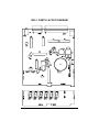
Take a look at the parts layout diagram, there is quite a lot to the construction
of the URC1. It's easier than it seems once you get going, and after you have
placed a few of the "landmark" components. Other part's positions are
referenced to them, and construction goes quite smoothly. This will help in
relating from one part to another what specific holes a part may require on
the board, and the part's orientation. In addition, we will discuss the purpose
of most components or groups of components as we go along.
Be sure to read through all the steps, and check the boxes as you go to be
sure you didn't miss any important steps. Most of the problems we find here
at the factory are due to faulty assembly - no matter how experienced the
builder may be - it's especially tough to tell a 30 year experienced Ham that
he goofed! Before you run the circuit, check all diodes and polarized
capacitors for proper orientation.
Tips and Notes:
Use a good soldering technique - let your soldering iron tip gently heat the
traces to which you are soldering, heat both wires and pads simultaneously.
Apply the solder on the iron and the pad when the pad is hot enough to melt
the solder. The finished joint should look like a drop of water on paper,
somewhat soaked in.
Parts are mounted on the top side of the board, which on this kit is the side
marked TOP.
IC sockets - A good practice, but not necessary in digital or low frequency
circuits such as this. This prevents the horror of desoldering a bad or
incorrectly placed IC.
Part orientation - All parts in the kit are mounted at 90 degree angles to each
other, meaning that all parts are either parallel or perpendicular to the board.
Part installation - when parts are installed, the part is placed flat to the board,
and the leads are bent on the backside of the board to prevent the part from
falling out before soldering. The part is then soldered securely to the board,
and the remaining lead length is clipped off. Some parts may have body paint
on their leads, preventing the solder from making a firm bond. In this case,
lightly scrape the paint away to allow the solder to make contact with the
wire.
URC1 • 6
RAMSEY URC1 PARTS LIST:
SEMICONDUCTORS
1 7805 5 volt power regulator (VR1)
1 145436 (or MC145436) 14 pin dip DTMF decoder IC (U5)
1 68HC705J2 20 pin dip pre-programmed microcontroller
(white sticker marked URC-1) (U6)
1 MAX7219 24 pin dip 8 digit display driver (U2)
1 MAX500 quad serial digital to analog converter (U7)
2 74HC595 serial latched shift registers (U1,U3)
1 DS1267 - 10 dual 10K digitally controlled potentiometer (U4)
6 seven segment LED displays (DSP1,2,3,4,5,6)
2 Red LEDs (D2,6)
2 1N4002 black epoxy diodes (D9, D10)
1 2N3904 NPN type transistor (Q2)
1 221-334-211 PNP or equivalent transistor (Q1)
CAPACITORS
5 .01uF disk ceramic capacitors (marked .01 or 103 or 10 nF)
(C2,5,7,10,11)
1 .1uF disk ceramic capacitor (marked .1 or 104) (C8)
1 470pF disk ceramic capacitor (marked 470 or 471) (C9)
1 100uF to 220uF electrolytic capacitor (C15)
3 10uF electrolytic capacitors (C4,6,13)
1 47uF electrolytic capacitor (C14)
RESISTORS
2 10K ohm (brown-black-orange) (R1,2)
4 47K ohm (yellow-violet-orange) (R4,5,6,7)
1 1M ohm (brown-black-green) (R3)
HARDWARE AND MISCELLANEOUS
1 3.579 Mhz crystal (Marked 3.579 or 3.579264) (X1)
1 1/8" PC mounted minijack (J1)
1 Power jack (J2)
1 Set hardware for regulator (1 screw and 1 nut)
1 34 pin right angle connector (CON1)
1 13 pin right angle connector (CON2)
1 3.9VDC lithium backup battery (B1)
1 Main PC board
1 Display PC board
1 20 Pin IC socket
1 4 inches of #24 bus wire
URC1 • 7
CONSTRUCTION OF THE URC1:
The first thing we will do with this kit is check all of our parts and pieces to
make sure we have them all. Use the parts list and your layout diagram to do
this. If there are any differences, make sure the schematic agrees with what
you have, and also be aware of the tolerances parts have in a kit. Non-critical
parts can vary quite a bit with almost no effect on kit operation. For example
you may get 1uF capacitors in place of 10uF capacitors, or a 3.579 crystal in
place of a 3.579545 crystal. No harm done as these will make no difference in
kit operation. Note there are two boards in this kit, as we will start with the
larger main board in our assembly. You may have to break apart the two
boards depending on how they are shipped.
1. Orient the circuit board as shown in the parts layout diagram.
2. Install J1, the PC mounted 1/8" minijack. This is where you hook up the
audio with the DTMF tones.
3. Install C14, a 47uF electrolytic capacitor. Electrolytic capacitors are
polarized and must be installed correctly. They are usually marked with a
black stripe and a ( - ) indicating their negative lead, while PC boards will
usually indicate the ( + ) hole.
At this point you may wish to make the decision of whether or not to use IC
sockets to mount your ICs. Though they will add to the cost of your kit, they will
prevent the horror of soldering in ICs the wrong direction, or the inability to
easily replace a bad IC yourself. If you are a confident good kit builder, you
wont have to worry about this.
4. Install U7, the 4 channel digital to analog converter (MAX 500, 16 dip).
Pay extra close attention to the orientation of this device and make sure it
is installed in the same direction as in the parts layout diagram. Notice the
part has a tab or dimple representing pin 1. Also note that most if not all of
these components are static sensitive so if you want to be cautious,
ground your body with a clip lead to a ground such as an oscilloscope
chassis. Make sure and practice good soldering skills, and keep an eye
out for solder bridges or cold joints as you go.
5. Install C6, a 10uF electrolytic capacitor. Make sure and check polarity
before soldering!
6. Install R4, a 47K resistor (yellow-violet-orange).
7. Install the 20 pin IC socket where U6 is to go, the microcontroller IC
with the sticker marked URC1. Gently insert the U6 into the socket noting
where pin 1 is. Pay close attention to the orientation of the tab on this part.
URC1 • 8
8. Install U4, the dual digitally controlled potentiometer (marked DS1267).
Pay close attention again to the orientation of this part. This part as you
will notice controls the position of the wiper on a 10K pot, and has very
good linearity.
9. Install U3, one of the 74HC595 serial shift registers. Each of these ICs
control eight on/off outputs, and can be cascaded for up to 64 outputs on
this kit. Check orientation.
10. Install U1, the other 74HC595 serial shift register. Again check the
orientation of this device.
11. Install C2, a .01uF ceramic capacitor (marked .01, 10nF or 103).
Notice that this type of capacitor has no polarity markings, and is not
critical in installation.
12. Install C13, a 10uF electrolytic capacitor. Pay close attention to it's
polarity unlike the ceramic capacitor.
13. Install C15, the larger 100uF to 220uF electrolytic capacitor. Check
it's polarity before soldering. Electrolytic capacitors, if installed incorrectly
have been known to operate poorly, get warm, and possibly even
explode, so take caution when using these capacitors!
14. Install D9, one of the 1N4002 diodes. These diodes are used to
"steer" the supply voltage to the microcontroller. During normal operation,
these diodes "steer" the voltage away from trying to recharge B1, and
during power down, they "steer" the battery towards the microcontroller,
and away from the other parts to save on power. Notice the white band on
the diode, this is the cathode end. Make sure it's in the same orientation
as the parts layout diagram shows.
15. Install D10, the other 1N4002 diode. Pay close orientation to the
orientation of the cathode (banded) end of the diode. These two diodes
that you just installed cause the microcontroller to go into power down
mode, thus preserving the memory so passwords and output options are
not lost.
16. Install Q1, a PNP type transistor marked 221-334-211. Note where
the lettering is, this is not the flat side, the side without the lettering is!
(You can tell since the larger flat side does not have the lettering.)
17. Install B1, the 3.9V lithium battery. Note the case of this battery is
positive, not ground and it fits in easily only one way.
18. Install R2, a 10K ohm resistor (brown-black-orange).
19. Install C8, a .1uF ceramic capacitor (marked .1 or 104). This causes
the microcontroller to reset properly on power up.
URC1 • 9
20. Install C9, a 470pF ceramic capacitor (marked 470 or 471).
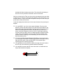
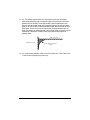
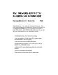
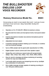
21. Install VR1, the 7805 regulator into the the three holes provided in the
board. The metallic portion of the regulator should face towards the tabbed
side of the board. Gently bend the regulator over until the hole in the tab
lines up with the hole in the PC board. Install the provided screw and nut
through the hole as shown, and tighten the nut until the regulator is snug to
the board. Then solder the three leads securely to the board.
22. Install C7, a .01uF ceramic capacitor (marked .01, 103 or 10nF).
23. Install X1, the 3.579Mhz crystal (silver can). Note that there are three
holes provided for this crystal since there are a couple of sizes of the metal
cans available. Note how it is placed in relation to the silk screen on the
board. Mount X1 as flush to the board as possible.
24. Install R3 a 1M ohm resistor (brown-black-green).
7805
Shiny side
Topside
PC Board
Nut
Screw
25. Install U5, the 145436 tone decoder IC (14 pin dip marked
MC145436). Make sure and double check it’s orientation before soldering.
Also check for soldering mistakes before continuing.
26. Install C4, a 10uF electrolytic capacitor. Check polarity!
27. Install C5, a .01uF ceramic capacitor (marked .01, 103, or 10nF).
28. Install C10, a .01uF ceramic capacitor (marked .01, 103, or 10nF).
29. Install C11, a .01uF ceramic capacitor (marked .01, 103, or 10nF).
30. Install R1, a 10K resistor (brown-black-orange).
31. Install U2, the MAX7219 display driver (marked MAX7219). Check
orientation and solder connections!
32. Install Q2, the NPN transistor marked 2N3904. Notice this time the
lettered side is the flat side. Be sure and orient it the same as on the silk
screen
33. Install R5, a 47K ohm resistor (yellow-violet-orange).
34. Install R6, another 47K ohm resistor (yellow-violet-orange).
35. Install R7, yet another 47K ohm resistor (yellow-violet-orange). The
two preceding transistors and these three resistors assist the URC1 in
URC1 • 10
shutting itself down during a power down. They then allow the battery to
take over memory retention of the data in the microcontroller.
Now here comes the fun! Take your time on the next stages as they can make
or break your kit. Don't be a bozo and rush assembly to get it done, hook it up,
and then destroy it. Play it smart and have patience and your kit will make you
proud when it works the first time!
Locate the display board and orient it in the same direction in the parts layout
diagram.
36. Install DSP1, one of the seven segment displays. Pay very close
attention to where the decimal point is in reference to the notches on the
board. Notice the decimal point faces the lower right of the board. This is
where the soldering becomes difficult, the pads are very close to the
traces, and solder bridges are easier to make. A small tipped soldering
iron with a clean tip (wipe it often on a damp sponge) is required for best
results. This is where patience really counts! Check and double check
orientation before soldering, since desoldering on these fine traces will
absolutely destroy them.
37. Hope you had a fun time doing the first display, now you get to do it
five more times! Install DSP2 - DSP6 using the same technique as above.
Start with DSP2 and in order end with DSP6. This prevents finger
squeezing and much ranting and raving.
38. Install D6 one of the red LEDs. Notice the longer of the two leads on
the LED, this is the lead that is installed towards the displays.
39. Install D2, the other red LED. Also notice that it is installed with the
longer lead towards the displays.
A
K
URC1 • 11
Locate the main board again and we will finish it up.
40. Install CON2, the thirteen pin connector. Insert it in the holes as
shown in the diagram, making sure that the leads point to the back of the
board.
41. Install CON1, the 34 pin connector using the same procedure as
before. This connector may consist of two pieces, one 20 pin and one 14
pin connector. If so, place them together on the board to make one 34 pin
connector. Check all of your solder joints on the two connectors before
proceeding. Remember that you are responsible for damage that occurs to
the output devices, so you don’t want to goof up!
C O N 1 &
M A IN
P C
2
B O A R D
Now here comes some more fun! First check over all of your connections on
the display board as well as the main board, you sure wouldn't want to come
this far to make a mistake! Now it's time to join the two boards together.
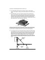
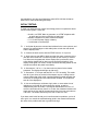
42. Notice the holes in the main board and the display board where JMPA and JMP-B are located. Cut the piece of thick bus wire in two. Using the
two pieces of bus wire, install the jumpers to hold the main board and the
display boards at 90 degree angles to each other. Notice how there are
notches in the main board and display board to assist in aligning them.
Use the notches to align the display board with the main board, note how
the display board is mounted with the displays facing away from the main
board.
Support
wire
Display
Solder
fillet
URC1 • 12
Main
board
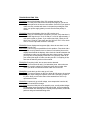
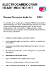
43. The display board mounts at a right angle to the main board with
solder pads providing both mechanical support and electrical connection
between the two boards. The display board is placed against the main
board so that the solder pads on the display board line up with the solder
pads on the main board. Solder the display board pads flush with the main
board pads. Check to be sure the two boards are perpendicular and not
tilted, then solder all remaining pads. Use enough solder to provide a good
mechanical connection, but don’t cause any solder bridges between
adjacent pads.
Main PC boar d
Dis play PC board
Solder f illet betw een PC
boar ds
44. A last minute addition: Install J2, the DC power jack. This is where the
7-15VDC will be applied upon power up.
URC1 • 13
Congratulations you have just finished the entire URC1 kit! Now all that we
have to do is some initial testing and setup.
INITIAL TESTING:
To begin our initial tests, we need a few missing pieces to complete the whole
remote control system. These are:
❍A
radio, or a DTMF dialer or generator, or a DTMF telephone with
an audio tap (see hints on building an audio tap).
❍ Suitable connectors for power, audio and outputs.
❍ A 7-15 volt DC power supply or battery.
❍ A multimeter or oscilloscope.
1. Verify that all parts are mounted and soldered in the correct places, and
there are no solder bridges or cold solder joints on both the main board
and the display board.
2. Connect the audio source with the DTMF tones to J1 of your kit.
3. Apply power to your URC1. Make sure that the center connector of the
jack you use is POSITIVE. On first time power up the memory is cleared
out, and so are the passwords. Also a display test is performed, so the
entire display should light for about one second before blanking. If the
display never lights or is erratic, consult the trouble shooting section of this
manual and unhook the power immediately.
4. Generate an “* M” or a * 6 on the touch tone phone for the master
password. The display should light up with zeros.
5. Generate a “*0” for oper and then 087 or “0TS” for testing. This mode
sets all of your timers on, and all of the outputs vary so a change can be
noticed. Notice that if this mode is performed during normal operation the
memories are changed and not restored when finished. This mode also
sets all of the displays on.
6. Use an oscilloscope, multimeter, logic probe, or some other form of
indication to verify that all of the outputs are varying, as well as
independently from each other. The outputs should switch from 0 to +5
volts, the levels should vary from 0 to +5 volts, the resistance between the
wiper and low or high side of the pots should vary from near zero ohms to
10K ohms. The timers should vary from near 5 volts to 0 volts.
If you have made it this far with your kit and have had no problems, you’re all
set to go! If not, consult the troubleshooting guide in the manual to determine
the cause of the problem and how to go about solving it.
URC1 • 14
TROUBLESHOOTING TIPS:
PROBLEM: None of the displays light, VR1 regulator gets hot fast.
SOLUTION: You likely have a short across the power supply or you have a
component placed in the incorrect orientation. Check all of your parts to
make sure they correlate with those in the parts layout diagram. Also
check your power supply polarity to make sure that the polarity is
correct.
PROBLEM: None of the displays light, but VR1 remains cool.
SOLUTION: Using an oscilloscope or a frequency counter, verify that there is
a 3.579 Mhz signal on pin 10 of U5 and pin 1 of U6 of approximately .5
volts peak to peak or greater. If you cannot check this, check pin 9 of
U6 for 4 to 5 volts DC. Also check pin 19 of U2 for 5 VDC. If not, check
VR1 for 5 volts output with at least 7 volts input.
PROBLEM: Some displays and segments light, others do not when I run all
eights into the unit.
SOLUTION: There is only two possibilities for this problem. First check with a
magnifier to verify that there are no shorts or cold solder joints on the
display board behind the displays. Also check the interface between the
two boards to make sure everything has been done correctly. Second,
you may have a faulty display. Since this is very unlikely, check all of
your solder joints again to make sure they are OK. If everything is fine,
then see the warranty section of the manual.
PROBLEM: Everything is OK, but no tones can be detected.
SOLUTION: Check around U4 and J1 for bad solder joints. Also make sure
that your crystal is marked 3.579 and not some other number. Also
check your audio connections and the audio level to the unit.
PROBLEM: Levels don’t go all the way up to 5 volts.
SOLUTION: This was necessary on the kit to allow all 256 steps to be noticed.
If a higher output voltage is required, remove D11 and put a jumper in
it’s place. Now you will notice that a value entered from 245 on up
represents full scale.
PROBLEM: Outputs only go to half voltage, some outputs don’t work at all,
resistance values don’t change.
SOLUTION: More than likely this is an assembly error, usually solder bridges
or cold solder joints surrounding CON1 and CON2. A fine tip soldering
iron and solder wick will help you to remedy these problems, as well as
patience and good troubleshooting skills.
URC1 • 15
PROBLEM: The thing just doesn't work! It must be the engineer's fault!
SOLUTION: We make absolutely sure that our products work beyond
expectations before the kits leave our doors. If you can't solve the
problem, send in the kit, if it's our fault the fix charge is free. Read the
warranty information in the back of the manual for more information.
USING YOUR URC1
There is so many things you can do with a kit of this nature, that we will only
go into some of the possibilities. Many more things can be done with it than
what is being shown, just use some of the basic principles shown here and
your imagination and you will be churning out the projects that will even
impress the experts!
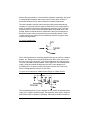
Connecting a relay to a switched output:
Once connected to the relay, the URC1 can turn a number of devices on and
off, such as home security systems, lights, answering machine, lawn watering
system, swimming pool filters, etc. Be sure the coil on the relay has a
resistance of no less than 100 ohms to be safe. If it is less, use a transistor
with a higher power dissipation rating.
Using a Level output as an isolated Variable Resistor:
This is a simple, yet useful way of isolating the URC1 from the unit being
controlled. This setup will work well for any circuit (within current limits) that
requires a variable resistance. For example this can be used to control a form
of squelch on a radio called level detection. This simple circuit can be used in
URC1 • 16
place of the pot presently in a circuit with this method of squelching. Also good
in voltage divider networks, and current controls. Notice other versions of
these opto-isolators can be used to isolate the switched outputs also.
The other method of squelch control uses the quieting phenomena during
reception of a signal to open the squelch. When there is not a signal there is
plenty of random noise received, especially high frequency noise. This high
frequency noise is used to close the squelch when the quieting effect is not
present. With this method all that is needed is the three pot connections on
the URC1 in place of the pot that previously controlled the squelch. These
variable pots can also replace the level detection method by tying the wiper
output to the high output.
To use the variable pots:
This is the simplest way of controlling signal levels such as volumes, voltages,
powers, etc. Always tie the common ground of the URC1 to the common on
the unit you are trying to control. If you are worried about the common on the
unit to be controlled not being isolated, run the URC1 off of an isolated power
supply. Using this method should protect the URC1 from damage from
grounding errors. L0 does not have to be tied to common, but must not go
lower in voltage than the common of your URC1.
To use a Level Output as a Variable Power Supply or Voltage Source:
This configuration allows a user to adjust a 12VDC-18VDC unregulated power
supply to a 0-10VDC regulated supply. The regulation in this case is limited to
how well the URC1’s regulator is operating. Parts can be modified in value to
URC1 • 17
change voltage output levels as well as current ratings. Note with larger
currents that you should provide a heat sink on Q1. To change the maximum
voltage output, use the formula:
Vout =5*(1 + R2/R1)
There are plenty of ways to use the outputs of the URC1 to control different
circuits, devices, and run equipment. These basic ideas given will get you
started on developing your own remote control system. If you want more ideas
or more detail on how to hook up these circuits, consult some of the
electronics magazines available at the supermarket, or go to your local library.
These sources are usually loaded with great ideas for interfacing the types of
output provided here with the external world!
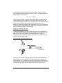
Building a Telephone Audio Tap:
Through this method the user can tap the DTMF tone off of a telephone line.
This is the simplest of methods to interface the URC1 to the telephone lines.
Notice though you will need some sort of answering device such as a
message machine to pick up the phone. If the phone is not off the hook, this
circuit will not pick up any audio.
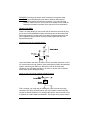
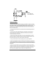
Inserting Audio output into the phone line:
To J1 Tone in
This is how you are able to insert the confirmation tones into the telephone
line so that when you are dialing from a remote location you can hear the
URC1 talk back to you, and let you know that a code was correctly received
and processed. You may also receive tones as well with this circuit. Notice it is
in parallel with the phone line instead of series like the previous circuit.
URC1 • 18
From confirm out
From CON1 pin 33
Setting up the URC1:
These are some general ideas for setting up the URC1 for either a multiple
user remote control, or a protected mode of operation. We will start from very
first power up, all the way to leaving the URC1 to do it’s stuff. If you are
interested in more details about the codes used refer to the the section on
URC1 command codes.
1. Power up and test the URC1 as instructed in the initial testing section of
the manual.
2. Hook up any of the peripherals that you may want to control such as
lamps, radios, alarm systems etc. Make sure commons on circuits are
connected properly to the URC1.
3. Enter in as a master user using *6. Use your tone generator to set the
devices you want to exclude from the user, such as the alarm system. Use
the control codes in the rear of the manual for instructions.
4. Set your initial values, check everything out for proper operation.
5. Set the user password, which is limited to three characters, and then the
master password which is limited to four. Make sure and write these down. If
you forget them, you have to disconnect the power and remove the battery to
reset them.
6. Press *3 to tell the URC-1 that you are finished. At this point the URC-1
will blank it’s display, and wait for the password of a user or master to access
it again. If a user is to access it, the items that you disabled by excluding
them cannot be changed. Only the master can change them now.
URC1 • 19
Charts and Diagrams:
Display Conventions:
0
1
2
3
4
5
6
7
8
9
A
B
C
D
#
*
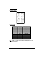
Pinouts of CON2:
Pin #
1
2
3
5
6
7
8
9
10
11
12
13
14
Name
GND
GND
LDS
CLK
GND
DATA
GND
LDP
GND
COUT
QH’
+5V
+5V
Description
Ground
Ground
Load Shift Registers
Serial Clock
Ground
Serial Data
Ground
Load Pots
Ground
Pots Serial Out
Shift Registers Out
+5V
+5V
Note: This jack is not used unless you plan on expanding your kit for more
control pots and outputs.
URC1 • 20
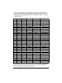
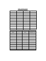
This is a table showing the signal available at each pin of CON1, the access
number for which the pin is accessed and changed, the group number for
disabling and enabling, description, name, and range of output. “?” indicates
a variable number.
Pin #
1
2
3
4
5
6
7
8
9
10
11
12
13
14
15
16
17
18
19
20
21
22
23
24
25
26
27
28
29
30
31
32
33
34
Name
VoutD
VoutA
VoutC
VoutB
+5V
+12V
GND
T2
T0
T1
W1
H1
L1
L0
H0
W0
GND
1,7
0,7
1,6
0,6
1,5
0,5
1,4
0,4
1,3
0,3
1,2
0,2
1,1
0,1
1,0
Tone
GND
Device #
15
12
14
13
18
16
17
9
9
9
8
8
8
1
0
1
0
1
0
1
0
1
0
1
0
1
0
1
-
Description
Level 3
Level 0
Level 2
Level 1
V source
V source
Common
Timer 2
Timer 0
Timer 1
Pot 1 Wiper
Pot 1 High
Pot 1 Low
Pot 0 Low
Pot 0 High
Pot 0 Wiper
Common
Output
Output
Output
Output
Output
Output
Output
Output
Output
Output
Output
Output
Output
Output
Output
Tone out
Common
Access #
*53???
*50???
*52???
*51???
*T2??*??*
*T0??*??*
*T1??*??*
*21???
Not adjusted
Not adjusted
Not adjusted
Not adjusted
*20???
*617?
*607?
*616?
*606?
*615?
*605?
*614?
*604?
*613?
*603?
*612?
*602?
*611?
*601?
*610?
*600?
-
Range
0-5V, 256 steps
0-5V, 256 steps
0-5V, 256 steps
0-5V, 256 steps
5V
12V
0V
10mS to 40H
10mS to 40H
10mS to 40H
0-10K, 256 steps
0-10K, 256 steps
0-10K, 256 steps
0-10K, 256 steps
0-10K, 256 steps
0-10K, 256 steps
0V
5V on off
5V on off
5V on off
5V on off
5V on off
5V on off
5V on off
5V on off
5V on off
5V on off
5V on off
5V on off
5V on off
5V on off
5V on off
Confirm Out
0V
Note: Pin 33 can be accessed as an output, but its value will change every time
a code is received and a tone is sent, therefore it is not recommended to be
used as an output other than for generating tones.
URC1 • 21
URC1 Control Codes:
The codes on the URC1 are very simple to use as well as comprehensive.
Codes have been laid out so that the letters on a touch tone phone represent
the action that you desire. Note that all codes begin with an asterisk. This was
done to prevent the normal dialing of a phone or some other device from
accessing the unit.
[ ] indicates not required or variable length.
{ } indicates one character
To access the URC1:
For master access:
*M[Password]* or *6[Password]*
Where master password length is at most 4 characters.
This code replies with two long tones indicating “M”
For user access:
*U[Password]* or *8[Password]*
Where user password length is at most 3 characters.
This code replies with two shorts and a Long to indicate “U”
Ex:
*M123*
Note that if no password has been set for either, the last asterisk is left off.
To set the password:
To set the master password:
*PM[Password]* or *76[Password]*
Where maximum password length is 4 characters. Entering no characters for
password disables the password.
This code replies with a short then long tone to indicate “A” for acknowledge.
To set the user password:
*PU[Password]* or *78[Password]*
Where maximum password length is 3 characters. Entering no characters for
password disables the password.
This code replies with a short then long tone to indicate “A” for acknowledge.
Note that you must be entered as a master to change these.
To set an output on or off:
To turn an output on:
*0{output set #}{Output #}1 or *6{output set #}{Output #}1
This code replies with a short then long tone to indicate “A” for acknowledge.
URC1 • 22
To turn an output off:
*0{output set #}{Output #}0 or *6{output set #}{Output #}0
This code replies with a short then long tone to indicate “A” for acknowledge.
Note that the last one or zero denotes on and off respectfully. Note there is
only eight output sets (0-7) and eight outputs per set (0-7). Any number
entered over seven causes an error and the command is aborted. Also note
that output 0,0 is used as a confirm tone output. In other words don’t use it as
an output unless it is to generate a tone.
To set a Level:
To set directly:
*L{Level #}[0-255] or *5{Level #}[0-255]
Using this method you can quickly set any level you desire. For example if you
want 2.5 volts out, enter 127 for the level, and if you want the full 5 volts enter
255. Three numbers must be entered for the level.
This code replies with a short then long tone to indicate “A” for acknowledge.
1/4 scale example on level output 0:
*50064
Where 5 is the command code, 0 is the device code, and 064 is the value.
To vary the level down:
*L{Level #}* or *5{Level #}*
Press and hold the last asterisk to keep decreasing the level. The level stops
decreasing at a value of zero. When it has reached zero, the URC1 replies
with a short then long tone to indicate “A” for acknowledge.
To vary the level up:
*L{Level #}# or *5{Level #}#
Press and hold the pound sign to keep increasing the level. The level stops at
a value of 255. When it has reached 255, the URC1 replies with a short then
long tone to indicate “A” for acknowledge.
Note that there is only four level outputs (0-3), so any value over 3 will cause
an error and the command will be aborted. Also any value over 255 in the
level code will do the same.
To set a Control Pot:
This method is almost identical to setting the levels except for the command
code.
To set directly:
*C{Level #}[0-255] or *2{Level #}[0-255]
Using this method you can quickly set any resistance you desire. For example
if you want 5K ohms at the wiper, enter 127 for the resistance, and if you want
the full 10K ohms, enter 255. Three numbers must be entered for the level.
The URC1 replies with a short then long tone to indicate “A” for acknowledge.
3/4 scale example on resistor 1:
*21192
URC1 • 23
Where 2 is the command code, 1 is the device code, and 192 is the value.
To vary the resistance down:
*C{Level #}* or *2{Level #}*
Press and hold the last asterisk to keep decreasing the resistance. The
resistance stops decreasing at a value of zero (near zero ohms).
The URC1 replies with a short then long tone when at zero to indicate “A” for
acknowledge.
To vary the resistance up:
*C{Level #}# or *2{Level #}#
Press and hold the pound sign to keep increasing the resistance. The
resistance stops at a value of 255 (10K ohms). The URC1 replies with a short
then long tone at a value of 255 to indicate “A” for acknowledge.
Note that there are only four pot controls (0-3) possible, though only two
provided on this kit, so any value over 3 will cause an error and the command
will be aborted. Also any value over 255 in the pot value code will do the
same.
To set a Timer:
*T{Timer #}tt[*][ss][*][mm][*][hh] tt[*][ss][*][mm][*][hh] or
*8{Timer #}tt[*][ss][*][mm][*][hh] tt[*][ss][*][mm][*][hh]
(.........Time off.......) (.........Time on.........)
tt indicates hundredths of a second, ss indicates seconds, mm indicates
minutes, and hh indicates hours. Where Timer # is 0-2; tt, ss, mm, and hh are
values from 00-99. Any value over these will cause an error and the command
will be aborted. Notice that pressing an asterisk at the end of tt, ss, or mm will
end the command for that part of the timing cycle. For example pressing:
*8201*01*
will set timer 2 on for 10mS and off for 10mS. To set on and off for 1 hour
press:
*820000000100000001
Note there are no asterisks at the end of each time. This makes entering
easier since all of the times are entered anyhow. The only time you need to
press the ending asterisk is when you plan on not entering the hours.
After each time is set, the URC1 replies with a short then long tone to indicate
“A” for acknowledge. When you are done entering the URC1 replies with a
short then long tone to indicate “A” for acknowledge so that two “A”s are sent
upon completion. Try it out to see how it works
Some more examples:
To set timer2 on for 120mS and off for 12 hours, 35 minutes:
*820000351212*
URC1 • 24
To set timer1 on for 35 hours 12seconds, and off fore 10mS:
*8101*00120035
Hook up some LEDs as shown with series resistors to the timer outputs, and
then experiment a bit to see how this method works. Have patience as these
codes take a little time to get used to.
For the master user to exclude devices from the user:
To exclude:
*X[00-18]1
To include:
*X[00-18]0
The access number is found on the chart with the pinouts of CON1. Since
there is only 19 devices (0-18), any number over 18 is rejected and the
command is aborted.
The URC1 replies with a short then long tone to indicate “A” for acknowledge.
Example to turn timer 2 off from the user:
*9181
Where 9 is the control code, 18 is the device number, and 1 disables the
device from the user changing it. Notice of course that you must be entered as
a master user to change these settings. Entering a 1 disables, and a 0
enables.
Special codes:
Resetting the entire unit:
Reset the display only:
*0000
Clear all:
*0CAL or *0252
URC1 • 25
Note that this command can be dangerous as it clears out everything,
passwords as well as output settings. This command will only work if you’re
entered as a master user.
The URC1 replies with a short then long tone to indicate “A” for acknowledge.
Testing the URC1:
*00TS or *0087
This command is also dangerous, but it does not destroy the passwords. It
only alters the outputs. This command is only meant to be used for testing and
identification of problems. This code is only available to the master user.
The URC1 replies with a short then long tone to indicate “A” for acknowledge
and then begins testing.
Done Accessing the URC1:
*D or *3
This command blanks out the display to save on power, and exits the user
mode. The URC1 then waits for the next valid password to light the displays
and begin work again.
The URC1 replies with two longs then a short tone to indicate “G” for goodbye.
Other tones:
The URC1 will return a long then short tone to indicate an error in entry such
as password protected, numbers that are too large, and accidental keystrokes
during entry of a code. Otherwise the URC1 just ignores you if there is no
valid code entered.
URC1 • 26
Notes and Passwords:
Password
Master/User
Date
URC #
1234
M
6-5-94
1
Device Name
User Mask #
Code for Access
Notes
Lamp
0
*601?
? indicates 1 or 0
URC1 • 27
Connector considerations :
Upon design of this kit we determined that we would use standard
size connectors for interface. We ended up using connector cables from PCs
to determine what sizes you may have laying around at home, or available at
the local electronics store. Connector 1 uses a 34 pin connector, which is
common on most hard drives, and connector 2 uses a 14 pin connector which
was a common size in the stores near here.
To connect these up you can bring the wires of the ribbon cable out to
a connector board that you devise yourself, or add on some wire to run
directly to the device you wish to control. Use the look up tables on pages 20
and 21 to determine what wires go where. Note that pin 1 and wire one are
marked so that you don’t get confused.
Expanding Notes:
If you decide to expand your URC1 to take full advantage of the
number of outputs it may control, notice how almost all of the chips in this kit
are serially accessed. They all work in much the same way as a serial latching
shift register, so all that needs to be done is to cascade the devices. (We will
leave this up to you to figure out and experiment with). Note that U1 and U3
are already in the cascaded form (you can use their example to expand the
number of outputs). If you don’t feel too confident in doing it yourself, we will
be coming out with an expansion kit in the near future.
URC1 • 28
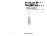
URC-1 PARTS LAYOUT DIAGRAM
URC1 • 29
The Ramsey Kit Warranty
Please read carefully BEFORE calling or writing in about your kit. Most problems can be
solved without contacting the factory.
Notice that this is not a "fine print" warranty. We want you to understand your rights and ours to! All
Ramsey kits will work if assembled properly. The very fact that your kit includes this new manual is your
assurance that a team of knowledgeable people have field-tested several "copies" of this kit straight
from the Ramsey Inventory. If you need help, please read through your manual carefully, all information
required to properly build and test your kit is contained within the pages!
1. DEFECTIVE PARTS: It's always easy to blame a part for a problem in your kit, Before you conclude
that a part may be bad, thoroughly check your work. Today's semiconductors and passive components
have reached incredibly high reliability levels, and its sad to say that our human construction skills have
not! But on rare occasion a sour component can slip through. All our kit parts carry the Ramsey
Electronics Warranty that they are free from defects for a full ninety (90) days from the date of
purchase. Defective parts will be replaced promptly at our expense. If you suspect any part to be
defective, please mail it to our factory for testing and replacement. Please send only the defective part
(s), not the entire kit. The part(s) MUST be returned to us in suitable condition for testing. Please be
aware that testing can usually determine if the part was truly defective or damaged by assembly or
usage. Don't be afraid of telling us that you 'blew-it', we're all human and in most cases, replacement
parts are very reasonably priced.
2. MISSING PARTS: Before assuming a part value is incorrect, check the parts listing carefully to see if
it is a critical value such as a specific coil or IC, or whether a RANGE of values is suitable (such as "100
to 500 uF"). Often times, common sense will solve a mysterious missing part problem. If you're missing
five 10K ohm resistors and received five extra 1K resistors, you can pretty much be assured that the '1K
ohm' resistors are actually the 'missing' 10 K parts ("Hum-m-m, I guess the 'red' band really does look
orange!") Ramsey Electronics project kits are packed with pride in the USA. If you believe we packed
an incorrect part or omitted a part clearly indicated in your assembly manual as supplied with the basic
kit by Ramsey, please write or call us with information on the part you need and proof of kit purchase
3. FACTORY REPAIR OF ASSEMBLED KITS:
To qualify for Ramsey Electronics factory repair, kits MUST:
1. NOT be assembled with acid core solder or flux.
2. NOT be modified in any manner.
3. BE returned in fully-assembled form, not partially assembled.
4. BE accompanied by the proper repair fee. No repair will be undertaken until we have received the
MINIMUM repair fee (1/2 hour labor) of $18.00, or authorization to charge it to your credit card
account.
5. INCLUDE a description of the problem and legible return address. DO NOT send a separate letter;
include all correspondence with the unit. Please do not include your own hardware such as
non-Ramsey cabinets, knobs, cables, external battery packs and the like. Ramsey Electronics,
Inc., reserves the right to refuse repair on ANY item in which we find excessive problems or
damage due to construction methods. To assist customers in such situations, Ramsey
Electronics, Inc., reserves the right to solve their needs on a case-by-case basis.
The repair is $36.00 per hour, regardless of the cost of the kit. Please understand that our technicians
are not volunteers and that set-up, testing, diagnosis, repair and repacking and paperwork can take
nearly an hour of paid employee time on even a simple kit. Of course, if we find that a part was
defective in manufacture, there will be no charge to repair your kit (But please realize that our
technicians know the difference between a defective part and parts burned out or damaged through
improper use or assembly).
4. REFUNDS: You are given ten (10) days to examine our products. If you are not satisfied, you may
return your unassembled kit with all the parts and instructions and proof of purchase to the factory for a
full refund. The return package should be packed securely. Insurance is recommended. Please do not
cause needless delays, read all information carefully.
URC1 • 30
URC1 UNIVERSAL REMOTE CONTROL
Quick Reference Page Guide
Introduction to the URC1...................................... 4
Parts list ............................................................... 7
URC1 Assembly instructions ................................ 8
Initial testing ......................................................... 14
Troubleshooting tips............................................. 15
Setup ................................................................... 19
Notes and passwords .......................................... 27
Connector Considerations.................................... 28
Schematic diagram .............................................. 29
Parts Layout diagram ........................................... 30
Ramsey kit warranty ............................................ 31
REQUIRED TOOLS
• Soldering Iron (Radio Shack #RS64-2072)
• Thin Rosin Core Solder (RS64-025)
• Needle Nose Pliers (RS64-1844)
• Small Diagonal Cutters (RS64-1845)
• <OR> Complete Soldering Tool Set
(RS64-2801)
TOTAL SOLDER POINTS
324
ESTIMATED ASSEMBLY
TIME
Beginner .............. 8.5 hrs
Intermediate......... 5.5 hrs
Advanced ............. 4.0 hrs
ADDITIONAL SUGGESTED ITEMS
• Soldering Iron Holder/Cleaner (RS64-2078)
• Holder for PC Board/Parts (RS64-2094)
• Desoldering Braid (RS-2090)
Price: $5.00
Ramsey Publication No. MURC1
Assembly and Instruction manual for:
RAMSEY MODEL NO. URC1 UNIVERSAL
REMOTE CONTROL KIT
RAMSEY ELECTRONICS, INC.
793 Canning Parkway
Victor, New York 14564
Phone (716) 924-4560
URC1 • 31
Fax (716) 924-4555
www.ramseykits.com
Printed on recycled paper