1
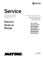
Service
This manual is to be used by qualified appliance
technicians only. Maytag does not assume any
responsibility for property damage or personal
injury for improper service procedures done by
an unqualified person.
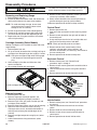
This Base Manual covers general information
Refer to individual Technical Sheet
for information on specific models
This manual includes, but is
not limited to the following:
Electric
Slide-In
Range
JES8750AAB/W
JES8850AAB/Q/S/W
JES8850ACB/S/W
JES9750AAB/S/W
JES9750ACB/W
JES9800AAB/Q/S/W
JES9800ACB/S/W
JES9860AAB/S/W
JES9860ACB/S/W
16025927
February 2005
©2005 Maytag Services
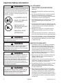
Important Information
Pride and workmanship go into every product to provide our customers with quality products. It is possible, however,
that during its lifetime a product may require service. Products should be serviced only by a qualified service
technician who is familiar with the safety procedures required in the repair and who is equipped with the proper tools,
parts, testing instruments and the appropriate service information. THE TECHNICIAN IS RESPONSIBLE TO
REVIEW ALL APPROPRIATE SERVICE INFORMATION BEFORE BEGINNING REPAIRS.
Important Notices for Servicers and Consumers
!
WARNING
To avoid risk of severe personal injury or death, disconnect power before working/servicing on appliance to avoid
electrical shock.
To locate an authorized servicer, please consult your telephone book or the dealer from whom you purchased this
product. For further assistance, please contact:
Customer Service Support Center
CAIR Center
Web Site
Telephone Number
WWW.JENNAIR.COM ............................................. 1-800-536-6247
CAIR Center in Canada .......................................... 1-800-688-2002
Recognize Safety Symbols, Words, and Labels
! DANGER
DANGER—Immediate hazards which WILL result in severe personal injury or death.
!
WARNING
WARNING—Hazards or unsafe practices which COULD result in severe personal injury or death.
!
CAUTION
CAUTION—Hazards or unsafe practices which COULD result in minor personal injury, product or property
damage.
2
16025927
©2005 Maytag Services
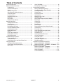
Table of Contents
Important Information ................................................... 2
Important Safety Information
All Appliances .......................................................... 4
Surface Cooking Units ............................................. 4
Ovens ....................................................................... 5
Self-Cleaning Ovens ................................................ 5
Glass/Ceramic Cooking Surfaces ............................ 5
Ventilation Hoods ..................................................... 5
In Case of Fire ......................................................... 5
Surface Element Fire ............................................... 5
Oven Fires ............................................................... 5
Precautions ............................................................. 5
Product Safety Devices ........................................... 6
General Information
Cooking Nomenclature ............................................. 7
Specifications .......................................................... 8
Placement of the Oven ............................................. 8
Do Not Block Air Vents ............................................ 8
Location of Model Number ........................................ 8
Grounding Instructions ............................................. 8
Model Identification .................................................. 8
Service ..................................................................... 8
Parts and Accessories ............................................. 8
Extended Service Plan ............................................. 8
Range Description ................................................... 9
Troubleshooting Procedures
Troubleshooting Chart ............................................ 10
Fault Code Chart .................................................... 11
Oven Sensor Chart and Meat Probe Chart ............ 11
Testing Procedures
Component Testing Procedures ............................. 12
Oven Control Testing Procedures .......................... 15
Relay Logic ............................................................ 17
©2005 Maytag Services
Quick Test Mode .................................................... 18
Description of Fault Codes .................................... 19
Disassembly Procedures
Moving and Replacing Range ................................ 20
Cartridge Assembly (Select Models) ...................... 20
Maintop Assembly .................................................. 20
Control Panel ......................................................... 20
Electronic Control .................................................. 20
Infinite Switch ........................................................ 20
Bottom Access Panel ............................................. 21
Indicator Lights ...................................................... 21
Meat Probe Receptacle (Select Models ................. 21
Back Panel ............................................................ 21
Cooling Fan ........................................................... 21
Transformer ........................................................... 21
Bake Element ......................................................... 21
Broil Element .......................................................... 21
Downdraft Blower Motor (Select Models) ............... 21
Oven Sensor .......................................................... 22
Front Side Trim ...................................................... 22
Oven Light Bulb/Oven Light Socket ........................ 22
Oven Light Switch .................................................. 22
Convection Fan ...................................................... 22
Oven Vent/Smoke Eliminator .................................. 22
Hi-Limit Thermostat ................................................ 22
Oven Door Latch .................................................... 23
Oven Door Removal ............................................... 23
Oven Door Hinge Receiver .................................... 23
Door Disassembly .................................................. 24
Appendix A: Installation Instructions
Models JES8750AA*, JES8850A** ...................... A-2
Models JES9750A**, JES9800A**, JES9860A**. A-8
Appendix B: Use Information
Models JES8750AA*, JES8850A** ...................... B-2
Models JES9750A**, JES9860A** ....................... B-6
Model JES9800A** ............................................. B-11
Care and Cleaning .............................................. B-14
16025927
3
Important Safety Information
!
ALL APPLIANCES
WARNING
To reduce the risk of the appliance tipping, it must be
secured by a properly installed anti-tip bracket(s). To
make sure bracket has been installed properly, remove
the storage drawer and look under the range with a
flashlight. Bracket(s) must be engaged in the rear
corner of the range.
• ALL RANGES CAN TIP
• INJURY TO PERSONS
COULD RESULT
4. Wear Appropriate Apparel—Loose fitting or hanging
garments should never be worn while using
appliance.
5. User Servicing—Do not repair or replace any part of
the appliance unless specifically recommended in the
manual. All other servicing should be referred to a
qualified technician.
6. Storage in or on Appliance—Flammable materials
should not be stored in an oven or near surface
units.
• SEE INSTALLATION
INSTRUCTIONS
7. Do Not Use Water on Grease Fires—Smother fire or
flame, or use dry chemical or foam-type extinguisher.
WARNING
To avoid personal injury, do not sit, stand or lean on
oven door or oven drawer.
!
WARNING
This appliance contains or produces a chemical or
chemicals which can cause death or serious illness
and which are known to the state of California to
cause cancer, birth defects or other reproductive
harm. To reduce the risk from substances in the fuel or
from fuel combustion make sure this appliance is
installed, operated, and maintained according to the
instructions in this booklet.
!
WARNING
To avoid risk of electrical shock, property damage,
personal injury, or death, verify wiring is correct, if
components were replaced. Verify proper and
complete operation of unit after servicing.
4
8. Use Only Dry Potholders—Moist or damp potholders
on hot surfaces may result in burns from steam. Do
not let potholder touch elements. Do not use a towel
or other bulky cloth.
SURFACE COOKING UNITS
WARNING
To avoid risk of electrical shock, personal injury, or
death, make sure your range has been properly
grounded and always disconnect it from main power
supply before any servicing.
!
2. Never Use Your Appliance for Warming or Heating
the Room.
3. Do Not Leave Children Alone—Children should not
be alone or unattended in the area where the
appliance is in use. They should never be allowed to
sit or stand on any part of the appliance.
• INSTALL ANTI-TIP
BRACKET(S) PACKED
WITH RANGE
!
1. Proper Installation—Be sure your appliance is
properly installed and grounded by a qualified
technician.
1. Use Proper Pan Size—This appliance is equipped
with one or more surface units of different size.
Select utensils having flat bottoms large enough to
cover the surface unit heating element. The use of
undersized utensils will expose a portion of the
heating element to direct contact and may result in
ignition of clothing. Proper relationship of utensil to
burner will also improve efficiency.
2. Never Leave Surface Units Unattended at High Heat
Settings—Boilover causes smoking and greasy
spillovers that may ignite.
3. Protective Liners—Do not use aluminum foil to line
oven bottom. Improper installation of these liners may
result in a risk of electrical shock or fire.
4. Glazed Cooking Utensils—Do not use glass, ceramic,
earthware, or other glazed utensils. They can
damage smoothtop and can break due to sudden
change in temperature.
5. Utensil Handles Should be Turned Inward and Not
Extend Over Adjacent Surface Units—To reduce the
risk of burns, ignition of flammable materials, and
spillage due to unintentional contact with the utensil,
the handle of a utensil should be positioned so that it
is turned inward, and does not extend over adjacent
surface units.
16025927
©2005 Maytag Services
Important Safety Information
OVENS
In Case of Fire
1. Use Care When Opening Door—Let hot air or steam
escape before removing or replacing food.
Fires can occur as a result of over cooking or excessive
grease. Though a fire is unlikely, if one occurs, proceed
as follows:
2. Do Not Heat Unopened Food Containers—Buildup of
pressure may cause container to burst and result in
injury.
3. Keep Oven Vent Ducts Unobstructed.
4. Placement of Oven Racks—Always place oven racks
in desired location while oven is cool. If rack is
removed while oven is hot, do not let potholder
contact hot heating element in oven.
SELF-CLEANING OVENS
Surface Element Fire
1. Smother the fire with a nonflammable lid or baking
soda, or use a Class ABC or BC extinguisher. Not
water. Not salt. Not flour.
2. As soon as it is safe to do so, turn the surface
controls to “OFF”.
Oven Fires
1. Do Not Clean Door Gasket—The door gasket is
essential for a good seal. Care should be taken not to
rub, damage, or move the gasket.
2. Do Not Use Oven Cleaners—No commercial oven
cleaner or oven liner protective coating of any kind
should be used in or around any part of the liner.
1. If you see smoke from your oven, do not open oven
door.
2. Turn oven control to “OFF”.
3. As an added precaution, turn off power at main
circuit breaker or fuse box.
3. Clean Only Parts Listed in Manual.
4. Turn on vent to remove smoke.
4. Before Self-Cleaning the Oven—Remove broiler pan,
oven racks, and other utensils.
5. Allow food or grease to burn itself out in oven. Do not
open oven door.
5. Remove all items from range top and backguard.
6. If smoke and fire persist, call fire department.
7. If there is any damage to components, call an
authorized servicer before using range.
GLASS/CERAMIC COOKING SURFACES
1. Do Not Cook on Broken Cooktop—If cooktop should
break, cleaning solutions and spillovers may
penetrate the broken cooktop and create a risk of
electrical shock. Contact a qualified technician
immediately.
2. Clean Cooktop With Caution—If a wet sponge or
cloth is used to wipe spills on a hot cooking area, be
careful to avoid a steam burn. Some cleaners can
produce noxious fumes if applied to a hot surface.
VENTILATION HOODS
1. Clean Ventilation Hoods Frequently—Grease should
not be allowed to accumulate on hood or filter.
2. When flaming foods under hood, turn fan off. The
fan, if operating, may spread the flame.
©2005 Maytag Services
Precautions
• Do not cook food directly on range top surface,
always use cookware.
• Do not mix household cleaning products. Chemical
mixtures may interact with objectionable or even
hazardous results.
• Do not put plastic items on warm cooking areas. They
may stick and melt.
• Do not slide rough objects across range top surface.
Scratching or metal marking can result.
• Do not use cookware with rough bottoms. They may
scratch smoothtop surface. Glass and ceramic
cookware should not be used.
• Do not use damp sponge or dishcloth to clean range
top. A film of soil-laden detergent water may collect on
range top. If this should happen, Amana Cleaning
Conditioning Cream removes this type of stain.
• Do not leave fat heating unless you remain nearby. Fat
can ignite if overheated by spilling onto hot surfaces.
• Do not allow pots to boil dry as this can cause damage
to cooking surface and pan.
• Do not use range top surface as a cutting board.
• Do not use range for storage or as a display counter.
16025927
5
Important Safety Information
Product Safety Devices
Safety devices and features have been engineered into
the product to protect consumer and servicer. Safety
devices must never be removed, bypassed, or altered in
such a manner as to defeat the purpose for which they
were intended.
Grounded Oven Frame
Ground prong on power
cord is connected to the
frame, usually a green
lead fastened by a
screw. Any part or
component capable of
conducting an electric
current is grounded by
its mounting.
If any ground wire,
screw, strap, nut, etc. is
removed for service, it
must be reconnected to
its original position with
original fastener before
the range is put into
operation. Failure to do
so can create a possible
shock hazard.
6
16025927
©2005 Maytag Services
General Information
This manual provides basic instructions and suggestions
for handling, installing and servicing electric ranges.
The directions, information, and warnings in this manual
are developed from experience and careful testing of the
product. If the unit is installed according to this manual, it
will operate properly and will require minimal servicing. A
unit in proper operating order ensures the consumer all
the benefits provided by clean, modern electric cooking.
This manual contains information needed by authorized
service technicians to install and service electric ranges.
There may be, however, some parts which need further
explanation. Refer to the Installation Instructions, Use
and Care, Technical Sheets or the toll-free technical
support line.
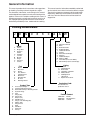
Cooking Nomenclature
J
E
S
9
8
6
0
A
A
W
Color
A
B
C
H
L
P
Q
S
T
W
F
N
Brand
A
C
G
Amana
Magic Chef
Graffer &
Sattler
Hardwick
Jenn-Air
Maytag
Norge
Universal
Crosley
H
J
M
N
U
Y
Listing
Fuel
B
D
E/J
G
L
M
P
X
W
Almond on Almond
Black
Brushed Chrome
Traditional White
Traditional Almond
Prostyle
Monochromatic Bisque
Stainless
Traditional Bisque
White on White
Frost White (True Color White)
Natural Bisque (True Color Bisque)
A
C
D
G
M
P
Butane
Dual Fuel
Electric
Gas, Natural
Liquid Propane
Microwave
Standing Pilot
No Fuel
Warming Drawer
X
UL/AGA
CSA/CGA/CUL
Dual Listed
220-240 V / 50-60 Hz
Military Model
PSB Approved
(Singapore)
Export 120 V / 60 Hz
Production Code
This identifies the
production version.
Product Type
A
C
D
E
G
L
M
P
Q
R
S
T
V
W
Y
Z
Accessory/Cartridge
Cooktop Updraft/Countertop
Downdraft Cooktop or Warming Drawer
Eyelevel Range
Grill
Range (20")
Range (36")
Drop In (24")
Wall Oven (27")
Range, Free-Standing (30")
Slide-In (30")
Range Hood
OTR
Wall Oven
RV Range
RV Top
©2005 Maytag Services
Feature Content
1000-3999
4000-6999
7000-9999
16025927
Brands
Maytag/Amana
Jenn Air
7
General Information
Specifications
Refer to individual Technical Sheet for specification
information.
Placement of the Oven
This freestanding range must be placed in the kitchen or
comparable room. All safety guidelines must be followed
(see Chapter 2) and free air flow around the range is
essential.
Do Not Block Air Vents
All air vents must be kept clear during cooking. If air
vents are covered during operation, the oven may
overheat. If this occurs, a sensitive, thermal safety device
automatically removes power to the oven, rendering the
oven inoperable. The oven will remain in this state until it
has sufficiently cooled.
Location of Model Number
To request service information or replacement parts, the
service center will require the complete model, serial, and
manufacturing number of your slide-in range. The
number can be found on the oven chassis behind the
front Access Panel. Remove the front Access Panel to
view the data.
Model Number
For a permanently connected appliance: This appliance
must be connected to a grounded, metallic, permanent
wiring system, or an equipment grounding conductor
should be run with the circuit conductors and connected
to the equipment grounding terminal or lead on the
appliance.
!
WARNING
Attaching adapter ground terminal to wall receptacle
cover screw does not ground appliance unless the
cover screw is metal and not insulated, and wall
receptacle is grounded through the house wiring.
Consumer should have circuit checked by a qualified
electrician to verify receptacle is properly grounded.
Model Identification
Complete enclosed registration card and promptly return.
If registration card is missing:
• For Jenn-Air product call 1-800-536-6247 or visit the
Web Site at www.jennair.com
• For product inCanada call 1-866-587-2002 or visit the
Web Site at www.jennair.com
When contacting provide product information located on
rating plate. Record the following:
Model Number:
___________________
Manufacturing Number:
___________________
Serial or S/N Number:
___________________
Date of purchase:
___________________
Dealer’s name and address:
___________________
Service
Access Panel
Grounding Instructions
This appliance must be grounded. If an electrical short
circuit occurs, grounding reduces the risk of electric
shock by providing an escape wire for the electric current.
The cord for this appliance has a grounding wire with a
grounding plug. Put the plug into an outlet that is properly
installed and grounded.
!
W AR NIN G
To avoid risk of electric shock, personal injury or death,
use grounding plug properly.
Keep a copy of sales receipt for future reference or in
case warranty service is required. To locate an authorized
servicer:
• For Jenn-Air product call 1-800-462-9824 or visit the
Web Site at www.jennair.com
• For product inCanada call 1-866-587-2002 or visit the
Web Site at www.jennair.com
Warranty service must be performed by an authorized
servicer. We also recommend contacting an authorized
servicer, if service is required after warranty expires.
Parts and Accessories
Purchase replacement parts and accessories over the
phone. To order accessories for your product call:
• For Jenn-Air product call 1-800-462-9824 or visit the
Web Site at www.jennair.com
• For product in Canada call 1-866-587-2002 or visit the
Web Site at www.jennair.com
Extended Service Plan
We offer long-term service protection for this new oven.
• Dependability PlusSM Extended Service Plan is
specially designed to supplement Jenn-Air’s strong
warranty. This plan covers parts, labor, and travel
charges.
Call 1-800-925-2020 for information.
Ask a qualified electrician if you do not understand the
grounding instructions or if you wonder whether the
appliance is properly grounded.
Keep the electrical power cord dry and do not pinch or
crush it in any way.
8
16025927
©2005 Maytag Services
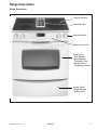
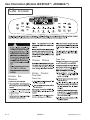
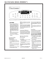
Range Description
Range Description
Cooking Surface
Downdraft Vent
Infinite Switches
Electronic Controls
Oven Cavity:
Broil Element
Bake Element
Convection Fan
Baking Racks
Temperature Probe
Access Panel:
Model Number
Rating Label
©2005 Maytag Services
16025927
9
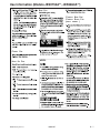
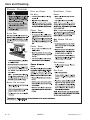
Troubleshooting Procedures
!
WARNING
To avoid risk of electrical shock, personal injury, or death, disconnect power to oven before servicing, unless
testing requires power.
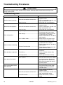
Troubleshooting Chart
Problem
No bake element operation
No broil element operation
Oven not operating
Clock and timer not working
Oven light does not operate
Oven door will not unlock
Oven smokes/odor first few
times of usage
Surface element doesn’t heat
10
Possible Cause
Correction
Open bake element .................................... • Check element for continuity,
replace if failed.
Loose wire connection or broken wire........ • Verify all connections are clean and
tight, replace broken wire.
Open bake relay ......................................... • Verify 240 VAC at bake element.
Open broil element ..................................... • Check element for continuity,
replace if failed.
Loose wire connection or broken wire........ • Verify all connections are clean and
tight, replace broken wire.
Open broil relay .......................................... • Verify 240 VAC at broil element.
Programming error ..................................... • Switch circuit breaker off to oven for
five minutes and try oven again.
Power outage ............................................. • Verify power is present at unit and
circuit breaker is not tripped.
• Replace household fuse, but do not
fuse capacity.
Unit in Sabbath mode................................. • Refer to Use & Care manual and
remove unit from Sabbath mode.
Power outage ............................................. • Verify power is present at unit and
circuit breaker is not tripped.
• Replace household fuse, but do not
fuse capacity.
Electronic Control locked............................ • Refer to Use and Care manual and
unlock electronic control.
Failed oven lamp ........................................ • Check lamp and replace is
necessary.
Failed wiring ............................................... • Check for broken, loose or dirty
connections.
Failed light socket....................................... • Check light socket for continuity.
Oven is self-cleaning .................................. • Allow cycle to complete.
Oven is still hot ........................................... • Will not unlock until unit has cooled
to safe temperature. Do not force
door open, this will void warranty.
Blow cool air on door latch area to
quicken process.
Normal ........................................................ • Minor smoking or order is normal
the first few times of oven usage.
• Ventilate area well and perform
self-clean cycle.
Open element ............................................. • Check element for continuity,
replace if failed.
Loose wire connection or broken wire........ • Verify all connections are clean and
tight, replace broken wiring.
Failed infinite switch ................................... • Check infinite switch, replace if
failed.
16025927
©2005 Maytag Services
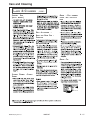
Troubleshooting Procedures
!
WARNING
To avoid risk of electrical shock, personal injury, or death, disconnect power to oven before servicing, unless
testing requires power.
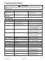
Problem
Self-clean cycle not
working
Frequent cycling of
surface element or
warming zone
Possible Cause
Correction
Programming error ..................................... • Turn off circuit breaker for five minutes
and try oven again.
Door lock .................................................... • Verify door lock energizes & engages.
Normal........................................................ • Element cycles to maintain proper heat
and to prevent damage to smoothtop.
Fault Code Chart
Fault Code
F0-0
F1-1
F1-5
Description
No Fault......................................................
Oven temperature above 650° F
(343° C) in bake mode ...............................
Oven temperature above 950° F
(510° C) during a clean cycle .....................
Cancel pad not responding ........................
F1-7
Membrane disconnected............................
F1-8
Shorted key (pad) in membrane switch .....
F1-9
F1-A
Internal control communication errors........
Lock/unlock switch state not advancing
to control.....................................................
Oven door switch state not advancing to
control.........................................................
Control not calibrated .................................
Jumper not removed from printed circuit
board (PCB) ...............................................
EEPROM error ...........................................
Internal voltage for slave micro incorrect ...
Open or shorted sensor .............................
Shorted meat probe ...................................
F1-3
F1-C
F1-E
F1-F
F1-H
F1-N
F3-1
F8
F9-1
F9-2
F9-3
©2005 Maytag Services
Component to Troubleshoot/Replace
• None.
• Ohm sensor and harness (see "Oven
Sensor" chart). If OK, change control.
• Ohm sensor and harness (see "Oven
Sensor" chart). If OK, change control.
• Ensure ribbon cable is securely
connected, inspect ribbon cable and
connector (shorts, breakage, corrosion,
etc.). If OK, replace control.
• Ensure ribbon cable is securely
connected, inspect ribbon cable and
connector (shorts, breakage, corrosion,
etc.). If OK, replace control.
• Ensure ribbon cable is securely
connected, inspect ribbon cable and
connector (shorts, breakage, corrosion,
etc.). If OK, replace control.
• Replace control.
• Check connections, harness, and
motor. If OK, replace control.
• Check connections, harness, and
motor. If OK, replace control.
• Replace control.
• Remove jumper from PCB.
•
•
•
•
Replace control.
Replace control.
Ohm sensor and harness.
Check probe jack and harness probe
jack harness. If OK, check meat probe
(see "Meat Probe" chart).
Oven door will not lock ............................... • Check wire connections. If OK,
replace motorized door lock.
Oven door will not unlock ........................... • Check wire connections. If OK,
replace motorized door lock.
Oven door status is both locked and
• Check wire connections. If OK,
unlocked ..................................................... replace motorized door lock.
16025927
11
Troubleshooting Procedures
!
WARNING
To avoid risk of electrical shock, personal injury, or death, disconnect power to oven before servicing, unless
testing requires power.
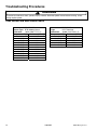
Oven Sensor and Meat Probe Charts
OVEN SENSOR
Sensor Type: RTD 1000Ω platinum
Calibration:
1654Ω (350° F/177° C)
Temperature F (C) Resistance (Ohms)
100 (38)
1143
200 (94)
1350
300 (149)
1553
350 (177)
1654
400 (204)
1753
500 (260)
1949
600 (316)
2142
700 (371)
2331
800 (427)
2516
900 (483)
2697
1000 (538)
2874
12
MEAT PROBE
Type:
NTC Thermistor
Calibration:
9938Ω (150° F/65.5° C)
Temperature F (C) Resistance (Ohms)
122 (50)
18963
150 (65.5)
9938
156.2 (69)
8846
165.2 (74)
7456
210.1 (98.9)
3886
16025927
©2005 Maytag Services
Component Testing Procedures
!
WARNING
To avoid risk of electrical shock, personal injury or death; disconnect power to oven before servicing, unless
testing requires power.
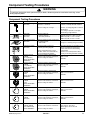
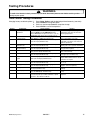
Component Testing Procedures
Illustration
Primary
Secondary
Primary
Secondary
Component
Oven light housing
All models
Test Procedure
Results
Disconnect connector and test
Verify bulb is plugged in properly.
resistance of terminals ........................... Indicates continuity with bulb installed.
Step-down
transformer
All models
Measure voltage at oven light ................ 12 VAC, see wiring diagram for terminal
identification.
If no voltage is present at oven light,
check wiring or light switches.
Measure voltage at:
Primary terminals ............................... 120 VAC (tolerance: 108 to 127 VAC)
Secondary terminals........................... 10W load (bulb): 11.4 to 11.8 VAC
20W load (bulb): 10.8 to 11.4 VAC
Remove switch from unit and measure
the following points:
COM to NO......................................... Plunger in continuity, plunger out infinity.
Door plunger switch
All models
Autolatch assembly
All models
Halogen element
1200 W,
6.5 in.(165 mm)
Models JES9750A**,
JES9860A**
©2005 Maytag Services
Disconnect wires and test for
continuity per wiring diagram.
See wiring diagram for schematic layout.
Access assembly by removing two
screws from the front and lowering
control panel.
Common is in neutral position unless
locking or unlocking autolatch assembly.
Refer to Parts Manual for correct
autolatch switch associated with the
correct manufacturing number.
Disconnect wiring to element and
measure cold resistance of terminals..... Approx. 48 Ω
Measure voltage at element................... 240 VAC
Halogen element
1200 W,
8 in. (200 mm)
Models JES9750A**,
JES9860A**
Disconnect wiring to element and
measure cold resistance of terminals..... Approx. 48 Ω
Measure voltage at element................... 240 VAC
Coil element,
1250 W
4-turn
Models JES9750A**,
JES9860A**
Disconnect wiring to element and
measure cold resistance of terminals..... Approx. 42.5 to 46.9 Ω
Measure voltage at element................... 240 VAC
Coil element,
2100 W
5-turn
Models JES9750A**,
JES9860A**
Disconnect wiring to element and
measure cold resistance of terminals..... Approx. 25.3 to 27.9 Ω
Measure voltage at element................... 240 VAC
Ribbon element
1800 W
Models JES9750A**,
JES9860A**
Disconnect wiring to element and
measure cold resistance of terminals..... Approx. 29 to 32.6 Ω
Measure voltage at element................... 240 VAC
Ribbon element,
1200 W
All models
Disconnect wiring to element and
measure cold resistance of terminals..... Approx. 44.3 to 48.9 Ω
Measure voltage at element................... 240 VAC
Ribbon element,
2200 W (1500 W
inner, 700 W outer)
Model JES9800A**
Disconnect wiring to element and
measure cold resistance of terminals..... Inner: approx. 76 to 84 Ω
Outer: approx. 36.7 to 40.5 Ω
Measure voltage at element................... 240 VAC
16025927
13
Testing Procedures
!
WARNING
To avoid risk of electrical shock, personal injury or death; disconnect power to oven before servicing, unless
testing requires power.
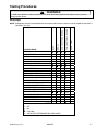
Illustration
TOP
Component
Temperature sensor
All models
Test Procedure
Results
Measure resistance .............................. Approx. 1100 Ω at room temperature
75° F (23.8° C).
Infinite switch
All models
Remove wiring from H1 and H2.
Approx. Time On: Simmer 5%, Off 95%
Connect volt/ohms meter to H1 and
Med (5) 65%, Off 45%
H2 and measure voltages at LO,
Full On 100%, Off 0%
MED, HI................................................ 240 VAC
Dual element infinite
switch
Approx. Time On: Simmer 5%, Off 95%
Remove wiring from H1 and H2.
Med (5) 65%, Off 45%
Connect volt/ohms meter to H1 and
Full On 100%, Off 0%
H2 and measure voltages at LO,
MED, HI................................................ 240 VAC
H1
H2
H1
H2
Model JES9800A**
Bake element
All models
Broil element
All models
Grill assembly
Models JES9750A**,
JES9860A**
Hi-limit temperature
switch
All models
Convection assembly
Convection motor
Models JES9800A**,
JES9860A**
Cooling fan motor
All models
Downdraft motor
Models JES9750A**,
JES9800A**,
JES9860A**
Disconnect wiring to element and
measure cold resistance of terminals. .
Measure voltage at bake element........
Disconnect wiring to element and
measure cold resistance of terminals. .
Measure voltage at broil element.........
Approx. 20.6 to 22.6 Ω.
240 VAC.
Approx. 13.3 to 14.7 Ω.
240 VAC.
Disconnect wiring to element and
measure cold resistance of terminals. . Approx. 2.4 Ω.
Measure voltage at grill element.......... 240 VAC.
Normally closed, verify operation:
Open: 218° to 232°F (103° to 111°C). Infinite.
Closed: 156° to 174°F (69° to 79°C) .. Continuity.
Measure voltage................................... 120 VAC. (tolerance: 105 to 135 VAC)
Check motor windings to ground .......... No continuity.
RPM: Approx. 1750 to 2250.
Measure voltage................................... 120 VAC.
Check motor windings to ground .......... No continuity.
RPM: Idle: 3395
Load: 3000
Breakdown: 2400
Check motor windings to ground .......... No continuity.
RPM: 1550, 2.4 amp.
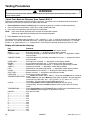
!
WARNING
To avoid risk of electrical shock, personal injury or equipment failure, use extreme caution when taking voltage
measurements in the Electronic Control. Failure to do so could short-circuit the control or result in electrical shock.
Illustration
14
Component
Electronic control
panel
All models
Test Procedure
L1 .........................................................
L1 .........................................................
Jumper .................................................
Jumper .................................................
Door logic sensor .................................
Results
P19 (Black) to P5 (White): 120 VAC
P21 (Black) to P5 (White): 120 VAC
K7 (NC) Broil Relay
K5 (NO) Bake Relay
P4 (Red, pin 5) to P4 (Black, pin 2):
Door Locked:
Continuity
Door Unlocked:
Infinity
Meat probe ........................................... P2 (Red) to P2 (Red). See chart, pg 12.
120 VAC
Downdraft motor high setting................ P14 (Tan) to P5 (White):
Downdraft motor low setting ................. P22 (Orange) to P5 (White): 120 VAC
16025927
©2005 Maytag Services
Testing Procedures
!
WARNING
To avoid risk of electrical shock, personal injury or death; disconnect power to oven before servicing, unless
testing requires power.
Oven Control Testing Procedures
Changing factory set default options: 1.
2.
3.
4.
Control
EOC II
Component
Oven temperature
adjustment
EOC II
End-of-Timer
Reminder beeps
Control Lock
EOC II
EOC II
EOC II
Twelve Hour off/
Sabbath mode
Sound Level
(Beeper Volume)
24-Hour Clock
EOC II
Scroll Speed
EOC II
End-of-Cook-Time
Signal
EOC II
Temperature Display
EOC II
Language Display
EOC II
Factory Default
EOC II
Clock Display
EOC II
Test Access
EOC II
©2005 Maytag Services
Press Setup Options and the desired pad simultaneously (see table).
Press Autoset to change the option.
Press any pad except Cancel to accept the change.
Press Cancel to cancel the operation.
Test Procedure
Press Bake pad and enter 550° F (288° C). Press
and hold Bake pad until TEMP ADJ displays.
Press Autoset pad to adjust oven in 5° F (-15° C)
increments, from -35° F (-37° C) to 35° F (2° C).
Press Setup Options and the applicable timer
pad (Timer 1 or Timer 2) simultaneously.
Press Setup Options and the Control Lock pad
(also the 1 pad) simultaneously.
Press Setup Options and the 12 Hour Off pad
(also the 2 pad) simultaneously.
Press Setup Options and the Sound Level pad
(also the 3 pad) simultaneously.
Press Setup Options and the 12/24 Hour Clock
pad (also the 4 pad) simultaneously.
Press Setup Options and the Scroll Speed pad
(also the 5 pad) simultaneously.
Press Setup Options and Cook Time Beeps
pads (also the 6 pad) simultaneously.
Press Setup Options and the Temp C/F pad
(also the 7 pad) simultaneously.
Press Setup Options and the Language pad
(also the 8 pad) simultaneously.
Press Setup Options and the Default pad (also
the 9 pad) simultaneously.
Press Setup Options and the Display On/Off pad
(also the Clock pad) simultaneously.
Press and hold Cancel and Broil pads for 3
seconds at power up or within 5 minutes of power
up mode. See "Quick Test Mode."
16025927
Results
While increasing or decreasing oven
temperature, this does not affect selfcleaning temperature.
Selects the number of beeps emitted
when a timed bake cycle ends.
Press Autoset to select option (enable
or disable). The timer, clock and oven
light are operational.
Disables the normal 12-hour shutoff,
allowing the oven to operate indefinitely.
Press Autoset to select setting (I lowest
through IIIIIIII 8 highest).
Press Autoset to select option (12-hour
time or 24-hour time).
Press Autoset to set speed of displayed
messages (slow, medium, fast).
Press Autoset to set the number of
beeps emitted at the end of a "clockcontrolled" cook cycle.
Press Autoset to select option
(°F or °C).
Press Autoset to select option
(English, French or Spanish).
Press Autoset to reset clock to factory
settings.
Press Autoset to select clock display (on
or off).
Allows access to each function for testing
purposes.
15
Testing Procedures
!
WARNING
To avoid risk of electrical shock, personal injury or death; disconnect power to oven before servicing, unless
testing requires power.
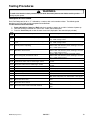
Component
Control Panel Assembly
Test Procedure
Closed circuitry resistance
(defined as continuity):
1350 – 2250 Ω for Cancel pads 1 & 20
1275 – 2125 Ω for Cancel pads 2 & 19
320 – 2200 Ω for all other pads
Open circuitry resistance:
Greater than 10 MΩ
Pin 20
Clock
Quick Preheat
Bake
Broil
Keep Warm
Convect Warm
Convect Roast
Cook Time
Stop Time
Clean
Proofing
Drying
Meat Probe
Vent Fan
Auto Set
Timer 1
Timer 2
Oven Light
Pin 1
16
Results
Pad
1
2
3
4
5
6
7
8
9
0
Cancel
16025927
Trace
7&8
14 & 15
10 & 14
6&7
6&8
5&6
4&5
4&6
3&4
3&6
1 & 2 or
1 & 19 or
2 & 20 or
19 & 20
13 & 14
16 & 18
15 & 16
16 & 17
12 & 13
6 & 10
3 & 18
10 & 18
14 & 18
15 & 18
8 & 10
9 & 10
6 & 18
11 & 12
17 & 18
12 & 14
10 & 12
10 & 11
Measurement
Continuity
Continuity
Continuity
Continuity
Continuity
Continuity
Continuity
Continuity
Continuity
Continuity
Continuity
Continuity
Continuity
Continuity
Continuity
Continuity
Continuity
Continuity
Continuity
Continuity
Continuity
Continuity
Continuity
Continuity
Continuity
Continuity
Continuity
Continuity
Continuity
Continuity
Continuity
Continuity
©2005 Maytag Services
Testing Procedures
!
WARNING
To avoid risk of electrical shock, personal injury or death; disconnect power to oven before servicing, unless
testing requires power.
Relay Logic
IDLE
BAKE PREHEAT
BAKE
HIGH BROIL PREHEAT
HIGH BROIL
LOW BROIL PREHEAT
LOW BROIL
CLEAN PREHEAT
CLEAN
KEEP WARM PREHEAT
KEEP WARM
CONVECT ROAST PREHEAT
CONVECT ROAST
CONVECT BAKE QUICK PREHEAT
CONVECT BAKE PREHEAT
CONVECT BAKE
QUICK PROOFING PREHEAT
QUICK PROOFING
STANDARD PROOFING PREHEAT
STANDARD PROOFING
DRYING PREHEAT
DRYING
INDEX
OVEN LIGHT
CONVECT FAN LO SPEED
r
r
r
r
r
r
O
CONVECT FAN HI SPEED
COOKING MODE
BROIL
BAKE
NOTE: Subsequent changes implemented after the release of this technical sheet may have altered the parameters
identified in this chart.
r r r
r r
r r
O
r r
O
r r
r r
r r
O
r r r
r r r r
r r r
r r r
O* r
O* r
r O*
r O*
r O*
r O*
r O*
r r
r r
O* r
O* r
- OFF
O - ON
- CYCLING
- ON OR OFF (DETERMINED BY USER INPUT)
*Convection fan stops when oven door is opened.
©2005 Maytag Services
16025927
17
Testing Procedures
!
WARNING
To avoid risk of electrical shock, personal injury or death; disconnect power to oven before servicing, unless
testing requires power.
"Quick Test" Mode for Electronic Oven Control (EOC) II
Follow the procedure below to perform the EOC II quick test. Instructions must be entered within 16 seconds of
each other (via the touch pad) or the EOC will exit the test mode.
1. Press and hold the Cancel and Broil pads for 3 seconds at power-up, or within 5 minutes of power-up.
2. Once the control has entered the "Quick Test" mode, release both pads.
3. Press each of the following pads indicated in the table below.
NOTE:
Press and hold the applicable pad to activate the associated response.
Release the applicable pad to deactivate the associated response.
4. Press Cancel to exit the test mode.
The control display window normally displays "lu:d," where the "l" and "u" indicate the state of the motorized door
lock and the "d" indicates oven door input status. Once the applicable pad is pressed and held, the "d" changes
to either a "0" (open switch) or a "1" (closed switch). Once the pad is released, the display will return to "lu:d."
Display will indicate the following:
Pad
Response
BAKE ................................... Bake relay activated, "1" displayed in control display window.
BROIL.................................. Broil relay activated, "1" displayed in control display window.
CONVECT BAKE ................ Convection Bake relay activated, Convection Fan cycles, "1" displayed in control
display window.
CONVECT ROAST ............. Convection Roast relay activated, Convection Fan cycles, "1" displayed in control
display window.
OVEN LIGHT....................... Oven light relay activated, "1" displayed in control display window.
PROBE ................................ Actual Probe temperature and "1" displayed in control display window.
TIMER 1 .............................. Downdraft fan activated at low speed, "1" displayed in control display window.
TIMER 2 .............................. Cooling fan activated, "1" displayed in control display window.
FAN ..................................... Downdraft fan activated at high speed, "1" displayed in control display window.
CLEAN................................. Motorized Door Lock activated, "1" displayed in control display window.
STOP TIME ......................... Beeper activated, "1" displayed in control display window.
COOK TIME ........................ Displays most recent fault code.
TEMPERATURE OFFSET .. Press Bake pad and enter 550° F (288° C). Press and hold Bake pad for 4 seconds,
release Bake pad, then press Bake pad again within 3 seconds. Use the digit pads
(0 through 9) to adjust from -35° F (-37° C) to 35° F (2° C), oven in 5° F (-15° C)
increments. This also applies to the CLEAN temperature.
CLOCK ................................ Press Setup Options and the 12/24 Hour Clock pad (also the 4 pad)
simultaneously, then press Autoset to display time in12-hour format or 24-hour
format.
TEMPERATURE ................. Press Setup Options and the Temp C/F pad (also the 7 pad) simultaneously, then
press Autoset to display degrees in Fahrenheit or Celsius.
CANCEL .............................. Exits the test mode.
0........................................... N/A
1........................................... N/A
2........................................... N/A
3........................................... N/A
4........................................... N/A
5........................................... N/A
6........................................... N/A
7........................................... N/A
8........................................... N/A
9........................................... N/A
AUTOSET............................ N/A
18
16025927
©2005 Maytag Services
Testing Procedures
!
WARNING
To avoid risk of electrical shock, personal injury or death; disconnect power to oven before servicing, unless
testing requires power.
Description of Fault Codes
Each Fault Code consists of an "F" followed by a number, dash and a number or letter. The following table
describes each Fault Code and the component to troubleshoot.
To view the most recent fault code:
1. Press and hold the Cancel and Broil pads for 3 seconds at power-up, or within 5 minutes of power-up.
2. Once the control has entered the "Quick Test" mode, release both pads.
3. Press the Cook Time pad to view the most recent fault (displayed in the control display window).
Fault
Code
F0-0
F1-1
Description
Component to Troubleshoot/Replace
No Fault.
Oven temperature above 650° F (343° C) in bake mode.
None.
Ohm sensor and harness (see "Oven Sensor" chart, pg
12). If OK, change control.
Ohm sensor and harness (see "Oven Sensor" chart, pg
12). If OK, change control.
Ensure ribbon cable is securely connected, inspect
ribbon cable and connector (shorts, breakage, corrosion,
etc.). If OK, replace control.
Ensure ribbon cable is securely connected, inspect
ribbon cable and connector (shorts, breakage, corrosion,
etc.). If OK, replace control.
Ensure ribbon cable is securely connected, inspect
ribbon cable and connector (shorts, breakage, corrosion,
etc.). If OK, replace control.
Replace control.
Check connections, harness, and motor. If OK, replace
control.
Check connections, harness, and motor. If OK, replace
control.
Replace control.
Remove jumper from PCB.
Replace control.
Replace control.
Ohm sensor and harness.
Check probe jack and harness probe jack harness. If
OK, check meat probe (see "Meat Probe" chart, pg 12).
Check wire connections. If OK, replace motorized door
lock.
Check wire connections. If OK, replace motorized door
lock.
Check wire connections. If OK, replace motorized door
lock.
F1-3
Oven temperature above 950° F (510° C) during a clean
cycle.
F1-5
Cancel pad not responding.
F1-7
Membrane disconnected.
F1-8
Shorted key (pad) in membrane switch.
F1-9
Internal control communication errors.
F1-A
Lock/unlock switch state not advancing to control.
F1-C
Oven door switch state not advancing to control.
F1-E
F1-F
F1-H
F1-N
F3-1
Control not calibrated.
Jumper not removed from printed circuit board (PCB).
EEPROM error.
Internal voltage for slave micro incorrect.
Open or shorted sensor.
F8
Shorted meat probe.
F9-1
Oven door will not lock.
F9-2
Oven door will not unlock.
F9-3
Oven door status is both locked and unlocked.
©2005 Maytag Services
16025927
19
Disassembly Procedures
To avoid risk of electrical shock, personal injury or
death; disconnect power to unit before servicing.
Removing and Replacing Range
1. Remove power from unit.
2. Disconnect downdraft blower motor and remove flex
ducting to the blower and range (select models).
NOTE: To avoid countertop damage, do not move
range forward until range has been raised
enough to clear all cabinetry.
8. Remove screws securing element mounting brackets
to main top assembly (select models).
9. Gently remove elements from mounting brackets to
prevent damage to glass top (select models).
10.Reverse procedure to reinstall maintop assembly.
Control Panel
3. Pull the range forward out of the cabinet opening.
4. Disconnect or unplug the power cord leading from
unit to fuse box or junction box depending on unit.
5. Replace the oven using the installation instructions
and anti-tip bracket(s).
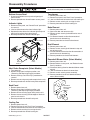
Cartridge Assembly (Select Models)
Cooktop cartridges can be installed on either side of the
range cooktop.
1. Remove power from unit.
2. Lift up on the tab (located on the cartridge) until top of
cartridge clears the opening on the range by 2 inches.
NOTE: Lifting the cartridge too high while still engaged
in the receptacle could damage the terminal
plug.
1. Remove power from unit.
2. Open oven door and remove screws securing control
panel.
3. Remove screws located on the right and left sides of
the control panel.
4. Grasp control panel on the far left and right sides and
gently pull the control panel out and down.
NOTE: Gently pull control panel out and down.
5. Remove infinite switch control knobs, infinite
switches, indicator lights, rocker switches, and
electronic control/clock (as necessary) and transfer to
the new control panel.
6. Reverse procedure to reinstall control panel.
Electronic Control
1. Remove control panel, see “Control Panel”
procedure, steps 1 through 4.
2. Remove screws securing electronic control bracket to
control panel.
3. Label and disconnect terminal wiring from electronic
control.
4. Reverse procedure to reinstall electronic control.
3. Hold cartridge by the sides and slide away from
terminal receptacle.
4. Lift cartridge out when fully unplugged.
Electronic
Control
Control
Panel
Install cartridges here
Maintop Assembly
1. Remove power from unit.
2. Remove range from installation position, see
“Removing and Replacing Range” procedure.
3. Remove air grill, filter, grill grates, aeration pan and
cartridges (select models).
4. Remove screws from plenum area at front of opening.
5. Open oven door and remove screws securing
maintop to oven chassis, located on the bottom of
control panel and along the outside edges of the
maintop.
6. Remove cartridge receptacles and grill pans (select
models).
7. Label and disconnect wiring to elements (select
models).
20
Infinite Switch
1. Remove control panel, see "Control Panel" procedure
for removal.
2. Label and disconnect wire terminals from infinite
switch.
3. Remove knob on infinite switch being replaced.
4. Remove screws in front securing infinite switch to
control panel.
5. Reverse procedure to reinstall infinite switch.
16025927
©2005 Maytag Services
Disassembly Procedures
To avoid risk of electrical shock, personal injury or
death; disconnect power to unit before servicing.
Bottom Access Panel
Transformer
1. Grasp top of bottom access panel and gently pull
down and out.
2. Reverse procedure to reinstall bottom access panel.
1.
2.
3.
4.
5.
Indicator Lights
1. Remove control panel, see "Control Panel" procedure
for removal.
2. Label and disconnect wires from indicator light.
3. Squeeze the two tabs on the indicator light body and
gently pull to release from control panel.
4. Reverse procedure to reinstall indicator light.
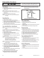
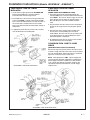
Oven Sensor
Bake Element
1. Remove power from unit.
2. Open oven door and remove rack(s).
3. Remove screws securing bake element to rear of
cavity wall.
4. Pull element forward to allow disconnection of
terminals on each element leg.
5. Reverse procedure to reinstall bake element.
Broil Element
Cooling
Fan
Transformer
Broil Element
Bake
Element
Remove power from unit.
Remove back panel, see "Back Panel" procedure.
Label and disconnect wire terminals from cooling fan.
Remove screws securing fan to range chassis.
Reverse procedure to reinstall cooling fan.
1. Remove power from unit.
2. Remove screws securing broil element to top and
rear of oven cavity.
3. Pull broil element forward to allow disconnection of
terminals on each element leg.
4. Reverse procedure to reinstall broil element.
Downdraft Blower Motor (Select Models)
Meat
Probe
Meat Probe Receptacle (Select Models)
1. Turn power off.
2. Remove range from installation position, see
“Removing and Replacing Range” procedure.
3. Remove main top, see "Main Top" procedure for
removal.
4. Remove nut securing meat probe receptacle to cavity.
5. Reverse procedure to reinstall meat probe receptacle.
1. Remove power from unit.
2. Remove bottom access panel, see "Bottom Access
Panel" procedure.
3. Disconnect ducting allow for downdraft blower motor
removal.
4. Label and disconnect electrical connections.
5. Remove screws securing motor assembly.
6. Reverse procedure to reinstall downdraft blower
motor (select models).
Back Panel
1. Remove power from unit.
2. Remove range from installation position, see
“Removing and Replacing Range” procedure.
3. Remove screws securing upper back panel to unit.
4. Remove screws securing outside edges of the back
panel to unit chassis.
5. Reverse procedure to reinstall back panel.
Downdraft
blower motor
assembly
Cooling Fan
1.
2.
3.
4.
5.
Remove power from unit.
Remove back panel, see "Back Panel" procedure.
Label and disconnect wire terminals from cooling fan.
Remove screws securing fan to range chassis.
Reverse procedure to reinstall cooling fan.
©2005 Maytag Services
16025927
21
Disassembly Procedures
To avoid risk of electrical shock, personal injury or
death; disconnect power to unit before servicing.
Oven Sensor
1. Remove power from unit.
2. Open oven door and remove screws securing sensor
to oven cavity.
NOTE: Reposition fiberglass insulation around light
socket to eliminate the possibility of any heat
related problems.
Bulb
NOTE: Gently pull wiring through cavity wall.
3. Disconnect oven sensor at the connector terminal
and remove.
4. Reverse procedure to reinstall sensor.
Socket
NOTE: Verify sensor wires are pushed through the
insulation.
Lens
Bulb specifications
G5.3 Type Halogen Bi-Pin 25W-120V
Front Side Trim
1. Remove power from unit.
2. Slide unit out far enough to access side trim.
3. Remove screws securing front side trim piece(s) to
oven chassis (left and right trim pieces).
4. Gently grasp trim piece with both hands, pull forward
and roll trim piece off retainer clips.
5. Reverse procedure to reinstall front side trim piece(s).
Oven Light Bulb/Oven Light Socket
NOTE: Requires removal of unit to replace oven light
socket.
The light automatically comes on when the door is
opened. The light will not operate during a clean cycle.
1. Remove power from unit.
2. Open oven door and locate oven light.
3. Grasp lens cover and pull outward on one side to
gain access to bulb.
4. Carefully remove old bulb, by lifting bulb straight out
of ceramic base.
NOTE: To avoid damaging the new bulb and
decreasing life of the bulb, do not touch new
bulb with bare hands or fingers.
Hold with a cloth or paper towel.
NOTE: Proceed with the following steps for oven light
socket removal.
5. Remove unit from installation position, see
“Removing and Replacing Range” procedure.
6. Disconnect or unplug the power cord leading from
unit to fuse box or junction box depending on unit.
7. Carefully displace fiberglass insulation away from
rear of light socket.
8. Release metal tabs on light socket and push socket
assembly away from the oven cavity.
9. Label and disconnect wires from light socket.
10.Reverse procedure to reinstall light socket.
Reposition insulation around lamp socket.
22
Oven Light Switch
1. Remove power from unit.
2. Remove control panel, see "Control Panel"
procedure.
3. Remove screws securing oven light switch to front of
oven chassis.
3. Reverse procedure to reinstall oven light switch.
Convection Fan
1. Remove power from unit.
2. Remove screws securing convection motor cover to
oven chassis (screws at 12, 4 & 8 o'clock positions).
3. Remove screws securing convect motor to chassis.
4. Gently slide convection motor into oven cavity.
5. Label and disconnect electrical connection.
6. Replace and reverse procedure to reinstall motor.
Oven Vent/Smoke Eliminator
1. Remove power from unit.
2. Locate tabs on bottom of smoke eliminator and turn
counterclockwise to release locking ears.
3. Gently pull smoke eliminator down and align locking
ears with notches in oven cavity to remove.
4. Reverse procedure to reinstall smoke eliminator.
Hi-Limit Thermostat
1. Remove maintop assembly, see "Maintop Assembly"
procedure.
2. Remove screws securing hi-limit thermostat to oven
chassis.
3. Reverse procedure to reinstall hi-limit thermostat.
16025927
©2005 Maytag Services
Disassembly Procedures
To avoid risk of electrical shock, personal injury or
death; disconnect power to unit before servicing.
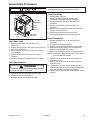
Door
Latch
Oven Door Hinge
1. Remove power from unit.
2. Remove unit from installation position, see
“Removing and Replacing Range” procedure.
3. Remove oven door, see "Oven Door Removal"
procedure.
4. Remove front side trim, see "Front Side Trim"
procedure.
5. Remove the top and bottom screws securing hinge
receiver to the front frame.
6. Remove hinge receiver from oven chassis.
7. Reverse procedure to reinstall oven door hinge.
Hi-Limit
Thermostat
Oven
Light
Switch
Door Hinge
Receiver
Convection
Fan
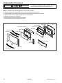
Door Disassembly
Oven Door Latch
1. Remove control panel, see "Control Panel"
procedure.
2. Remove screws securing door latch to the front of the
oven cavity outer shell.
3. Remove screws securing door light switch to door
latch assembly.
4. Label and disconnect wire terminals from latch
assembly.
5. Reverse procedure to reinstall door latch assembly.
Oven Door Removal
!
WARNING
To avoid risk of personal injury or property damage,
do not lift oven door by the handle.
1. Open oven door and grasp door on both sides.
2. Lift up and off the hinge receivers.
3. Reverse procedure to reinstall oven door.
©2005 Maytag Services
1. Remove oven door, see "Oven Door Removal"
procedure.
2. Place door on a protected surface.
3. Remove screws securing bottom trim to oven door.
4. Slide outer oven door glass and trim towards the
bottom of the oven door and remove.
5. Detach right and left trim pieces for outer door glass.
NOTE: Proceed with the following steps for door handle
and inner door disassembly.
6. Remove screws securing top door handle trim to
oven door chassis.
7. Remove screws securing door handle brackets to
inner door panel.
8. Lift upward on the lower side of the door handle to
release side alignment screws and rotate towards the
top of the oven door to release and remove.
9. Remove screws securing door handle to door handle
brackets.
16025927
23
Disassembly Procedures
To avoid risk of electrical shock, personal injury or
death; disconnect power to unit before servicing.
NOTE: Proceed with the following steps for inner door disassembly.
10.Remove screws securing lower door glass retainer to door baffle and remove.
11 Slide inner door glass downward to release from upper door glass retainers and remove.
12.Remove screws securing door baffle to door lining and remove.
13.Remove insulation from oven door.
14.Lift inner glass and glass frame from oven door.
15.Reverse procedure to reassemble oven door.
Door Gasket
Door Lining
Inner Glass
Glass Frame
Oven Door Insulation
Inner Glass
Door Handle
Door Trim
Door Baffle
Door Glass
Door
Trim
Glass
Retainer
Access Panel
Glass
Door
Door Trim
Glass Support
24
16025927
©2005 Maytag Services
Appendix A
©2005 Maytag Services
16025927
A–1
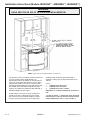
Installation Instructions (Models JES8750AA*, JES8850A**)
IMPORTANT
PLEASE KEEP FOR THE USE OF THE LOCAL ELECTRICAL INSPECTOR.
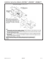
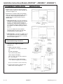
FIGURE 1
NOTE: Figure may not be representative of actual unit.
The 30 inches (76.2 cm) minimum clearance between the
top of the cooking surface and the bottom of an
unprotected wood or metal cabinet can be reduced to 24
inches (61 cm) minimum when bottom of wood or metal
cabinet is protected by not less than 1/4-inch (6.4 mm)
thick flame-retardant millboard covered with not less than
No. 28 MSG sheet steel, 0.015-inch (0.381 mm) thick
stainless steel, 0.024-inch (0.610 mm) thick aluminum, or
0.020-inch (0.508 mm) thick copper.
To eliminate the risk of burns or fire by reaching over
heated surface units, cabinet storage space located
above the surface units should be avoided. If cabinet
storage is to be provided, the risk can be reduced by
A–2
installing a range hood that projects horizontally a
minimum of 5 inches (13 cm) beyond the bottom of the
cabinets.
FIGURE 1
1 . . . COMBUSTIBLE BACK WALL.
2 . . . COMBUSTIBLE SIDE WALL.
3 . . . COMBUSTIBLE WALL CABINET.
DIMENSION “A” IS TO BE A MINIMUM OF 3 INCHES (7.5
CM).
A SLIDE-IN RANGE, IF EQUIPPED WITH OPTIONAL
BACKGUARD KIT, MAY BE INSTALLED ZERO INCHES
FROM COMBUSTIBLE WALL 1 (SEE FIGURE 1).
16025927
©2005 Maytag Services
Installation Instructions (Models JES8750AA*, JES8850A**)
FIGURE 2
FIGURE 3
Notes:
1. Provide for either a 3-wire or 4-wire 120/208, 120/240 volt outlet per applicable cord in shaded area shown. Refer
to installation instructions for proper positioning of outlet.
2. Dimension K (figure 4, page 4) is from the wall to the side edge of the oven door. It does not include the curvature
of the glass or the depth of the handle.
3. Dimension L (figure 4, page 4) is with the leveler legs adjusted all the way in. This may vary slightly upon leveling
leg adjustment.
4. Do not use grout, epoxy, etc., to install this unit. Installation must allow for removal of this appliance from the
installed location for purposes of servicing.
IMPORTANT: Because of continuing pr oduct improvements, Maytag reserves the right to change specifications
without notice. Dimensional specifications are provided for planning purposes only. For complete details see
installation instructions that accompany each pr oduct before selecting cabinetry, making cutouts or beginning
installation.
©2005 Maytag Services
16025927
A–3
Installation Instructions (Models JES8750AA*, JES8850A**)
MOBILE HOMES
LOCATING THE
RANGE
The installation of a range designed for mobile home
installation must conform with the Manufactured Home
Construction and Safety Standard, Title 24 CFR, Part
3280 (formerly the Federal Standard for Mobile Home
Construction and Safety, Title 24 HUD, Part 280) or,
when such standard is not applicable, the Standard for
Manufactured Home Installations 1982 (Manufactured
Home Sites, Communities and Set-Ups), ANSI
A225.1-latest edition, or with local codes.
Place range in a well lit area. Do not set range over holes
in the floor or other locations where it may be subject to
strong drafts. Any opening in the wall behind the range
and in the floor under the range should be sealed. Make
sure the flow of cooling/ventilation air is not obstructed
below the range.
NOTE: A range should NOT be installed over kitchen
carpeting.
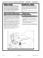
ANTI-TIP DEVICE INSTALLATION
INSTRUCTIONS
WARNING: A risk of range tip-over exists if the appliance
is not installed in accordance with the provided installation
instructions. The proper use of this device minimizes the
risk of TIP-OVER. In using this device the consumer must
still observe the safety precautions as stated in the USE
and CARE MANUAL and avoid using the oven doors as a
step stool.
Installation instructions are provided for wood and cement
in either floor or wall. Any other type of construction may
require special installation techniques as deemed
necessary to provide adequate fastening of the ANTI-TIP
bracket to the floor or wall. The bracket may be installed
to engage the LEFT or RIGHT rear leveling foot.
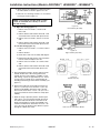
STEP 1 - Locating The Anti-tip Bracket (See Figure
5)
A. Determine where either the right or left “EDGE” of the
range will be located and mark the floor or wall.
B. Place the BRACKET 15/16 (24mm) from the marked
“EDGE” toward center of opening and against the
back wall as shown in figure 5, with orientation hole
against wall.
C. Use the bracket as a template and mark the required
holes, as shown in figure 5, for the type of
construction you will be using.
D. Anti-tip bracket may be secured to either floor or wall.
See Step 2 on page 6 for bracket installation options.
NOTE: The bracket provided is designed for use with
flush mount and non-flush mount outlet receptacles.
Install the bracket with the orientation hole in the longer
leg against the wall as shown in figure 5.
FIGURE 5
A–4
16025927
©2005 Maytag Services
Installation Instructions (Models JES8750AA*, JES8850A**)
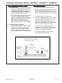
STEP 2 - Anti-Tip Bracket Installation
Options
A. Wood Construction:
1. Floor: Locate the center of the two holes identified in
figure 5 as “HOLES FOR FLOOR.” Drill a 1/8 (3
mm) pilot hole in the center of each hole (a nail or
awl may be used if a drill is not available). Secure the
ANTI-TIP bracket to the floor with the two screws
provided. Proceed to STEP 3.
2. Wall: Locate the center of the two holes identified in
figure 5 as “HOLES FOR WALL.” Drill an angled
1/8 (3 mm) pilot hole in the center of each hole as
shown in figure 6. (A nail or awl may be used if a drill
is not available). Securethe ANTI-TIP bracket to the
wall with the two screws provided as shown in figure
6. Proceed to STEP 3.
B. Cement or Concrete Construction:
1. Suitable screws for concrete construction can be
obtained at the hardware store. Drill the required
size hole for the hardware obtained into the
concrete at the center of the holes identified in figure
5 as “HOLES FOR FLOOR”. Secure the ANTI-TIP
bracket to the floor. Proceed to STEP 3.
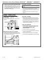
STEP 3 - Range Installation
A. A Jenn-Air range may be installed by one person.
B. Align the range to its designated location and slide it
back into position. Note: A minimum clearance of 1/4
(6 mm) is required between the range and the leveling
foot that will engage the ANTI-TIP bracket, see figure
6.
C. All Jenn-Air ranges have a non lift-up top.
D. For SAFETY CONSIDERATIONS as well as optimum
performance adjust the range so that it is level. This
may be checked by placing a spirit level or a large
pan of water on the cooktop or the oven rack. If an
adjustment is required pull the range forward, tip the
range and rotate the leveling feet as required.
E. To check the range for proper installation of the
anti-tip bracket: Use a flashlight and look underneath
the bottom of the range to see that one of the rear
leveling feet is engaged in the bracket slot.
F. Proceed with the remainder of the installation
instructions provided with the range.
FIGURE 6
©2005 Maytag Services
16025927
A–5
Installation Instructions (Models JES8750AA*, JES8850A**)
CONNECTING THE
RANGE
ELECTRIC SUPPLY
RANGE CONNECTIONS
The range must be installed in accordance with Local and
National Electric Code (NEC) ANSI/NFPA No. 70-latest
edition. See rating plate for total connected KW rating.
Some models are shipped direct from the factory with
service cords (pigtails) attached. There are no range
connections necessary on these models. Just plug into
the range outlet. On models not provided with a service
cord, connection to the power supply is necessary.
REMEMBER - only a 4-conductor cord is to be used on
new branch-circuit installations (1996 NEC), mobile
homes, recreational vehicles, or in an area where local
codes prohibit grounding through the neutral conductor.
Hence, 4-wire service MUST be provided for such
installations. 3-wire service may be used when permitted
by local code. USE COPPER OR ALUMINUM
CONDUCTORS. Main terminal block is recognized for
Copper or Aluminum conductors. If a flexible power cord
is required, it is recommended a cord no longer than 4 ft.
be used. Make connections as explained below and with
reference to the appropriate illustration (see figures 8 and
9). After installation, insure tightness of all electrical
connections and replace all covers.
ELECTRIC SUPPLY (Canada)
The range must be installed in accordance with Local and
Canadian Electric Code CSA STD.C22.1 latest edition.
See rating plate for total connected KW rating.
OUTSIDE WIRING
Your local utility company will tell you whether the present
electric service to your home is adequate. It may be
necessary to increase the size of the wiring to the house
and service switch to take care of the electrical load
demanded by the range. The kilowatt rating for the range
is specified on the rating plate located on the front of the
range.
HOUSE WIRING
Most local Building Regulations and Codes require that all
electrical wiring be done by licensed electricians. All
wiring should conform to Local and National Electrical
Codes. This range requires a single phase three wire
120/240 or a 120/208 volt, 60 Hz, AC circuit. Wiring codes
require a separate circuit be run from the main entrance
panel to the range and that it be equipped with separate
disconnect switch and fuses, either in the main entrance
panel or in a separate switch and fuse box. In some
communities, a solid or flexible continuous armored
conduit must be used from main entrance panel to the
terminal box on the rear of the range. Others will permit
the termination of the range circuit at a polarized three or
four wire plug-in outlet placed at a convenient point near
the back of the range. The range is then connected to this
outlet through an approved range connector (pigtail)
fastened securely to the terminal block with proper strain
relief at the range and a three or four pronged plug at the
opposite end.
Remove terminal block access cover from range back.
(See figure 7).
RANGE CONNECTIONS (Canada)
This model was shipped direct from the factory with
service cord (pigtail) attached. There are no range
connections necessary. Just plug into the range outlet.
See figure 2 on page 3 for outlet location.
NOTE: Cord replacement - ONLY a power supply cord
rated at 240 volts minimum, 40 amperes or 50 amperes
power supply cord that is marked for use with nominal
1 3/8 (34.93 mm) diameter connection opening, with
closed loop terminals and marked for use with ranges
shall be used.
FIGURE 7
A–6
16025927
©2005 Maytag Services
Installation Instructions (Models JES8750AA*, JES8850A**)
3-WIRE SERVICE CORD OR CONDUIT
INSTALLATION
4-WIRE SERVICE CORD OR CONDUIT
INSTALLATION
1. Insure that the copper ground strap IS CONNECTED
between the middle post of the main terminal
connection block and the range chassis.
(MOBILE HOMES OR AS REQUIRED BY CODES)
1. The copper ground strap connected between the
neutral (middle) post of the main terminal block and the
chassisMUST be cut off as shown in figure 9. Save the
green ground screw to attach the ground from the 4
wire cord. Only a 4 wire cord or conduit should be
used.
2. The middle wire of the service cord or ground lead of
3-wire conduit MUST connect to the neutral (middle)
post of the main terminal block. The other two wires of
the service cord or conduit connect to the outside
posts of the main terminal connection block. Polarity is
unimportant.
3. A appropriate strain relief for service cord or conduit
must be attached to the conduit plate.
2. The ground wire from the service cord or conduit must
connect to the range chassis using the green ground
screw.
3. The white wire of the service cord or conduit must
connect to the neutral (middle) post of the main
terminal block. The other two wires of the service cord
or conduit connect to the red and black posts of the
main terminal block, respectively.
4. An appropriate strain relief for service cord or conduit
must be attached to the conduit plate.
CONVERSION FROM 3-WIRE TO 4-WIRE
SERVICE
(Model With 3-Wire Service Cord Attached)
Disconnect range from power. Remove the access cover
on back of range and remove the 3-wire service cord from
the main terminal block. Follow instructions as outlined in
figure 9 to connect the 4-wire service cord.
FIGURE 8
ACCEPTABLE 3-WIRE PLUG INSTALLATION
NOTE: Cord replacement - ONLY a power supply cord
rated at 240 volts minimum, 40 amperes or 50 amperes
power supply cord that is marked for use with nominal
1 3/8 (34.93 mm) diameter connection opening, with
closed loop terminals and marked for use with ranges
shall be used.
FIGURE 9
ACCEPTABLE 4-WIRE PLUG INSTALLATION
©2005 Maytag Services
16025927
A–7
Installation Instructions (Models JES9750A**, JES9800A**, JES9860A**)
IMPORTANT
PLEASE KEEP FOR THE USE OF THE LOCAL ELECTRICAL INSPECTOR.
FIGURE 1
NOTE: Figure may not be representative of actual unit.
The 30 inches (76.2 cm) minimum clearance between the
top of the cooking surface and the bottom of an
unprotected wood or metal cabinet can be reduced to 24
inches (61 cm) minimum when bottom of wood or metal
cabinet is protected by not less than 1/4-inch (6.4 mm)
thick flame-retardant millboard covered with not less than
No. 28 MSG sheet steel, 0.015-inch (0.381 mm) thick
stainless steel, 0.024-inch (0.610 mm) thick aluminum, or
0.020-inch (0.508 mm) thick copper.
To eliminate the risk of burns or fire by reaching over
heated surface units, cabinet storage space located
above the surface units should be avoided. If cabinet
storage is to be provided, the risk can be reduced by
A–8
16025927
installing a range hood that projects horizontally a
minimum of 5 inches (13 cm) beyond the bottom of the
cabinets.
FIGURE 1
1 . . . COMBUSTIBLE BACK WALL.
2 . . . COMBUSTIBLE SIDE WALL.
3 . . . COMBUSTIBLE WALL CABINET.
DIMENSION “A” IS TO BE A MINIMUM OF 3 INCHES (7.5
CM).
A SLIDE-IN RANGE, IF EQUIPPED WITH OPTIONAL
BACKGUARD KIT, MAY BE INSTALLED ZERO INCHES
FROM COMBUSTIBLE WALL 1 (SEE FIGURE 1).
©2005 Maytag Services
Installation Instructions (Models JES9750A**, JES9800A**, JES9860A**)
FIGURE 2
FIGURE 3
Notes:
1. Provide for either a 3-wire or 4-wire 120/208, 120/240 volt outlet per applicable cord in shaded area shown. Refer
to installation instructions for proper positioning of outlet.
2. Dimension K (figure 4, page 4) is from the wall to the side edge of the oven door. It does not include the curvature
of the glass or the depth of the handle.
3. Dimension L (figure 4, page 4) is with the leveler legs adjusted all the way in. This may vary slightly upon leveling
leg adjustment.
4. Do not use grout, epoxy, etc., to install this unit. Installation must allow for removal of this appliance from the
installed location for purposes of servicing.
IMPORTANT: Because of continuing pr oduct improvements, Maytag reserves the right to change specifications
without notice. Dimensional specifications are provided for planning purposes only. For complete details see
installation instructions that accompany each pr oduct before selecting cabinetry, making cutouts or beginning
installation.
©2005 Maytag Services
16025927
A–9
Installation Instructions (Models JES9750A**, JES9800A**, JES9860A**)
MOBILE HOMES
LOCATING THE
RANGE
The installation of a range designed for mobile home
installation must conform with the Manufactured Home
Construction and Safety Standard, Title 24 CFR, Part
3280 (formerly the Federal Standard for Mobile Home
Construction and Safety, Title 24 HUD, Part 280) or,
when such standard is not applicable, the Standard for
Manufactured Home Installations 1982 (Manufactured
Home Sites, Communities and Set-Ups), ANSI
A225.1-latest edition, or with local codes.
Place range in a well lit area. Do not set range over holes
in the floor or other locations where it may be subject to
strong drafts. Any opening in the wall behind the range
and in the floor under the range should be sealed. Make
sure the flow of cooling/ventilation air is not obstructed
below the range.
NOTE: A range should NOT be installed over kitchen
carpeting.
ANTI-TIP DEVICE INSTALLATION
INSTRUCTIONS
WARNING: A risk of range tip-over exists if the appliance
is not installed in accordance with the provided installation
instructions. The proper use of this device minimizes the
risk of TIP-OVER. In using this device the consumer must
still observe the safety precautions as stated in the USE
and CARE MANUAL and avoid using the oven doors as a
step stool.
Installation instructions are provided for wood and cement
in either floor or wall. Any other type of construction may
require special installation techniques as deemed
necessary to provide adequate fastening of the ANTI-TIP
bracket to the floor or wall. The bracket may be installed
to engage the LEFT or RIGHT rear leveling foot.
STEP 1 - Locating The Anti-tip Bracket (See Figure
5)
A. Determine where either the right or left “EDGE” of the
range will be located and mark the floor or wall.
B. Place the BRACKET 15/16 (24mm) from the marked
“EDGE” toward center of opening and against the
back wall as shown in figure 5, with orientation hole
against wall.
C. Use the bracket as a template and mark the required
holes, as shown in figure 5, for the type of
construction you will be using.
D. Anti-tip bracket may be secured to either floor or wall.
See Step 2 on page 6 for bracket installation options.
NOTE: The bracket provided is designed for use with
flush mount and non-flush mount outlet receptacles.
Install the bracket with the orientation hole in the longer
leg against the wall as shown in figure 5.
FIGURE 5
A – 10
16025927
©2005 Maytag Services
Installation Instructions (Models JES9750A**, JES9800A**, JES9860A**)
STEP 2 - Anti-Tip Bracket Installation
Options
A. Wood Construction:
1. Floor: Locate the center of the two holes identified
in figure 5 as “HOLES FOR FLOOR.” Drill a 1/8
(3 mm) pilot hole in the center of each hole (a nail
or awl may be used if a drill is not available).
Secure the ANTI-TIP bracket to the floor with the
two screws provided. Proceed to STEP 3.
2. Wall: Locate the center of the two holes identified
in figure 5 as “HOLES FOR WALL.” Drill an
angled 1/8 (3 mm) pilot hole in the center of each
hole as shown in figure 6. (A nail or awl may be
used if a drill is not available). Secure the
ANTI-TIP bracket to the wall with the two screws
provided as shown in figure 6. Proceed to STEP
3.
B. Cement or Concrete Construction:
1. Suitable screws for concrete construction can be
obtained at the hardware store. Drill the required
size hole for the hardware obtained into the
concrete at the center of the holes identified in
figure 5 as “HOLES FOR FLOOR”. Secure the
ANTI-TIP bracket to the floor. Proceed to STEP 3.
STEP 3 - Range Installation
A. A Jenn-Air range may be installed by one person.
B. Align the range to its designated location and slide it
back into position. Note: A minimum clearance of 1/4
(6 mm) is required between the range and the leveling
foot that will engage the ANTI-TIP bracket, see figure
6.
C. All Jenn-Air ranges have a non lift-up top.
D. For SAFETY CONSIDERATIONS as well as optimum
performance adjust the range so that it is level. This
may be checked by placing a spirit level or a large
pan of water on the cooktop or the oven rack. If an
adjustment is required pull the range forward, tip the
range and rotate the leveling feet as required.
E. To check the range for proper installation of the
anti-tip bracket: Use a flashlight and look underneath
the bottom of the range to see that one of the rear
leveling feet is engaged in the bracket slot.
F. Proceed with the remainder of the installation
instructions provided with the range.
FIGURE 6
©2005 Maytag Services
16025927
A – 11
Installation Instructions (Models JES9750A**, JES9800A**, JES9860A**)
CONNECTING THE
RANGE
ELECTRIC SUPPLY
RANGE CONNECTIONS
The range must be installed in accordance with Local and
National Electric Code (NEC) ANSI/NFPA No. 70-latest
edition. See rating plate for total connected KW rating.
Some models are shipped direct from the factory with
service cords (pigtails) attached. There are no range
connections necessary on these models. Just plug into
the range outlet. On models not provided with a service
cord, connection to the power supply is necessary.
REMEMBER - only a 4-conductor cord is to be used on
new branch-circuit installations (1996 NEC), mobile
homes, recreational vehicles, or in an area where local
codes prohibit grounding through the neutral conductor.
Hence, 4-wire service MUST be provided for such
installations. 3-wire service may be used when permitted
by local code. USE COPPER OR ALUMINUM
CONDUCTORS. Main terminal block is recognized for
Copper or Aluminum conductors. If a flexible power cord
is required, it is recommended a cord no longer than 4 ft.
be used. Make connections as explained below and with
reference to the appropriate illustration (see figures 8 and
9). After installation, insure tightness of all electrical
connections and replace all covers.
ELECTRIC SUPPLY (Canada)
The range must be installed in accordance with Local and
Canadian Electric Code CSA STD.C22.1 latest edition.
See rating plate for total connected KW rating.
OUTSIDE WIRING
Your local utility company will tell you whether the present
electric service to your home is adequate. It may be
necessary to increase the size of the wiring to the house
and service switch to take care of the electrical load
demanded by the range. The kilowatt rating for the range
is specified on the rating plate located on the front of the
range.
HOUSE WIRING
Most local Building Regulations and Codes require that all
electrical wiring be done by licensed electricians. All
wiring should conform to Local and National Electrical
Codes. This range requires a single phase three wire
120/240 or a 120/208 volt, 60 Hz, AC circuit. Wiring codes
require a separate circuit be run from the main entrance
panel to the range and that it be equipped with separate
disconnect switch and fuses, either in the main entrance
panel or in a separate switch and fuse box. In some
communities, a solid or flexible continuous armored
conduit must be used from main entrance panel to the
terminal box on the rear of the range. Others will permit
the termination of the range circuit at a polarized three or
four wire plug-in outlet placed at a convenient point near
the back of the range. The range is then connected to this
outlet through an approved range connector (pigtail)
fastened securely to the terminal block with proper strain
relief at the range and a three or four pronged plug at the
opposite end.
Remove terminal block access cover from range back.
(See figure 7).
RANGE CONNECTIONS (Canada)
This model was shipped direct from the factory with
service cord (pigtail) attached. There are no range
connections necessary. Just plug into the range outlet.
See figure 2 on page 3 for outlet location.
NOTE: Cord replacement - ONLY a power supply cord
rated at 240 volts minimum, 40 amperes or 50 amperes
power supply cord that is marked for use with nominal
1 3/8 (34.93 mm) diameter connection opening, with
closed loop terminals and marked for use with ranges
shall be used.
FIGURE 7
A – 12
16025927
©2005 Maytag Services
Installation Instructions (Models JES9750A**, JES9800A**, JES9860A**)
3-WIRE SERVICE CORD OR CONDUIT
INSTALLATION
4-WIRE SERVICE CORD OR CONDUIT
INSTALLATION
1. Insure that the copper ground strap IS CONNECTED
between the middle post of the main terminal
connection block and the range chassis.
(MOBILE HOMES OR AS REQUIRED BY CODES)
1. The copper ground strap connected between the
neutral (middle) post of the main terminal block and the
chassisMUST be cut off as shown in figure 9. Save the
green ground screw to attach the ground from the 4
wire cord. Only a 4 wire cord or conduit should be
used.
2. The middle wire of the service cord or ground lead of
3-wire conduit MUST connect to the neutral (middle)
post of the main terminal block. The other two wires of
the service cord or conduit connect to the outside
posts of the main terminal connection block. Polarity is
unimportant.
3. A appropriate strain relief for service cord or conduit
must be attached to the conduit plate.
2. The ground wire from the service cord or conduit must
connect to the range chassis using the green ground
screw.
3. The white wire of the service cord or conduit must
connect to the neutral (middle) post of the main
terminal block. The other two wires of the service cord
or conduit connect to the red and black posts of the
main terminal block, respectively.
4. An appropriate strain relief for service cord or conduit
must be attached to the conduit plate.
CONVERSION FROM 3-WIRE TO 4-WIRE
SERVICE
(Model With 3-Wire Service Cord Attached)
Disconnect range from power. Remove the access cover
on back of range and remove the 3-wire service cord from
the main terminal block. Follow instructions as outlined in
figure 9 to connect the 4-wire service cord.
FIGURE 8
ACCEPTABLE 3-WIRE PLUG INSTALLATION
NOTE: Cord replacement - ONLY a power supply cord
rated at 240 volts minimum, 40 amperes or 50 amperes
power supply cord that is marked for use with nominal
1 3/8 (34.93 mm) diameter connection opening, with
closed loop terminals and marked for use with ranges
shall be used.
FIGURE 9
ACCEPTABLE 4-WIRE PLUG INSTALLATION
©2005 Maytag Services
16025927
A – 13
Installation Instructions (Models JES9750A**, JES9800A**, JES9860A**)
DOWNDRAFT INSTALLATION
INSTRUCTIONS
S Determine where you will be locating the electrical
outlet. It must be in the floor or on the wall within the
area shown in figure 2 or 3.
S Determine how you will be venting your downdraft
blower. You may vent through the rear wall, the floor,
or the sides. When locating the downdraft vent
opening make sure it will not interfere with your
electrical outlet.
a. Through the rear wall. (See figure 10) Mark the
centerline of the cabinet opening on the rear wall.
The 6 1/4 vent opening must be located on a
centerline 8 3/8 above the floor and within 3 1/4
to the right (when facing the cabinet opening) of
the centerline of the cabinet opening as shown in
figure 10.
Figure 10
Cut a 6 1/4 diameter hole on the marked
centerline making sure to miss any wall studs.
Install the blower as shown in figure 12.
b. Through the floor. (See figure 11) Making sure to
miss any floor joists cut a 6 1/4 diameter hole in
the shaded area as shown in figure 11. Install the
blower as shown in figure 12.
NOTE: If the floor is a concrete slab, see
the enclosed ducting instructions.
Figure 11
c. Through the Left or Right side cabinet.
(See figure 13).
1. Additional materials required:
1 pc 5 diameter x 19 long (12.7 cm x 48.26
cm).
Flex duct (P/N 702935).
1 pc 6 (15.25 cm) 90_ elbow.
2 Hose Clamps (P/N 702331).
1 pc 5 to 3 1/4 x 10 (12.7 cm to 8.26 cm x
25.4 cm) Transition.
Figure 12
2 pcs Wood spacers (right side vent only)
1 1/2 thick x 9 long (3.81 cm x 22.68 cm).
(See your local dealer for these accessories).
2. Cut hole in either the left or right side of the
cabinet wall as shown in figure 13.
Figure 13
A – 14
16025927
©2005 Maytag Services
Installation Instructions (Models JES9750A**, JES9800A**, JES9860A**)
3. Make cutout in the cabinet floor of either the right or
left side cabinet as shown in figures 14 or 15.
4. Relocate the mounting brackets on the blower
housing as shown in figure 17.
NOTE: The mounting br ackets shown in figure
16 are as assembled at the factory for floor or
rear wall venting.
Figure 14
Left Cabinet (Top View)
a. Right side venting (figure 17).
1. Remove nuts from studs 1, 2 and 3 on the
motor side.
2. Remove bracket and reattach with studs 1 and
2 inserted in holes A and C and replace 3 nuts.
3. Remove nuts from studs 5, 6 and 7 on air inlet
side.
4. Remove bracket and reattach with studs 5 and
6 inserted in holes D and B and replace 3 nuts.
b. Left side venting (figure 17).
1. Remove nuts from studs 1, 2, 3 and 4 on motor
side.
2. Remove bracket.
Figure 15
Right Cabinet (Top View)
3. Rotate motor and cover assembly 180 degrees.
4. Reattach bracket with studs 4 and 1 inserted in
holes A and C and replace all 4 nuts.
5. Remove nuts from studs 5, 6, 7 and 8 on inlet
side.
6. Remove bracket and reattach with studs 8 and
5 inserted in holes D and B and replace all 4
nuts.
5. Attach the blower housing to the floor with the outlet
towards the direction of the venting and the inlet
towards the front of the cabinets. In addition, for left
side venting, a spacer of approximately 1-1/2 thick x
9 long (3.81 cm x 22.86 cm) is required under the
mounting bracket flanges of the blower assembly (see
figure 17).
Figure 16
Blower Assembly
6. Remove the inside wire and outside string from the
first 1-1/2 (3.81 cm) of one end of the 5 (12.7 cm)
flex duct (P/N 702935). Stretch this end of the flex
duct over the end of the 5 x 3-1/4 x 10 (12.7 cm x
25.4 cm) transition and secure with hose clamp (P/N
702331).
7. When the range is placed in position, feed the open
end of the 5 (12.7 cm) flex duct through the hole in
the cabinet side wall and attach to the outlet of the
blower housing with hose clamp (P/N 702331). The
transition should then be attached to the 3-1/4 x 10
(12.7 cm x 25.4 cm) ducting in the cabinet toe space
through the cabinet floor cutout.
©2005 Maytag Services
16025927
Figure 17
View from Air Inlet Side of Blower
A – 15
Installation Instructions (Models JES9750A**, JES9800A**, JES9860A**)
8. Install the 6 (15.24 cm) elbow of the blower housing
and secure with duct tape. The open end of the elbow
should be pointed to the left. Attach the 6 (15.24 cm)
flex duct (provided with the range) to the elbow and to
the range. Note: For right side venting, the 6 (15.24
cm) diameter flex duct may be cut in half and used in
order to make assembly easier.
INSTALLING THE BLOWER
NOTE: Install the blower prior to installing the
range.
S Refer to your duct plan. It may be easier to attach part
of the ducting to the blower before it is installed.
S Position the blower and attach to the floor with at least
2 screws.
S Apply duct tape to blower exhaust duct joint. (See
figure 12).
RANGE INSTALLATION
CONNECTING THE DOWNDRAFT BLOWER
(Figure 18)
TO ELECTRICAL
INSTALLING THE RANGE
S Connect the blower power cord to the blower motor
housing.
S Align the range to its designated location and slide
back into position. Make sure that the rear leveling leg
is fully inserted and secured by the anti-tip bracket.
S Attach the other end of the flex duct to the plenum of
the range using the second duct clamp. Tighten duct
clamp to secure it to the plenum.
CHECK FOR OPERATION
S Install the air filter. As you face the range, the top of
the filter should rest against the left side of the vent
opening. DO NOT OPERATE THE SYSTEM
WITHOUT THE FILTER.
S Install the air grille over the vent opening.
Figure 18
S Be sure to remove all packing materials the oven from
unit prior to applying power.
INSTALLING THE FLEX DUCT TO BLOWER
S Use one of the duct clamps provided. Using a screw
driver, tighten duct clamp to secure the flex duct to the
inlet of the blower. (See figure 19).
S Switch electrical circuit breaker to the ON position.
S Consult USE and CARE MANUAL for proper operation.
Figure 19
A – 16
16025927
©2005 Maytag Services
Appendix B
©2005 Maytag Services
16025927
B–1
Use Information (Models JES8750AA*, JES8850A**)
OvENCOOKING
Keep
Warm
Clock
_y o_
Bread
Timer 2
Oven
Light
Theelectroniccontrolisdesigned
foreaseinprogramming.
Thedisplay
windowonthecontrolshowstimeofday,timerandovenfunctions.
ControlpanelshownincludesConvectandothermodelspecificfeatures.(Stylingmayvarydepending
onmodel.)
CAUTION:
, Besureallpackingmaterialisremovedfromovenbeforeturningon.
•PreparedFoodWarning:Follow
foodmanufacturer's
instructions.Ifa
plasticfrozenfoodcontainerand or
itscoverdistorts,warps,orisotherwisedamaged
duringcooking,immediatelydiscardthefoodanditscontainer.Thefoodcouldbecontaminated.
• Followthemanufacturer's
directions
whenusingovencookingbags.
, Donotuseovenforstoringfoodor
cookware.
NOTE: Thetemperatureortimewillbe
automaticallyenteredfoursecondsafter
selection,
Clocktimecannotbechangedwhenthe
ovenhasbeenprogrammed
forclockcontrolledcooking,self-clean
or delayedself-
Ifmorethan30secondselapsebetween
pressingafunctionpadandtheAutoSet
padornumberpads,thefunctionwillbe
canceled
andthedisplaywillreturntothe
previousdisplay.
clean.
Theclockmaybesettoa24-hourclock.
SeeControlOptions(12/24HourClock),
page12.
CONTROL
OPTIONS
Severalcontroloptionsareindicatedunder
thenumberpadsonthecontrol.Factorysetoptionscanbechanged
toyourpreferences.Seepage12formoreinformation.
SETTING
CONTROL
PAD
CONTROL
FUNCTIONS
Tbetimer(s)operatesindependendyofany
otherfunctionandcanbesetwhileanother
ovenfunctionisoperating.THE TIMER
DOES NOTCONTROL THE OVEN.
I. PresstheTimer I or2pad. TIMERI
or2willflashrespectively.0HR:00will
appearinthedisplay.
• Pressthedesiredfunctionpad.
CL OCK PAD
I.PressClockpad.IndicatorwordTIME
2.Pressthe appropriatenumberpadsto
enterdesiredtime.
• PresstheAuto Setpadortheappropriatenumberpad(s)toentertimeorternperature,
willflashinthedisplay.
2.Presstheappropriatenumberpadsfor
thecurrenttime.
3.TIMERIorTIMER2willbedisplayed.If
bothtimersareactive,theTimerwith
the leastamountoftimeleftwill
be
displayed.
OPERATION
• Abeepwillsoundwhenanypadispressed.Afterapowerinterruption,POWERIN. AdoublebeepwillsoundifaprogramTERRUPTION
willscrollfollowedbySET
ruingerroroccurs.
• Furtherinstructionswillscrollindisplay
afterfunctionpadsarepressed,
B–2
TIMER PADS
Thetimer(s)maybesetforanytimeperiod
upto 99hoursand59minutes(99:59).
CLOCK.
Torecallthetimeofdaywhenanother
functionisshowing,pressClockpad.
16025927
EXAMPLE:
Tosetatimerfor5minutes,
presstheTimer
I padandthenumber
pad5.Thecontrolwillbegincountdown
afterafourseconddelay.
4.Thelastminuteofthecountdownwillbe
displayedinseconds.
©2005 Maytag Services
Use Information (Models JES8750AA*, JES8850A**)
]O EN
COOKING,
coNJ
5.Attheendofthesettime,"END"willbe
BAKE PAD
CONVECT BAKE PAD/
Useforbakingandroasting.
CONVECT ROAST PAD
( SE LE CT MODELS)
displayedandtwo chimeswill sound
followedbytwochimesevery30secondsforuptofiveminutes.Pressthe
correspondingTimer padtocancelthechimes.
I.PressBakepad.
2.Pressagainfor330oForpresstheAuto
S etpad.EachadditionalpressofA uto
NOTE:TheTimerreminderchimesat
theendofasettimemaybechanged,
SeeControl Options(End-of-Timer
Signal),page12.
Setwillraisethetemperature25°F.Or,
presstheappropriatenumberpadsfor
thedesiredtemperaturebetweenIO0
°F
and550°F.
ToC ancelaS etTime:
3.Whentheoventurnson,aredpreheat
indicatorwilllightandthebakeiconwill
Pressandholdthecorresponding
Timer
padforseveralseconds.Afteraslightdelay
thetimeofdaywillappear.
bedisplayed.
PREHEAT
SAKE
ICON
/NDfCATOR
OR
Press theT imer padandthe"0"number
pad.Afteraslightdelaythetimerwillbe
thedesiredtemperaturebetween100°F
and550°F.
3.Whentheoventurnson,aredpreheat
indicatorwilllightandtheconvect
I_
iconwill be displayed.
5.Whencookingiscomplete,pressC an4.Asinglechimewillindicatetheovenis
preheatedtothes ettemperature.The
Usetocancelallprogrammingexceptthe
ClockandTimerfunctions.
2.Pressagainfor325°ForpresstheA uto
Setpad.EachadditionalpressofAuto
Setwillraisethetemperature25°F.Or,
presstheappropriatenumberpadsfor
4.Asinglechimewillindicatetheovenis
preheatedtothesettemperature.The
preheatindicatorwillturnoff.
canceled.
CANCEL PAD
I. PressConvectBakeorConvectRoast
pad.
eelpad.Removefoodfromoven.
preheatindicatorwillturnoff.
5.Whencookingisc omplete,pressCancelpad.Removefoodfromoven.
AUTO SET P AD
NOTES:
Usewithfunctionpadstoautomaticallyset: BAKING
•As ageneralrule, whenconvecti on baki ng,settheoventemperature 25°Flowerthanthe convert-
. 3500Fbaketemperature
• Torecall thesettemperatureduring
•325°Fconvectbakeorroasttemperature(selectmodel s)
•hiorIobroil
preheatpresstheB akepad.
• To changeoventemperatureduring
cooking,presstheB ake padandthe
tional re cipeor preparedmix directions. Bakingtime will bethe
sameto afew minutesless than
appropriatenumberpads.
• Allow 10-12minutesfortheovento
dir ecti ons.
C onvectRo astfunctioncyclesboth
• threehoursofcleaningtime
• 140°Fdryingtemperature(selectroodels)
i
preheat,
thebakeandbroil elementsalongwith
• Donotusetemperatures
below140°F
the convectionfanatahighspeed.
• 160°Fprobetemperature(selectroodtokeepfoodwarmorbel ow200°Ffor • When roastingmeatusin gtheconvecti onsetting,roasti ngtimesmay
els)
_ cooking.Forfoodsafetyreasons,
lower
• 170°Fkeepwarmtemperature(select
temperaturesarenotrecommended, beupto 30 %less.(Useconventi onal
models)
roastingtemperatures.)
i • Foradditionalbakingandroastingtips,
• quickorstandardbreadproofing(select
refertothe"C ookingM adeSimple" • Seeroastingchartin"C ooking Made
models)
i
booklet.
Simple" bookletfor recommended
• tochangecontroloptions
C ONVEC T
R OASTING
BAKING AND
(se lect models)
roastingtemperatureandtimes,and
additionalbakingandc onvectionc ookingtips.
• Convec tBakefunctioncyclesboth
thebakeandbroilelementsal ongwith • Th ec onvec tionfanwillstopwheni
theconvectionfanatalowspeed,
eve rthe ovendoorisopened,
7
©2005 Maytag Services
16025927
B–3
Use Information (Models JES8750AA*, JES8850A**)
BROIL PAD
Usefortopbrowningorbroiling.Forbest
results,usethebroilerpanprovidedwith
yourrange,
I. PresstheBroilpad.
2, PresstheAuto Setpadforhi broil,
pressagainfor Iobroil,or pressthe
appropriatenumberpadstosetdesired
broiltemperaturebetween300° and
550°F.
3. Foroptimalbroiling,preheatthreeto
fourminutesoruntilthebroilelement
isred.
4.Attheendofcooktime,theovenwill
shutoffautomatically,
"End"andCOOK
TIMEwillbedisplayed
andthreechimes
willsound.
5.PressCancelpad.Removefoodfrom
oven. Iftheprogramisnotcanceled,
4.PressStop
Time padagain.STOP
TIME must beflashingto setthe
delaystart time.
5.Presstheappropriatenumberpadsto
enterthetimeyouwanttheovento
stop.
therewil lbetworeminderchimesevery 6.DELAYwillbedisplayed.
minuteforupto30minutes.
7.Attheendofthedelayperiod,BAKEand
NOTE: TheCookTime StopTimereCOOK TIMEwill bedisplayedalong
minderchimesmaybechanged.See
withthetemperature.
Control Options(End-of-Cook-Time
Signal),
page12.
8.Followsteps3-5inprecedingsection.
4, Placefoodinovenleavingtheovendoor TO DELAYTHE STARTOFCOOKopentothefirststopposition(about
ING AND TURN OFFAUTOMATICALLY:
fourinches).
QUICK PREHEAT PAD {SELECT
MODELS)
Useto decreasepreheatingtimewhen
5, Followbroilingrecommendationsin
"Cooking MadeSimple" booldet,
usingthe Bakeor Convect Bake pad.
Useforallfoodswhenbakingononerack.
•PresstheQuick Preheatpad.QUICK
PREHEAT
-IRACKBAKINGwillscro ll
twiceandthenPREHEATING will be
displayed.
6.W henbroilingiscomplete,pressCancelpad.Removefoodandbroilerpan
fromoven.
C OOK TIME/STOP
TIME
PADS (CLOCK CONTROLLED
OVEN COOKING)
Usetoprogramtheoventostartandstop
automaticatly.
Cooktimemaybesetforup
to II hoursand59minutes(I1:59).The
clockmustbefunctioning
andcorrectlyset
forthisfeaturetowork.
TO START
IMMEDIATELY
AND
TURN OFFAUTOMATICALLY:
I, PressCookTime pad.COOKTIME
willflash.Presstheappro priatenumber
padstoentercooking
timeinhoursand
minutes,
2.PresstheBakeorConvectBakeor
ConvectRoast (selectmodels)pad
andselectthetemperature. COOK
I. PressCookTime pad.COOKTIME
willflash.Presstheappropriatenumber
padstoentercookingtimeinhoursand
minutes.
2.PresstheBakeorConvect Bakeor
Convect Roast(selectmodels)pad
andsel ectthe temperature.COOK
TIMEwillbedisplayedalongwiththe
temperature.
3.PressSt
op Time pad.Displayshows
whentheovenwill
stopbasedonan
immediatestart.
willprovidestandard preheat andthe
displaywilIscrolISTANDARDPREHEAT.
................................
NOTES:
BROILING
•Hi broilisusedformostbroiling,
UseIobroilwhenbroilinglonger
cookingfoodsto allowthemto
cooktowelldonestagewithout
excessivebrowning.
•A coolingfanwill automatitally turnonduringbroiling.If
TIMEwillbedisplayedalongwiththe
temperature,
• Expectbroiltimestobelongerand
browningtobeslightlylighterifapplianteisi nsta(ledona208voltcircuit.
CLOCKCO NTROLLEDOVEN
COOKING
, Highlyperishable
foodssuchasdairy
products,pork,poultryor seafood
arenot recommendedfor delayed
•Clockcontrolledbakingisnotrecommendedforbakeditemsthatrequire
oven,suchascakes,cook-
3,Oneminutebeforetheendoftheprogrammedcooktime,theovenlightwill
turnon.ThelightwillturnoffautomaticallywhenCancelpadi spressedor
afterovendoorisopenedandclosed.
B–4
TO RETURNTO STANDARD
PREHEAT:
• PressQuick Preheat padagain.This
16025927
©2005 Maytag Services
Use Information (Models JES8750AA*, JES8850A**)
OVEN
KEEP WARM
COOKING
rCONT.
PAD (SELECT
BR EAD PROOFING
QuickProofingprovides
fasterresultsthan
countertop orstandard proofing,without
harmingtheyeast.
PAD
MODELS)
Forsafelykeepi ngfoodsw armorforwarmingbreadsandplates,
(SELECT MODELS)
Forproofingorallowin gyeastbreadproductstorisepriortobaking.Therearetwo
I.PressKeepWarm
proofingmethodsavailable-STANDARD 2.PresstheAuto Set padforStandard
andQUICK.
Proof,pressagainforQuickProof.
pad.
2.PressAutoSetpadfor170°Forpress
theappropriatenumberpadsfortemperaturesbetween145°and190°F.
3.KEEPWARMandthetemperatureselectedwillbedisplayedwhenthefunctionisactive.
4.Whenwarmingiscomplete,pressCancelpad.Removefoodfromtheoven.
/_/_EATPROBE
PAD (SELECT
I. PressBreadProofingpad.
StandardProofingtemperatureisslightly
3.Whenproofingiscomplete,pressthe
higherthanroomtemperature,protecting
doughfromtemperature
changes
anddrafts
thatcanaffectproofingresults.
Cancelpad.
NOTESI
QUICK PREHEAT
- useonlyoven-safeplates,check
withthemanufacturer.
• Foropti mumbakingandbrowningresuits,QuickPreheatisnot recom- donotsetwarmdishesonacold
mendedwhenbakingonmultipleracks, surfaceasrapidtemperature
MODELS)
Toroastandbakeitemsto thedesired
temperaturewithoutoverorundercook-
• Forbestresults,userackposition2or
changescouldcausecrazing.
3whenusingtheQuickPreheatoption.
MEAT PROBE
ing.
KEEP WARM
• Theprobemustberemovedfromthe
I. Inserttheprobeintothefooditem.(For
meats,theprobetipshouldbelocatedin
thecenterofthethickestpartofthe
meatandnotintothefatortouchinga
bone.)
, Foroptimalfoodqualityandnutrition, ovenwhenitisnotbeingused.
ovencookedfoodsshouldbekept
• Because
oftheexcellentinsulationofthe
warmfornolongerthanIto2hours,
oven,theretainedheatcontinuestocook
thefoodafterthesignalhassoundedand
• Foroptimalfoodqualityandcolor,
foodscookedontherangetopshould theovenhascycledoff.Forthisreasonit
2.Inserttheprobeplugintothereceptacle
bekeptwarmforanhouror(ess.
isimportanttoremovethefoodfromthe
locatedonthetoprightoftheoven.Be
_
ovenassoonasthesignalsounds.
certaintoinsertplugintothereceptacle
" To keepfoodsfrom drying,cover
alltheway.ThecontrolwillreadPRESS
looselywithfoiloralid.
• andremoving.Donotpullonthecable.
Usethehandleoftheprobeforinserting
PROBEPAD.
3.PressProbePad.
4.Setthedesiredinter naltemperatureof
thefoodbypressingAuto Set padfor
160
°Forpresstheappropriatenumber
padsfortemperaturebetween1°and
00
1850F.
5.PresstheBake, Conv ect Bake,or
ConvectRoastpad.Presstheappropriatenumberpadsforthedesiredternperaturebetween100
°and550°F.
6.Whentheprobehasreachedtheset
temperature,the ovenwill shutoff,
"END"willbedisplayedandfourchimes
willsoundfollowedbyonechimeevery
minuteforonehouroruntiltheCancel
padispressed,
• TOWARM DINNER ROLLS:
- coverrollslooselywithfoiland
Use a potholder to remove since
probebecomeshot.
placeinoven.
- pressKeepWarm andAuto Set
• Forfrozenmeats,insertprobeafterI-2
hoursofroasting.
pads.
- warmfor12-15minutes,
• Tocleancooledprobe,wipewithasoapy
dishcloth.Donotsubmergeprobein
wate ro rwashinthedishwasher.
• TO WARM PLATES:
- place2stacksofuptofourplates
eachintheoven.
- pressKeepWarm andAuto Set
pads.
- warmforfiveminutes,turnoffthe
ovenandleaveplatesintheoven
for I5minutesmore.
BREAD PROOFING
• Foranydoughthatrequiresonerise,
eitherStandard
orQuickProofingcanbe
used.
• Fordoughrequiringtworises,Standard
Proofingmustbeusedforthefirstrising
period.EitherStandard
orQuickProofing
canbeusedforthesecondrise.
9
©2005 Maytag Services
16025927
B–5
Use Information (Models JES9750A**, JES9860A**)
O
VEN
COOKING
C ONTROL OPTIONS
CONTROL P AD
O PERATION
B–6
T
IMER
P ADS
S ETTING CONTROL
F UNCTIONS
C LOCK P AD
16025927
©2005 Maytag Services
Use Information (Models JES9750A**, JES9860A**)
B AKE P AD
CONVECT B AKE P AD /
CONVECT R OAST P AD
(SELECT MODELS )
C ANCEL P AD
A UTO S ET P AD
©2005 Maytag Services
NOTES:
16025927
B–7
Use Information (Models JES9750A**, JES9860A**)
O
VEN
COOKING
, CONT .
B ROIL P AD
Q UICK P REHEAT
MODELS )
P AD (SELECT
C OOK T IME /S TOP T IME
P ADS (C LOCK C ONTROLLED
O VEN C OOKING )
NOTES:
B–8
16025927
©2005 Maytag Services
Use Information (Models JES9750A**, JES9860A**)
K EEP W ARM P AD (SELECT
)
MODELS
B READ P ROOFING P AD
(SELECT MODELS )
NOTES:
P ROBE P AD (SELECT
MODELS )
©2005 Maytag Services
16025927
B–9
Use Information (Models JES9750A**, JES9860A**)
O
VEN
COOKING
D RYING P AD
B – 10
, CONT .
NOTES:
16025927
©2005 Maytag Services
Use Information (Model JES9800A**)
OVEN
COOKING
J-ig[It
Drying
Timer
1
Bread
Timer
2
ct
............................
f4o_Tir_Bee_
TPmt;
C/_
La,,guage
Det_ult
Set,,
Theelectroniccontrolisdesignedforeaseinprogramming.Thedisplaywindowonthecontrolshowstimeofday,timerandovenfunctions.
CAUTION:
" Besure all packingmaterial isremovedfromovenbeforeturningon.
• Prep ared Food W arnin g: Follow
foodmanufacturer'sinstructions.Ifa
plasticfrozenfoodcontainerand/or
itscoverdistorts,warps,orisotherwisedamagedduringcooking,immediatelydiscardthefoodanditscontainer.Thefood
nated.
couldbecontami-
NOT E: Thetemperatureortimewillbe
automaticallyenteredfour secondsafter
selection,
Clocktime cannot bechangedwhenthe
ovenhasbeenprogrammedforclockcontrolled cooking,self-cleanor delayedself-
Ifmore than30secondselapsebetween
pressingafunctionpadandtheAu to
Set
pador numberpads,thefunctionwill
be
canceledandthedisplaywillreturntothe
previousdisplay.
clean.
Theclockmaybesettoa24-hourclock.
SeeControl Options(12/24HourClock),
page13.
CONTROL
TIMER
OPTIONS
PADS
Severalcontroloptionsareindicatedunder
Thetimer(s)maybesetforanytimeperiod
upto99hoursand59minutes(99:59).
• Followthemanufacturer'sdirections
whenusingovencookingbags.
thenumberpadsonthecontrol.
Factorysetoptionscanbechangedtoyourprefer-
Thetimer(s)operatesindependentlyofany
otherfunctionandcanbesetwhileanother
• Donotuseovenforstoringfoodor
cookware.
ences.Seepage13formoreinformation,
ovenfunctionisoperating.
DOES NOT C ONTROL
CONTROL
SETTING
CONTROL
PAD
I. Press the Timer I or 2pad. TIMER I
or 2willflashrespectively. 0HR:00will
appearinth edisplay.
FUNCTIONS
OPERATION
CLOCK PAl3
• Press th edesiredfunctionpad.
I. PressCl ock pad.IndicatorwordTIME
• PresstheAuto Set padortheappropriatenumberpad(s)toentertimeorternperature,
willflashinthedisplay.
2.Presstheappropriatenumberpadsfor
thecurrent time.
•Abeepwillsoundwhenanypadispressed.
After apower interruption, POWERIN-
• A doublebeepwill soundifaprogrammingerror occurs.
TERRUPTIONwillscrollfoll owed
CLOCK.
• Furtherinstructionswillscrollindisplay
To recallthe time of daywhenanother
afterfunctionpadsarepressed,
functionisshowing,pressClock
THE TIMER
THE OVEN.
bySET
pad.
2. Press th e appropriate number padsto
enter desired time.
3.TIMERIorTIMER2will
bedisplayed.If
bothtimersareactive,theTimer
with
the leastamount of time left will be
displayed.
EXAMPLE:Tos etatimerfor5minutes,
presstheTimer I padandthenumber
pad5.Thecontrolwillbegincountdown
afterafourseconddelay.
4.Thelastminuteofthecountdownwillbe
displayedinseconds.
©2005 Maytag Services
16025927
B – 11
Use Information (Model JES9800A**)
5.Attheendofthesettime,"END"willbe
BAKE
PAD
5.Whencookingiscomplete,pressCa1
displayedandtwo chimeswill sound Useforbakingandroasting,
followedbyonechimeevery30seconds
I.PressBakepad.
foruptofiveminutes.PressthecorrespondingTimer padtocancelthe
chimes.
NOT E: TheTimerreminderchimesat
theendofasettimemaybechanged,
SeeControl Options(End-of-Ti mer
page13.
Si gnal),
ToCanc elaSetTime:
Pressandholdthecorresponding
Ti mer
padforseveralseconds.Afteraslightdelay
thetimeofdaywillappear.
OR
tel pad.Removefoodfromoven .
2.Pressagainfor350°ForpresstheAuto
Setpad.EachadditionalpressofAuto
Setwillraisethetemperature25°F.Or,
presstheappropriatenumberpadsfor
thedesiredtemperaturebetween100
°F
and550°F.
3.Whentheoventurnson,aredpreheat
indicatorwilllightandthebakeiconwill
bedisplayed,
PREHEAT
BAKE
INDICATOR
ICON
PresstheTimer padandthe"0"number
Usetocancelallprogrammingexceptthe
ClockandTimerfunctions.
BAKE PAD/
ROAST PAD
I. PressConvec t Bake or Conve_
Roas tpad.
2.Pressagainfor325°Forpressthe
Aut
S etpad.EachadditionalpressofAul
S et will raisethetemperature25°
Or,presstheappropriatenumberpa_
for thedesiredtemperaturebetwe(
100°Fand550°F.
3.Whentheoventurnson,aredprehe
indicatorw illlightandtheconvectI_,
iconwillbedisplayed.
pad.Afteraslightdelaythetimer
willbe
canceled.
CANCEL PAD
CONVECT
CONVECT
4.Asingl echi mewillindicatetheoven
preheatedtothesettemperature.Tt
4.Asi nglechimewilli ndi catetheovenis
preheatedtothesettemperature.The
preheatindicatorwillturnoff.
preheatindicatorwillturnoff.
5.Whencookingiscomplete,pressCal
celpad.Removefoodfromoven.
NOTES:
AUTO SET PAD
Usewithfunctionpadstoautomatically
set:
•Asageneral rule, when convection
baking,setthe ovente mpe rature
25°Flower thanthec onventional
•To recallthesettemperatureduring
• 350°Fbaketemperature
• 325°Fconvectbakeorroast
temperature
preheatpresstheBakepad.
• To changeoventemperatureduring
cooldng,presstheBake padandthe
recipeorpreparedmixdire ctio ns.
Bakingtime wi ll bethe s amet o a
fewmi nutes lessthandirections.
hiorIobroil
threehoursofcleaningtime
appropriatenumberpads.
• Allow I0-12minutesfortheovento
C onvectR oast functioncyclesboth
thebakeandbroilelementsalongwith
140°Fdryingtemperature
]60°Fprobetemperature
170°Fkeepwarmtemperature
preheat,
•Donotusetemperaturesbelow1400F •
tokeepfoodwarmorbelow200°Ffor
cooking.Forfoodsafetyreasons,
lower
the convectionfanatahighspeed.
W henroastingmeatusingt hecon vect ionse tti ng,roas ti ngt imesmay
beupto 30%less.(Useconventional
quickorstandardbreadproofing
temperaturesarenotrecommended,
tochangecontroloptions
BAKING
roastingtemperatures.)
• Foradditionalbakingandroastingtips,• Seeroastingchartin"Cook ing Made
Simple" booldetfor recommended
refertothe"CookingMadeSimple"
booklet,
roastingtemperatureandtimes,and
CON VECT
ROASTING
•
BAKING
AND
additionalbaitingandconvectioncookingtips.
ConvectBakefunc tioncyclesboth " Theconvectionfanwillstopwhenthebakeandbroil elementsalo ngwi th e vertheovendoorisopened.
theco nvectionfanatalowspeed.
8
B – 12
16025927
©2005 Maytag Services
Use Information (Model JES9800A**)
OVEN
COOKING,
CONT.
BROIL PAD
4.Attheendofcooktime,theovenwil{
Usefortopbrowningorbroiling.Forbest
results,usethebroilerpanprovidedwith
yourrange,
5.PressCancelpad.Removefoodfrom
oven. Iftheprogramisnotcanceled,
I. PresstheBroilpad.
2. PresstheAuto Set padforhi broil,
pressagainfor Iobroil,or pressthe
appropriatenumberpadstosetdesired
broiltemperaturebetween300° and
550°F.
3. Foroptimalbroiling,preheatthreeto
fourminutesoruntilthebroilelement
isred.
4.PressStop Time padagain.STOI
shutoffautomaticall y,"End"andCOOK
TIME must befl ashingto setth,
TIMEwillbedisplayedandthreechimes
delaystarttime,
willsound.
5.Presstheappropriatenumberpadst(
therewillbetworeminderchimesevery
minuteforupto30minutes.
NOTE:TheCookTime/StopTimereminderchimesmay bechanged.See
Control Options(End-of-Cook-Time
Signal),
page13.
enterthetimeyouwanttheovent_
stop.
6.DELAYwillbedisplayed.
7.Attheendofthedelayperiod,BAKEand
COOKTIMEwill bedisplayedalong
withthetemperature.
8.Followsteps3-5inprecedingsection.
4. Placefoodinovenleavingthe
ovendoor
opentothefirststopposition(about
fourinches),
TO DELAY THE START OFCOOKINGAND TURN OFFAUTOMATItALLY:
QUICK PREHEAT PAD
Useto decreasepreheatingtimewhen
usingtheBakeor Convect Bake pad.
$. Followbroilingrecommendationsin
"CookingMadeSimple" booklet,
I. PressCookTime pad .COOKTIME
will fl ash.Presstheappropri atenumber
padstoentercooki ngti meinhoursand
minutes,
Useforallfoodswhenbakingononerack.
•PresstheQuickPreheatpad.QUICK
PREHEAT-I RACKBAKINGwillscroll
twiceandthenPREHEATINGwillbe
2.PresstheBakeorConvect Bakeor
Convect Roastpadandselectthe
temperature.COOKTIMEwillbedis-
TO RETURNTO STANDARD
PREHEAT:
6. Whenbroilingiscomprete,
pressCantel
pad.Removefoodandbroilerpan
fromoven.
COOK TIME/STOP
TIRE
PADS {CLOCK CONTROLLED
OVEN COOKING)
Usetoprogramtheoventostartandstop
automatically.Cooktimemaybesetforup
to II hoursand59minutes(11:59).The
clockmustbefunctioning
andcol"rectlyset
forthisfeaturetowork.
playedalongwiththetemperature.
3.PressStopTime
pad.Displayshows
whentheovenwill stopbasedonan
immediatestart.
displayed.
• PressQuic kPreheat padagain.This
wi llprovidestandard preheatandthe
displaywilIscrolISTANDARDPREHEAT.
..........
NOTES_
BROILING
• Expectbroiltimestobelongerand
AND
TO START IMMEDIATELY
TURN OFF AUTOMATICALLY:
I.PressCookTi me pad.COOKTIME
wi llflash.Presstheappropriatenumber
• Hi broilisusedformostbroiling,
UseIobroilwhenbroi linglonger
cookingfoodsto allowthemto
cookto wellclonestagewithout
excessive
browning.
padstoentercookingtimeinhoursand
minutes,
2.PresstheBakeorConvectBakeor
Convect Roastpadandselectthe
• A cool ingfanwill automatitallyturn onduringbroi ling.If
itdoesnotoperate,contactan
aut horizedservicer.
temperature.COOKTIMEwillbedisplayedalongwiththetemperature,
3.Oneminutebeforetheendoftheprogrammedcooktime,theovenlightwill
turnon.Theli ghtwillturnoffautomaticallywhenCancelpadispressedor
afterovendoorisopenedandclosed.
•Nevercoverbroilerpaninsertwith
aluminum
foil.Thisprevents
fatfrom
drainingtothepanbelow.
....
browningtobeslightlylighterifappliancei sinstalledona208vol tcircuit.
CLOCKCONTROLLEDOVEN
COOKING
• Highlyperishable
foodssuchasdairy
products,pork,poultryor seafood
arenot recommendedfor delayed
cooking.
• Clockcontroll edbakingisnotrecommendedforbakeditemsthatrequire
apreheated
oven,suchascakes,cookiesandbreads.
?
©2005 Maytag Services
16025927
B – 13
Care and Cleaning
C LEANING P ROCEDURES
CLOCK AND C ONTROL
P AD A REA
D OOR H ANDLE – P LASTIC
F INISHES
CONTROL P ANEL
A CCESS P ANEL
G LASS
W INDOW & D
OOR
–
CONTROL K NOBS
PRONGS
PRONGS
GREASE
CUP
O VEN I NTERIORS
NAMEL
O VEN R ACKS
B ROILER P AN
B – 14
AND
I NSERT
16025927
©2005 Maytag Services
Care and Cleaning
C
ARE
& C LEANING
, CONT .
S TAINLESS S TEEL
(SELECT MODELS )
G RATES – CAST
COATED
FINISH
WITH
ALUMINUM
NON -STICK
G RILL A CCESSORIES –
B ASIN AND B ASIN P AN –
P ORCELAIN
G REASE CUP
S TORAGE D RAWER – P AINTED
E NAMEL
©2005 Maytag Services
16025927
B – 15