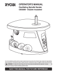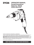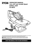
1
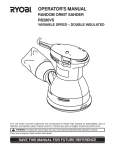
OPERATOR’S MANUAL
BELT/DISC SANDER
MODEL BD4600
6
3
4x
THANK YOU FOR BUYING A RYOBI BENCHTOP BELT/DISC SANDER.
Your new Belt/Disc Sander has been engineered and manufactured to Ryobi's high standards for dependability, ease of
operation, and operator safety. Properly cared for, it will give you years of rugged, trouble-free performance.
CAUTION: Carefully read through this entire operator's manual before using your new machine.
Pay close attention to the Rules for Safe Operation, Warnings, and Cautions. If you use your machine properly and only for
what it is intended, you will enjoy years of safe, reliable service.
Please fill out and return the Warranty Registration Card so we can be of future service to you.
Thank you again for buying Ryobi tools.
SAVE THIS MANUAL FOR FUTURE REFERENCE
1
TABLE OF CONTENTS
■ Product Specifications ......................................................................................................................................................2
■ Rules for Safe Operation .............................................................................................................................................. 3-5
■ Electrical ............................................................................................................................................................................6
■ Unpacking and Loose Parts ..............................................................................................................................................7
■ Features ............................................................................................................................................................................8
■ Assembly ..................................................................................................................................................................... 9-10
■ Adjustments ................................................................................................................................................................... 11
■ Operation .................................................................................................................................................................. 12-13
■ Maintenance .................................................................................................................................................................. 14
■ Parts Ordering/Service .................................................................................................................................................. 16
PRODUCT SPECIFICATIONS
Belt Size
Belt Speed
Belt Tilt
Disc Size
Disc Speed
4 in. (101.6 mm) x 36 in. (914.4 mm)
1900 SF/M
0°-90°
6 in. (152.4 mm)
3600 RPM
Table Size
Table Tilt
Input
Motor
Net Weight
8 1/2 in. x 5 3/4 in. (215.9 mm x 146 mm)
0°-45°
120V AC, 60Hz, 4.3 amps
1/2 HP Induction
53 lbs (24 kg)
Look for this symbol to point out important safety precautions. It
means attention!!! Your safety is involved.
WARNING:
WEAR YOUR
SAFETY
GLASSES
FORESIGHT IS BETTER
THAN NO SIGHT
The operation of any power tool can result in foreign objects being thrown into your eyes, which can
result in severe eye damage. Before beginning tool operation, always wear safety goggles or safety
glasses with side shields and a full face shield when needed. We recommend Wide Vision Safety
Mask for use over eyeglasses or standard safety glasses with side shields. Always wear eye
protection which is marked to comply with ANSI Z87.1.
2
RULES FOR SAFE OPERATION
■ PROTECT YOUR HEARING. Wear hearing protection
during extended periods of operation.
Safe operation of this power tool requires that you read and
understand this operator's manual and all labels affixed to
the tool. Safety is a combination of common sense, staying
alert, and knowing how your tool works.
■ SECURE WORK. Use clamps or a vise to hold the work
when practical. It’s safer than using your hand and frees
both hands to operate the tool.
READ ALL INSTRUCTIONS
■ KNOW YOUR POWER TOOL. Read the operator’s
manual carefully. Learn its applications and limitations as
well as the potential hazards.
■ DO NOT OVERREACH. Keep proper footing and balance
at all times.
■ MAINTAIN TOOLS WITH CARE. Keep tools sharp and
clean for better and safer performance. Follow instructions
for lubricating and changing accessories.
■ GUARD AGAINST ELECTRICAL SHOCK by preventing
body contact with grounded surfaces such as pipes,
radiators, ranges, refrigerator enclosures.
■ DISCONNECT ALL TOOLS. When not in use, before
servicing, or when changing attachments, all tools should
be disconnected.
■ KEEP GUARDS IN PLACE and in good working order.
■ REMOVE ADJUSTING KEYS AND WRENCHES. Get in
the habit - before turning on tool - that hex keys and
adjusting wrenches are removed from tool.
■ AVOID ACCIDENTAL STARTING. Be sure switch is off
when plugging in any tool.
■ KEEP THE WORK AREA CLEAN. Cluttered work areas
and work benches invite accidents. DO NOT leave tools
or pieces of wood on the machine while it is in operation.
■ USE RECOMMENDED ACCESSORIES. Consult this
operator’s manual for recommended accessories. The
use of improper accessories may cause risk of injury.
■ DO NOT USE IN DANGEROUS ENVIRONMENTS. Do
not use power tools near gasoline or other flammable
liquids, in damp or wet locations, or expose them to rain.
Keep the work area well lighted.
■ NEVER STAND ON TOOL. Serious injury could occur if
the tool is tipped or if the sanding belt or disc is
unintentionally contacted.
■ DO NOT FORCE THE TOOL it will do the job better and
safer at the rate for which it was designed.
■ CHECK DAMAGED PARTS. Before using the tool, a
guard or other part that is damaged should be carefully
checked to determine that it will operate properly and
perform its intended function. Check for alignment of
moving parts, binding of moving parts, breakage of parts,
mounting and any other conditions that may affect
operation. A guard or other part that is damaged must be
properly repaired or replaced by an authorized service
center to avoid risk of personal injury.
■ USE THE RIGHT TOOL FOR THE JOB. Do not force the
tool or attachment to do a job for which it was not designed
for. Use it only the way it was intended.
■ NEVER LEAVE TOOL RUNNING UNATTENDED, TURN
THE POWER OFF. Do not leave tool until it comes to a
complete stop.
■ USE THE PROPER EXTENSION CORD. Make sure your
extension cord is in good condition. Use only a cord heavy
enough to carry the current your product will draw. An
undersized cord will cause a drop in line voltage resulting
in loss of power and overheating. A wire gage size
(A.W.G.) of at least 16 is recommended for an extension
cord 25 feet or less in length. If in doubt, use the next
heavier gage. The smaller the gage number, the heavier
the cord.
■ DO NOT ABUSE CORD. Never yank the cord to
disconnect it from the receptacle. Keep the cord from heat,
oil, and sharp edges.
■ KEEP CHILDREN AND VISITORS AWAY. All visitors
should wear safety glasses and be kept a safe distance
from work area. Do not let visitors contact tool or extension
cord while operating.
■ MAKE WORKSHOP CHILDPROOF with padlocks and
master switches or by removing starter keys.
■ KEEP HANDS AWAY FROM WORK AREA. Keep hands
away from the work area. Restrain any loose clothing,
jewelry, long hair, etc. that may become entangled in the
tool.
■ KEEP TOOL DRY, CLEAN, AND FREE FROM OIL AND
GREASE. Always use a clean cloth when cleaning. Never
use brake fluids, gasoline, petroleum-based products, or
any solvents to clean tool.
■ DRESS PROPERLY. Do not wear loose clothing, gloves,
neckties, rings, bracelets, or other jewelry that could get
caught and draw you into moving parts. Non-slip footwear
is recommended. Wear protective covering over long hair.
■ STAY ALERT AND EXERCISE CONTROL. Watch what
you are doing and use common sense. Do not operate
tool when you are tired. Do not rush.
■ ALWAYS WEAR SAFETY GLASSES WITH SIDE
SHIELDS. Everyday eyeglasses have only impact
resistant lenses; they are not safety glasses.
■ DO NOT USE TOOL IF SWITCH DOES NOT TURN IT ON
AND OFF. Have defective switches replaced by an authorized
service center.
■ PROTECT YOUR LUNGS. Wear a face or dust mask if
the operation is dusty.
3
RULES FOR SAFE OPERATION
■ ALWAYS TURN SWITCH OFF before disconnecting it to
avoid accidental starting.
WARNING:
■ ALL REPAIRS, WHETHER ELECTRICAL OR
MECHANICAL, should be made at a Ryobi Authorized
Service Center. Use only Ryobi identical replacement parts.
Some dust created by power sanding, sawing, grinding,
drilling, and other construction activities contains
chemicals known to cause cancer, birth defects or
other reproductive harm. Some examples of these
chemicals are:
• lead from lead-based paints,
• crystalline silica from bricks and cement and other
masonry products, and
• arsenic and chromium from chemically-treated
lumber.
Your risk from these exposures varies, depending on
how often you do this type of work. To reduce your
exposure to these chemicals: work in a well ventilated
area, and work with approved safety equipment, such
as those dust masks that are specially designed to filter
out microscopic particles.
■ SAVE THESE INSTRUCTIONS. Refer to them frequently
and use to instruct other users. If you loan someone this
tool, loan them these instructions also.
SAVE THESE INSTRUCTIONS
The purpose of safety symbols is to attract your attention to possible dangers. The safety symbols, and the
explanations with them, deserve your careful attention and understanding. The safety warnings do not by themselves
eliminate any danger. The instructions or warnings they give are not substitutes for proper accident prevention
measures.
SYMBOL
MEANING
SAFETY ALERT SYMBOL:
Indicates danger, warning, or caution. May be used in conjunction with other symbols or pictographs.
DANGER: Failure to obey a safety warning will result in serious injury to yourself or to others. Always
follow the safety precautions to reduce the risk of fire, electric shock and personal injury.
WARNING: Failure to obey a safety warning can result in serious injury to yourself or to others. Always
follow the safety precautions to reduce the risk of fire, electric shock and personal injury.
CAUTION: Failure to obey a safety warning may result in property damage or personal injury to
yourself or to others. Always follow the safety precautions to reduce the risk of fire, electric shock and
personal injury.
NOTE:
Advises you of information or instructions vital to the operation or maintenance of the equipment.
4
RULES FOR SAFE OPERATION
IMPORTANT
WARNING:
Servicing requires extreme care and knowledge and should
be performed only by a qualified service technician. For
service we suggest you return the tool to your nearest RYOBI
AUTHORIZED SERVICE CENTER for repair. When servicing, use only identical Ryobi replacement parts.
Do not attempt to operate this tool until you have read
thoroughly and understand completely all instructions,
safety rules, etc. contained in this manual. Failure to
comply can result in accidents involving fire, electric
shock, or serious personal injury. Save this operator's
manual and review frequently for continuing safe
operation and instructing others who may use this tool.
WARNING:
Observe all normal safety precautions related to avoiding
electrical shock.
SAFETY AND INTERNATIONAL SYMBOLS
This operator’s manual describes safety and international symbols and pictographs that may appear on this product.
Read the operator’s manual for complete safety, assembly, operating and maintenance, and repair information.
MEANING
Do not expose to rain or use in damp locations
DO NOT reach across the sanding disc to turn the
belt/disc sander ON or OFF. Contact with the sanding
disc can result in serious personal injury.
5
ELECTRICAL
EXTENSION CORDS
ELECTRICAL CONNECTION
Use only 3-wire extension cords that have 3-prong grounding plugs and 3-pole receptacles that accept the tool's plug.
When using a power tool at a considerable distance from the
power source, use an extension cord heavy enough to carry
the current that the tool will draw. An undersized extension
cord will cause a drop in line voltage, resulting in a loss of
power and causing the motor to overheat. Use the chart
provided below to determine the minimum wire size required
in an extension cord. Only round jacketed cords listed by
Underwriter's Laboratories (UL) should be used.
Length of Extension Cord
Wire Size (A.W.G.)
Up to 50 feet
16
When working with the tool outdoors, use an extension cord
that is designed for outside use. This is indicated by the
letters WA on the cord's jacket.
Before using an extension cord, inspect it for loose or
exposed wires and cut or worn insulation. Repair or replace
a damaged or worn cord immediately.
Your Ryobi Belt/Disc Sander is powered by a precision built
electric motor. It should be connected to a power supply
that is 120 volts, 60 Hz. If the machine does not operate
when plugged into an outlet, double check the power supply.
GROUNDING INSTRUCTIONS
In the event of a malfunction or breakdown, grounding
provides a path of least resistance for electric current to
reduce the risk of electric shock. This tool is equipped with an
electric cord having an equipment-grounding conductor and
a grounding plug. The plug must be plugged into a matching
outlet that is properly installed and grounded in accordance
with all local codes and ordinances.
Do not modify the plug provided. If it will not fit the outlet, have
the proper outlet installed by a qualified electrician. Improper
connection of the equipment-grounding conductor can result
in a risk of electric shock. The conductor with insulation
having an outer surface that is green with or without yellow
stripes is the equipment-grounding conductor. If repair or
replacement of the electric cord or plug is necessary, do not
connect the equipment-grounding conductor to a live terminal.
Check with a qualified electrician or service personnel if the
grounding instructions are not completely understood, or if in
doubt as to whether the tool is properly grounded.
Repair or replace a damaged or worn cord immediately.
This tool is intended for use on a circuit that has an outlet like
the one shown in Figure 1. It also has a grounding pin like the
one shown.
CAUTION:
Keep the cord away from the work area and position
the cord so that it will not be caught on material, tools,
or other objects during operation.
GROUNDING
PIN
COVER OF GROUNDED
OUTLET BOX
Fig. 1
6
UNPACKING
Your belt/disc sander has been shipped completely
assembled except for the sanding disc, disc guard, miter
gauge, work support, and worktable.
■ Carefully remove all parts from the shipping carton.
WARNING:
Do not allow familiarity with your belt/disc sander to make
you careless. Remember that a careless fraction of a
second is sufficient to inflict severe injury.
■ Do not discard the packing material until you have carefully
inspected the belt/disc sander, identified all parts, and
satisfactorily operated your new tool.
WARNING:
■ If all parts have been included, proceed to assembly.
■ If any parts are damaged or missing, please call 1-800525-2579 for assistance.
Do not attempt to assemble the belt/disc sander, plug in
the power cord, or turn on switch if any parts are damaged
or missing. Failure to heed this warning could result in
serious personal injury.
■ Examine all parts to make sure no breakage has occurred
during shipping. Any damaged or missing part should be
replaced before attempting to use the tool.
Note: If any parts are damaged or missing, do not attempt
to plug in the power cord and turn the switch on until the
damaged or missing parts are obtained and are installed
correctly.
LOOSE PARTS
Check all loose parts with the list below. Assemble according to the instructions on the following pages.
■
■
■
■
■
■
■
■
■
■
Sanding Disc
Disc Guard
Phillips Screws (2)
Socket Head Screws, M8 x 12 (2)
Washers (2)
Miter Gauge
Hex Key
Worktable
Work Support
Operator’s Manual (not shown)
DISC GUARD
PHILLIPS
SCREWS
SANDING DISC
MITER GAUGE
SOCKET HEAD
SCREWS
WORKTABLE
WORK
SUPPORT
HEX KEY
WASHERS
Fig. 2
7
FEATURES
KNOW YOUR BELT/DISC SANDER
SANDING DISC
See Figure 3.
Before attempting to use your belt/disc sander, familiarize
yourself with all the operating and safety requirements.
A round sanding disc located on the side of the belt/disc
sander.
BEVEL GAUGE
Your disc/belt sander has an easy access power switch. To
lock in the OFF position, remove the switch key. Place the
key in a location inaccessible to children and others not
qualified to use the tool.
SWITCH AND SWITCH KEY
The worktable comes equipped with a bevel gauge that
indicates the degrees the worktable can be tilted up to 45°.
BELT TENSION LEVER
TRACKING KNOB
The belt tension lever releases the belt tension for easy belt
replacement.
A tracking knob aids in centering the sanding belt.
HORIZONTAL AND VERTICAL POSITION HOLES
WORK SUPPORT
The horizontal and vertical position holes are used for
changing the position of the belt from horizontal to vertical.
Supports the workpiece on the sanding belt.
SANDING BELT
Equipped with a sturdy, worktable that provides a stable
surface when using either the disc sanding or the belt sanding
feature.
WORKTABLE
The sanding belt can be adjusted from horizontal to vertical
providing different positions for sanding workpieces of
different shapes and sizes.
WORK
SUPPORT
SANDING
BELT
WORKTABLE
6
3
4x
TRACKING
KNOB
BELT
TENSION
LEVER
SWITCH
AND
SWITCH KEY
SANDING
DISC
HORIZONTAL AND
VERTICAL
POSITION HOLES
BEVEL
GAUGE
Fig. 3
8
ASSEMBLY
INSTALLING SANDING DISC AND DISC GUARD
a
6
3
4x
See Figure 4.
SANDING DISC
WARNING:
DISC GUARD
a
Do not connect to power supply until assembly is complete.
Failure to comply could result in accidental starting and
possible serious injury.
■ Remove the backing from the sanding disc.
■ Align perimeter of sanding disc with plate and press firmly
into position.
■ Position disc guard against the lower one-third of the disc,
aligning holes as shown in figure 4.
■ Using the two phillips head screws, securely tighten the
disc guard into place.
PHILLIPS HEAD
SCREWS
Fig. 4
INSTALLING/REPLACING SANDING BELT
3
4x
See Figure 5.
On the smooth side of the sanding belt, there is a directional
arrow. The sanding belt must run in the direction of the arrow.
■ Pull the tension lever toward you to release belt tension.
■ Place the sanding belt over the drive drum and idler drum
with the directional arrows running counterclockwise. Be
sure the sanding belt is centered on both drums.
■ Push the tension lever back into place to apply the belt
tension.
Note: The tension lever is spring loaded so use extreme
caution when pushing the tension lever back into place to
avoid personal injury.
6
DIRECTIONAL
ARROW
SANDING BELT
Fig. 5
3
4x
MOUNTING THE WORKTABLE FOR USE WITH
THE DISC SANDER
6
WORKTABLE
aa
See Figure 6.
To use the worktable with the disc sander:
■ Insert the index pin into the hole as shown in figure 6.
■ Position the worktable not further than 1/16 in. (1.6 mm)
from the sanding surface.
■ Using a hex key, tighten the hex set screw securely.
HEX SET
SCREW
MOUNTING THE WORKTABLE FOR USE WITH
THE BELT SANDER
See Figure 7.
To use the worktable for vertical sanding:
■ Insert the index pin into the hole as shown in figure 7.
■ Position the worktable not further than 1/16 in. (1.6 mm)
from the sanding surface.
■ Using a hex key, tighten the hex set screw securely.
Fig. 6
WORKTABLE
CAUTION:
To avoid trapping the workpiece or your fingers between
the table and the sanding surface, the table edge should
NEVER be further from the sanding surface than 1/16 in.
(1.6 mm).
HEX SET
SCREW
9
Fig. 7
ASSEMBLY
ASSEMBLING WORK SUPPORT
See Figure 8.
■ Place the work support over the holes in the side of the
tool housing.
■ Using a hex key, fasten in place with the washers and
socket head screws.
WORK
SUPPORT
SOCKET
HEAD
SCREWS
MOUNTING BELT/DISC SANDER TO WORKBENCH
See Figure 9.
If your belt/disc sander is to be used in a permanent location,
it is recommended you secure it to a workbench or other
stable surface. When mounting the belt/disc sander to a
workbench, holes should be drilled through the supporting
surface of the workbench.
■ Mark holes on workbench where belt/disc sander is to be
mounted using holes in the base as a template for hole
pattern.
■ Drill holes through workbench.
■ Place belt/disc sander on workbench aligning holes in the
base with holes drilled in the workbench.
■ Insert bolts (not included) and tighten securely with lock
washers and hex nuts (not included).
Note: All bolts should be inserted from the top. Install the
lock washers and hex nuts from the underside of the
workbench.
WASHERS
Fig. 8
6
3
4x
MOUNTING
BOLTS
MOUNTING
BOLTS
CLAMPING BELT/DISC SANDER TO WORKBENCH
See Figure 10.
If your belt/disc sander is to be used as a portable tool, it is
recommended you fasten it permanently to a mounting board
that can easily be clamped to a workbench or other stable
surface. The mounting board should be of sufficient size to
avoid tipping while belt/disc sander is in use. Any good grade
plywood or chipboard with a 3/4 in. (19 mm) thickness is
recommended.
■ Mark holes on board where belt/disc sander is to be
mounted using holes in the base as a template for hole
pattern.
■ Follow last three steps in section Mounting Belt/Disc
Sander to Workbench.
LOCK
WASHERS
LOCK
WASHERS
HEX NUT
HEX NUT
Fig. 9
36
4x
MOUNTING
BOARD
If lag bolts are used, make sure they are long enough to go
through holes in belt/disc sander base and material the belt/
disc sander is being mounted to. If machine bolts are used,
make sure bolts are long enough to go through holes in belt/
disc sander, the material being mounted to, and the lock
washers and hex nuts.
C-CLAMPS
Fig. 10
10
ADJUSTMENTS
WARNING:
Before performing any adjustment, make sure the belt/
disc sander is unplugged from the power supply and the
switch is in the OFF position. Failure to heed this warning
could result in serious personal injury.
6
3
4x
TRACKING
KNOB
ADJUSTING THE BELT TRACKING
See Figure 11.
■ Plug in belt/disc sander.
SWITCH
To check belt tracking:
■ Turn the switch ON and then immediately turn it OFF. If
the belt tends to slide off the idler drum or drive drum, the
belt is not tracking properly.
Fig. 11
To adjust belt tracking:
■ If the sanding belt moves toward the disc, turn the tracking
knob clockwise 1/4 turn.
■ If the sanding belt moves away from the disc, turn the
tracking knob counterclockwise 1/4 turn.
■ Turn the switch ON and then immediately OFF again,
noting belt movement. Readjust tracking knob if
necessary.
3
4x
6
COMBINATION
SQUARE
SQUARING THE WORKTABLE TO THE
SANDING DISC
See Figure 12.
■ Unplug the belt/disc sander.
■ Using a combination square, check the angle of the
worktable with the sanding belt.
■ If the worktable is not 90° with the disc, loosen the table
lock knob and tilt the table.
■ Adjust worktable square to the sanding disc and retighten
the table lock knob.
Note: Use the adjustment screw beneath the worktable
to move the table further or closer to the sanding disc.
ADJUSTMENT
SCREWS
TABLE
LOCK
KNOB
Fig. 12
WARNING:
Before attempting to use your belt/disc sander familiarize
yourself with all operating features and safety requirements.
6
3
4x
LOCKING THE SWITCH
See Figure 13.
■ Place the switch in the OFF position.
■ Wait until the belt/disc sander has come to a full and
complete stop.
■ Remove the switch key from the switch assembly. Store
key in safe place.
WARNING:
ON/OFF
SWITCH KEY
Do not reach across the sanding disc to turn the belt/disc
sander ON or OFF. Contact with the sanding disc can
result in serious personal injury. See Figure 13.
Fig. 13
11
aaaa
aaa
aa
OPERATION
BEVEL SANDING
1/16 IN OR
LESS
See Figure 14.
The worktable can be tilted from 0° to 45° for bevel sanding.
To tilt the worktable:
■ Loosen the table lock knob by turning it counterclockwise.
■ Set worktable to desired angle.
Note: Position the worktable not further than 1/16 in.
(1.6 mm) from the sanding surface.
■ Tighten the table lock knob by turning it clockwise.
TABLE
LOCK
KNOB
45
0
SANDING SMALL END SURFACES USING THE
MITER GAUGE
15
Fig. 14
aaaaa
See Figure 15.
A miter gauge is included with your tool for increased
accuracy. Use of a miter gauge is recommended for sanding
small end surfaces on the sanding disc.
36
4x
Note: Always move the workpiece across the sanding disc
from the left side towards the right side.
3
4x
HORIZONTAL AND VERTICAL SANDING
See Figure 16.
Your belt/disc sander can sand both vertically and
horizontally. Depending on the workpiece, the work support
can be used with either the horizontal or vertical sanding
operation.
■ Insert the hex key provided into the holes in the pulley
cover. Loosen the screws by turning them counterclockwise.
■ Move the sanding belt into a vertical position as shown
in Figure 16. Vertical position can be changed using the
vertical set screw.
■ Lock the sanding belt by retightening the screws.
Note: Sand long workpieces with the sanding belt in the
vertical position by moving the work evenly across the
sanding belt.
6
MITER GAUGE
Fig. 15
VERTICAL
SET SCREW
VERTICAL
POSITION
HOLE
HORIZONTAL
POSITION
HOLE
Fig. 16
12
OPERATION
SURFACE SANDING ON THE SANDING BELT
See Figure 17.
■ Hold the workpiece firmly, keeping fingers away from the
sanding belt.
■ Keep the end pressed firmly against the work support
moving work evenly across the sanding belt.
Note: Use extra caution when sanding very thin pieces
and when sanding extra long pieces, remove the work
support. Apply only enough pressure to allow the sanding
belt to remove the material.
WORKPIECE
WORK
SUPPORT
6
3
4x
SANDING CURVED PIECES
See Figures 18 and 19.
Fig. 17
WARNING:
Never attempt to sand the end pieces of a workpiece on
the idler drum. Applying the end of the workpiece on the
idler drum could cause the workpiece to fly up. Failure to
heed this warning could result in serious personal injury.
WORKPIECE
Sanding inside curves on sanding belt:
Always sand inside curves on the idler drum as shown in
Figure 18.
■ Hold the workpiece firmly, keeping fingers away from
the sanding belt.
■ Keep the curve pressed firmly against the idler drum
moving work evenly across the sanding belt.
Note: Use extra caution when sanding very thin pieces
and apply only enough pressure to allow the sanding belt
to remove the material.
6
3
4x
IDLER
DRUM
WARNING:
Fig. 18
Applying the workpiece to the right side of the sanding
disc could cause the workpiece kickback. Failure to heed
this warning could result in serious personal injury.
Sanding outside curves on sanding disc:
6
3
4x
Always sand outside curves using the sanding disc and
moving the workpiece from the left side of center as shown
in Figure 19.
■ Hold the workpiece firmly, keeping fingers away from
the sanding disc.
■ Keep the curve pressed firmly against the sanding disc
moving work evenly on the left side of the sanding disc.
WORKPIECE
Fig. 19
13
MAINTENANCE
WARNING:
HEX HEAD
SET SCREW
When servicing use only identical Ryobi replacement
parts. Use of any other parts may create a hazard or cause
product damage.
WARNING:
To avoid serious personal injury make sure the belt/disc
sander is turned OFF and the cord is unplugged from the
power source before performing any maintenance or
adjustment.
SANDING
BELT
GENERAL MAINTENANCE
After using your belt/disc sander, clean it completely and
lubricate all sliding and moving parts. Apply a light coat of
automotive type paste wax to the worktable to help keep the
surfaces clean.
DRIVE
PULLEY
MOTOR HOUSING
Frequently blow out any dust that may accumulate inside
the motor housing.
PHILLIPS HEAD
SCREWS
LUBRICATION
The ball bearings in this tool are permanently lubricated; they
require no further lubrication.
MOTOR
PULLEY
CHANGING DRIVE BELT
DRIVE
BELT
See Figure 20.
■ Using a phillips head screwdriver, remove the two screws
in the center of the pulley cover.
■ Remove the cover.
■ Raise sanding belt to the vertical sanding position (see
Figure 20).
■ Next, loosen the hex head set screw. Raising the motor
pulley releases the belt tension.
■ Remove the old drive belt.
■ Fit the new drive belt on the drive pulley first and then on
the motor pulley.
■ Test belt tension by squeezing the belt with your fingers.
■ Adjust the belt tension with the hex head set screw until
there is about 1/4 in. (6 mm) of give.
■ Tighten the belt tension nut securely.
Note: Excessive tightness on the drive belt may cause
increased noise and overload the motor. Excessive
looseness on the drive belt may cause the drive belt to
fail prematurely and make a severe chattering noise.
■ Using a phillips head screwdriver, reinstall the pulley cover
and the two phillips head screws. Tighten securely.
14
Fig. 20
NOTES
NOTES
15
OPERATOR'S MANUAL
Belt/Disc Sander
Model BD4600
EXTENSION CORD CAUTION
**Ampere rating
When using a power tool at a considerable distance from a power
source, be sure to use an extension cord that has the capacity to
handle the current the tool will draw. An undersized cord will cause
a drop in line voltage, resulting in overheating and loss of power.
Use the chart to determine the minimum wire size required in an
extension cord. Only round jacketed cords should be used.
When working with a tool outdoors, use an extension cord that is
designed for outside use. This is indicated by the letters "WA" on
the cord's jacket.
Before using any extension cord, inspect it for loose or exposed
wires and cut or worn insulation.
(on tool data plate)
0-2.0
Cord Length
25'
50'
100'
16
16
16
2.1-3.4
3.5-5.0
5.1-7.0
7.1-12.0 12.1-16.0
Wire Size (A.W.G.)
16
16
16
16
16
14
16
14
12
14
14
10
14
12
—
CAUTION: Keep the extension cord clear of the working
area. Position the cord so that it will not get caught on workpiece,
tools, or other obstructions while you are working with a power
tool.
**Used on 12 gauge - 20 amp circuit.
• SERVICE
Now that you have purchased your tool, should a need ever exist for repair parts or
service, simply contact your nearest Ryobi Authorized Service Center. Be sure to
provide all pertinent facts when you call or visit. Please call 1-800-525-2579 for your
nearest Ryobi Authorized Service Center. You can also check our web site at
www.ryobitools.com for a complete list of Authorized Service Centers.
• MODEL NO.
The model and serial numbers of your tool will be found on the data plate attached to the
tool. Please record the serial number in the space provided below.
•
MODEL NUMBER
•
SERIAL NUMBER
BD4600
RYOBI TECHNOLOGIES, INC.
1428 Pearman Dairy Road
Anderson, SC 29625
Post Office Box 1207
Anderson SC 29622-1207
Phone 1-800-525-2579
www.ryobitools.com
983000-017
11-02