1
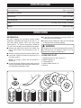
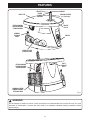
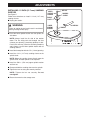
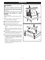
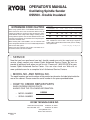
OPERATOR'S MANUAL
Oscillating Spindle Sander
OSS500 - Double Insulated
Your new oscillating spindle sander has been engineered and manufactured to Ryobi's high standard for dependability,
ease of operation, and operator safety. Properly cared for, it will give you years of rugged, trouble-free performance.
WARNING: To reduce the risk of injury, the user must read and understand the operator’s manual.
Thank you for buying a Ryobi oscillating spindle sander.
SAVE THIS MANUAL FOR FUTURE REFERENCE
TABLE OF CONTENTS
■
Introduction ........................................................................................................................................................ 2
■
Rules for Safe Operation ................................................................................................................................3-5
■
Specifications .................................................................................................................................................... 6
■
Unpacking .......................................................................................................................................................... 6
■
Features .........................................................................................................................................................7-8
■
Adjustments .................................................................................................................................................. 9-11
■
Operation ....................................................................................................................................................12-13
■
Maintenance .................................................................................................................................................... 14
■
Parts, Ordering, and Service ........................................................................................................................... 16
INTRODUCTION
Your sander has many features for making sanding
operations more pleasant and enjoyable. Safety,
performance, and dependability have been given top
priority in the design of this tool making it easy to
maintain and operate.
WEAR YOUR
SAFETY
GLASSES
FORESIGHT IS BETTER
THAN NO SIGHT
WARNING:
Do not attempt to use this tool until you have read
thoroughly and understand completely the operator’s
manual. Pay close attention to the safety rules, including Dangers, Warnings, and Cautions. If you
use your sander properly and only for what it is
intended, you will enjoy years of safe, reliable service.
The operation of any power tool can result in foreign objects being thrown into your eyes,
which can result in severe eye damage. Before beginning tool operation, always wear safety
goggles or safety glasses with side shields and a full face shield when needed. We
recommend Wide Vision Safety Mask for use over eyeglasses or standard safety glasses
with side shields. Always wear eye protection which is marked to comply with ANSI Z87.1.
Look for this symbol to point out important safety
precautions. It means attention!!! Your safety is involved.
2
RULES FOR SAFE OPERATION
■ USE OUTDOOR EXTENSION CORDS. When tool is
used outdoors, use only extension cords with approved ground connection that are intended for use
outdoors and so marked.
■ DRESS PROPERLY. Do not wear loose clothing,
gloves, neckties, rings, bracelets, or other jewelry
that can get caught and draw you into moving parts.
Nonslip footwear is recommended. Also wear protective hair covering to contain long hair.
■ ALWAYS WEAR SAFETY GLASSES WITH SIDE
SHIELDS. Everyday eyeglasses have only impactresistant lenses, they are NOT safety glasses.
■ WEAR A DUST MASK to keep from inhaling fine
particles.
■ PROTECT YOUR HEARING. Wear hearing protection during extended periods of operation.
■ INSPECT WORK. Remove all nails from lumber
before sanding.
■ DIRECTION OF FEED. Feed the workpiece into the
sanding sleeve against the direction of the sanding
sleeve rotation only.
■ DO NOT OVERREACH. Keep proper footing and
balance at all times.
■ MAINTAIN TOOLS WITH CARE. Keep tools sharp
and clean for better and safer performance. Follow
instructions for lubricating and changing accessories.
■ DISCONNECT ALL TOOLS when not in use, before
servicing, or when changing attachments.
■ AVOID ACCIDENTAL STARTING. Be sure switch is
off when plugging in any tool.
■ USE RECOMMENDED ACCESSORIES. Using improper accessories may risk injury.
■ MAINTAIN 1/16 in. (1.6 mm) OR LESS between
sanding drum and throat plate.
■ NEVER STAND ON TOOL. Serious injury could
occur if the tool is tipped or if moving parts are
unintentionally contacted.
■ CHECK DAMAGED PARTS. Check any previously
damaged parts for proper operation and performance.
Check alignment of moving parts, binding of moving
parts, breakage of parts, tool stability, mounting and
any other conditions that may affect its operation. A
damaged part must be properly repaired or replaced
by a qualified service technician at an authorized
service center to avoid risk of personal injury.
■ NEVER LEAVE TOOL RUNNING UNATTENDED.
TURN THE POWER OFF. Do not leave tool until it
comes to a complete stop.
■ FIRMLY CLAMP OR BOLT the tool to a workbench or table at approximately hip height.
■ KEEP HANDS AWAY FROM SANDING AREA. Keep
hands away from the sanding sleeve. Do not reach
underneath work or around sanding sleeve while
spindle is rotating.
Safe operation of this power tool requires that you read
and understand this operator's manual and all labels
affixed to the tool. Safety is a combination of common
sense, staying alert, and knowing how your tool works.
READ ALL INSTRUCTIONS
■ KNOW YOUR POWER TOOL. Read the operator's
manual carefully. Learn the tool's applications and
limitations as well as the specific potential hazards
related to this tool.
■ KEEP THROAT PLATES IN PLACE and in working
order.
■ REMOVE WRENCH. Get in the habit of checking to
see that the wrench is removed from the spindle
before turning on the tool. Return the wrench, upper
spindle washer(s), and throat plates to the storage
area when not in use.
■ KEEP WORK AREA CLEAN. Cluttered work areas
and work benches invite accidents. DO NOT leave
tools or pieces of wood on the tool while it is in
operation.
■ DO NOT USE IN DANGEROUS ENVIRONMENTS.
Work in a well lit area. Do not use power tools near
gasoline or other flammable liquids. Do not expose
power tools to rain or damp or wet conditions.
■ KEEP BYSTANDERS AWAY. Keep bystanders,
children, and pets away while operating a power tool.
Distractions can cause you to lose control.
■ MAKE WORKSHOP CHILDPROOF with padlocks
and master switches or by removing starter keys.
■ DO NOT FORCE THE TOOL. It will do the job better
and more safely at the rate for which it was designed.
■ USE THE RIGHT TOOL FOR THE JOB. Do not force
the tool or attachment to do a job for which it was not
designed. Use it only the way it was intended.
■ USE THE PROPER EXTENSION CORD. Make sure
your extension cord is in good condition. Use only a
cord heavy enough to carry the current your product
will draw. An undersized cord will cause a drop in line
voltage resulting in loss of power and overheating. A
wire gage size (A.W.G.) of at least 16 is recommended for an extension cord 25 feet or less in
length. If in doubt, use the next heavier gage. The
smaller the gage number, the heavier the cord.
■ DO NOT ABUSE CORD. Never yank cord to disconnect it from receptacle. Keep cord from heat, oil, and
sharp edges.
■ INSPECT TOOL CORDS AND EXTENSION CORDS
PERIODICALLY and, if damaged, have them repaired by a qualified service technician at an authorized service center. Stay constantly aware of cord
location and keep it well away from the moving parts
of the tool.
3
RULES FOR SAFE OPERATION
■ DO NOT USE TOOL IF SWITCH DOES NOT TURN
IT ON AND OFF. Have defective switches replaced
by a qualified service technician at an authorized
service center.
■ KEEP TOOL DRY, CLEAN, AND FREE FROM OIL
AND GREASE. Always use a clean cloth when
cleaning. Never use brake fluids, gasoline, petroleum-based products, or any solvents to clean tool.
■ REPLACEMENT PARTS. All repairs, whether electrical or mechanical, should be made at your nearest
authorized service center.
■ WHEN SERVICING, use only identical Ryobi replacement parts. Use of any other parts may create
a hazard or cause product damage.
■ NEVER USE THIS TOOL IN AN EXPLOSIVE ATMOSPHERE. Normal sparking of the motor could
ignite fumes.
■ POLARIZED PLUGS. To reduce the risk of electric
shock, this tool has a polarized plug (one blade is
wider than the other). This plug will fit in a polarized outlet only one way. If the plug does not fit
fully in the outlet, reverse the plug. If it still does
not fit, contact a qualified electrician to install the
proper outlet. Do not change the plug in any way.
■ NEVER USE THIS OR ANY POWER SANDER
FOR WET SANDING. Failure to comply can result
in electrical shock causing serious injury.
■ DO NOT OPERATE THIS TOOL WHILE UNDER
THE INFLUENCE OF DRUGS, ALCOHOL, OR
ANY MEDICATION.
■ STAY ALERT AND EXERCISE CONTROL. Watch
what you are doing and use common sense. Do not
operate tool when you are tired. Do not rush.
■ ALWAYS TURN OFF THE TOOL before disconnecting it to avoid accidental starting when reconnecting
to power supply. NEVER leave the tool unattended
while connected to a power source.
■ SAVE THESE INSTRUCTIONS. Refer to them frequently and use them to instruct other users. If you
loan someone this tool, loan them these instructions
also.
WARNING:
Some dust created by power sanding, sawing,
grinding, drilling, and other construction activities
contains chemicals known to cause cancer, birth
defects or other reproductive harm. Some examples
of these chemicals are:
• lead from lead-based paints,
• crystalline silica from bricks and cement
and other masonry products, and
• arsenic and chromium from chemicallytreated lumber.
Your risk from these exposures varies, depending
on how often you do this type of work. To reduce
your exposure to these chemicals: work in a well
ventilated area, and work with approved safety
equipment, such as those dust masks that are
specially designed to filter out microscopic particles.
4
RULES FOR SAFE OPERATION
The purpose of safety symbols is to attract your attention to possible dangers. The safety symbols, and the
explanations with them, deserve your careful attention and understanding. The safety warnings do not by
themselves eliminate any danger. The instructions or warnings they give are not substitutes for proper accident
prevention measures.
SYMBOL
MEANING
DANGER: Failure to obey a safety warning will result in serious injury to yourself or to others.
Always follow the safety precautions to reduce the risk of fire, electric shock and personal injury.
WARNING: Failure to obey a safety warning can result in serious injury to yourself or to others.
Always follow the safety precautions to reduce the risk of fire, electric shock and personal injury.
CAUTION: Failure to obey a safety warning may result in property damage or personal injury to
yourself or to others. Always follow the safety precautions to reduce the risk of fire, electric shock
and personal injury.
WET CONDITIONS ALERT: Do not expose to rain or use in damp locations.
NOTE: Advises you of information or instructions vital to the operation or maintenance of the
equipment.
SAVE THESE INSTRUCTIONS
DOUBLE INSULATION
ELECTRICAL CONNECTION
Double insulation is a concept in safety in electric power
tools, which eliminates the need for the usual three-wire
grounded power cord. All exposed metal parts are
isolated from the internal metal motor components with
protecting insulation. Double insulated tools do not need
to be grounded.
Your tool has a precision built electric motor. It should
be connected to a power supply that is 120 volts, 60
Hz, AC only (normal household current). Do not
operate this tool on direct current (DC). A substantial
voltage drop will cause a loss of power and the motor will
overheat. If your tool does not operate when plugged
into an outlet, double-check the power supply.
WARNING:
The double insulated system is intended to protect
the user from shock resulting from a break in the
tool’s internal wiring. Observe all normal safety precautions to avoid electrical shock.
Important: Servicing of a tool with double insulation
requires extreme care and knowledge of the system and
should be performed only by a qualified service
technician. For service, we suggest you return the tool to
your nearest authorized service center for repair. Always
use original factory replacement parts when servicing.
5
SPECIFICATIONS
Oscillating Range
5/8 in. (15.9 mm)
Oscillations Per Minute
58 OPM
Spindle Size
1/2 in. (12.7 mm)
No Load Speed
2000 RPM
Input
120 Volts, 60 Hz, AC only, 3.5 Amps
Weight
49 lbs. (22.2 kg)
UNPACKING
■ If any parts are damaged or missing, please call
1-800-525-2579 for assistance.
■ Inspect all parts carefully to make sure no breakage
or damage occurred during shipping.
INFORMATION
We have shipped the oscillating spindle sander
completely assembled and ready to use with a 1 in.
(25.4 mm) rubber spindle, 7/8 in. (22.2 mm) upper
spindle washer, 1 in. (26 mm) throat plate, and 80 grit
1 in. (25.4 mm) sanding sleeve installed on the spindle.
■ Remove the loose parts from the box. Make sure
that all items listed in the loose parts list are included.
■ Remove the packing materials from around the tool.
■ Lift the tool carefully from the box and place it on a
level work surface.
WARNING:
If any parts are missing do not operate the tool until
the missing parts are replaced. Failure to do so
could result in serious personal injury.
LOOSE PARTS LIST
1. Sanding sleeves, 50, 80, 150 grit (17)
2. Rubber spindles (4)
3. Throat plates (5)
4. Upper spindle washers (2)
5. Wrench
NOTE: The sander is heavy. Ask for assistance if
necessary.
■ Do not discard the packing material until you have
carefully inspected the tool, identified all loose parts,
and satisfactorily operated the tool.
3
5
4
1
2
6
FEATURES
Before using the oscillating spindle sander, familiarize
yourself with all operating features and safety
requirements. However, do not let familiarity with the tool
make you careless.
TABLE SIZE
The sanding table provides ample sanding space for
most workpieces. The table top is 19-1/4 in. (489 mm)
long x 15-3/4 in. (400 mm) wide.
WARNING:
THROAT PLATES
Six throat plates are included with the sander. The throat
plate provides a stable surface around the sanding
sleeve and prevents objects from falling through the
throat and damaging the spindle.
Exercise caution when using the oscillating spindle
sander. Careless actions, for even a fraction of a
second, can result in serious personal injury.
SWITCH
DUST COLLECTION
The ON/OFF switch has a built-in locking feature that
requires you to insert a key before turning on the sander.
Pushing the switch to the OFF position and removing the
key secures the sander against unintentional use. This
feature is intended to prevent unauthorized and possible
hazardous use by children and others.
A standard 2-1/4 in. (57.2 mm) dust exhaust port is
provided to help keep dust to a minimum. It is located
under the table top on the back of the sander. The end
of a standard shop vacuum hose fits tightly inside the
dust exhaust port.
THROAT PLATE/WRENCH STORAGE AREA
WARNING:
A throat plate and wrench storage area is located on the
left side of the cabinet.
Always lock the switch OFF when the sander is not
in use. Remove the key and keep it in a safe place.
In the event of a power failure, turn the switch OFF
and remove the key. This action will prevent the
sander from accidentally starting when power returns.
SANDING SLEEVE/RUBBER SPINDLE
STORAGE AREA
A sanding sleeve and rubber spindle storage area is
located on the right side of the cabinet. Store unused
sanding sleeves and rubber spindles on their designated
pins. Proper storage of sanding sleeves and rubber
spindles helps protect them from being damaged and
getting lost.
MOTOR
The sander has a 3.5 amp motor with sufficient power to
handle tough sanding jobs. It develops a no load speed
of 2,000 RPM and 58 OPM.
EXTRA SANDING
STORAGE AREA
OSCILLATING MOTION
SLEEVE/WASHER
Store extra sanding sleeves and upper spindle washers
under the table in either of the cavities.
As the name implies, the most unique feature of this
sander is the fact that it oscillates. This means that the
spindle rises and falls as it rotates. The oscillating range
for the sander is 5/8 in. (15.9 mm).
SANDING CAPACITIES
The sander accepts sanding sleeves that are 1/2 in.
(12.7 mm) through 3 in. (76.2 mm) in diameter and
4-1/2 in. (114.3 mm) in height.
NOTE: Sanding sleeves are 4-1/2 in. (114.3 mm) tall;
however, you can only sand material up to 3-11/16 in.
(93.7 mm) thick.
The 1/2 in. (12.7 mm) sanding sleeve fits directly on the
1/2 in. (12.7 mm) spindle and requires no rubber spindle.
It is secured in place with a washer and hex nut on top
of the spindle. All other sanding sleeves require a rubber
spindle to secure them in place. These rubber spindles
fit on the spindle and require a throat plate and sanding
sleeve. A washer and hex nut thread on top of the spindle
to hold everything in place.
7
FEATURES
HEX NUT
TABLE TOP
SPINDLE
UPPER
SPINDLE
WASHER
SANDING SLEEVE
(1 in. (25.4 mm))
EXTRA SANDING
SLEEVE/WASHER
STORAGE AREA
THROAT
PLATE
WRENCH
STORAGE
AREA
SWITCH
THROAT PLATE
STORAGE AREA
DUST
EXHAUST
PORT
EXTRA SANDING
SLEEVE/WASHER
STORAGE AREA
SANDING SLEEVE/
RUBBER SPINDLE
STORAGE AREA
Fig. 1
WARNING:
Do not attempt to modify this tool or create accessories not recommended for use with this tool. Any such
alteration or modification is misuse and could result in a hazardous condition leading to possible serious
personal injury.
8
ADJUSTMENTS
SELECTING THROAT PLATES/UPPER
SPINDLE WASHERS
WARNING:
The sander should never be connected to a power
supply when you are assembling parts, making adjustments, cleaning, or when not in use. Disconnecting the tool will prevent accidental starting that could
cause serious personal injury.
See Figure 2.
Six throat plates are provided with this sander. Each
throat plate indicates the correct sanding sleeve/rubber
spindle size to use.
The chart below identifies the relationship between
sanding sleeves/rubber spindles, throat plates, and upper
spindle washers.
SELECTING SANDING SLEEVES
Selecting the correct size diameter, correct size grit, and
correct type sanding sleeve is an extremely important
step in achieving a high quality sanded finish. Aluminum
oxide, silicon carbide, and other synthetic abrasives are
best for power sanding. Natural abrasives, such as flint
and garnet are too soft for power sanding.
In general, when sanding, coarse grit removes the most
material and fine grit produces the best finish. The
condition of the surface to be sanded determines which
grit will do the best job. If the surface is rough, start with
a coarse grit and sand until the surface is uniform. Then
use medium grit to remove scratches left by the coarser
grit. Finally, use finer grit for finishing the surface. Always
continue sanding with each grit until the surface is
uniform.
NOTE: Do not use the sander without a sanding sleeve.
Doing so will damage the rubber spindle.
Select and install the desired sanding sleeve for your
particular application. As mentioned previously, you can
use sanding sleeves from 1/2 in. (12.7 mm) to 3 in.
(76.2 mm) in diameter with this sander. Choose one that
is close in size to the workpiece you are sanding.
WARNING:
Failure to use the correct size throat plate with its
matching sanding sleeve could result in fingers being
pinched or the workpiece being pulled down between
the throat plate and the sanding sleeve.
SANDING
SLEEVE
THROAT
PLATE
THROAT
PLATE
OPENING
Fig. 2
Sanding Sleeve/Rubber Spindle
Throat Plate
Upper Spindle Washer
1/2 in. (12.7 mm)
.5” (13 mm)
5/8 in. (15.9 mm)
3/4 in. (19.1 mm)
.75” (19 mm)
7/8 in. (22.2 mm)
1 in. (25.4 mm)
1” (26 mm)
7/8 in. (22.2 mm)
1-1/2 in. (38.1 mm)
1.5” (38 mm)
7/8 in. (22.2 mm)
2 in. (50.8 mm)
2” (51 mm)
1-13/16 in. (46 mm)
3 in. (76.2 mm)
3” (76 mm)
1-13/16 in. (46 mm)
9
ADJUSTMENTS
REMOVING SANDING SLEEVES
See Figure 3.
Follow these directions to remove sanding sleeves.
■ Unplug the sander.
WRENCH
TO LOOSEN
WARNING:
Failure to unplug the tool could result in accidental
starting causing serious injury.
SANDING
SLEEVE
■ Grasp and hold the sanding sleeve on the spindle.
THROAT
PLATE
■ Loosen the hex nut using the wrench provided.
TO TIGHTEN
NOTE: If the hex nut is too tight and the spindle shaft
spins inside the sanding sleeve, grasp the flats on
top of the spindle shaft with a 1/4 in. wrench (not
provided) and loosen the hex nut.
■ Remove the hex nut, upper spindle washer, sanding
sleeve, rubber spindle, and throat plate.
Fig. 3
HEX NUT
NOTE: It is recommended that you clean dust
accumulations from the throat plate, throat plate nest,
and under the lower spindle washer after each use.
Remove the lower spindle washer and clean dust
accumulations.
THROAT
PLATE
UPPER
SPINDLE
WASHER
SANDING
SLEEVE
RUBBER
SPINDLE
INSTALLING SANDING SLEEVES
(All except 1/2 in. (12.7 mm))
See Figure 4.
Follow these directions to install sanding sleeves.
■ Unplug the sander.
LOWER
SPINDLE
WASHER
WRENCH
SPINDLE
WARNING:
Failure to unplug the tool could result in accidental
starting causing serious injury.
■ Place the lower spindle washer over the spindle, fin
side down.
Fig. 4
NOTE: Always install the fin side of the washer
down. The fins help push dust through the dust
exhaust port opening, preventing buildup of dust.
Dust in this area may cause the oscillating motion to
stop. Always use the lower spindle washer with all
sanding sleeves.
■ Install the upper spindle washer and hex nut.
NOTE: Use the 7/8 in. (22.2 mm) washer for the 3/4
in. (19.1 mm), 1 in. (25.4 mm), and 1-1/2 in.
(38.1 mm) rubber spindles. Use the 1-13/16 in.
(46 mm) washer for the 2 in. (50.8 mm) and 3 in.
(76.2 mm) rubber spindles.
■ Select and install the correct throat plate. Refer to
SELECTING THROAT PLATES/UPPER SPINDLE
WASHERS earlier in this manual.
■ Select and install the correct rubber spindle.
■ Install the appropriate sanding sleeve on the rubber
spindle.
■ Grasp and hold the sanding sleeve on the spindle.
■ Tighten the hex nut using the wrench provided.
NOTE: Tighten the hex nut only enough to expand
the rubber spindle against the inner wall of the
sanding sleeve. Do not overtighten.
NOTE: If the sanding sleeve becomes difficult to
remove or install, apply talcum powder on the rubber
spindle or inside the sanding sleeve before installing
the sanding sleeve on the rubber spindle.
■ Return the wrench to the storage area.
10
ADJUSTMENTS
INSTALLING 1/2 INCH (12.7 mm) SANDING
SLEEVES
UPPER
SPINDLE
WASHER
See Figure 5.
Follow these directions to install 1/2 inch (12.7 mm)
sanding sleeves.
HEX NUT
SANDING
SLEEVE
THROAT
PLATE
■ Unplug the sander.
WARNING:
LOWER
SPINDLE
WASHER
Failure to unplug the tool could result in accidental
starting causing serious injury.
WRENCH
SPINDLE
■ Place the lower spindle washer over the spindle, fin
side down.
NOTE: Always install the fin side of the washer
down. The fins help push dust through the dust
exhaust port opening, preventing buildup of dust.
Dust in this area may cause the oscillating motion to
stop. Always use the lower spindle washer with all
sanding sleeves.
Fig. 5
■ Install the throat plate with the .5 in. (13 mm) opening.
■ Install the 1/2 in. (12.7 mm) sanding sleeve on the
spindle shaft.
NOTE: Mount the sanding sleeve directly onto the
spindle shaft. A rubber spindle is not required.
■ Install the 5/8 in. (15.9 mm) upper spindle washer
and hex nut.
■ Grasp and hold the sanding sleeve on the spindle.
■ Tighten the hex nut using the wrench provided.
NOTE: Tighten the hex nut securely. Do not
overtighten.
■ Return the wrench to the storage area.
11
OPERATION
WARNING:
Always wear safety goggles or safety glasses with
side shields when operating this tool. Failure to do
so could result in dust, shavings, or loose particles
being thrown into your eyes, resulting in possible
serious injury.
MOUNTING THE SANDER TO A WORK
SURFACE
See Figures 6 and 7.
Follow these directions to mount the sander to a work
surface.
■ Place the sander on a sturdy work surface, e.g.,
work stand, workbench, counter top.
■ Mark the holes in the sander base with a pencil.
■ Remove the sander from the work surface.
Fig. 6
■ Drill three holes through the work surface.
■ Place the sander back on the work surface, aligning
the holes in the base with the holes in the work
surface.
NOTE: If the sander does not appear to be stable,
make sure the rubber stabilizers are intact on the
sander bottom.
■ Insert three bolts (not included, 1/4 in. (6.4 mm)
machine bolts recommended) and tighten securely
with lock washers and hex nuts (not included).
■ Check the work surface carefully after you mount
the sander to make sure that no movement can
occur during use. If you notice any tipping, sliding,
or walking, secure the work surface to the floor
before operating the tool.
Fig. 7
NOTE: If you plan to transport the sander to different
locations, we recommend that you attach it
permanently to a mounting board that you can easily
clamp to a work surface.
12
OPERATION
OPERATING THE SANDER
See Figures 8 and 9.
Follow these directions to operate the sander.
SWITCH KEY
■ Insert the switch key.
■ Turn on the sander by lifting the switch.
■ Let the motor build to its full speed.
■ Feed the workpiece gradually against the sanding
sleeve from right to left.
WARNING:
Do not let the workpiece contact the sanding sleeve
before you turn on the sander and allow it to develop
full speed.
SWITCH
Fig. 8
WARNING:
When you feed the workpiece from right to left, the
rotation of the sanding sleeve sands against the
workpiece. If you feed the workpiece in the opposite
direction, the rotation forces of the spinning sanding
sleeve tends to bounce the workpiece away from the
sanding sleeve. This action could cause you to lose
control of the workpiece.
COLLECTING DUST
See Figure 10.
A dust exhaust port is provided to help keep dust to a
minimum. It is located under the table top on the back of
the sander. The end of a standard shop vacuum hose fits
tightly inside the dust exhaust port.
Even with a dust collection system, it is important to
periodically clean sanding dust from the throat plate
area. After extended use, sanding dust builds up under
the throat plate and forces its way into the throat plate
nest. Sanding dust build up in this area may cause the
throat plate surface to rise above the table surface.
Fig. 9
TRANSPORTING THE SANDER
In a portable application, you can lift and carry the
sander by the table top. When carrying the sander, be
careful not to dislodge the throat plates, wrench, and
upper spindle washers from their respective storage
areas. Also, be careful not to lose any parts when
transporting.
Fig. 10
13
MAINTENANCE
WARNING:
When servicing use only identical Ryobi replacement parts. Use of any other parts may create a hazard or cause
product damage.
GENERAL
WARNING:
Avoid using solvents when cleaning plastic parts. Most
plastics are susceptible to damage from various types of
commercial solvents and may be damaged by their use.
Use clean cloths to remove dirt, carbon dust, etc.
Always wear safety goggles or safety glasses with
side shields during power tool operation or when
blowing dust. If operation is dusty, also wear a dust
mask.
WARNING:
LUBRICATION
Do not at any time let brake fluids, gasoline, petroleum-based products, penetrating oils, etc. come in
contact with plastic parts. They contain chemicals
that can damage, weaken, or destroy plastic.
All the bearings in this tool are lubricated with a sufficient
amount of high grade lubricant for the life of the unit
under normal operating conditions. Therefore, no further
lubrication is required.
Electric tools used on fiberglass material, wallboard,
spackling compounds, or plaster are subject to
accelerated wear and possible premature failure, as the
fiberglass chips and grindings are highly abrasive to
bearings, brushes, commutators, etc. Consequently, we
do not recommend that this tool be used for extended
work on these types of materials. If, however, you do
work with any of these materials, it is extremely important
that you clean the tool frequently by blowing it with an air
jet.
NOTE: Only use this sander for sanding wood and
plastics.
14
NOTES
15
OPERATOR'S MANUAL
Oscillating Spindle Sander
OSS500 - Double Insulated
EXTENSION CORD CAUTION
When using a power tool at a considerable distance from a
power source, be sure to use an extension cord that has the
capacity to handle the current the tool will draw. An undersized cord will cause a drop in line voltage, resulting in overheating and loss of power. Use the chart to determine the minimum wire size required in an extension cord. Only round jacketed cords should be used.
When working with a tool outdoors, use an extension cord
that is designed for outside use. This is indicated by the letters
"WA" on the cord's jacket.
**Ampere rating
(on tool faceplate)
0-2.0
Cord Length
2.1-3.4
3.5-5.0
5.1-7.0
7.1-12.0 12.1-16.0
Wire Size (A.W.G.)
25'
16
16
16
16
14
14
50'
16
16
16
14
14
12
CAUTION: Keep the extension cord clear of the working
area. Position the cord so that it will not get caught on
lumber, tools or other obstructions while you are working
with a power tool.
**Used on 12 gauge - 20 amp circuit.
Before using any extension cord, inspect it for loose or exposed wires and cut or worn insulation.
• SERVICE
Now that you have purchased your tool, should a need ever exist for repair parts or
service, simply contact your nearest Ryobi Authorized Service Center. Be sure to
provide all pertinent facts when you call or visit. Please call 1-800-525-2579 for your
nearest Ryobi Authorized Service Center. You can also check our Web site at
www.ryobitools.com for a complete list of Authorized Service Centers.
• MODEL NO. AND SERIAL NO.
The model number and serial number of this product are found on the label attached to the
rear of the cabinet. Please record the serial number in the space provided below.
• HOW TO ORDER REPAIR PARTS
WHEN ORDERING REPAIR PARTS,
ALWAYS GIVE THE FOLLOWING INFORMATION:
•
MODEL NUMBER
•
SERIAL NUMBER
OSS500
RYOBI TECHNOLOGIES INC.
1428 Pearman Dairy Road
Anderson, SC 29625
Post Office Box 1207
Anderson, SC 29622
www.ryobitools.com
Phone 1-800-525-2579
983000-146
9-02