1
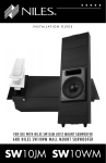
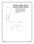
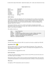
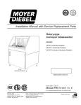
IMPULSE Non-Carbonated Post-Mix Beverage Dispenser Installation & Operation Manual Release Date: December 16, 2003 Publication Number: 859000159INS Revision Date: June 01, 2012 Revision: B Visit the IMI Cornelius web site at www.cornelius.com for all your Literature needs. The products, technical information, and instructions contained in this manual are subject to change without notice. These instructions are not intended to cover all details or variations of the equipment, nor to provide for every possible contingency in the installation, operation or maintenance of this equipment. This manual assumes that the person(s) working on the equipment have been trained and are skilled in working with electrical, plumbing, pneumatic, and mechanical equipment. It is assumed that appropriate safety precautions are taken and that all local safety and construction requirements are being met, in addition to the information contained in this manual. This Product is warranted only as provided in Cornelius’ Commercial Warrant applicable to this Product and is subject to all of the restrictions and limitations contained in the Commercial Warranty. Cornelius will not be responsible for any repair, replacement or other service required by or loss or damage resulting from any of the following occurrences, including but not limited to, (1) other than normal and proper use and normal service conditions with respect to the Product, (2) improper voltage, (3) inadequate wiring, (4) abuse, (5) accident, (6) alteration, (7) misuse, (8) neglect, (9) unauthorized repair or the failure to utilize suitably qualified and trained persons to perform service and/or repair of the Product, (10) improper cleaning, (11) failure to follow installation, operating, cleaning or maintenance instructions, (12) use of “non-authorized” parts (i.e., parts that are not 100% compatible with the Product) which use voids the entire warranty, (13) Product parts in contact with water or the product dispensed which are adversely impacted by changes in liquid scale or chemical composition. Contact Information: To inquire about current revisions of this and other documentation or for assistance with any Cornelius product contact: www.cornelius.com 800-238-3600 Trademarks and Copyrights: This document contains proprietary information and it may not be reproduced in any way without permission from Cornelius. This document contains the original instructions for the unit described. IMI CORNELIUS INC 101 Regency Drive Glendale Heights, IL Tel: + 1 800-238-3600 Printed in U.S.A. TABLE OF CONTENTS Safety Instructions . . . . . . . . . . . . . . . . . . . . . . . . . . . . . . . . . . . . . . . . . . . . . . . . . . . . . . . . . . . . . . . . . 1 Read and Follow ALL Safety Instructions . . . . . . . . . . . . . . . . . . . . . . . . . . . . . . . . . . . . . . . . . . . . . 1 Safety Overview . . . . . . . . . . . . . . . . . . . . . . . . . . . . . . . . . . . . . . . . . . . . . . . . . . . . . . . . . . . . . . 1 Recognition . . . . . . . . . . . . . . . . . . . . . . . . . . . . . . . . . . . . . . . . . . . . . . . . . . . . . . . . . . . . . . . . . 1 Different Types of Alerts . . . . . . . . . . . . . . . . . . . . . . . . . . . . . . . . . . . . . . . . . . . . . . . . . . . . . . . . . . 1 Safety Tips . . . . . . . . . . . . . . . . . . . . . . . . . . . . . . . . . . . . . . . . . . . . . . . . . . . . . . . . . . . . . . . . . . . . . 1 Qualified Service Personnel . . . . . . . . . . . . . . . . . . . . . . . . . . . . . . . . . . . . . . . . . . . . . . . . . . . . . . . . 1 Safety Precautions . . . . . . . . . . . . . . . . . . . . . . . . . . . . . . . . . . . . . . . . . . . . . . . . . . . . . . . . . . . . . . . 2 Shipping And Storage . . . . . . . . . . . . . . . . . . . . . . . . . . . . . . . . . . . . . . . . . . . . . . . . . . . . . . . . . . . . 2 Mounting in or on a Counter . . . . . . . . . . . . . . . . . . . . . . . . . . . . . . . . . . . . . . . . . . . . . . . . . . . . . . . 2 CO2 (Carbon Dioxide) Warning . . . . . . . . . . . . . . . . . . . . . . . . . . . . . . . . . . . . . . . . . . . . . . . . . . . . . 2 Installation . . . . . . . . . . . . . . . . . . . . . . . . . . . . . . . . . . . . . . . . . . . . . . . . . . . . . . . . . . . . . . . . . . . . . . . 3 Installation Requirements . . . . . . . . . . . . . . . . . . . . . . . . . . . . . . . . . . . . . . . . . . . . . . . . . . . . . . . . . 3 Requirements Summary . . . . . . . . . . . . . . . . . . . . . . . . . . . . . . . . . . . . . . . . . . . . . . . . . . . . . . . 3 Electrical Requirements . . . . . . . . . . . . . . . . . . . . . . . . . . . . . . . . . . . . . . . . . . . . . . . . . . . . . . . . . . . 3 Installation Procedure . . . . . . . . . . . . . . . . . . . . . . . . . . . . . . . . . . . . . . . . . . . . . . . . . . . . . . . . . . . . . . 4 Counter-top Installation . . . . . . . . . . . . . . . . . . . . . . . . . . . . . . . . . . . . . . . . . . . . . . . . . . . . . . . . . . . 4 Connect Concentrate and Water Lines . . . . . . . . . . . . . . . . . . . . . . . . . . . . . . . . . . . . . . . . . . . . . . . 5 Adjust Water-to-Concentrate Ratio . . . . . . . . . . . . . . . . . . . . . . . . . . . . . . . . . . . . . . . . . . . . . . . . . . 6 Adjusting Flow Rates . . . . . . . . . . . . . . . . . . . . . . . . . . . . . . . . . . . . . . . . . . . . . . . . . . . . . . . . . . . . . 6 Operations . . . . . . . . . . . . . . . . . . . . . . . . . . . . . . . . . . . . . . . . . . . . . . . . . . . . . . . . . . . . . . . . . . . . . . . 7 Starting and Stopping the Unit . . . . . . . . . . . . . . . . . . . . . . . . . . . . . . . . . . . . . . . . . . . . . . . . . . . . . . 7 Dispensing Product . . . . . . . . . . . . . . . . . . . . . . . . . . . . . . . . . . . . . . . . . . . . . . . . . . . . . . . . . . . . . . 7 Replenishing Concentrate Supply . . . . . . . . . . . . . . . . . . . . . . . . . . . . . . . . . . . . . . . . . . . . . . . . . . . 7 Adjustments . . . . . . . . . . . . . . . . . . . . . . . . . . . . . . . . . . . . . . . . . . . . . . . . . . . . . . . . . . . . . . . . . . . . 7 Water-to-Concentrate Ratio Adjustment . . . . . . . . . . . . . . . . . . . . . . . . . . . . . . . . . . . . . . . . . . . . . . 7 Cleaning & Checks . . . . . . . . . . . . . . . . . . . . . . . . . . . . . . . . . . . . . . . . . . . . . . . . . . . . . . . . . . . . . . 8 Daily Cleaning . . . . . . . . . . . . . . . . . . . . . . . . . . . . . . . . . . . . . . . . . . . . . . . . . . . . . . . . . . . . . . . 8 Daily Checks . . . . . . . . . . . . . . . . . . . . . . . . . . . . . . . . . . . . . . . . . . . . . . . . . . . . . . . . . . . . . . . . 8 Sanitizing Concentrate Systems . . . . . . . . . . . . . . . . . . . . . . . . . . . . . . . . . . . . . . . . . . . . . . . . . . . . 8 Reference Material . . . . . . . . . . . . . . . . . . . . . . . . . . . . . . . . . . . . . . . . . . . . . . . . . . . . . . . . . . . . . . . . 10 Troubleshooting . . . . . . . . . . . . . . . . . . . . . . . . . . . . . . . . . . . . . . . . . . . . . . . . . . . . . . . . . . . . . . . . . . 13 Non-Carbonated Impulse Installation & Operations Manual SAFETY INSTRUCTIONS READ AND FOLLOW ALL SAFETY INSTRUCTIONS Safety Overview • Read and follow ALL SAFETY INSTRUCTIONS in this manual and any warning/caution labels on the unit (decals, labels or laminated cards). • Read and understand ALL applicable OSHA (Occupational Safety and Health Administration) safety regulations before operating this unit. Recognition Recognize Safety Alerts ! This is the safety alert symbol. When you see it in this manual or on the unit, be alert to the potential of personal injury or damage to the unit. DIFFERENT TYPES OF ALERTS ! DANGER: Indicates an immediate hazardous situation which if not avoided WILL result in serious injury, death or equipment damage. ! WARNING: Indicates a potentially hazardous situation which, if not avoided, COULD result in serious injury, death, or equipment damage. ! CAUTION: Indicates a potentially hazardous situation which, if not avoided, MAY result in minor or moderate injury or equipment damage. SAFETY TIPS • Carefully read and follow all safety messages in this manual and safety signs on the unit. • Keep safety signs in good condition and replace missing or damaged items. • Learn how to operate the unit and how to use the controls properly. • Do not let anyone operate the unit without proper training. This appliance is not intended for use by very young children or infirm persons without supervision. Young children should be supervised to ensure that they do not play with the appliance. • Keep your unit in proper working condition and do not allow unauthorized modifications to the unit. QUALIFIED SERVICE PERSONNEL ! WARNING: Only trained and certified electrical, plumbing and refrigeration technicians should service this unit. ALL WIRING AND PLUMBING MUST CONFORM TO NATIONAL AND LOCAL CODES. FAILURE TO COMPLY COULD RESULT IN SERIOUS INJURY, DEATH OR EQUIPMENT DAMAGE. Publication Number: 859000159INS -1- © 2003-2012, IMI Cornelius Inc. Non-Carbonated Impulse Installation & Operational Manual SAFETY PRECAUTIONS This unit has been specifically designed to provide protection against personal injury. To ensure continued protection observe the following: ! WARNING: Disconnect power to the unit before servicing following all lock out/tag out procedures established by the user. Verify all of the power is off to the unit before any work is performed. Failure to disconnect the power could result in serious injury, death or equipment damage. ! CAUTION: Always be sure to keep area around the unit clean and free of clutter. Failure to keep this area clean may result in injury or equipment damage. SHIPPING AND STORAGE ! CAUTION: Before shipping, storing, or relocating the unit, the unit must be sanitized and all sanitizing solution must be drained from the system. A freezing ambient environment will cause residual sanitizing solution or water remaining inside the unit to freeze resulting in damage to internal components. MOUNTING IN OR ON A COUNTER ! WARNING: When installing the unit in or on a counter top, the counter must be able to support a weight in excess of 430 lbs. to insure adequate support for the unit. FAILURE TO COMPLY COULD RESULT IN SERIOUS INJURY, DEATH OR EQUIPMENT DAMAGE. NOTE: Many units incorporate the use of additional equipment such as icemakers. When any addition equipment is used you must check with the equipment manufacturer to determine the additional weight the counter will need to support to ensure a safe installation. CO2 (CARBON DIOXIDE) WARNING ! DANGER: CO2 displaces oxygen. Strict attention MUST be observed in the prevention of CO2 gas leaks in the entire CO2 and soft drink system. If a CO2 gas leak is suspected, particularly in a small area, IMMEDIATELY ventilate the contaminated area before attempting to repair the leak. Personnel exposed to high concentrations of CO2 gas experience tremors which are followed rapidly by loss of consciousness and DEATH. © 2003-2012, IMI Cornelius Inc. -2- Publication Number: 859000159INS Non-Carbonated Impulse Installation & Operations Manual INSTALLATION ! WARNING: It is the responsibility of the installer to ensure that the water supply to the dispensing equipment is provided with protection back flow by an air gap as defined in ANSI A 112.1.2-1979; or an approved vacuum breaker or other such method as proved effective by test and must comply with all federal, state and local codes. Failure to comply could result in serious injury, death or damage to the equipment. Water pipe connections and fixtures directly connected to a potable water supply shall be sized, installed and maintained according to Federal, State and Local laws. INSTALLATION REQUIREMENTS Requirements Summary Weight Front or rear counter must be level and able to support 400 lbs Environment Indoor Installation only Temperature 40° To 110° F Ambient Temperature Clearance 18-Inches above 6-Inches on Sides and Rear CO2: 75 Psi (5.25 Bar) At Unit With Internal Carbonator Concentrate: 60 Psi Water 50 Psi Maximum Electrical: See Nameplate On Unit For Electrical Requirements ELECTRICAL REQUIREMENTS Before connecting electrical power to the unit refer to nameplate to verify power requirements ! DANGER: To avoid possible serious injury or death the ELCB (earth leakage circuit breaker) must be installed in electrical circuit of all 50 Hz units. ! WARNING: To avoid possible electrical shock the unit must be electrically grounded using the green grounding screw provided inside the electrical contractor box. ! CAUTION: The wiring must be properly grounded and connected through a 10-amp disconnect switch (slow–blow fuse or equivalent HVAC/R circuit breaker). ALL WIRING MUST CONFORM TO NATIONAL AND LOCAL CODES. MAKE SURE UNIT IS PROPERLY GROUNDED Publication Number: 859000159INS -3- © 2003-2012, IMI Cornelius Inc. Non-Carbonated Impulse Installation & Operational Manual INSTALLATION PROCEDURE COUNTER-TOP INSTALLATION NOTE: Optional 4-inch legs (p/n 3184) will elevate the unit 4 inches above counter (order 4 legs). 1. Place the unit on a level counter capable of supporting at least 400 pounds. 2. Remove drip tray and front access panel. 3. Turn power switch off then remove screw located next to the power switch and the screw at top of front panel. Next, remove front panel, disconnect wires to valve key lock switch, and peal back magnetic decals from the top. Lift off top center section. 4. Pull water, concentrate, and CO2 lines through counter or wall. To comply with NSF International requirements the unit must be sealed to the counter top and all access holes in the unit base must be sealed, or the unit can be installed using the optional 4-inch legs (P/N 3184). Caulk/seal the unit to the counter using Dow Corning RTV 731 or equivalent approved sealant. 5. Pull plastic “wire tie” to remove hitch pin from condenser fan motor assembly (this pin is only needed during shipping). Figure 1. 6. Fill the water bath with clean water until it comes out the overflow tube. Make sure the overflow tube is not blocked or plugged. Use low-mineral tap water, not distilled or deionized water. Figure 2. NOTE: Water bath must be filled with water before the unit will run. © 2003-2012, IMI Cornelius Inc. -4- Publication Number: 859000159INS Non-Carbonated Impulse Installation & Operations Manual GLOBAL ICE BANK CONTROL (GIBO) THEORY OF OPERATION Once electrical power is supplied to the Unit, the agitator motor will start. There will be a three-minute time delay before the refrigeration compressor and the condenser fan motor will start. This three-minute time delay will take place each time electrical power to the Unit is interrupted. The Unit will continue to operate until ice covers all three stainless-steel pins on the ice bank control probe. The ice bank control module senses this by measuring the difference in electrical resistance between the water and the ice. When the ice on the evaporator coil becomes thick enough, it covers the three stainless-steel pins on the ice bank control probe. The control module senses there is enough ice and turns the refrigeration compressor and the condenser fan motor off. The Unit remains turned off until the ice bank control three stainless-steel pins are free of ice. Once this happens, the ice bank control module starts the refrigeration compressor and the condenser fan motor. NOTE: Make sure that the electrical power circuit breaker is switched off or the fuse removed. Before connecting electrical power to the unit, refer to nameplate to verify the power requirements. A. Remove the following: • front merchandiser by removing two screws on the top and lifting up • key switch wires • hood by removing two screws on the top and lifting up and forward. B. Remove second valve from the left to facilitate routing of the new cord. C. First route the new cord up behind the valve panel and through the cutout in the pump deck. Use the already attached wire tie/fastener on the deck to secure the cord. D. Connect cord to the receptacle on the refrigeration deck. E. Turn the circuit breaker on and then the units power switch. Check to see that the agitator motor has started. After about three minutes the compressor should start. If the agitator or compressor do not start call Technical Services. CONNECT CONCENTRATE AND WATER LINES 1. Route concentrate and plain water lines from the back side of the unit and under the unit to the front. Connect them to the appropriate inlet connections. NOTE: If water supply pressure to the unit is less than 40 psi, a water pressure booster is required. If water supply pressure to the unit is more than 50 psi, a water pressure regulator must be installed in the supply line. NOTE: A water shutoff valve and water filter in the water supply line are recommended. 2. Make the connection behind the splash panel to the marked 3/8 water tubes. 3. Connect optional drip tray drain hose (if used). Be sure the knock-out in the drip pan has been removed if drain hose is used. 4. Bleed each valve into a bucket until water comes out. 5. Be sure that all concentrate sources are connected and on. Bleed each valve into a bucket until concentrate comes out. 6. Reinstall drip tray and position water bath overflow hose in drip tray indent. Publication Number: 859000159INS -5- © 2003-2012, IMI Cornelius Inc. Non-Carbonated Impulse Installation & Operational Manual 7. Check the system for gas leaks by pressurizing the system and then turning off the cylinder valve. Wait a couple of minutes and check the cylinder gauge to see if the pressure has dropped. 8. Check the system for water and concentrate leaks. ADJUST WATER-TO-CONCENTRATE RATIO 1. Remove valve front cover and install concentrate diversion assembly in place of nozzle. Figure 3. 2. Adjust carbonated water flow to the desired rate (such as 2.50 oz./sec.). Turn the adjuster 1/4 of a turn at a time and recheck the flow. To increase flow turn clockwise. 3. Adjust the concentrate-to-water ratio of each valve using the concentrate adjuster on the left side of each valve. Hold cup under valve and dispense beverage for a specific time (such as 4 seconds). ADJUSTING FLOW RATES Flow rates of the water and concentrate are adjusted based on the desired ratio. For example: if the desired ratio is 5:1, then the flow rate of the water is 5 times that of the concentrate. If the desired finished drink flow rate is 3.0 ounces per second, then the water flow rate is 2.5 oz./sec. and the concentrate flow rate is 0.5 oz./sec. (The water at 2.5 oz./sec. is five times the 0.5 oz./sec. concentrate flow rate.) Flow Rates oz./sec. Based on 5:1 Ratio Finished Drink oz./sec. Water oz./sec. Concentrate oz./sec. 1.5 1.25 .25 2.0 1.67 .33 2.5 2.08 .42 3.0 2.5 .50 3.5 2.92 .58 4.0 3.33 .67 4.5 3.75 .75 © 2003-2012, IMI Cornelius Inc. -6- Publication Number: 859000159INS Non-Carbonated Impulse Installation & Operations Manual OPERATIONS STARTING AND STOPPING THE UNIT Figure 4. 1. Push power ON/OFF switch to ON to power on the unit. 2. Insert key into key lock and turn to the ON to activate valves. DISPENSING PRODUCT To dispense beverage press a cup or glass against the lever or push the button on the valve cover. REPLENISHING CONCENTRATE SUPPLY Bag-In-Box System: 1. Disconnect the concentrate tube from the empty bag-in-box and remove the empty box. 2. Rinse the disconnects in warm water to remove any concentrate residue. 3. Install a full bag-in-box and connect the concentrate tube. ADJUSTMENTS WATER-TO-CONCENTRATE RATIO ADJUSTMENT The ratio adjustment should only be done by a qualified service person. Publication Number: 859000159INS -7- © 2003-2012, IMI Cornelius Inc. Non-Carbonated Impulse Installation & Operational Manual CLEANING & CHECKS Daily Cleaning 1. Remove nozzle assembly and rinse with warm (not hot) water. If possible, soak nozzle assembly over night in carbonated water then rinse with warm water. Figure 5. 2. Wash external surfaces with mild soap solution, rinse with clean water, and wipe dry. Remove the drip tray, wash with mild soap solution, rinse and dry. NOTE: Do not use abrasive or harsh cleaners on the unit. Daily Checks 1. Check CO2 supply. 2. Check concentrate supply. SANITIZING CONCENTRATE SYSTEMS The concentrate systems should be sanitized at least every 120-days and before or after storage. Use a nonscented liquid household bleach containing a 5.25% sodium hypochlorite concentration per the following procedure: NOTE: Only qualified Service Personnel should perform sanitizing procedure on the post-mix 1. Rinse bag-in-box connectors (concentrate bag-in-box systems) in warm potable water. STEP 1. Wash Concentrate Systems 1. Using a five-gallon container (bag-in-box system), prepare a full tank or container of liquid dishwasher detergent by using 70oF (21oC) to 100oF (38oC) potable water and 0.5 oz. (15 ml) of liquid dishwasher detergent to one gallon of potable water. Stir detergent solution to thoroughly mix the solution. 2. Bag-in Box Concentrate Systems. A. Install bag valves, cut from empty bag-in-box concentrate containers, on ends of concentrate containers concentrate outlet tubes connectors. B. Place all concentrate outlet tubes, with bag valves on their ends, in container containing detergent solution. 3. Flush the concentrate system and dispensing valve as follows: A. Place waste container under applicable dispensing valve. B. Activate the dispensing valve for one minute to purge all concentrate and flush out the concentrate system. 4. Repeat the process for each concentrate circuits. 5. Remove detergent solution source from the concentrate system. STEP 2. Flush Concentrate Systems Fill five-gallon container with potable water, then place all bag-in-box concentrate containers concentrate outlet tubes in container containing potable water. 1. Flush detergent solution out of the concentrate system and dispensing valve as follows: A. Place waste container under applicable dispensing valve. © 2003-2012, IMI Cornelius Inc. -8- Publication Number: 859000159INS Non-Carbonated Impulse Installation & Operations Manual B. Activate the dispensing valve for one minute to purge all detergent solution and flush out the concentrate system. 2. Connect potable water source to the remaining concentrate systems and flush detergent solution out of the concentrate systems as instructed in step 9 preceding. 3. Remove potable water source from the concentrate system. STEP 3. Sanitize Concentrate Systems 1. Using five-gallon container (bag-in-box system), prepare sanitizing solution using 70oF (21oC) to100oF (38oC) potable water and 0.5 oz. (15 ml) of non-scented household liquid bleach that contains a 5.25% sodium hypochlorite concentration to one gallon of potable water. This mixture must not exceed 200 PPM of chlorine. Stir sanitizing solution to thoroughly mix. 2. Bag-in-Box Concentrate System. Place all bag-in-box concentrate containers concentrate outlet tubes in container containing sanitizing solution. 3. Sanitize the concentrate system and dispensing valve as follows: A. Place waste container under applicable dispensing valve. B. Activate the dispensing valve for one minute to purge all water from and install sanitizing solution in the concentrate system and dispensing valve. C. Continue to activate the dispensing valve in cycles (“ON” for 15-seconds, “OFF”, then “ON” for 15-seconds). Repeat “ON” and “OFF” cycles for 15-cycles. 4. Repeat step 3 to flush water out of and install sanitizing solution in the remaining concentrate systems and dispensing valves. 5. Remove sanitizing solution source from the concentrate system. 6. Allow sanitizing solution to remain in the concentrate systems for not less than 10 or no more than 15-minutes. STEP 4. Water Flush Concentrate Systems ! WARNING: Flush sanitizing solution from the concentrate systems as instructed. Residual sanitizing solution left in the concentrate systems could create a health hazard. 1. Bag-in-Box Concentrate System. A. Place all bag-in-box concentrate containers concentrate outlet tubes in container containing potable water. 2. Flush sanitizing solution from the concentrate system and the dispensing valve as follows: A. Place waste container under applicable dispensing valve. B. Activate the dispensing valve for one minute to purge all sanitizing solution out of the concentrate system and the dispensing valve. 3. Repeat this process for each concentrate circuit. 4. Remove potable water source from the concentrate system. STEP 5. Purge Water out of Concentrate Systems (Restore Operation) 1. Bag-in-Box Concentrate System. A. Remove all bag valves from bag-in-box concentrate containers outlet tubes connectors. B. Connect bag-in-box concentrate containers into the concentrate systems. 2. Place waste container under dispensing valves. Dispense from all dispensing valves to permit concentrate to purge all potable water from the concentrate systems and the dispensing valves. Continue to dispense from the dispensing valves until only concentrate is dispensed from the concentrate systems and valves. 3. Dispose of waste sanitizing solution in a sanitary sewer, not in a storm drain, then thoroughly rinse the inside and the outside of the container that was used for sanitizing solution to remove all sanitizing solution residue. Publication Number: 859000159INS -9- © 2003-2012, IMI Cornelius Inc. Non-Carbonated Impulse Installation & Operational Manual Figure 6. Wiring Diagram REFERENCE MATERIAL © 2003-2012, IMI Cornelius Inc. - 10 - Publication Number: 859000159INS Non-Carbonated Impulse Installation & Operations Manual Figure 7. Plumbling Diagrams - Internal Carbonator Figure 8. Plumbing Diagrams - External Carbonator Publication Number: 859000159INS - 11 - © 2003-2012, IMI Cornelius Inc. Non-Carbonated Impulse Installation & Operational Manual Figure 9. © 2003-2012, IMI Cornelius Inc. - 12 - Publication Number: 859000159INS Non-Carbonated Impulse Installation & Operations Manual TROUBLESHOOTING Trouble Probable Cause Remedy Troubleshooting Dispensing System WATER-TO-CONCENTRATE “RATIO”TOO LOW OR TOO HIGH. ADJUSTMENT OF DISPENSING VALVE CONCENTRATE FLOW REGULATOR DOES NOT INCREASE TO DESIRED WATER-TO-CONCENTRATE “RATIO”. ADJUSTMENT OF DISPENSING VALVE CONCENTRATE REGULATOR DOES NOT DECREASE TO DESIRED WATER-TO-CONCENTRATE “RATIO”. NO PRODUCT DISPENSED. ONLY CONCENTRATE DISPENSED. Publication Number: 859000159INS • Dispensing valve concentrate flow regulator not properly adjusted. • Adjust Water-to-Concentrate “Ratio” as instructed. • CO2 gas pressure to concentrate pumps insufficient to operate pumps. • Adjust concentrate pumps CO2 regulator as instructed. • No concentrate supply. • Replenish concentrate supply as instructed. • Concentrate supply container not securely connected into concentrate system. • Securely connect concentrate supply container into concentrate system. • Concentrate pumps CO2 regulator out of adjustment. • Adjust concentrate pumps CO2 regulator as instructed. • Dispensing valve syrup flow regulator, syrup tank quick disconnect, or syrup line restricted. • Sanitize syrup system as instructed. • Improper Baume of concentrate. • Replace concentrate supply. • Dirty or inoperative concentrate flow regulator. • Disassemble and clean dispensing valve concentrate flow regulator. • Tapered plastic washer inside tube swivel nut connection distorted from being over tightened restricting concentrate flow. • Replace plastic washer. Make sure it seats properly. • Dirty or inoperative concentrate flow regulator. • Disassemble and clean dispensing valve concentrate flow regulator. • Dispensing valves keyed lockout switch in “OFF” position. • Place keyed lock-out switch in “ON” position. • No electrical power to Unit. • Plug in Unit power cord or check for blown fuse or tripped circuit breaker. • Disconnected dispensing valve power cord. • Connect dispensing valves power cord. • Disconnected or broken wiring to dispensing valves. • Connect or replace wiring. • Inoperative transformer or dispensing valve solenoids. • Replace inoperative part. • Water inlet supply line shutoff valve closed. • Open water inlet supply line shutoff valve. - 13 - © 2003-2012, IMI Cornelius Inc. Non-Carbonated Impulse Installation & Operational Manual Troubleshooting Refrigeration System COMPRESSOR DOES NOT OPERATE. COMPRESSOR WILL NOT STOP AFTER SUFFICIENT ICE BANK IS FORMED. COMPRESSOR OPERATED CONTINUOUSLY BUT DOES NOT FORM SUFFICIENT ICE BANK. • Ice bank sufficient. • Refrigeration not called for. • Unit power cord unplugged or control board power switch in “OFF” position. • Plug in power cord or place switch in “ON” position. • No power source (blown fuse or tripped circuit breaker). • Replace fuse or reset circuit breaker (note: Fuse or circuit breaker are not part of unit). • Low voltage at compressor terminals. • Voltage must be at least 103 volts at the compressor terminals when compressor is trying to start. • Loose, disconnected or broken wiring. • Tighten connections or replace broken wiring. • Overload protector cut out; over heated compressor. Condenser fan motor not operating as required. • Compressor will cool enough to restart. Do not overdraw cooling capacity of unit. Refer to “CONDENSER FAN MOTOR NOT OPERATING” in this section. • Inoperative overload protector or start relay. • Replace inoperative part as • Inoperative ice bank control. • Replace ice bank control. • Inoperative compressor. • Replace compressor. • Inoperative thermistor. • Replace thermistor. • Damaged ice bank control wire. • Repair ice bank control. • Inoperative control board. • Replace control board. • Cooling capacity is exceeded by overdrawing. • Reduce amount of drinks drawn per given time. • Unit located in excessively hot area or air circulation through condenser is restricted. • Relocate unit or determine and correct condenser coil restrictions. • Refrigeration system leak. • Repair refrigeration system. NOTE: The ice bank freezes from the bottom of the evaporator upward. A refrigerant leaks or insufficient charge might show an ice bank at bottom and not at the top of evaporator. NOTE: If overload protector cuts our compressor, condenser fan motor will continue to operate, otherwise, troubleshooting condenser fan motor problems are the same as “COMPRESSOR DOES NOT OPERATE” paragraph plus the preceding. CONDENSER FAN MOTOR NOT OPERATING. AGITATOR MOTOR NOT OPERATING. © 2003-2012, IMI Cornelius Inc. • Jumper cord loose or disconnected from motor or terminal block. Broken wire in cord. • Tighten connections or replace cord. • Fan blade obstructed. • Remove obstruction. • Inoperative condenser fan motor. • Replace condenser fan motor. • Unit power cord or refrigeration system power cord unplugged. • Plug in power cord. - 14 - Publication Number: 859000159INS Non-Carbonated Impulse Installation & Operations Manual Publication Number: 859000159INS • No power source. Blown fuse or. tripped circuit breaker • Replace fuse or reset circuit breaker (note: Fuse or circuit breaker are not part of unit). • Agitator motor propeller obstructed. • Remove obstruction. • Low voltage at compressor terminals. • Voltage must be at least 103 volts at the compressor terminals when compressor is trying to start. • Loose, disconnected, or broken wiring. • Tighten connections or replace broken wiring. • Inoperative agitator motor. • Replace agitator motor as instructed. - 15 - © 2003-2012, IMI Cornelius Inc. Non-Carbonated Impulse Installation & Operational Manual © 2003-2012, IMI Cornelius Inc. - 16 - Publication Number: 859000159INS IMI Cornelius Inc. www.cornelius.com