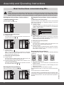
1
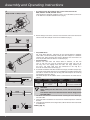
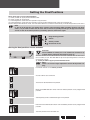
R8/17C PR+ - R40/17C PR+ en Assembly and Operating Instructions Tubular drives for roller shutters Wi th plu Ne w co g g : nn a b ec tin le B g c eck ab er le Important information for: • Fitters • Electricians • Users Please forward accordingly! These instructions must be kept for future reference. Becker-Antriebe GmbH 35764 Sinn/Germany www.becker-antriebe.com Assembly and Operating Instructions Table of Contents General....................................................................................................................................................................... 2 Warranty...................................................................................................................................................................... 3 Safety Information........................................................................................................................................................ 3 Intended use............................................................................................................................................................... 4 Mounting and installation instructions............................................................................................................................ 5 Setting the Final Positions............................................................................................................................................. 7 Information for the Electrician..................................................................................................................................... 13 Disposal.................................................................................................................................................................... 13 Declaration of Conformity........................................................................................................................................... 13 Technical Data........................................................................................................................................................... 13 Torque recognition..................................................................................................................................................... 13 What to do if...?.......................................................................................................................................................... 14 Sample wiring diagram............................................................................................................................................... 15 Brief instructions commissioning PR+.......................................................................................................................... 16 General The R8/17C PR+ - R40/17C PR+ tubular drives are high-quality products with numerous performance features: • Installation possible without buffers (lower position to upper position) • Automatic recognition of final positions due to intelligent electronic system when using buffer systems • Secure anti-lifting device • Slight pressure applied on the roller shutters prevents them from being raised or forced open • Suitable for rigid aluminium, steel and wooden profiles • The final positions do not have to be reset: Shutters are realigned automatically when using buffer systems • Emergency Stop in accordance with the European Machinery Directive (anti-restart device) • Torque control prevents damage to the roller shutter in the event of a frozen or blocked shutter • Optimum adjustment of the closing torque to the system • Smooth operation of the system and the drive increases the service life • No external limit switches • Simple final position setting of the shutter at the push of a button either via an installation set or via a drive switch • Left or right-hand installation • Several electric drives can be switched in parallel • Suitable for all Becker control units • Compatible with previous motors (4-core connection cable) • With pluggable Becker connecting cable Always observe these assembly and operating instructions when installing and setting the device. 2 Warranty Structural modifications and incorrect installation which are not in accordance with these and our other instructions can result in serious injuries, e.g. crushing of limbs. Therefore, structural modifications should only be carried out with our prior approval and in accordance with our instructions, particularly the information contained in these Assembly and Operating Instructions. Any further processing of the products which does not comply with their intended use is not permitted. The end product manufacturer and fitter have to ensure that all the current statutory, official regulations and, in particular, EMC regulations are adhered to during utilisation of our products, especially with regard to end product assembly, installation and customer advice. Safety Information The following safety instructions and warnings are intended to avert hazards and to prevent damage to property and personal injuries. Please retain for future reference. • • • • • • • • • Caution Denotes a potentially hazardous situation. If this is not avoided, injuries may result. Attention Denotes a potentially hazardous situation. If this is not avoided, the product or something in its vicinity may be damaged. Note Denotes user tips and other useful information. Important safety instructions for the user Caution! Failure to observe these instructions can lead to serious injuries. All operational work including maintenance and cleaning, on electrical installations as well as other parts of the construction must always be performed by authorised specialists, especially by qualified electricians. Do not allow children to play with control units. Systems have to be regularly checked by authorised specialists for wear and damages. Always put damaged systems out of operation immediately until they are repaired by an authorised specialist. Do not operate equipment if people or objects are within the danger zone. Observe the danger zone of the equipment during operation. Bring the equipment to a stop and disconnect the mains power supply when maintenance and cleaning jobs are performed either on the system itself or in the immediate vicinity of it. Ensure that there is an adequate distance (at least 40 cm) between moving parts and adjacent objects. Crushing and shearing points must be avoided or protected. 3 Assembly and Operating Instructions • • • • • • • • • • • • • • • • • • • • Important safety instructions for the installation and commissioning Caution! Failure to observe these instructions can lead to serious injuries. Please comply with the safety instructions EN 60335-2-97. Please note that these safety instructions cannot be assumed as being complete, since this standard does not consider all the possible causes of risk. For example, the construction of the operated product, the effectiveness of the drive in the location of installation or the mounting of the final product in the end user’s place of usage cannot be taken into consideration by the drive manufacturer. If any questions or concerns regarding the safety instructions contained in the standard arise, please contact the manufacturer of the respective part or end product. All operational work, including maintenance and cleaning, on electrical installations as well as other system parts must always be performed by authorised specialists, especially qualified electricians. During operation of electrical or electronic equipment and units, certain components are subject to a hazardous electrical voltage. Physical injuries or damage to property can result in the event of unqualified interventions or failure to comply with the warning notices. All applicable standards and regulations for the electrical installation must be complied with. Only use spare parts, tools and additional equipment which have been approved by the drive manufacturer. Unapproved third party products or modifications to the system and its accessories represent a risk to your safety and the safety of others. This means that the utilisation of unapproved third party products, or modifications which have not been agreed with or approved by us are prohibited. We shall not accept liability for damages arising from such actions. Before installation, shut down all lines and control devices that are not essential for operation. Position control devices within sight of the driven product at a height of over 1.5 m. Stationary mounted control units have to be fixed in sight. Ensure that there is an adequate distance (at least 40 cm) between moving parts and adjacent objects. Nominal torque and duty cycle must be suitable for the requirements of the driven product. Technical data nominal torque and service life are located on the type plate of the tubular drive. Moveable parts of the drive have to be mounted at a height of more than 2,5 m above ground or on a different level, which allows access to the drive. Crushing or shearing points must be avoided or protected. Observe safety distances in accordance with DIN EN 294. When installing the drive, an all-pole separation capability from the mains with at least 3 mm contact opening width per pole must be provided (EN 60335). If the mains cable is damaged, it must be replaced with an identical mains cable (pluggable) supplied by the drive manufacturer. Never handle the drive via the mains cable. Drives with a H05VV-F connection cable are only to be used inside the building. Drives from Becker Antriebe are to be mounted and operated solely with mechanical accessory components shown in the current Becker product catalogue. Intended use The R8/17C PR+ - R40/17C PR+ tubular drives are intended solely for use in roller shutters. The tubular drive supports not only shutter suspension via springs but also mechanical anti-lifting devices (e.g. Zurfluh-Feller, Simu, GAH Alberts and Deprat). These are detected automatically. The mains connection cable is not suitable for supporting the weight of the drive. Always support the drive with the housing tube. Note The tubular drives have been designed for use in single systems (one roller shutter per winding shaft and drive) If several roller shutters are operated on one winding shaft, torque control and correct functioning of the anti-lifting device are not guaranteed. Other applications, utilisation and modifications are not permitted in order to protect the safety of the users and others, since these actions can impair the system’s safety, resulting in personal injuries and property damage. Becker-Antriebe shall not accept liability for damages arising from such actions. Always observe the information in these instructions when operating or repairing the system. Becker-Antriebe shall not accept liability for damages resulting from incorrect usage. 4 Attention Anti-lifting devices may only be used if sufficiently rigid roller shutter laths are used. When closed, the shutters must not extend over the guide rails, as this may put too great a load on the joint between the top two slats, which could consequently be damaged. Before reaching the lower end limit, the roller shutters must have made at least 1.5 revolutions. This is normally the case when the window height is five times the effective tube diameter. Example: 60-series octagonal tube with anti-lifting device from Zurfluh-Feller: Effective tube diameter: 9 cm -> min. window height > 45 cm Mounting and installation instructions 1 Click Location lug Self-locking clip Assembly of the Becker connecting cable (Fig. 1) Ensure the Becker connecting cable is de-energised before proceeding. Insert the cable into the drive head until the location lug audibly engages behind the self-locking clip. If necessary, use a suitable flat-bladed screwdriver to insert the cable correctly. This is done by inserting the screwdriver into one of the two recesses in the connector. Check the locking. Disassembly of the Becker connecting cable (Fig. 1) Caution Always completely de-energise the Becker connecting cable prior to disassembly. 1. Carefully insert a suitable flat-bladed screwdriver into the recess of the self-locking clip until it releases the location lug of the connecting cable. 2. It is now possible to carefully withdraw the Becker connecting cable along with the flat-bladed screwdriver. 1. 2. 2 3 R8/17C PR+ to R20/17C PR+ Caution Electrical connections may only be carried out by a qualified electrician. Prior to assembly, the power supply should be disconnected. Please give the enclosed connection information to the electrical fitter carrying out the work. Prior to mounting, the fitter must ensure that the masonry and the shutter box are sufficiently robust (drive torque plus weight of the shutters). Attention Drives from Becker Antriebe are to be mounted and operated solely with mechanical accessory components shown in the current Becker product catalogue. 1. Establish the room required at the side for mounting (M) of the head piece, thrust bracket and motor bracket , in order to calculate the required length of roller tube. The internal dimension of the roller shutter box (X) minus the overall length of wall bracket+head piece (M) and thrust bracket (T) gives the length (L) of the roller tube: L=X-(T+M) (Fig. 2). Measure the distance from the wall bracket and connecting head since this can vary according to the combination of motor and bracket. 2. Then fix wall and thrust bracket. Please observe the following when assembling the drive: • Assembly of the drive adapter with locking device for the R8/17C PR+ to R20/17C PR+ drives: You can see how to insert the locking device from its shape. When inserting the locking device, ensure that the catch locks into place. You will hear a click. Check that the locking device is in position properly by pulling on the drive adapter (Fig. 3). 5 Assembly and Operating Instructions 4 • Assembly of the drive adapter with screw connection for the R30/17C PR+ to R40/17C PR+ drives: Here the drive is fixed with an M6x12 screw. It is secured with a plain washer for M6 and a suitable toothed washer (Fig. 4). 5 3. Before fitting in the barrel, take the measurement from barrel end to the centre of the drive adapter and mark on the barrel (Fig. 5). 6 • For profile tubes: For some drive adapters, tolerances of the channel widths in different roller tubes can be balanced by turning the drive adapter in a different channel slot. These channel slots come in different sizes and make it an exact fit possible when the drive is installed (Fig. 6). • For round tubes: Release the tube from the motor died in advance, so that the cam of the ring can also be inserted into the tube. The cam of the ring must not engage with the tube. For rings without pulling cams, the roller tube must be connected to the ring by a 4.8 x 10 mm sheet-metal screw (Fig. 7). 4. Assemble the tubular drive with the relevant ring (A) and drive adapter (B). Insert the tubular drive with the pre-assembled ring and drive adapter into the tube as shown. Ensure that the ring and drive adapter are correctly positioned in the tube. (Fig. 8) The drive adapter of the tubular drive is connected to the roller tube as follows: R30/17C PR+ to R40/17C PR+ 7 Size of drive [mm] Ø 45 8 9 6 Roller shutter tubes–Ø [mm] 60 - 70 mm plastic or diecast drive adapter Torque max. [Nm] Fastening screws for drivers (4 x) 50 flat-headed sheet-metal screw ST 6.3 x 10 DIN 7982 Attention When drilling into the roller tube, never drill near the tubular drive! The tubular drive must not be hit into the tube or dropped into the roller tube! The drive manufacturer also recommends screwing the thrust bearing to the roller tube. 5. Hang the tube in the bracket and secure the motorhead piece in the drive bracket. 6. Hang the mounted unit consisting of tube, tubular drive and thrust bracket in the bracket. Cabling (Fig. 9) Setting the Final Positions There are 4 ways to set the final positions: a) Lower position to upper position without buffer b) Lower position to upper buffer c) Anti-lifting device at the lower final position to upper buffer d) Anti-lifting device at the lower final position to upper position without buffer (only via installation set) The final limit position becomes fixed, after the tubular drive has turned off automatically, in the desired position, three times. Note If, due to an obstruction, the tubular drive switches off prematurely while travelling upwards and downwards, it is possible to relieve the obstacle and to remove it by briefly travelling in the opposite direction, and to set the desired final position by travelling upwards/downwards again. Programming position Switch Delete position Directional arrows Setting the final positions via the switches Attention The installation assembly set is not suitable for continuous operation and has only been designed for start-up. Connect the wires of the tubular drive to the same coloured wires of the installation assembly set (Art. No. 4901 002 181 0) or the operating element and switch on the mains supply. a) Lower position to upper position without buffer Note There is no shutter length adjustment for this final position setting. Push both switches to the delete position. Actuate a brief start command. Travel to the desired lower final position. Move the DOWN direction switch from the delete position to the programmed position. Subsequently travel to the desired upper final position. Now move the UP direction switch from the delete position to the programmed position. The final positions have now been set. 7 Assembly and Operating Instructions b) Lower position to upper buffer Push both buttons to the delete position. Actuate a brief start command. Travel to the desired lower final position. Move the DOWN direction switch from the delete position to the programmed position. Subsequently travel upwards against the permanent upper buffer until the tubular drive automatically switches off. The final positions have now been set. c) Anti-lifting device at the lower final position to upper buffer Move both buttons to the delete position. Actuate a brief start command. Move both buttons to the programmed position. Travel to the lower final position until the tubular drive automatically switches off. Subsequently travel upwards against the permanent upper buffer until the tubular drive automatically switches off. The final positions have now been set. 8 Deleting the Final Positions via the Switches a) Deleting the final positions individually Note It is only possible to delete an individual final position if lower position to upper position without buffer has been programmed via the switches. Move the switch of the respective final position from the programming position to the delete position. Actuate a brief start command. The final position has now been deleted. b) Deleting both final positions Move both switches from the programming position to the delete position. Actuate a brief start command. Both final positions have now been deleted. 9 Assembly and Operating Instructions Setting the Final Positions via the Installation Set Attention The installation set is not suitable for continuous operation and has only been designed for set-up. Connect the wires of the tubular drive to the same coloured wires of the installation set (Art. No. 4935 200 011 0) and switch on the mains supply. Note If, due to an obstruction, the tubular drive switches off prematurely while travelling upwards and downwards, it is possible to relieve the obstacle and to remove it by briefly travelling in the opposite direction, and to set the desired final position by travelling upwards/downwards again. Action Response a) Lower position to upper position without buffer Note There is no shutter length adjustment for this final position setting. Move both switches to the programming position. Travel to the desired lower final position. Press the programming button of the installation set for 3 seconds. The tubular drive makes a “clack” sound to confirm. clack Subsequently travel to the desired upper final position. Now press the programming button of the installation set for 3 seconds. The tubular drive makes a “clack” sound to confirm. clack The final positions have now been set. b) Lower position to upper buffer Move both switches to the programming position. Travel to the desired lower final position. Press the programming button of the installation set for 3 seconds. The tubular drive makes a “clack” sound to confirm. Subsequently travel upwards against the permanent upper buffer. The tubular drive switches off automatically. clack The final positions have now been set. 10 Action Response c) Anti-lifting device at the lower final position to upper buffer Move both switches to the programming position. Travel downwards until the lower final position. The tubular drive switches off automatically. Subsequently travel upwards against the permanent upper buffer. The tubular drive switches off automatically. The final positions have now been set. d) Anti-lifting device at the lower final position to upper position without buffer Move both switches to the programming position. Travel downwards until the lower final position. The tubular drive switches off automatically. Subsequently travel to the desired upper final position. Now press the programming button of the installation set for 3 seconds. The tubular drive makes a “clack” sound to confirm. clack The final positions have now been set. 11 Assembly and Operating Instructions Deleting the final positions via the installation set Action Response a) Deleting one final position if two final positions have been programmed Travel to the final position which is to be deleted. 1. Press the reset button (1) 2. Additionally press and hold the downward button (2). 3. Now release the reset button (1), but keep the downward button (2) pressed. clack 4. Additionally press the reset button (1) again. The tubular drive makes a “clackclack” sound to confirm. clack The final position has been deleted. b) Deleting both final positions Travel the shutter to a position between both final positions. 1. Press the reset button (1) 2. Additionally press and hold the downward button (2). 3. Now release the reset button (1), but keep the downward button (2) pressed. clack 4. Additionally press the reset button (1) again. clack Both final positions have been deleted. 12 The tubular drive makes a “clackclack” sound to confirm. Information for the Electrician Becker tubular drives with electronic limit switching can be parallel connected. The maximum switching contact loading of the control device (timer, relay control, switch, etc.) must be observed. Use external conductor L1 to control the up and down direction. Other devices or consumption units (lamps, relays, etc.) must not be directly connected to the drive connection cables. For this purpose, the drives and additional units must be decoupled by relay controls. When installing the drive, an all-pole separation capability from the mains with at least 3mm contact opening width per pole must be provided (EN 60335). Attention Only use mechanically or electrically locked switching elements with a marked zero position! This also applies when drives with electronic and mechanical limit switching are used in the same system. The changeover time for changing the running direction must be at least0,5 s. Switch and control must not execute simultaneous UP and DOWN commands. To operate drives with electronic limit switching, only use control elements (time controls) which do not draw N potential via the drive. The outputs of the control element must be potential-free in the neutral position. Protect the electrical connections from damp. Note Becker tubular drives bear the CE mark. These drives comply with the valid EU guidelines and meet EMC regulations. If the drive is to be operated with units which contain sources of interference, the electrician must ensure suitable interference suppression for the relevant devices. Disposal This product consists of various materials which must be disposed of correctly. Please find out more about relevant national legislations governing the recycling and disposal systems for this product. The packaging material must be disposed of correctly. Declaration of Conformity Becker tubular drives display the CE mark. These drives comply with valid EU directives and meet EMC requirements. The complete Declaration of Conformity can be requested from the manufacturer. Technical Data Type Nominal torque (Nm) Output speed (min-1) Limit switch range Mains voltage Power consumption (W) Nominal current consumption (A) Operating mode Protection class Min. tube diameter (mm) R8/17C PR+ 8 17 R12/17C PR+ 12 17 100 0.45 110 0.50 R20/17C PR+ 20 17 64 revolutions 230V/50Hz 160 0.75 S2 4 min. IP 44 47 R30/17C PR+ 30 17 R40/17C PR+ 37 17 205 0.90 230 1.18 Torque recognition A correctly installed tubular drive cuts off in the event of an exceptionally strong load increase in the UP/DOWN direction, thus preventing overloading of the tubular drive, for example, if the end rail or moulding freezes. 13 Assembly and Operating Instructions What to do if...? Problem Tubular drive overruns the end limit or does not reach the set end limit.. Remedy 1. Investigate source, dry out the system and reprogramme. 2. External devices are connected to the power 2. Check electrical installation, remove exleads of the tubular drive. ternal device if connected, reprogramme system. 3. L1 and N connection have been reversed. 3. Exchange L1 and N (N = blue, L1 = black/ brown), reset the end limits. 4. End stops have become detached or one or 4. Repair system; reset tubular drive, then more suspension devices have broken. reset the end limits. Tubular drive stops 1. Tubular drive is overloaded. 1. Use a more powerful tubular drive. arbitrarily, impossible 2. System keeps jamming, friction is too high. 2. Ensure that the system runs smoothly. for it to move further in 3. Assembly of a tubular drive with previously 3. Delete the end limits and reinstall them. the same direction. programmed final positions. Tubular drive does not 1. Tubular drive is overheated. 1. The tubular drive is operational again after a run in the direction few minutes. required. 2. Tubular drive is faulty (does not work even 2. Replace the tubular drive; carry out RESET after standing still for a long period of time). via the programming button. No click may be heard (emergency programme), tubular drive can be moved up and down using the setting controls for the purpose of dismounting the drive. 3. Tubular drive switched off when it encoun3. Move the curtain or canopy away from the tered an obstacle the last time it moved in obstacle, remove the obstacle and set the the same direction. drive to move in the direction required. 4. Electrical connection faulty. 4. Check the electrical connection. Tubular drive only runs Tubular drive is in error mode (obstacle recog- Reset the end limits or replace the tubular drive. for approx. 5 secs. nition malfunctioning). When you attempt to The end limits have already been set using the Move both switches to the reset position. set the end limits using switches. Press the control command briefly. the setting controls, Move both switches to the programming posithis does not work. tion simultaneously. Reset the end limits using the setting controls. When you attempt to The end limits have been reached more than 16 Move both switches to the reset position. set the end limits using times. Press the control command briefly. the switches, this does Reset the end limits. not work. During programming For safety reasons the drive reacts cautiously to Briefly travel DOWN and subsequently UP until travel the drive does unsmooth running during programming travel, you reach the upper limit stop. not reach the limit stop thus preventing damages. which is to be programmed 14 Cause 1. A short circuit caused by dampness. Sample wiring diagram Electronics Green-Yellow Blue Brown Black Electronics Controlling one/several drive(s) via a single switch/button Individual switch Subject to technical changes without notice 15 Assembly and Operating Instructions Brief instructions commissioning PR+ Caution Always adhere to the information contained in the assembly and operating instructions during commissioning, operation and repair work. The manufacturer or supplier shall not accept liability for personal injuries, property damage or consequential damages resulting from non-adherence to the instructions. Setting the final positions via the switches 1. Deleting both final positions Set both switches to . Actuate a brief start command. 1. Setting the lower final position Connect the wires of the tubular drive to the same coloured wires of the installation set. Slide both switches to the programming position (I). a: To lower position Travel the shutter to the desired position and press the programming button on the installation set until the drive makes a “clack” sound. 3. Setting the upper final position a: To upper buffer Travel the shutter upwards against the upper buffer until the tubular drive automatically switches off. b: To upper position (only possible with installation set in case of anti-lifting devices) Travel the shutter to the desired upper position and move the respective switch from to . Move the respective switch from to . b: To lower buffer When using anti-lifting devices (permanent suspension device), travel the shutter downwards direction until the tubular drive automatically switches off. 2. Setting the upper final positions a: To upper buffer Travel the shutter upwards against the upper buffer until the tubular drive automatically switches off. b: To upper position Travel the shutter to the desired upper position and press the programming button on the installation set until the drive makes a “clack” sound. Deleting the final position(s) To delete the final positions, execute the following “deleting sequence”: 2. 3. 4. 1. 1. Press the reset button (1). 2. Additionally press the travel button (2) downwards and keep it pressed. 3. Now release the reset button (1) while keeping the travel button (2) pressed. 4. Additionally press the reset button (1) again. The tubular drive makes a “clack-clack” sound to confirm deletion. The final position has now been deleted. If the tubular drive is located between the final positions, both final positions are deleted. If the tubular drive is located at one of the two final positions, only the respective final position is deleted. 16 08/09 b: To lower buffer Set both switches to . When using anti-lifting devices (permanent suspension device), travel the shutter downwards until the tubular drive automatically switches off. clack 2010 300 326 0c 2. Setting the lower final position a: To lower position Travel the shutter to the desired position and move the reto . spective switch from Deleting the final position(s) Setting the final positions via the installation set